JP2010001803A - Catalyst deterioration determination device - Google Patents
Catalyst deterioration determination device Download PDFInfo
- Publication number
- JP2010001803A JP2010001803A JP2008161491A JP2008161491A JP2010001803A JP 2010001803 A JP2010001803 A JP 2010001803A JP 2008161491 A JP2008161491 A JP 2008161491A JP 2008161491 A JP2008161491 A JP 2008161491A JP 2010001803 A JP2010001803 A JP 2010001803A
- Authority
- JP
- Japan
- Prior art keywords
- oxygen concentration
- concentration parameter
- catalyst
- upstream
- downstream
- Prior art date
- Legal status (The legal status is an assumption and is not a legal conclusion. Google has not performed a legal analysis and makes no representation as to the accuracy of the status listed.)
- Granted
Links
Images


Classifications
-
- F—MECHANICAL ENGINEERING; LIGHTING; HEATING; WEAPONS; BLASTING
- F01—MACHINES OR ENGINES IN GENERAL; ENGINE PLANTS IN GENERAL; STEAM ENGINES
- F01N—GAS-FLOW SILENCERS OR EXHAUST APPARATUS FOR MACHINES OR ENGINES IN GENERAL; GAS-FLOW SILENCERS OR EXHAUST APPARATUS FOR INTERNAL COMBUSTION ENGINES
- F01N11/00—Monitoring or diagnostic devices for exhaust-gas treatment apparatus, e.g. for catalytic activity
- F01N11/007—Monitoring or diagnostic devices for exhaust-gas treatment apparatus, e.g. for catalytic activity the diagnostic devices measuring oxygen or air concentration downstream of the exhaust apparatus
-
- F—MECHANICAL ENGINEERING; LIGHTING; HEATING; WEAPONS; BLASTING
- F02—COMBUSTION ENGINES; HOT-GAS OR COMBUSTION-PRODUCT ENGINE PLANTS
- F02D—CONTROLLING COMBUSTION ENGINES
- F02D41/00—Electrical control of supply of combustible mixture or its constituents
- F02D41/02—Circuit arrangements for generating control signals
- F02D41/021—Introducing corrections for particular conditions exterior to the engine
- F02D41/0235—Introducing corrections for particular conditions exterior to the engine in relation with the state of the exhaust gas treating apparatus
-
- F—MECHANICAL ENGINEERING; LIGHTING; HEATING; WEAPONS; BLASTING
- F02—COMBUSTION ENGINES; HOT-GAS OR COMBUSTION-PRODUCT ENGINE PLANTS
- F02D—CONTROLLING COMBUSTION ENGINES
- F02D41/00—Electrical control of supply of combustible mixture or its constituents
- F02D41/02—Circuit arrangements for generating control signals
- F02D41/14—Introducing closed-loop corrections
- F02D41/1438—Introducing closed-loop corrections using means for determining characteristics of the combustion gases; Sensors therefor
- F02D41/1439—Introducing closed-loop corrections using means for determining characteristics of the combustion gases; Sensors therefor characterised by the position of the sensor
- F02D41/1441—Plural sensors
-
- F—MECHANICAL ENGINEERING; LIGHTING; HEATING; WEAPONS; BLASTING
- F02—COMBUSTION ENGINES; HOT-GAS OR COMBUSTION-PRODUCT ENGINE PLANTS
- F02D—CONTROLLING COMBUSTION ENGINES
- F02D41/00—Electrical control of supply of combustible mixture or its constituents
- F02D41/02—Circuit arrangements for generating control signals
- F02D41/14—Introducing closed-loop corrections
- F02D41/1438—Introducing closed-loop corrections using means for determining characteristics of the combustion gases; Sensors therefor
- F02D41/1444—Introducing closed-loop corrections using means for determining characteristics of the combustion gases; Sensors therefor characterised by the characteristics of the combustion gases
- F02D41/1454—Introducing closed-loop corrections using means for determining characteristics of the combustion gases; Sensors therefor characterised by the characteristics of the combustion gases the characteristics being an oxygen content or concentration or the air-fuel ratio
-
- F—MECHANICAL ENGINEERING; LIGHTING; HEATING; WEAPONS; BLASTING
- F02—COMBUSTION ENGINES; HOT-GAS OR COMBUSTION-PRODUCT ENGINE PLANTS
- F02D—CONTROLLING COMBUSTION ENGINES
- F02D41/00—Electrical control of supply of combustible mixture or its constituents
- F02D41/02—Circuit arrangements for generating control signals
- F02D41/18—Circuit arrangements for generating control signals by measuring intake air flow
-
- G—PHYSICS
- G01—MEASURING; TESTING
- G01M—TESTING STATIC OR DYNAMIC BALANCE OF MACHINES OR STRUCTURES; TESTING OF STRUCTURES OR APPARATUS, NOT OTHERWISE PROVIDED FOR
- G01M15/00—Testing of engines
- G01M15/04—Testing internal-combustion engines
- G01M15/10—Testing internal-combustion engines by monitoring exhaust gases or combustion flame
- G01M15/102—Testing internal-combustion engines by monitoring exhaust gases or combustion flame by monitoring exhaust gases
- G01M15/104—Testing internal-combustion engines by monitoring exhaust gases or combustion flame by monitoring exhaust gases using oxygen or lambda-sensors
-
- F—MECHANICAL ENGINEERING; LIGHTING; HEATING; WEAPONS; BLASTING
- F01—MACHINES OR ENGINES IN GENERAL; ENGINE PLANTS IN GENERAL; STEAM ENGINES
- F01N—GAS-FLOW SILENCERS OR EXHAUST APPARATUS FOR MACHINES OR ENGINES IN GENERAL; GAS-FLOW SILENCERS OR EXHAUST APPARATUS FOR INTERNAL COMBUSTION ENGINES
- F01N2550/00—Monitoring or diagnosing the deterioration of exhaust systems
- F01N2550/02—Catalytic activity of catalytic converters
-
- F—MECHANICAL ENGINEERING; LIGHTING; HEATING; WEAPONS; BLASTING
- F01—MACHINES OR ENGINES IN GENERAL; ENGINE PLANTS IN GENERAL; STEAM ENGINES
- F01N—GAS-FLOW SILENCERS OR EXHAUST APPARATUS FOR MACHINES OR ENGINES IN GENERAL; GAS-FLOW SILENCERS OR EXHAUST APPARATUS FOR INTERNAL COMBUSTION ENGINES
- F01N2560/00—Exhaust systems with means for detecting or measuring exhaust gas components or characteristics
- F01N2560/02—Exhaust systems with means for detecting or measuring exhaust gas components or characteristics the means being an exhaust gas sensor
- F01N2560/025—Exhaust systems with means for detecting or measuring exhaust gas components or characteristics the means being an exhaust gas sensor for measuring or detecting O2, e.g. lambda sensors
-
- F—MECHANICAL ENGINEERING; LIGHTING; HEATING; WEAPONS; BLASTING
- F01—MACHINES OR ENGINES IN GENERAL; ENGINE PLANTS IN GENERAL; STEAM ENGINES
- F01N—GAS-FLOW SILENCERS OR EXHAUST APPARATUS FOR MACHINES OR ENGINES IN GENERAL; GAS-FLOW SILENCERS OR EXHAUST APPARATUS FOR INTERNAL COMBUSTION ENGINES
- F01N2560/00—Exhaust systems with means for detecting or measuring exhaust gas components or characteristics
- F01N2560/14—Exhaust systems with means for detecting or measuring exhaust gas components or characteristics having more than one sensor of one kind
-
- F—MECHANICAL ENGINEERING; LIGHTING; HEATING; WEAPONS; BLASTING
- F01—MACHINES OR ENGINES IN GENERAL; ENGINE PLANTS IN GENERAL; STEAM ENGINES
- F01N—GAS-FLOW SILENCERS OR EXHAUST APPARATUS FOR MACHINES OR ENGINES IN GENERAL; GAS-FLOW SILENCERS OR EXHAUST APPARATUS FOR INTERNAL COMBUSTION ENGINES
- F01N3/00—Exhaust or silencing apparatus having means for purifying, rendering innocuous, or otherwise treating exhaust
- F01N3/08—Exhaust or silencing apparatus having means for purifying, rendering innocuous, or otherwise treating exhaust for rendering innocuous
- F01N3/0807—Exhaust or silencing apparatus having means for purifying, rendering innocuous, or otherwise treating exhaust for rendering innocuous by using absorbents or adsorbents
- F01N3/0828—Exhaust or silencing apparatus having means for purifying, rendering innocuous, or otherwise treating exhaust for rendering innocuous by using absorbents or adsorbents characterised by the absorbed or adsorbed substances
- F01N3/0864—Oxygen
-
- F—MECHANICAL ENGINEERING; LIGHTING; HEATING; WEAPONS; BLASTING
- F02—COMBUSTION ENGINES; HOT-GAS OR COMBUSTION-PRODUCT ENGINE PLANTS
- F02D—CONTROLLING COMBUSTION ENGINES
- F02D2200/00—Input parameters for engine control
- F02D2200/02—Input parameters for engine control the parameters being related to the engine
- F02D2200/08—Exhaust gas treatment apparatus parameters
- F02D2200/0816—Oxygen storage capacity
-
- Y—GENERAL TAGGING OF NEW TECHNOLOGICAL DEVELOPMENTS; GENERAL TAGGING OF CROSS-SECTIONAL TECHNOLOGIES SPANNING OVER SEVERAL SECTIONS OF THE IPC; TECHNICAL SUBJECTS COVERED BY FORMER USPC CROSS-REFERENCE ART COLLECTIONS [XRACs] AND DIGESTS
- Y02—TECHNOLOGIES OR APPLICATIONS FOR MITIGATION OR ADAPTATION AGAINST CLIMATE CHANGE
- Y02T—CLIMATE CHANGE MITIGATION TECHNOLOGIES RELATED TO TRANSPORTATION
- Y02T10/00—Road transport of goods or passengers
- Y02T10/10—Internal combustion engine [ICE] based vehicles
- Y02T10/40—Engine management systems
Abstract
Description
本発明は、内燃機関から排出された排ガスを浄化する触媒の劣化判定装置に関する。 The present invention relates to a catalyst deterioration determination device that purifies exhaust gas discharged from an internal combustion engine.
従来の触媒の劣化判定装置として、例えば特許文献1に開示されたものが知られている。この劣化判定装置では、排気通路の三元触媒よりも上流側および下流側に、内燃機関で燃焼された混合気の空燃比を検出する上流側空燃比センサおよび下流側空燃比センサがそれぞれ設けられており、三元触媒の劣化判定が以下のようにして行われる。まず、混合気の空燃比を理論空燃比よりもリーン側に制御することによって、排ガス中の酸素を三元触媒に十分に吸着させる。次に、混合気の空燃比を理論空燃比よりもリッチ側に切り換えることにより、排ガス中の未燃燃料を還元剤として三元触媒に供給し、三元触媒に吸着していた酸素と反応させる。その後、下流側空燃比センサで検出された上流側空燃比が上流側空燃比センサで検出された上流側空燃比とほぼ等しくなったときに、理論空燃比とそのときの上流側空燃比との差に、リッチ側への切換時からの経過時間(以下「第1時間」という)と、検出された吸入空気量を乗算することによって、三元触媒に吸着していた第1酸素量を算出する。
As a conventional catalyst deterioration determination device, for example, one disclosed in
次に、混合気の空燃比を再びリーン側に切り換えることにより、排ガス中の酸素を三元触媒に吸着させる。その後、下流側空燃比が上流側空燃比とほぼ等しくなったときに、そのときの上流側空燃比と理論空燃比との差に、リーン側への切換時からの経過時間(以下「第2時間」という)と、吸入空気量を乗算することによって、三元触媒に吸着した第2酸素量を算出する。そして、算出した第1および第2酸素量の平均値が小さいほど、三元触媒の劣化が進行していると判定する。 Next, the oxygen in the exhaust gas is adsorbed on the three-way catalyst by switching the air-fuel ratio of the air-fuel mixture to the lean side again. Thereafter, when the downstream air-fuel ratio becomes substantially equal to the upstream air-fuel ratio, the difference between the upstream air-fuel ratio and the stoichiometric air-fuel ratio at that time is the elapsed time (hereinafter referred to as “second” The amount of second oxygen adsorbed on the three-way catalyst is calculated by multiplying the time and the intake air amount. Then, it is determined that the deterioration of the three-way catalyst is progressing as the calculated average value of the first and second oxygen amounts is smaller.
以上のように、この従来の劣化判定装置では、空燃比をリーン側とリッチ側の間で切り換えた後、下流側空燃比が上流側空燃比と等しくなるまでの第1および第2時間に応じて算出した第1および第2酸素量に基づいて、三元触媒の劣化が判定される。しかし、上流側および下流側の空燃比センサの出力特性、特にゲインが互いにずれている場合には、下流側空燃比が上流側空燃比に実際に等しくなったタイミングを正確に把握できず、上記の第1および第2時間を正確に測定できないため、劣化判定を精度良く行えない。また、2つの空燃比センサが三元触媒を間にして配置されていて、下流側空燃比センサには三元触媒で反応が行われた後の排ガスが流入するため、両空燃比センサの間で排ガスの組成や活性度合が異なる。このため、両空燃比センサ自体のの出力特性がずれていない場合でも、それらの出力値が同じ空燃比に対して互いにずれることがあり、その場合にも、下流側空燃比が上流側空燃比に等しくなったタイミングを正確に把握できず、劣化の判定精度が低下してしまう。 As described above, in this conventional deterioration determination device, after the air-fuel ratio is switched between the lean side and the rich side, the first and second times until the downstream air-fuel ratio becomes equal to the upstream air-fuel ratio are changed. The deterioration of the three-way catalyst is determined based on the calculated first and second oxygen amounts. However, when the output characteristics of the upstream and downstream air-fuel ratio sensors, particularly when the gains are deviated from each other, the timing at which the downstream air-fuel ratio is actually equal to the upstream air-fuel ratio cannot be accurately grasped. Since the first and second times cannot be accurately measured, the deterioration determination cannot be performed with high accuracy. In addition, since the two air-fuel ratio sensors are arranged with the three-way catalyst in between, and the exhaust gas after the reaction with the three-way catalyst flows into the downstream air-fuel ratio sensor, The composition and activity of exhaust gas are different. For this reason, even if the output characteristics of the two air-fuel ratio sensors themselves are not deviated, their output values may deviate from each other with respect to the same air-fuel ratio. This makes it impossible to accurately grasp the timing when it becomes equal to, and the determination accuracy of deterioration deteriorates.
本発明は、このような課題を解決するためになされたものであり、センサ自体の出力特性のずれや排ガスの組成および活性度合の相違などによる、触媒の上流側および下流側の酸素濃度パラメータセンサの間の出力特性のずれを補償しながら、触媒の劣化判定を適切に行うことができる触媒の劣化判定装置を提供することを目的とする。 The present invention has been made to solve such a problem, and oxygen concentration parameter sensors on the upstream side and downstream side of the catalyst due to a difference in output characteristics of the sensor itself, a difference in composition and activity of exhaust gas, and the like. It is an object of the present invention to provide a catalyst deterioration determination device that can appropriately determine deterioration of a catalyst while compensating for a deviation in output characteristics between the two.
上記の目的を達成するため、本願の請求項1に係る発明は、内燃機関3の排気通路(実施形態における(以下、本項において同じ)排気管5)に設けられ、排ガスを浄化するとともに酸素を貯蔵する酸素貯蔵能力を有する触媒7の劣化判定装置であって、触媒7の上流側における排ガス中の酸素濃度を表す上流側酸素濃度パラメータ(第1当量比KACT1)を検出する第1酸素濃度パラメータセンサ(第1LAFセンサ12)と、触媒7の下流側における排ガス中の酸素濃度を表す下流側酸素濃度パラメータ(第2当量比KACT2)を検出する第2酸素濃度パラメータセンサ(第2LAFセンサ13)と、触媒7に流入する排ガスを酸化雰囲気と還元雰囲気の間で切り換えて制御する制御手段(ECU2)と、制御手段により排ガスが切り換えられた後に検出された上流側酸素濃度パラメータおよび下流側酸素濃度パラメータを、排ガスの切換時から所定期間が経過した以降に検出された上流側酸素濃度パラメータおよび下流側酸素濃度パラメータが互いに合致するように補正する補正手段(ECU2、ステップ41、ステップ51、ステップ61)と、補正された上流側酸素濃度パラメータおよび下流側酸素濃度パラメータの相互の比較結果に基づいて、触媒7の劣化を判定する劣化判定手段(ECU2、ステップ42、ステップ52、ステップ62)と、を備えることを特徴とする。
In order to achieve the above object, the invention according to
この構成によれば、内燃機関の排気通路に排ガスを浄化するための触媒が設けられている。この触媒は、酸素貯蔵能力を有しており、排ガスが酸化雰囲気のときに排ガス中の酸素を貯蔵するとともに、還元雰囲気のときに、貯蔵した酸素を排ガス中に放出する。本発明の劣化判定装置によれば、触媒の上流側における排ガス中の酸素濃度を表す上流側酸素濃度パラメータを、第1酸素濃度パラメータセンサによって検出するとともに、触媒の下流側における排ガス中の酸素濃度を表す下流側酸素濃度パラメータを、第2酸素濃度パラメータセンサによって検出する。劣化判定を行う際には、触媒に流入する排ガスを酸化雰囲気および還元雰囲気の一方から他方に切り換えるとともに、その切換後に検出された上流側酸素濃度パラメータおよび下流側酸素濃度パラメータの相互の比較結果に基づいて、触媒の劣化を判定する。 According to this configuration, the catalyst for purifying the exhaust gas is provided in the exhaust passage of the internal combustion engine. This catalyst has an oxygen storage capacity, stores oxygen in the exhaust gas when the exhaust gas is in an oxidizing atmosphere, and releases the stored oxygen into the exhaust gas when in a reducing atmosphere. According to the deterioration determination device of the present invention, the upstream oxygen concentration parameter indicating the oxygen concentration in the exhaust gas upstream of the catalyst is detected by the first oxygen concentration parameter sensor, and the oxygen concentration in the exhaust gas downstream of the catalyst is detected. Is detected by the second oxygen concentration parameter sensor. When performing the deterioration determination, the exhaust gas flowing into the catalyst is switched from one of the oxidizing atmosphere and the reducing atmosphere to the other, and the comparison result of the upstream oxygen concentration parameter and the downstream oxygen concentration parameter detected after the switching is used. Based on this, deterioration of the catalyst is determined.
触媒に流入する排ガスを酸化雰囲気と還元雰囲気の間で切り換えると、酸化雰囲気への切換の場合には、排ガス中の酸素が触媒に貯蔵され、そのときの酸素貯蔵量は、触媒の劣化度合に応じて変化する。一方、還元雰囲気への切換の場合には、排ガス中の還元剤との反応によって、触媒に貯蔵されていた酸素が排ガス中に放出され、そのときの酸素放出量は、触媒の劣化度合に応じて変化する。このため、排ガスの切換後における触媒の下流側の酸素濃度の変化状況は、触媒の劣化度合を反映し、その劣化度合が高いほど、上流側の酸素濃度に対する下流側の酸素濃度の遅れは小さくなる。したがって、排ガスの切換後に検出された上流側酸素濃度パラメータおよび下流側酸素濃度パラメータを相互に比較した結果に基づいて、触媒の劣化を適切に判定できる。 When the exhaust gas flowing into the catalyst is switched between an oxidizing atmosphere and a reducing atmosphere, when switching to an oxidizing atmosphere, oxygen in the exhaust gas is stored in the catalyst, and the oxygen storage amount at that time depends on the degree of deterioration of the catalyst. Will change accordingly. On the other hand, in the case of switching to a reducing atmosphere, oxygen stored in the catalyst is released into the exhaust gas by reaction with the reducing agent in the exhaust gas, and the oxygen release amount at that time depends on the degree of deterioration of the catalyst. Change. For this reason, the change state of the oxygen concentration on the downstream side of the catalyst after switching of the exhaust gas reflects the degree of deterioration of the catalyst, and the higher the degree of deterioration, the smaller the delay in the oxygen concentration on the downstream side with respect to the oxygen concentration on the upstream side. Become. Therefore, the deterioration of the catalyst can be appropriately determined based on the result of comparing the upstream oxygen concentration parameter and the downstream oxygen concentration parameter detected after the exhaust gas switching.
また、酸化雰囲気への切換の場合には触媒における酸素の貯蔵が終了したときに、還元雰囲気への切換の場合には触媒からの貯蔵した酸素の放出が終了したときに、触媒の下流側の排ガス中の酸素濃度は、上流側の排ガス中の酸素濃度に一致するようになる。このため、排ガスの切換時から所定期間が経過した以降においては、検出された上流側酸素濃度パラメータと下流側酸素濃度パラメータは、本来、互いに一致するはずである。そうでない場合には、第1および第2酸素濃度パラメータセンサの出力特性(ゲイン)が、センサ自体の出力特性のずれや排ガスの組成および活性度合の相違などに起因して、互いにずれていることを意味し、このときの両酸素濃度パラメータの値は、両センサ間のゲインの大きさに対応する。 In the case of switching to an oxidizing atmosphere, when the storage of oxygen in the catalyst is finished, in the case of switching to a reducing atmosphere, when the release of the stored oxygen from the catalyst is finished, the downstream side of the catalyst The oxygen concentration in the exhaust gas matches the oxygen concentration in the exhaust gas on the upstream side. For this reason, the detected upstream oxygen concentration parameter and the downstream oxygen concentration parameter should essentially match each other after a predetermined period has elapsed since the switching of the exhaust gas. Otherwise, the output characteristics (gains) of the first and second oxygen concentration parameter sensors are shifted from each other due to a shift in the output characteristics of the sensor itself, a difference in the composition and activity of the exhaust gas, etc. The values of both oxygen concentration parameters at this time correspond to the magnitude of the gain between both sensors.
本発明によれば、排ガスの切換後に検出された上流側および下流側酸素濃度パラメータを、その切換時から所定期間が経過した以降に検出された上流側酸素濃度パラメータおよび下流側酸素濃度パラメータが互いに合致するように補正する。この補正により、第1および第2酸素濃度パラメータセンサの間で出力特性のずれが生じている場合、そのずれを適切に補償できる。そして、そのように補正された上流側酸素濃度パラメータおよび下流側酸素濃度パラメータを相互に比較した結果に基づいて、触媒の劣化を判定するので、第1および第2酸素濃度パラメータセンサの出力特性のずれによる影響を受けることなく、劣化の判定を適切に行うことができ、判定精度を向上させることができる。 According to the present invention, the upstream oxygen concentration parameter and the downstream oxygen concentration parameter detected after the switching of the exhaust gas are the same as the upstream oxygen concentration parameter and the downstream oxygen concentration parameter detected after a predetermined period has elapsed since the switching. Correct to match. With this correction, if there is a deviation in output characteristics between the first and second oxygen concentration parameter sensors, the deviation can be compensated appropriately. Since the deterioration of the catalyst is determined based on the result of comparison between the upstream oxygen concentration parameter and the downstream oxygen concentration parameter corrected as described above, the output characteristics of the first and second oxygen concentration parameter sensors are determined. Without being affected by the deviation, it is possible to appropriately determine the deterioration and improve the determination accuracy.
請求項2に係る発明は、請求項1に記載の触媒7の劣化判定装置において、所定期間内に検出された上流側酸素濃度パラメータおよび下流側酸素濃度パラメータのそれぞれの積算値(第1還元剤量積算値sumkact1、第2還元剤量積算値sumkact2)を算出する積算値算出手段(ECU2、ステップ3、ステップ4)をさらに備え、補正手段は、算出された上流側酸素濃度パラメータの積算値と所定期間以降に検出された上流側酸素濃度パラメータ(第1当量比平均値avekact1)との比、および算出された下流側酸素濃度パラメータの積算値と所定期間以降に検出された下流側酸素濃度パラメータ(第2当量比平均値avekact2)との比を算出することによって、上流側酸素濃度パラメータの積算値および下流側酸素濃度パラメータの積算値をそれぞれ補正し(ステップ41)、劣化判定手段は、補正された上流側酸素濃度パラメータの積算値および下流側酸素濃度パラメータの積算値の相互の比較結果に基づいて、触媒7の劣化を判定する(ステップ42)ことを特徴とする。
According to a second aspect of the present invention, in the deterioration determination device for the
この構成によれば、排ガスの切換後の所定期間内に検出された上流側酸素濃度パラメータおよび下流側酸素濃度について、それぞれの積算値を算出するとともに、各積算値と所定期間以降に検出された、対応する酸素濃度パラメータとの比を算出することによって、各積算値を補正する。そして、補正された両積算値の比較結果に基づいて、触媒の劣化を判定する。 According to this configuration, the integrated values are calculated for the upstream oxygen concentration parameter and the downstream oxygen concentration detected within a predetermined period after the exhaust gas is switched, and each integrated value is detected after the predetermined period. Each integrated value is corrected by calculating a ratio with the corresponding oxygen concentration parameter. Then, the deterioration of the catalyst is determined based on the corrected comparison result of the two integrated values.
以上のように、劣化判定のために比較される上流側酸素濃度パラメータおよび下流側酸素濃度パラメータとして、それらの積算値を用いるので、第1および第2酸素濃度パラメータセンサの出力値の一時的な変動や誤差による影響を、適切に吸収できる。また、それぞれの積算値と、所定期間以降に検出された、対応する酸素濃度パラメータとの比を算出することによって、各積算値を補正するので、所定期間以降に検出された上流側および下流側酸素濃度パラメータが互いに合致するよう、第1および第2酸素濃度パラメータセンサのゲインのずれを適切に補償することができる。 As described above, since the integrated values are used as the upstream oxygen concentration parameter and the downstream oxygen concentration parameter to be compared for the deterioration determination, temporary output values of the first and second oxygen concentration parameter sensors are used. The effects of fluctuations and errors can be absorbed appropriately. In addition, since each integrated value is corrected by calculating the ratio between each integrated value and the corresponding oxygen concentration parameter detected after the predetermined period, the upstream side and the downstream side detected after the predetermined period It is possible to appropriately compensate for the gain shift of the first and second oxygen concentration parameter sensors so that the oxygen concentration parameters match each other.
例えば、酸素濃度パラメータセンサのゲインが大きい側にずれている場合には、所定期間内から所定期間以降の全体にわたり、大きめの酸素濃度パラメータが得られるので、所定期間内に検出された酸素濃度パラメータに基づく積算値を所定期間以降に検出された酸素濃度パラメータで除することによって、積算値を小さい側に適切かつ容易に補正できる。逆に、酸素濃度パラメータセンサのゲインが小さい側にずれている場合には、積算値を大きい側に補正できる。したがって、そのようにゲイン補正された積算値同士を比較することによって、劣化の判定をより適切に行うことができ、判定精度をさらに向上させることができる。 For example, when the gain of the oxygen concentration parameter sensor is shifted to the larger side, a larger oxygen concentration parameter is obtained from the predetermined period to the entire subsequent period, so that the oxygen concentration parameter detected within the predetermined period is obtained. By dividing the integrated value based on the value by the oxygen concentration parameter detected after a predetermined period, the integrated value can be corrected appropriately and easily to the smaller side. On the contrary, when the gain of the oxygen concentration parameter sensor is shifted to the smaller side, the integrated value can be corrected to the larger side. Therefore, by comparing the gain-corrected integrated values, deterioration can be determined more appropriately, and determination accuracy can be further improved.
請求項3に係る発明は、請求項2に記載の触媒の劣化判定装置において、補正手段は、補正された上流側酸素濃度パラメータおよび下流側酸素濃度パラメータの各積算値に、上流側酸素濃度パラメータおよび下流側酸素濃度パラメータのうち、所定期間以降に検出された一方の酸素濃度パラメータをそれぞれ乗算することにより、一方の酸素濃度パラメータを基準として、上流側酸素濃度パラメータの積算値および下流側酸素濃度パラメータの積算値をさらに補正する(ステップ51、ステップ61)ことを特徴とする。
According to a third aspect of the present invention, in the catalyst deterioration determination apparatus according to the second aspect, the correction means includes an upstream oxygen concentration parameter in each integrated value of the corrected upstream oxygen concentration parameter and downstream oxygen concentration parameter. And the downstream oxygen concentration parameter by multiplying one oxygen concentration parameter detected after the predetermined period, respectively, and using the one oxygen concentration parameter as a reference, the integrated value of the upstream oxygen concentration parameter and the downstream oxygen concentration The integrated value of the parameter is further corrected (
この構成によれば、上述したように補正された上流側および下流側酸素濃度パラメータの各積算値に、所定期間以降に検出された一方の酸素濃度パラメータをそれぞれ乗算することによって、上記一方の酸素濃度パラメータを検出する酸素濃度パラメータセンサの出力値を基準として、各積算値がゲイン補正される。例えば、上流側の第1酸素濃度パラメータセンサの出力値を基準とした場合には、触媒での反応による排ガスの組成や活性度合の変化などによる影響を受けていない排ガスを対象とした第1酸素濃度パラメータセンサの検出結果に基づき、酸素濃度をより正確に反映した上流側および下流側酸素濃度パラメータの積算値を求めることができる。 According to this configuration, by multiplying each integrated value of the upstream and downstream oxygen concentration parameters corrected as described above by one oxygen concentration parameter detected after a predetermined time period, Each integrated value is gain-corrected based on the output value of the oxygen concentration parameter sensor that detects the concentration parameter. For example, when the output value of the upstream first oxygen concentration parameter sensor is used as a reference, the first oxygen for exhaust gas that is not affected by changes in the composition or activity of the exhaust gas due to the reaction at the catalyst. Based on the detection result of the concentration parameter sensor, the integrated values of the upstream and downstream oxygen concentration parameters that more accurately reflect the oxygen concentration can be obtained.
一方、内燃機関の冷間始動後などの場合には、内燃機関から排出された排ガスの活性度合が低いため、上流側のセンサの出力が鈍くなる傾向がある。したがって、そのような場合には、下流側の第2酸素濃度パラメータセンサの出力値を基準とすることによって、触媒での反応により活性度合が高められた排ガスを対象とした第2酸素濃度パラメータセンサの検出結果に基づき、酸素濃度をより正確に反映した上流側および下流側酸素濃度パラメータの積算値を求めることができる。したがって、そのように補正された積算値同士を比較することによって、判定精度をさらに向上させることができる。 On the other hand, after the cold start of the internal combustion engine, etc., the activity of the exhaust gas discharged from the internal combustion engine is low, so the output of the upstream sensor tends to be dull. Therefore, in such a case, the second oxygen concentration parameter sensor for exhaust gas whose degree of activity is increased by the reaction at the catalyst by using the output value of the second oxygen concentration parameter sensor on the downstream side as a reference. Based on this detection result, the integrated values of the upstream and downstream oxygen concentration parameters that more accurately reflect the oxygen concentration can be obtained. Therefore, the determination accuracy can be further improved by comparing the corrected integrated values.
請求項4に係る発明は、請求項1ないし3のいずれかに記載の触媒の劣化判定装置において、上流側酸素濃度パラメータおよび下流側酸素濃度パラメータが定常状態に達したか否かを判定する定常状態判定手段(ECU2、ステップ5、ステップ7)をさらに備え、所定期間は、排ガスの切換後、上流側酸素濃度パラメータおよび下流側酸素濃度パラメータの両方が定常状態に達したと判定されるまでの期間であることを特徴とする。
According to a fourth aspect of the present invention, in the catalyst deterioration determination apparatus according to any one of the first to third aspects, a steady state in which it is determined whether or not the upstream oxygen concentration parameter and the downstream oxygen concentration parameter have reached a steady state. State determination means (ECU2,
この構成によれば、所定期間は、排ガスの切換後、上流側酸素濃度パラメータおよび下流側酸素濃度パラメータの両方が定常状態に達したと判定されるまでの期間として定められる。これにより、定常状態に達した後に検出された、互いに同じ値を示すべき上流側酸素濃度パラメータおよび下流側酸素濃度パラメータを用いて、積算値などを適切に補正でき、判定精度を確実に向上させることができる。 According to this configuration, the predetermined period is determined as a period until it is determined that both the upstream oxygen concentration parameter and the downstream oxygen concentration parameter have reached a steady state after the exhaust gas is switched. As a result, the integrated value and the like can be appropriately corrected using the upstream oxygen concentration parameter and the downstream oxygen concentration parameter that should be the same value detected after reaching the steady state, and the determination accuracy is reliably improved. be able to.
また、上記の目的を達成するため、本願の請求項5に係る発明は、内燃機関3の排気通路(排気管5)に設けられ、排ガスを浄化し、酸素を貯蔵する酸素貯蔵能力を有する上流側触媒(触媒7)の劣化を判定するとともに、排気通路の上流側触媒よりも下流側に設けられ、排ガスを浄化し、酸素を貯蔵する酸素貯蔵能力を有する下流側触媒8の劣化を判定する触媒の劣化判定装置であって、上流側触媒の上流側における排ガス中の酸素濃度を表す上流側酸素濃度パラメータ(第1当量比KACT1)を検出する第1酸素濃度パラメータセンサ(第1LAFセンサ12)と、上流側触媒と下流側触媒8との中間における排ガス中の酸素濃度を表す中間酸素濃度パラメータ(第2当量比KACT2)を検出する第2酸素濃度パラメータセンサ(第2LAFセンサ13)と、下流側触媒8の下流側における排ガス中の酸素濃度を表す下流側酸素濃度パラメータ(第3当量比KACT3)を検出する第3酸素濃度パラメータセンサ(第3LAFセンサ14)と、上流側触媒に流入する排ガスを酸化雰囲気と還元雰囲気の間で切り換えて制御する制御手段(ECU2)と、制御手段により排ガスが切り換えられた後に検出された上流側酸素濃度パラメータ、中間酸素濃度パラメータおよび下流側酸素濃度パラメータを、排ガスの切換時から所定期間が経過した以降に検出された上流側酸素濃度パラメータ、中間酸素濃度パラメータおよび下流側酸素濃度パラメータが互いに合致するように補正する補正手段(ECU2、ステップ81、ステップ91)と、補正された上流側酸素濃度パラメータ、中間酸素濃度パラメータおよび下流側酸素濃度パラメータの相互の比較結果に基づいて、上流側触媒および下流側触媒8の劣化を判定する劣化判定手段(ECU2、ステップ42、ステップ92)と、を備えることを特徴とする。
In order to achieve the above object, the invention according to
この請求項5から後述する請求項8に係る発明は、前述した請求項1〜4の発明を、触媒が上流側および下流側の2つの触媒を有する場合に適用したものである。すなわち、この構成によれば、内燃機関の排気通路には、排ガスを浄化するための上流側触媒および下流側触媒が設けられており、これらの触媒はいずれも酸素貯蔵能力を有している。本発明の劣化判定装置によれば、上流側触媒の上流側、上流側触媒と下流側触媒との中間、および下流側触媒の下流側における排ガス中の酸素濃度を表す上流側酸素濃度パラメータ、中間酸素濃度パラメータおよび下流側酸素濃度パラメータが、第1〜第3酸素濃度パラメータセンサによってそれぞれ検出される。劣化判定を行う際には、上流側触媒に流入する排ガスを酸化雰囲気および還元雰囲気の一方から他方に切り換えるとともに、その切換後に検出された上流側、中間および下流側酸素濃度パラメータを、当該切換時から所定期間が経過した以降に検出された上流側、中間および下流側酸素濃度パラメータが互いに合致するように補正する。
The invention according to
この補正により、第1〜第3酸素濃度パラメータセンサの間で出力特性(ゲイン)のずれが生じている場合、そのずれを適切に補償することができる。そして、そのように補正された上流側、中間および下流側酸素濃度パラメータを相互に比較した結果に基づいて、上流側触媒および下流側触媒の劣化を判定するので、第1〜第3酸素濃度パラメータセンサの出力特性のずれによる影響を受けることなく、両触媒の劣化の判定を適切に行うことができ、判定精度を向上させることができる。 With this correction, when a deviation in output characteristics (gain) occurs between the first to third oxygen concentration parameter sensors, the deviation can be appropriately compensated. Since the deterioration of the upstream catalyst and the downstream catalyst is determined based on the result of comparing the upstream, intermediate and downstream oxygen concentration parameters corrected as described above, the first to third oxygen concentration parameters are determined. Without being affected by the deviation of the output characteristics of the sensor, it is possible to appropriately determine the deterioration of both catalysts and improve the determination accuracy.
請求項6に係る発明は、請求項5に記載の触媒の劣化判定装置において、所定期間内に検出された上流側酸素濃度パラメータ、中間酸素濃度パラメータおよび下流側酸素濃度パラメータのそれぞれの積算値(第1還元剤量積算値sumkact1、第2還元剤量積算値sumkact2、第3還元剤量積算値sumkact3)を算出する積算値算出手段(ECU2、ステップ3、ステップ4、ステップ71)をさらに備え、補正手段は、算出された上流側酸素濃度パラメータの積算値と所定期間以降に検出された上流側酸素濃度パラメータ(第1当量比平均値avekact1)との比、算出された中間素濃度パラメータの積算値と所定期間以降に検出された上流側酸素濃度パラメータ(第2当量比平均値avekact2)との比、および算出された下流側酸素濃度パラメータの積算値と所定期間以降に検出された下流側酸素濃度パラメータ(第3当量比平均値avekact3)との比を算出することによって、上流側酸素濃度パラメータの積算値、中間酸素濃度パラメータの積算値、および下流側酸素濃度パラメータの積算値をそれぞれ補正し(ステップ41、ステップ91)、劣化判定手段は、補正された上流側酸素濃度パラメータの積算値、中間酸素濃度パラメータの積算値、および下流側酸素濃度パラメータの積算値の相互の比較結果に基づいて、上流側触媒および下流側触媒の劣化を判定する(ステップ42、ステップ92)ことを特徴とする。
According to a sixth aspect of the present invention, in the catalyst deterioration determination device according to the fifth aspect, the respective integrated values of the upstream oxygen concentration parameter, the intermediate oxygen concentration parameter, and the downstream oxygen concentration parameter detected within a predetermined period ( The system further comprises integrated value calculating means (ECU2,
この構成によれば、請求項2の発明と同様、劣化判定のために比較される上流側、中間および下流側酸素濃度パラメータとして、それらの積算値を用いるので、第1〜第3酸素濃度パラメータセンサの出力値の一時的な変動や誤差による影響を、適切に吸収できる。また、それぞれの積算値と、所定期間以降に検出された、対応する酸素濃度パラメータとの比を算出することによって、各積算値を補正するので、所定期間以降に検出された上流側、中間および下流側酸素濃度パラメータが互いに合致するよう、第1〜第3酸素濃度パラメータセンサのゲインのずれを適切に補償することができる。したがって、そのようにゲイン補正された積算値同士を比較することによって、劣化の判定をより適切に行うことができ、判定精度をさらに向上させることができる。
According to this configuration, since the integrated values are used as the upstream, intermediate and downstream oxygen concentration parameters to be compared for the deterioration determination as in the invention of
請求項7に係る発明は、請求項6に記載の触媒の劣化判定装置において、補正手段は、補正された上流側酸素濃度パラメータ、中間酸素濃度パラメータおよび下流側酸素濃度パラメータの各積算値に、上流側酸素濃度パラメータ、中間酸素濃度パラメータおよび下流側酸素濃度パラメータのうちの、所定期間以降に検出された1つの酸素濃度パラメータをそれぞれ乗算することにより、当該1つの酸素濃度パラメータを基準として、上流側酸素濃度パラメータの積算値、中間酸素濃度パラメータの積算値および下流側酸素濃度パラメータの積算値をさらに補正することを特徴とする。 According to a seventh aspect of the present invention, in the catalyst deterioration determination apparatus according to the sixth aspect, the correcting means includes the corrected upstream oxygen concentration parameter, intermediate oxygen concentration parameter, and downstream oxygen concentration parameter integrated values, By multiplying each of the upstream oxygen concentration parameter, intermediate oxygen concentration parameter, and downstream oxygen concentration parameter by one oxygen concentration parameter detected after a predetermined period, the upstream oxygen concentration parameter is used as a reference. The integrated value of the side oxygen concentration parameter, the integrated value of the intermediate oxygen concentration parameter, and the integrated value of the downstream oxygen concentration parameter are further corrected.
この構成によれば、請求項3の発明と同様、上述したように補正された上流側、中間および下流側酸素濃度パラメータの各積算値に、所定期間以降に検出された1つの酸素濃度パラメータをそれぞれ乗算することにより、1つの酸素濃度パラメータを検出する酸素濃度パラメータセンサの出力値を基準として、各積算値がゲイン補正される。したがって、補正された積算値同士を比較することによって、判定精度をさらに向上させることができる。
According to this configuration, similarly to the invention of
請求項8に係る発明は、請求項5ないし7のいずれかに記載の触媒の劣化判定装置において、上流側酸素濃度パラメータ、中間酸素濃度パラメータおよび下流側酸素濃度パラメータが定常状態に達したか否かを判定する定常状態判定手段(ECU2、ステップ5、ステップ7、ステップ72)をさらに備え、所定期間は、排ガスの切換後、上流側酸素濃度パラメータ、中間酸素濃度パラメータおよび下流側酸素濃度パラメータのいずれもが定常状態に達したと判定されるまでの期間であることを特徴とする。
The invention according to
この構成によれば、請求項4の発明と同様、所定期間は、排ガスの切換後、上流側、中間および下流側酸素濃度パラメータの両方が定常状態に達したと判定されるまでの期間として定められる。これにより、定常状態に達した後に検出された、互いに同じ値を示すべき上流側、中間および下流側酸素濃度パラメータを用いて、積算値などを適切に補正でき、したがって、判定精度を確実に向上させることができる。 According to this configuration, as in the fourth aspect of the invention, the predetermined period is determined as a period until it is determined that all of the upstream, intermediate and downstream oxygen concentration parameters have reached the steady state after the exhaust gas is switched. It is done. This makes it possible to appropriately correct the integrated value, etc., using the upstream, intermediate and downstream oxygen concentration parameters that should be detected after reaching the steady state and should show the same value, thus reliably improving the determination accuracy. Can be made.
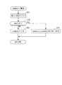
以下、図面を参照しながら、本発明の好ましい実施形態について説明する。図1は、第1実施形態による触媒の劣化判定装置1、およびこれを適用した内燃機関3を示している。この内燃機関(以下「エンジン」という)3は、車両(図示せず)に搭載されたディーゼルエンジンである。
Hereinafter, preferred embodiments of the present invention will be described with reference to the drawings. FIG. 1 shows a catalyst
エンジン3のシリンダヘッド3aには、吸気管4および排気管5が接続されるとともに、燃料噴射弁(以下「インジェクタ」という)6が、燃焼室3bに臨むように取り付けられている。このインジェクタ6は、燃焼室3bの天壁の中央に配置されており、燃料タンク(図示せず)の燃料を燃焼室3bに噴射する。インジェクタ6からの燃料噴射量は、後述するECU2によって設定され、ECU2からの駆動信号により、インジェクタ6の開弁時間が制御されることによって、制御される。
An
エンジン3には、クランク角センサ10が設けられている。クランク角センサ10は、クランクシャフト3cの回転に伴い、パルス信号であるCRK信号をECU2に出力する。CRK信号は、所定のクランク角(例えば30゜)ごとに出力される。ECU2は、このCRK信号に基づき、エンジン3の回転数(以下「エンジン回転数」という)NEを算出する。
The
吸気管4には、エアフローセンサ11が設けられている。このエアフローセンサ11は、エンジン3に吸入される吸入空気量GAIRを検出し、その検出信号をECU2に出力する。
An
排気管5には、触媒7が設けられている。この触媒7は、三元触媒で構成されており、排ガス中のHC、COおよびNOxを、酸化還元反応によって浄化する。また、触媒7は、酸素貯蔵能力を有しており、排ガスが酸素濃度の高い酸化雰囲気のときに、排ガス中の酸素を貯蔵する一方、排ガスが酸素濃度の低い還元雰囲気のときに、貯蔵していた酸素を放出する。
A
また、排気管5には、触媒7の上流側および下流側に、第1LAFセンサ12および第2LAFセンサ13がそれぞれ設けられている。これらのLAFセンサ12、13は、ジルコニアなどで構成されており、理論空燃比よりもリッチ領域から極リーン領域までの広範囲な空燃比の領域において、排ガス中の酸素濃度をリニアに検出する。第1LAFセンサ12は、触媒7の上流側における排ガス中の酸素濃度(以下「上流側酸素濃度」という)を検出し、第2LAFセンサ13は、触媒7の下流側における排ガス中の酸素濃度(以下「下流側酸素濃度」という)を検出し、それらの検出信号はECU2に出力される。
The
ECU2は、第1LAFセンサ12の検出信号に基づいて、触媒7の上流側における排ガス中の還元剤(未燃燃料)と酸素との質量比(燃空比)を換算した第1当量比KACT1を算出する。この場合、第1当量比KACT1は、混合気の燃空比と理論燃空比との比として算出される。これにより、第1当量比KACT1は、上流側酸素濃度が理論燃空比に相当するときに値1.0になり、理論燃空比に相当する値よりも低い還元雰囲気のときに1.0よりも大きな値になり、理論燃空比に相当する値よりも高い酸化雰囲気のときに、1.0よりも小さな値になる。
Based on the detection signal of the
同様に、ECU2は、第2LAFセンサ13の検出信号に基づいて、触媒7の下流側における排ガス中の還元剤と酸素との質量比を換算した第2当量比KACT2を算出する。
Similarly, based on the detection signal of the
また、ECU2は、CPU、RAM、ROMおよびI/Oインターフェースなどから成るマイクロコンピュータ(いずれも図示せず)で構成されており、前述した各種のセンサ10〜13からの検出信号などに応じて、エンジン3の運転状態を判別し、判別した運転状態に応じて、燃料噴射量制御などの各種の制御処理を実行するとともに、触媒7の劣化判定処理を実行する。なお、本実施形態では、ECU2が、制御手段、補正手段、劣化判定手段、積算値算出手段および定常状態判定手段に相当する。
The
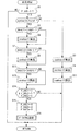
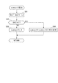
図2は、この触媒7の劣化判定処理を示すフローチャートである。本処理は、所定時間(例えば10msec)ごとに実行される。また、この劣化判定処理を実行するに際し、次のような混合気の空燃比制御が行われる。すなわち、このエンジン3はディーゼルエンジンであるため、通常、ECU2による燃料噴射量制御により、空燃比が理論空燃比よりもリーン側のリーン運転が行われており、それにより、第1当量比KACT1が値1.0よりも小さな酸化雰囲気に制御されている。劣化判定処理を行う場合には、その状態から空燃比を理論空燃比よりもリッチ側に制御することで、排ガスを、第1当量比KACT1が値1.0よりも大きな還元雰囲気に制御する。以下、このように排ガスを酸化雰囲気から還元雰囲気に切り換え、維持する制御を「排ガス還元制御」という。なお、劣化判定処理は、エンジン3が安定した所定の運転状態にあり、かつECU2および各種のセンサ10〜13が正常であることを条件として実行される。
FIG. 2 is a flowchart showing the deterioration determination process of the
まず、図2のステップ1(「S1」と図示。以下同じ)において、判定条件成立フラグF_JUDが「1」であるか否かを判別する。この判定条件成立フラグF_JUDは、排ガス還元制御中、触媒7の劣化判定条件が成立しているときに「1」にセットされるものである。この判別結果がNOのときには、そのまま本処理を終了する。
First, in
一方、ステップ1の判別結果がYESで、触媒7の劣化判定条件が成立しているときには、後述する第2還元剤量積算値sumkact2が所定値krefよりも大きいか否かを判別する(ステップ2)。この判別結果がNOのときには、第1還元剤量積算値sumkact1および第2還元剤量積算値sumkact2を算出し(ステップ3および4)、本処理を終了する。ここで、第1還元剤量積算値sumkact1は、排ガス還元制御中に触媒7に流入した還元剤の総量を表し、第2還元剤量積算値sumkact2は、排ガス還元制御中に触媒7を通過した還元剤の総量を表す(図6参照)。
On the other hand, when the determination result in
図3は、第1還元剤量積算値sumkact1の算出処理のサブルーチンを示している。本処理では、まず、ステップ21において、第1当量比KACT1と値1.0との偏差(=KACT1−1.0)を、第1偏差DK1として算出する。次に、第1偏差DK1が値0よりも大きいか否かを判別する(ステップ22)。この判別結果がNOのときには、第1還元剤量積算値sumkact1を値0にリセットし(ステップ23)、本処理を終了する。一方、ステップ22の判別結果がYESのときには、第1偏差DK1および吸入空気量GAIRを用い、次式(1)に従って、第1還元剤量積算値sumkact1を算出し(ステップ24)、本処理を終了する。
![]()
![]()
以上のように、第1還元剤量積算値sumkact1は、DK1>0すなわちKACT1>1.0であるときに、第1偏差DK1と吸入空気量GAIRとの積を積算することによって算出されるので、排ガス還元制御中に触媒7に流入した還元剤の総量に相当する。
As described above, the first reducing agent amount integrated value sumkact1 is calculated by integrating the product of the first deviation DK1 and the intake air amount GAIR when DK1> 0, that is, KACT1> 1.0. This corresponds to the total amount of reducing agent flowing into the
図4は、第2還元剤量積算値sumkact2の算出処理のサブルーチンを示している。本処理では、まず、ステップ31において、第2当量比KACT2と値1.0との偏差(=KACT2−1.0)を、第2偏差DK2として算出する。次に、第2偏差DK2が値0よりも大きいか否かを判別する(ステップ32)。 FIG. 4 shows a subroutine for calculating the second reducing agent amount integrated value sumkact2. In this process, first, in step 31, a deviation (= KACT2-1.0) between the second equivalent ratio KACT2 and the value 1.0 is calculated as a second deviation DK2. Next, it is determined whether or not the second deviation DK2 is larger than 0 (step 32).
この判別結果がNOのときには、第2還元剤量積算値sumkact2を値0にリセットし(ステップ33)、本処理を終了する。一方、ステップ32の判別結果がYESのときには、第2偏差DK2および吸入空気量GAIRを用い、次式(2)に従って、第2還元剤量積算値sumkact2を算出し(ステップ34)、本処理を終了する。
![]()
![]()
以上のように、第2還元剤量積算値sumkact2は、DK2>0すなわちKACT2>1.0であるときに、第2偏差DK2と吸入空気量GAIRとの積を積算することによって算出されるので、排ガス還元制御中に触媒7を通過した還元剤の総量に相当する。
As described above, the second reducing agent amount integrated value sumkact2 is calculated by integrating the product of the second deviation DK2 and the intake air amount GAIR when DK2> 0, that is, KACT2> 1.0. This corresponds to the total amount of reducing agent that has passed through the
図2に戻り、前記ステップ2の判別結果がYESで、第2還元剤量積算値sumkact2>所定値krefのときには、触媒7を通過した還元剤量が多く、触媒7に貯蔵されていた酸素が、触媒7に流入した排ガス中の還元剤との反応によって完全に消費されたとして、第1当量比変化量DKACT1が所定値KREF1よりも小さいか否かを判別する(ステップ5)。この第1当量比変化量DKACT1は、第1当量比の今回値と前回値との差の絶対値(=|KACT1−KACT1Z|)として算出される。この判別結果がNOのときには、第1当量比KACT1が定常状態に達していないとして、後述するステップ7に進む。
Returning to FIG. 2, when the determination result of
一方、ステップ5の判別結果がYESのときには、第1当量比KACT1が定常状態に達し、所定期間が経過したとして、第1当量比KACT1の平均値(以下「第1当量比平均値」という)avekact1を算出し(ステップ6)、ステップ7に進む。この第1当量比平均値avekact1の算出は、具体的には以下のように行われる。
On the other hand, when the determination result in
すなわち、DKACT1<KREF1が成立した後に得られた第1当量比KACT1を、制御タイミングごとにサンプリングし、そのサンプリング数が所定値n(例えば100)に達したときに、n個のサンプリング値を相加平均することによって、第1当量比平均値avekact1を算出する。また、第1当量比平均値avekact1の算出が終了したときには、そのことを表すために、第1平均演算終了フラグF_AVE1が「1」にセットされる。 That is, the first equivalent ratio KACT1 obtained after DKACT1 <KREF1 is established is sampled at each control timing, and when the number of samplings reaches a predetermined value n (for example, 100), n sampling values are compared. The first equivalent ratio average value avekact1 is calculated by averaging. Further, when the calculation of the first equivalent ratio average value avekact1 is completed, the first average calculation end flag F_AVE1 is set to “1” to indicate that.
前記ステップ5または6に続くステップ7では、第2当量比変化量DKACT2が所定値KREF2よりも小さいか否かを判別する。この第2当量比変化量DKACT2は、第2当量比の今回値と前回値との差の絶対値(=|KACT2−KACT2Z|)として算出される。この判別結果がNOのときには、第2当量比KACT2が定常状態に達していないとして、後述するステップ9に進む。
In
一方、ステップ7の判別結果がYESのときには、第2当量比KACT2が定常状態に達し、所定期間が経過したとして、第2当量比KACT2の平均値(以下「第2当量比平均値」という)avekact2を算出し(ステップ8)、ステップ9に進む。この第2当量比平均値avekact2の算出は、具体的には以下のように行われる。
On the other hand, when the determination result in
すなわち、DKACT2<KREF2が成立した後に得られた第2当量比KACT2を、制御タイミングごとにサンプリングし、そのサンプリング数が前述した所定値nに達したときに、n個のサンプリング値を相加平均することによって、第2当量比平均値avekact2を算出する。また、第2当量比平均値avekact2の算出が終了したときには、そのことを表すために、第2平均演算終了フラグF_AVE2が「1」にセットされる。 That is, the second equivalent ratio KACT2 obtained after DKACT2 <KREF2 is established is sampled at each control timing, and when the number of sampling reaches the predetermined value n, the n sampling values are arithmetically averaged. Thus, the second equivalent ratio average value avekact2 is calculated. When the calculation of the second equivalent ratio average value avekact2 is completed, the second average calculation end flag F_AVE2 is set to “1” to indicate that.
前記ステップ7または8に続くステップ9では、第1および第2平均演算終了フラグF_AVE1、F_AVE2がいずれも「1」であるか否かを判別する。この判別結果がNOで、第1および第2当量比平均値avekact1、avekact2の少なくとも一方の算出が終了していないときには、そのまま本処理を終了する。
In
一方、ステップ9の判別結果がYESで、第1および第2当量比平均値avekact1、avekact2の双方の算出が終了しているときには、第1および第2平均値演算終了フラグF_AVE1、F_AVE2をいずれも「0」にリセットした(ステップ10)後、触媒劣化フラグF_CATNGの設定処理を実行し(ステップ11)、本処理を終了する。
On the other hand, when the determination result in
図5は、この触媒劣化フラグF_CATNGの設定処理を示すサブルーチンを示している。本処理では、まず、ステップ41において、第1および第2還元剤量積算値sumkact1、2と第1および第2当量比平均値avekact1、2を用い、次式(3)に従って、酸素貯蔵能OSCを算出する。

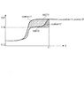
この酸素貯蔵能OSCは、触媒7の酸素貯蔵能力を表すものであり、その算出式として上式(3)を用いるのは、以下の理由による。図6は、第1および第2LAFセンサ12、13のゲインが互いに一致している場合の動作例を示している。図中のt1は、第2還元剤量積算値sumkact2が所定値krefを超えたタイミングを示す。前述したように、第1還元剤量積算値sumkact1は、排ガス還元制御中に触媒7に流入した還元剤の総量を表し、第2還元剤量積算値sumkact2は、排ガス還元制御中に触媒7を通過した還元剤の総量を表す。このため、両者の差は、還元雰囲気の排ガスが触媒7を通過した際、触媒7に貯蔵されていた酸素によって酸化された還元剤の総量を表し、すなわち、酸素貯蔵能OSCに相当する。したがって、第1および第2LAFセンサ12、13のゲインが互いに一致している場合には、酸素貯蔵能OSCは、次式(4)によって表される。
![]()
![]()
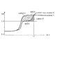
一方、第1および第2LAFセンサ12、13のゲインが互いにずれていて、例えば後者の方が高い場合には、図7に示すように、第2当量比KACT2の傾きが大きくなり、早く立ち上がるため、酸素貯蔵能OSCは、式(4)によって算出すると、過小な値になる。この場合、第1および第2当量比平均値avekact1、avekact2は、第1および第2当量比KACT2が定常状態に達した後のそれぞれの平均値であるので、図6に示すように、本来、互いに一致すべきものであり、図7のように一致していない場合には、第1および第2LAFセンサ12、13のゲインの大きさに対応する。
On the other hand, when the gains of the first and
したがって、前記式(3)の右辺の第1項の第1還元剤量積算値sumkact1と第1当量比平均値avekact1との比、および第2項の第2還元剤量積算値sumkact2と第2当量比平均値avekact2との比はそれぞれ、第1還元剤量積算値sumkact1および第2還元剤量積算値sumkact2を、第1および第2LAFセンサ12、13のゲインが互いに合致するようにゲイン補正した値に相当する。そして、式(3)によれば、そのようにゲイン補正された後の第1還元剤量積算値sumkact1と第2還元剤量積算値sumkact2との差として、酸素貯蔵能OSCを算出するので、両LAFセンサ12、13のゲインのずれを補償しながら、酸素貯蔵能OSCを適切に求めることができる。
Therefore, the ratio between the first reducing agent amount integrated value sumkact1 and the first equivalent ratio average value avekact1 in the first term on the right side of the equation (3), and the second reducing agent amount integrated value sumkact2 and the second term in the second term. The ratio to the equivalent ratio average value avekact2 was gain-corrected so that the gains of the first and
前記ステップ41に続くステップ42では、算出した酸素貯蔵能OSCが所定の判定値OSCJUDよりも大きいか否かを判別する。この判別結果がYESのときには、触媒7が劣化していないとし、そのことを表すために、触媒劣化フラグF_CATNGを「0」にセットした(ステップ43)後、本処理を終了する。
In
一方、ステップ42の判別結果がNOのときには、触媒7が劣化しているとし、そのことを表すために、触媒劣化フラグF_CATNGを「1」にセットした(ステップ44)後、本処理を終了する。
On the other hand, when the determination result in
以上のように、本実施形態によれば、排ガスを酸化雰囲気から還元雰囲気に切り換えた排ガス還元制御中、触媒7に流入した還元剤の総量を第1還元剤量積算値sumkact1として算出し、触媒7を通過した還元剤の総量を第2還元剤量積算値sumkact2として算出する。また、定常状態に達した後の第1および第2当量比KACT2をそれぞれ表す第1および第2当量比平均値avekact1、avekact2を算出する。
As described above, according to the present embodiment, during the exhaust gas reduction control in which the exhaust gas is switched from the oxidizing atmosphere to the reducing atmosphere, the total amount of the reducing agent that has flowed into the
そして、式(3)により、算出した第1還元剤量積算値sumkact1と第1当量比平均値avekact1との比、および第2還元剤量積算値sumkact2と第2当量比平均値avekact2との比を算出することによって、第1還元剤量積算値sumkact1および第2還元剤量積算値sumkactをゲイン補正するとともに、ゲイン補正された後の第1還元剤量積算値sumkact1と第2還元剤量積算値sumkact2との差として、酸素貯蔵能OSCを算出する。したがって、第1および第2LAFセンサ12、13のゲインのずれを補償しながら、酸素貯蔵能OSCを適切に算出することができる。その結果、第1および第2LAFセンサ12、13のゲインのずれの影響を受けることなく、算出した酸素貯蔵能OSCに基づいて、触媒7の劣化判定を適切に行うことができ、判定精度を向上させることができる。
Then, the ratio between the calculated first reducing agent amount integrated value sumkact1 and the first equivalent ratio average value avekact1, and the ratio between the second reducing agent amount integrated value sumkact2 and the second equivalent ratio average value avekact2 according to Equation (3). Is calculated, the first reducing agent amount integrated value sumkact1 and the second reducing agent amount integrated value sumkact are gain-corrected, and the first reducing agent amount integrated value sumkact1 and the second reducing agent amount integrated after the gain correction are performed. The oxygen storage capacity OSC is calculated as the difference from the value sumkact2. Therefore, it is possible to appropriately calculate the oxygen storage capacity OSC while compensating for the shift in the gain of the first and
また、第1および第2還元剤量積算値sumkact1、sumkact2の差として、酸素貯蔵能OSCを算出するので、第1および第2LAFセンサ12、13の出力値の一時的な変動や誤差による影響を適切に吸収でき、それにより、判定精度をさらに向上させることができる。
Further, since the oxygen storage capacity OSC is calculated as the difference between the first and second reducing agent amount integrated values sumkact1 and sumkact2, the influence of temporary fluctuations and errors in the output values of the first and
図8および図9は、図5の処理に代えて実行される、触媒劣化フラグF_CATNGの設定処理の2つの変形例をそれぞれ示している。これらの変形例は、触媒7の酸素貯蔵能OSCの算出方法が異なるものである。
FIGS. 8 and 9 show two modified examples of the catalyst deterioration flag F_CATNG setting process executed in place of the process of FIG. In these modified examples, the calculation method of the oxygen storage capacity OSC of the
図8の例では、酸素貯蔵能OSCを、次式(5)によって算出する(ステップ51)。
![]()
![]()
次いで、算出した酸素貯蔵能OSCが所定の判定値OSCJUD2よりも大きいか否かを判別し(ステップ52)、その判別結果に応じて、触媒劣化フラグF_CATNGを「0」または「1」にセットし(ステップ43、44)、本処理を終了する。 Next, it is determined whether or not the calculated oxygen storage capacity OSC is larger than a predetermined determination value OSCJUD2 (step 52), and the catalyst deterioration flag F_CATNG is set to “0” or “1” depending on the determination result. (Steps 43 and 44), this processing is terminated.
以上のように上流側の第1LAFセンサ12の出力値を基準とした場合には、触媒7での反応による排ガスの組成や活性度合の変化などによる影響を受けていない排ガスを対象とした第1LAFセンサ12の検出結果に基づき、第1および第2還元剤量積算値sumkact1、sumkact2と酸素貯蔵能OSCを適切に算出することができる。
As described above, when the output value of the
また、図9の変形例は、上記とは逆に、酸素貯蔵能OSCを、第2LAFセンサ13の出力値を基準として求めるものであり、酸素貯蔵能OSCは、次式(7)によって算出される(ステップ61)。
この式(7)は、前記式(3)の右辺に第2当量比平均値avekact2をさらに乗算したものであり、次式(8)のように書き換えられることから、第2LAFセンサ13の出力値を基準として、第1還元剤量積算値sumkact1をゲイン補正し、酸素貯蔵能OSCを算出するものである。
![]()
![]()
このように下流側の第2LAFセンサ13の出力値を基準とした場合には、内燃機関の冷間始動後などにおいて、排ガスの活性度合が低いために、上流側の第1LAFセンサ12の出力が鈍くなるようなときに、触媒7での反応により活性度合が高められた排ガスを対象とした第2LAFセンサ13の検出結果に基づき、第1および第2還元剤量積算値sumkact1、sumkact2と酸素貯蔵能OSCを適切に算出することができる。
As described above, when the output value of the downstream
次に、図10〜図13を参照しながら、第2実施形態による触媒の劣化判定装置21について説明する。なお、本実施形態において、前述した第1実施形態と同じ構成要素および制御処理の実行内容については、同じ参照番号を付し、その詳細な説明は省略するものとする。
Next, the catalyst
図10に示すように、このエンジン3の排気管5には、第1実施形態と同様、三元触媒で構成された触媒7が、上流側触媒として設けられるとともに、その下流側には、下流側触媒8が設けられている。この下流側触媒8は、NOx触媒で構成されており、酸化雰囲気の排ガスが流入したときに、排ガス中のNOxを捕捉する能力と、排ガス中の酸素を貯蔵する酸素貯蔵能力を有している。
As shown in FIG. 10, the
また、第1実施形態と同様、排気管5の触媒7よりも上流側には第1LAFセンサ12が設けられ、触媒7の下流側、すなわち触媒7と下流側触媒8との間には、第2LAFセンサ13が設けられている。さらに、下流側触媒8の下流側には、第3LAFセンサ14が設けられている。この第3LAFセンサ14もまた、ジルコニアなどで構成されており、広範囲な空燃比の領域において、下流側触媒8の下流側における排ガス中の酸素濃度をリニアに検出し、その検出信号をECU2に出力する。ECU2は、この第3LAFセンサ14の検出信号に基づいて、下流側触媒8の下流側における排ガス中の還元剤と酸素との質量比(燃空比)を換算した第3当量比KACT3を算出する。
As in the first embodiment, a
本実施形態では、触媒7および下流側触媒8の双方について、劣化判定が行われる。図11は、その劣化判定処理を示すフローチャートである。なお、この劣化判定処理を実行するに際し、排ガスを酸化雰囲気から還元雰囲気に切り換える排ガス還元制御を行うことは、第1実施形態と同様である。
In the present embodiment, the deterioration determination is performed for both the
本処理では、まず、第1実施形態における図2の処理と同様、判定条件成立フラグF_JUDが「1」であり(ステップ1:YES)、かつ第2還元剤量積算値sumkact2≦所定値krefのときに(ステップ2:NO)、第1および第2還元剤量積算値sumkact1、sumkact2を算出する(ステップ3および4)。それらの算出は、図3および図4の算出処理により、第1実施形態と同様にして行われる。
In this process, first, as in the process of FIG. 2 in the first embodiment, the determination condition satisfaction flag F_JUD is “1” (step 1: YES), and the second reducing agent amount integrated value sumkact2 ≦ predetermined value kref. Sometimes (step 2: NO), the first and second reducing agent amount integrated values sumkact1, sumkact2 are calculated (
次に、第3還元剤量積算値sumkact3を算出し(ステップ71)、本処理を終了する。この第3還元剤量積算値sumkact3は、排ガス還元制御中に下流側触媒8を通過した還元剤の総量を表すものであり、図12に示すサブルーチンにより、第1還元剤量積算値sumkact1などの場合と同様にして算出される。
Next, a third reducing agent amount integrated value sumkact3 is calculated (step 71), and this process is terminated. This third reducing agent amount integrated value sumkact3 represents the total amount of reducing agent that has passed through the
具体的には、第3当量比KACT3と値1.0との偏差(=KACT3−1.0)を、第3偏差DK3として算出し(ステップ81)、この第3偏差DK3が値0よりも大きいか否かを判別する(ステップ82)。この判別結果がNOのときには、第3還元剤量積算値sumkact3を値0にリセットする(ステップ83)。一方、この判別結果がYESのときには、第3偏差DK3および吸入空気量GAIRを用い、次式(9)に従って、第3還元剤量積算値sumkact3を算出し(ステップ84)、本処理を終了する。
![]()
![]()
以上のように、第3還元剤量積算値sumkact3は、DK3>0すなわちKACT3>1.0であるときに、第3偏差DK3と吸入空気量GAIRとの積を積算することによって算出されるので、排ガス還元制御中に下流側触媒8を通過した還元剤の総量に相当する。
As described above, the third reducing agent amount integrated value sumkact3 is calculated by integrating the product of the third deviation DK3 and the intake air amount GAIR when DK3> 0, that is, KACT3> 1.0. This corresponds to the total amount of reducing agent that has passed through the
図11に戻り、第2還元剤量積算値sumkact2>所定値krefのときには(ステップ2:YES)、第1実施形態と同様、ステップ5〜8を実行することにより、定常状態に達した後の第1当量比KACT1に基づいて、第1当量比平均値avekact1を算出するとともに、定常状態に達した後の第2当量比KACT2に基づいて、第2当量比平均値avekact2を算出する。
Returning to FIG. 11, when the second reducing agent amount integrated value sumkact2> predetermined value kref (step 2: YES), as in the first embodiment, by executing
次に、第3当量比変化量DKACT3が所定値KREF3よりも小さいか否かを判別する(ステップ72)。この第3当量比変化量DKACT3は、第3当量比の今回値と前回値との差の絶対値(=|KACT3−KACT3Z|)として算出される。この判別結果がYESのときには、第3当量比KACT3が定常状態に達したとして、第3当量比KACT3の平均値(以下「第3当量比平均値」という)avekact3を算出する(ステップ73)。この第3当量比平均値avekact3の算出は、前述した第1当量比平均値avekact1などの場合と同様、DKACT3<KREF3が成立した後に得られたn個の第3当量比KACT3を相加平均することによって、算出される。また、その算出が終了したときに、第3平均演算終了フラグF_AVE3が「1」にセットされる。 Next, it is determined whether or not the third equivalent ratio change amount DKACT3 is smaller than a predetermined value KREF3 (step 72). The third equivalent ratio change amount DKACT3 is calculated as an absolute value (= | KACT3-KACT3Z |) of the difference between the current value and the previous value of the third equivalent ratio. If the determination result is YES, assuming that the third equivalent ratio KACT3 has reached a steady state, an average value (hereinafter referred to as “third equivalent ratio average value”) avekact3 of the third equivalent ratio KACT3 is calculated (step 73). The calculation of the third equivalent ratio average value avekact3 is an arithmetic average of n third equivalent ratios KACT3 obtained after DKACT3 <KREF3 is established, as in the case of the first equivalent ratio average value avekact1 described above. Is calculated. When the calculation is completed, the third average calculation end flag F_AVE3 is set to “1”.
前記ステップ73に続くステップ74では、第1〜第3平均演算終了フラグF_AVE1〜3がいずれも「1」であるか否かを判別する。この判別結果がNOのときには、そのまま本処理を終了する。
In
一方、ステップ74の判別結果がYESで、第1〜第3当量比平均値avekact1〜3のすべての算出が終了しているときには、第1〜第3平均値演算終了フラグF_AVE1〜3をいずれも「0」にリセットした(ステップ75)後、触媒劣化フラグF_CATNGの設定処理を実行し(ステップ76)、本処理を終了する。
On the other hand, when the determination result in
図13は、この触媒劣化フラグF_CATNGの設定処理を示すサブルーチンを示している。本処理では、まず、第1実施形態における図5の処理とまったく同様にして、ステップ41〜44において、前記式(3)により算出された触媒7の酸素貯蔵能OSCと判定値OSCJUDとの比較結果に基づいて、触媒7の劣化を判定する。
FIG. 13 shows a subroutine showing the process for setting the catalyst deterioration flag F_CATNG. In this process, first, in exactly the same way as the process of FIG. 5 in the first embodiment, in
次に、下流側触媒8の酸素貯蔵能OSCrを、次式(10)によって算出する(ステップ91)。
![]()
![]()
次に、算出した酸素貯蔵能OSCrが、下流側触媒用の所定の判定値OSCJUDrよりも大きいか否かを判別する(ステップ92)。この判別結果がYESのときには、下流側触媒8が劣化していないとし、そのことを表すために、下流側触媒用の触媒劣化フラグF_CATRNGを「0」にセットした(ステップ93)後、本処理を終了する。
Next, it is determined whether or not the calculated oxygen storage capacity OSCr is larger than a predetermined determination value OSCJUDr for the downstream catalyst (step 92). When the determination result is YES, it is determined that the
一方、ステップ92の判別結果がNOのときには、下流側触媒8が劣化しているとし、そのことを表すために、触媒劣化フラグF_CATRNGを「1」にセットした(ステップ94)後、本処理を終了する。
On the other hand, when the determination result in
以上のように、本実施形態によれば、排ガス還元制御中、触媒7の上流側および触媒7と下流側触媒8との中間にそれぞれ設けられた第1および第2LAFセンサ12、13の検出結果に基づき、第1実施形態と同様にして、触媒7の酸素貯蔵能OSCを算出するとともに、第2LAFセンサ12および下流側触媒8の下流側に設けられた第3LAFセンサ14の検出結果に基づき、触媒7の酸素貯蔵能OSCと同様にして、下流側触媒8の酸素貯蔵能OSCrを算出する。したがって、第1〜第3LAFセンサ12〜14のゲインのずれを補償しながら、触媒7の酸素貯蔵能OSCおよび下流側触媒8の酸素貯蔵能OSCrを適切に算出することができる。その結果、第1〜第3LAFセンサ12〜14のゲインのずれの影響を受けることなく、算出した酸素貯蔵能OSCおよび酸素貯蔵能OSCrに基づいて、触媒7および下流側触媒8の劣化判定を適切に行うことができ、判定精度を向上させることができる。
As described above, according to the present embodiment, during the exhaust gas reduction control, the detection results of the first and
なお、本発明は、説明した実施形態に限定されることなく、種々の態様で実施することができる。例えば、実施形態では、酸素濃度パラメータとして、第1〜第3当量比KACT1〜KACT3を用いているが、排ガス中の酸素濃度を表すパラメータであれば、他の任意のパラメータを用いてもよい。例えば、排ガス中のHCやCOなどの還元剤の濃度は、酸素濃度と相関性を有するので、酸素濃度パラメータとして用いることが可能である。 In addition, this invention can be implemented in various aspects, without being limited to the described embodiment. For example, in the embodiment, the first to third equivalent ratios KACT1 to KACT3 are used as the oxygen concentration parameter, but any other parameter may be used as long as the parameter represents the oxygen concentration in the exhaust gas. For example, the concentration of a reducing agent such as HC or CO in the exhaust gas has a correlation with the oxygen concentration and can be used as an oxygen concentration parameter.
また、実施形態では、排ガスを還元雰囲気に切り換えた後に所定期間が経過したか否かを定めるための第1〜第3当量比KACT1〜KACT3の定常状態の判定を、それぞれの今回値と前回値との差の絶対値として求めた当量比変化量DKACT1〜KACT3を所定値KREF1〜KREF3と比較することによって行っているが、他の適当な手法で行ってもよい。例えば、排ガスを還元雰囲気に切り換えた後の経過時間、あるいは第1〜第3当量比KACT1〜KACT3がそれぞれ値1.0を超えた後の経過時間をタイマで計測し、計測された経過時間が所定時間に達したときに、第1〜第3当量比KACT1〜KACT3が定常状態に達したと判定してもよい。 Further, in the embodiment, the determination of the steady state of the first to third equivalent ratios KACT1 to KACT3 for determining whether or not the predetermined period has elapsed after switching the exhaust gas to the reducing atmosphere is performed for each of the current value and the previous value. The equivalent ratio change amounts DKACT1 to KACT3 obtained as absolute values of the difference between the values are compared with the predetermined values KREF1 to KREF3. However, other appropriate methods may be used. For example, the elapsed time after switching the exhaust gas to the reducing atmosphere, or the elapsed time after each of the first to third equivalent ratios KACT1 to KACT3 exceeds 1.0 is measured with a timer, and the measured elapsed time When the predetermined time is reached, it may be determined that the first to third equivalent ratios KACT1 to KACT3 have reached a steady state.
さらに、実施形態では、排ガスを酸化雰囲気から還元雰囲気に切り換える排ガス還元制御を、燃焼室3aへの燃料噴射量を制御することによって行っているが、還元剤としての燃料や尿素などを、排気管5の第1LAFセンサ12よりも上流側に直接、供給することによって行ってもよい。あるいは、排ガス還元制御に代えて、排ガスを還元雰囲気から酸化雰囲気に切り換えた状態で、劣化判定を行ってもよい。
Furthermore, in the embodiment, the exhaust gas reduction control for switching the exhaust gas from the oxidizing atmosphere to the reducing atmosphere is performed by controlling the amount of fuel injected into the
また、第1実施形態は、触媒7が三元触媒の例であり、第2実施形態は、上流側の触媒7が三元触媒、下流側触媒8がNOx触媒の例であるが、触媒が酸素貯蔵能力を有するものであれば、そのタイプや、配置および数を任意に変更することが可能である。
The first embodiment is an example in which the
さらに、第2実施形態では、下流側触媒8の酸素貯蔵能OSCrの算出を、式(3)に相当する式(10)を用いて行っているが、これに代えて、第1実施形態の変形例による式(5)や式(7)に相当する式を用いてもよい。
Furthermore, in the second embodiment, the oxygen storage capacity OSCr of the
また、実施形態は、本発明を車両に搭載されたディーゼルエンジンに適用した例であるが、本発明は、これに限らず、ディーゼルエンジン以外のガソリンエンジンなどの各種のエンジンに適用してもよく、また、車両用以外のエンジン、例えば、クランク軸を鉛直に配置した船外機などのような船舶推進機用エンジンにも適用可能である。その他、本発明の趣旨の範囲内で、細部の構成を適宜、変更することが可能である。 Moreover, although embodiment is an example which applied this invention to the diesel engine mounted in the vehicle, this invention is not restricted to this, You may apply to various engines, such as gasoline engines other than a diesel engine. Also, the present invention can be applied to engines other than those for vehicles, for example, engines for marine propulsion devices such as outboard motors having a crankshaft arranged vertically. In addition, it is possible to appropriately change the detailed configuration within the scope of the gist of the present invention.
1 劣化判定装置
2 ECU(制御手段、補正手段、劣化判定手段、積算値算出手段および定常状態判定
手段)
3 内燃機関
5 排気管(排気通路)
7 触媒(上流側触媒)
8 下流側触媒
12 第1LAFセンサ(第1酸素濃度パラメータセンサ)
13 第2LAFセンサ(第2酸素濃度パラメータセンサ)
14 第3LAFセンサ(第3酸素濃度パラメータセンサ)
21 劣化判定装置
KACT1 第1当量比(上流側酸素濃度パラメータ)
KACT2 第2当量比(下流側酸素濃度パラメータ、中間酸素濃度パラメータ)
KACT3 第3当量比(下流側酸素濃度パラメータ)
sumkact1 第1還元剤量積算値(上流側酸素濃度パラメータの積算値)
sumkact2 第2還元剤量積算値(下流側酸素濃度パラメータの積算値、中間酸素
濃度パラメータの積算値)
sumkact3 第3還元剤量積算値(下流側酸素濃度パラメータの積算値)
avekact1 第1当量比平均値(所定期間以降に検出された上流側酸素濃度パラメ
ータ)
avekact2 第2当量比平均値(所定期間以降に検出された下流側酸素濃度パラメ
ータ、中間酸素濃度パラメータ)
avekact3 第3当量比平均値(所定期間以降に検出された下流側酸素濃度パラメ
ータ)
1
3
7 Catalyst (Upstream catalyst)
8
13 Second LAF sensor (second oxygen concentration parameter sensor)
14 Third LAF sensor (third oxygen concentration parameter sensor)
21 Degradation determination device KACT1 first equivalent ratio (upstream oxygen concentration parameter)
KACT2 second equivalent ratio (downstream oxygen concentration parameter, intermediate oxygen concentration parameter)
KACT3 3rd equivalent ratio (downstream oxygen concentration parameter)
sumkact1 first reducing agent amount integrated value (integrated value of upstream oxygen concentration parameter)
sumkact2 second reducing agent amount integrated value (integrated value of downstream oxygen concentration parameter, intermediate oxygen
Integrated value of concentration parameter)
sumkact3 third reducing agent amount integrated value (integrated value of downstream oxygen concentration parameter)
avekact1 first equivalent ratio average value (upstream oxygen concentration parameters detected after a predetermined period)
Data)
avekact2 second equivalent ratio average (downstream oxygen concentration parameter detected after a predetermined period)
And intermediate oxygen concentration parameters)
avekact3 third equivalence ratio average value (downstream oxygen concentration parameters detected after a predetermined period)
Data)
Claims (8)
前記触媒の上流側における排ガス中の酸素濃度を表す上流側酸素濃度パラメータを検出する第1酸素濃度パラメータセンサと、
前記触媒の下流側における排ガス中の酸素濃度を表す下流側酸素濃度パラメータを検出する第2酸素濃度パラメータセンサと、
前記触媒に流入する排ガスを酸化雰囲気と還元雰囲気の間で切り換えて制御する制御手段と、
当該制御手段により排ガスが切り換えられた後に検出された前記上流側酸素濃度パラメータおよび前記下流側酸素濃度パラメータを、当該排ガスの切換時から所定期間が経過した以降に検出された前記上流側酸素濃度パラメータおよび前記下流側酸素濃度パラメータが互いに合致するように補正する補正手段と、
当該補正された上流側酸素濃度パラメータおよび下流側酸素濃度パラメータの相互の比較結果に基づいて、前記触媒の劣化を判定する劣化判定手段と、
を備えることを特徴とする触媒の劣化判定装置。 A catalyst deterioration determination device provided in an exhaust passage of an internal combustion engine and having an oxygen storage capacity for purifying exhaust gas and storing oxygen,
A first oxygen concentration parameter sensor for detecting an upstream oxygen concentration parameter representing an oxygen concentration in exhaust gas upstream of the catalyst;
A second oxygen concentration parameter sensor for detecting a downstream oxygen concentration parameter representing an oxygen concentration in the exhaust gas on the downstream side of the catalyst;
Control means for switching and controlling the exhaust gas flowing into the catalyst between an oxidizing atmosphere and a reducing atmosphere;
The upstream oxygen concentration parameter and the downstream oxygen concentration parameter detected after the exhaust gas is switched by the control means, the upstream oxygen concentration parameter detected after a predetermined period has elapsed since the switching of the exhaust gas. And correction means for correcting the downstream oxygen concentration parameters so as to match each other,
A deterioration determining means for determining deterioration of the catalyst based on a comparison result between the corrected upstream oxygen concentration parameter and the downstream oxygen concentration parameter;
An apparatus for determining deterioration of a catalyst, comprising:
前記補正手段は、前記算出された上流側酸素濃度パラメータの積算値と前記所定期間以降に検出された前記上流側酸素濃度パラメータとの比、および前記算出された下流側酸素濃度パラメータの積算値と前記所定期間以降に検出された前記下流側酸素濃度パラメータとの比を算出することによって、前記上流側酸素濃度パラメータの積算値および前記下流側酸素濃度パラメータの積算値をそれぞれ補正し、
前記劣化判定手段は、前記補正された上流側酸素濃度パラメータの積算値および下流側酸素濃度パラメータの積算値の相互の比較結果に基づいて、前記触媒の劣化を判定することを特徴とする、請求項1に記載の触媒の劣化判定装置。 An integrated value calculating means for calculating integrated values of the upstream oxygen concentration parameter and the downstream oxygen concentration parameter detected within the predetermined period,
The correction means includes a ratio between the calculated integrated value of the upstream oxygen concentration parameter and the upstream oxygen concentration parameter detected after the predetermined period, and the calculated integrated value of the downstream oxygen concentration parameter. By calculating a ratio with the downstream oxygen concentration parameter detected after the predetermined period, the integrated value of the upstream oxygen concentration parameter and the integrated value of the downstream oxygen concentration parameter are respectively corrected,
The deterioration determination unit determines deterioration of the catalyst based on a comparison result between the corrected integrated value of the upstream oxygen concentration parameter and the integrated value of the downstream oxygen concentration parameter. Item 2. The catalyst deterioration determination device according to Item 1.
前記所定期間は、前記排ガスの切換後、前記上流側酸素濃度パラメータおよび前記下流側酸素濃度パラメータの両方が定常状態に達したと判定されるまでの期間であることを特徴とする、請求項1ないし3のいずれかに記載の触媒の劣化判定装置。 Steady state determination means for determining whether or not the upstream oxygen concentration parameter and the downstream oxygen concentration parameter have reached a steady state;
The predetermined period is a period until it is determined that both the upstream oxygen concentration parameter and the downstream oxygen concentration parameter have reached a steady state after switching the exhaust gas. 4. The catalyst deterioration determination device according to any one of items 3 to 3.
前記上流側触媒の上流側における排ガス中の酸素濃度を表す上流側酸素濃度パラメータを検出する第1酸素濃度パラメータセンサと、
前記上流側触媒と前記下流側触媒との中間における排ガス中の酸素濃度を表す中間酸素濃度パラメータを検出する第2酸素濃度パラメータセンサと、
前記下流側触媒の下流側における排ガス中の酸素濃度を表す下流側酸素濃度パラメータを検出する第3酸素濃度パラメータセンサと、
前記上流側触媒に流入する排ガスを酸化雰囲気と還元雰囲気の間で切り換えて制御する制御手段と、
当該制御手段により排ガスが切り換えられた後に検出された前記上流側酸素濃度パラメータ、前記中間酸素濃度パラメータおよび前記下流側酸素濃度パラメータを、当該排ガスの切換時から所定期間が経過した以降に検出された前記上流側酸素濃度パラメータ、前記中間酸素濃度パラメータおよび前記下流側酸素濃度パラメータが互いに合致するように補正する補正手段と、
当該補正された上流側酸素濃度パラメータ、中間酸素濃度パラメータおよび下流側酸素濃度パラメータの相互の比較結果に基づいて、前記上流側触媒および前記下流側触媒の劣化を判定する劣化判定手段と、
を備えることを特徴とする触媒の劣化判定装置。 An exhaust gas provided in an exhaust passage of an internal combustion engine for purifying exhaust gas and determining deterioration of an upstream catalyst having an oxygen storage capacity for storing oxygen, and provided at a downstream side of the upstream catalyst in the exhaust passage, Is a catalyst deterioration determination device for determining deterioration of a downstream catalyst having an oxygen storage capacity for purifying gas and storing oxygen,
A first oxygen concentration parameter sensor for detecting an upstream oxygen concentration parameter representing an oxygen concentration in exhaust gas upstream of the upstream catalyst;
A second oxygen concentration parameter sensor for detecting an intermediate oxygen concentration parameter representing an oxygen concentration in the exhaust gas between the upstream catalyst and the downstream catalyst;
A third oxygen concentration parameter sensor for detecting a downstream oxygen concentration parameter representing an oxygen concentration in the exhaust gas on the downstream side of the downstream catalyst;
Control means for switching and controlling the exhaust gas flowing into the upstream catalyst between an oxidizing atmosphere and a reducing atmosphere;
The upstream oxygen concentration parameter, the intermediate oxygen concentration parameter, and the downstream oxygen concentration parameter detected after the exhaust gas is switched by the control means are detected after a predetermined period has elapsed since the switching of the exhaust gas. Correction means for correcting the upstream oxygen concentration parameter, the intermediate oxygen concentration parameter, and the downstream oxygen concentration parameter to match each other;
A deterioration determination means for determining deterioration of the upstream catalyst and the downstream catalyst based on a comparison result of the corrected upstream oxygen concentration parameter, intermediate oxygen concentration parameter, and downstream oxygen concentration parameter;
An apparatus for determining deterioration of a catalyst, comprising:
前記補正手段は、前記算出された上流側酸素濃度パラメータの積算値と前記所定期間以降に検出された前記上流側酸素濃度パラメータとの比、前記算出された中間素濃度パラメータの積算値と前記所定期間以降に検出された前記中間酸素濃度パラメータとの比、および前記算出された下流側酸素濃度パラメータの積算値と前記所定期間以降に検出された前記下流側酸素濃度パラメータとの比を算出することによって、前記上流側酸素濃度パラメータの積算値、前記中間酸素濃度パラメータの積算値、および前記下流側酸素濃度パラメータの積算値をそれぞれ補正し、
前記劣化判定手段は、前記補正された上流側酸素濃度パラメータの積算値、中間酸素濃度パラメータの積算値、および下流側酸素濃度パラメータの積算値の相互の比較結果に基づいて、前記上流側触媒および前記下流側触媒の劣化を判定することを特徴とする、請求項5に記載の触媒の劣化判定装置。 Further comprising integrated value calculating means for calculating integrated values of the upstream oxygen concentration parameter, the intermediate oxygen concentration parameter, and the downstream oxygen concentration parameter detected within the predetermined period,
The correction means includes a ratio between the calculated upstream oxygen concentration parameter integrated value and the upstream oxygen concentration parameter detected after the predetermined period, the calculated intermediate element concentration parameter integrated value and the predetermined value. Calculating a ratio between the intermediate oxygen concentration parameter detected after a period and a ratio between the integrated value of the calculated downstream oxygen concentration parameter and the downstream oxygen concentration parameter detected after the predetermined period By correcting the integrated value of the upstream oxygen concentration parameter, the integrated value of the intermediate oxygen concentration parameter, and the integrated value of the downstream oxygen concentration parameter, respectively,
The deterioration determining means is configured to determine whether the upstream catalyst and the upstream catalyst and the intermediate oxygen concentration parameter integrated value, the intermediate oxygen concentration parameter integrated value, and the downstream oxygen concentration parameter integrated value are mutually compared. 6. The catalyst deterioration determination apparatus according to claim 5, wherein deterioration of the downstream catalyst is determined.
前記所定期間は、前記排ガスの切換後、前記上流側酸素濃度パラメータ、前記中間酸素濃度パラメータおよび前記下流側酸素濃度パラメータのいずれもが定常状態に達したと判定されるまでの期間であることを特徴とする、請求項5ないし7のいずれかに記載の触媒の劣化判定装置。 A steady state determination means for determining whether the upstream oxygen concentration parameter, the intermediate oxygen concentration parameter, and the downstream oxygen concentration parameter have reached a steady state;
The predetermined period is a period until it is determined that all of the upstream oxygen concentration parameter, the intermediate oxygen concentration parameter, and the downstream oxygen concentration parameter have reached a steady state after switching the exhaust gas. The catalyst deterioration determination device according to any one of claims 5 to 7, characterized in that it is characterized in that:
Priority Applications (4)
| Application Number | Priority Date | Filing Date | Title |
|---|---|---|---|
| JP2008161491A JP4637213B2 (en) | 2008-06-20 | 2008-06-20 | Catalyst deterioration judgment device |
| US12/482,694 US8186147B2 (en) | 2008-06-20 | 2009-06-11 | Catalyst deterioration-determination device and method and engine control unit |
| EP09162611A EP2133531B1 (en) | 2008-06-12 | 2009-06-12 | Catalyst deterioration-determination device and method |
| AT09162611T ATE519026T1 (en) | 2008-06-12 | 2009-06-12 | CATALYST DECOMPOSITION DETERMINATION APPARATUS AND METHOD |
Applications Claiming Priority (1)
| Application Number | Priority Date | Filing Date | Title |
|---|---|---|---|
| JP2008161491A JP4637213B2 (en) | 2008-06-20 | 2008-06-20 | Catalyst deterioration judgment device |
Publications (2)
| Publication Number | Publication Date |
|---|---|
| JP2010001803A true JP2010001803A (en) | 2010-01-07 |
| JP4637213B2 JP4637213B2 (en) | 2011-02-23 |
Family
ID=41429842
Family Applications (1)
| Application Number | Title | Priority Date | Filing Date |
|---|---|---|---|
| JP2008161491A Expired - Fee Related JP4637213B2 (en) | 2008-06-12 | 2008-06-20 | Catalyst deterioration judgment device |
Country Status (2)
| Country | Link |
|---|---|
| US (1) | US8186147B2 (en) |
| JP (1) | JP4637213B2 (en) |
Cited By (1)
| Publication number | Priority date | Publication date | Assignee | Title |
|---|---|---|---|---|
| CN105508000A (en) * | 2014-10-13 | 2016-04-20 | 福特环球技术公司 | Integrated fuel catalyst monitor |
Families Citing this family (6)
| Publication number | Priority date | Publication date | Assignee | Title |
|---|---|---|---|---|
| FR2956988B1 (en) * | 2010-03-05 | 2012-04-06 | Peugeot Citroen Automobiles Sa | FILTERING DEVICE, PARTICULATE FILTER FOR THIS DEVICE, VEHICLE EQUIPPED WITH THE FILTER, DIAGNOSTIC METHOD FOR THE AGING OF THE FILTER AGING, RECORDING MEDIUM FOR THIS METHOD |
| JP5024405B2 (en) * | 2010-03-09 | 2012-09-12 | トヨタ自動車株式会社 | Catalyst degradation detector |
| JP5062307B2 (en) * | 2010-08-06 | 2012-10-31 | トヨタ自動車株式会社 | Catalyst degradation detector |
| WO2014045367A1 (en) * | 2012-09-20 | 2014-03-27 | トヨタ自動車株式会社 | Control device for internal combustion engine |
| JP6288011B2 (en) * | 2015-08-31 | 2018-03-07 | トヨタ自動車株式会社 | Internal combustion engine |
| JP6611397B2 (en) * | 2016-03-29 | 2019-11-27 | 本田技研工業株式会社 | Catalyst diagnostic device |
Citations (3)
| Publication number | Priority date | Publication date | Assignee | Title |
|---|---|---|---|---|
| JPH05133264A (en) * | 1991-11-12 | 1993-05-28 | Toyota Motor Corp | Detecting device for deterioration degree of catalyst |
| JP2001193521A (en) * | 1999-10-29 | 2001-07-17 | Denso Corp | Exhaust emission control device for internal combustion engine |
| US20070298504A1 (en) * | 2006-06-27 | 2007-12-27 | Torsten Wolfgang Mueller | Diesel exhaust treatment system catalyst monitoring |
Family Cites Families (9)
| Publication number | Priority date | Publication date | Assignee | Title |
|---|---|---|---|---|
| US5392599A (en) * | 1994-01-10 | 1995-02-28 | Ford Motor Company | Engine air/fuel control with adaptive correction of ego sensor output |
| JPH09203313A (en) * | 1995-11-20 | 1997-08-05 | Mazda Motor Corp | Degradation detecting device for catalyst |
| US5758494A (en) * | 1997-01-16 | 1998-06-02 | Ford Global Technologies, Inc. | System and method for adaptive switch determination of exhaust gas sensors |
| US6131439A (en) * | 1998-05-28 | 2000-10-17 | Ford Global Technologies, Inc. | Catalyst deterioration detection with sensor calibration |
| JP3592579B2 (en) | 1999-05-17 | 2004-11-24 | 本田技研工業株式会社 | Exhaust gas purification device for internal combustion engine |
| JP3625163B2 (en) * | 1999-11-08 | 2005-03-02 | 株式会社デンソー | Exhaust purification catalyst deterioration detection device |
| JP3922980B2 (en) * | 2001-07-25 | 2007-05-30 | 本田技研工業株式会社 | Control device |
| JP3873904B2 (en) | 2003-02-26 | 2007-01-31 | 日産自動車株式会社 | Exhaust gas purification device for internal combustion engine |
| JP4156630B2 (en) * | 2006-04-18 | 2008-09-24 | 三菱電機株式会社 | Catalyst deterioration diagnosis apparatus and catalyst deterioration diagnosis method for internal combustion engine |
-
2008
- 2008-06-20 JP JP2008161491A patent/JP4637213B2/en not_active Expired - Fee Related
-
2009
- 2009-06-11 US US12/482,694 patent/US8186147B2/en not_active Expired - Fee Related
Patent Citations (3)
| Publication number | Priority date | Publication date | Assignee | Title |
|---|---|---|---|---|
| JPH05133264A (en) * | 1991-11-12 | 1993-05-28 | Toyota Motor Corp | Detecting device for deterioration degree of catalyst |
| JP2001193521A (en) * | 1999-10-29 | 2001-07-17 | Denso Corp | Exhaust emission control device for internal combustion engine |
| US20070298504A1 (en) * | 2006-06-27 | 2007-12-27 | Torsten Wolfgang Mueller | Diesel exhaust treatment system catalyst monitoring |
Cited By (2)
| Publication number | Priority date | Publication date | Assignee | Title |
|---|---|---|---|---|
| CN105508000A (en) * | 2014-10-13 | 2016-04-20 | 福特环球技术公司 | Integrated fuel catalyst monitor |
| CN105508000B (en) * | 2014-10-13 | 2019-12-06 | 福特环球技术公司 | Integrated fuel catalyst monitor |
Also Published As
| Publication number | Publication date |
|---|---|
| JP4637213B2 (en) | 2011-02-23 |
| US8186147B2 (en) | 2012-05-29 |
| US20090313974A1 (en) | 2009-12-24 |
Similar Documents
| Publication | Publication Date | Title |
|---|---|---|
| US8151552B2 (en) | Deterioration determination device and method for exhaust emission reduction device, and engine control unit | |
| US8555614B2 (en) | Internal combustion engine exhaust gas control apparatus and abnormality determining method thereof | |
| JP4835497B2 (en) | Air-fuel ratio control device for internal combustion engine | |
| JP3941828B2 (en) | Air-fuel ratio control device for internal combustion engine | |
| JP5024676B2 (en) | Catalyst deterioration suppressor | |
| JP4497132B2 (en) | Catalyst degradation detector | |
| JP4637213B2 (en) | Catalyst deterioration judgment device | |
| JP2009203910A (en) | Air-fuel ratio control device for internal combustion engine | |
| JPWO2012039064A1 (en) | Air-fuel ratio control device for internal combustion engine | |
| US8205435B2 (en) | Deterioration determination device for catalyst, catalyst deterioration determining method, and engine control unit | |
| JP4890209B2 (en) | Exhaust gas purification device for internal combustion engine | |
| JP2007291912A (en) | Air fuel ratio control device for internal combustion engine | |
| JP5022997B2 (en) | Catalyst deterioration judgment device | |
| JP2009264184A (en) | Catalyst degradation diagnostic device | |
| JP4906793B2 (en) | Catalyst deterioration judgment device | |
| JP4072412B2 (en) | Air-fuel ratio control device for internal combustion engine | |
| JP5308870B2 (en) | Catalyst deterioration judgment device | |
| JP3601210B2 (en) | Engine air-fuel ratio control device | |
| EP2133531B1 (en) | Catalyst deterioration-determination device and method | |
| EP2133530B1 (en) | Deterioration determination device and method for exhaust emission reduction device | |
| JP2004108187A (en) | Deterioration diagnosis device of exhaust emission control catalyst for internal combustion engine | |
| JP3624689B2 (en) | Exhaust gas purification device for internal combustion engine | |
| JP2005090388A (en) | Exhaust emission purification controller for internal combustion engine | |
| JP4906804B2 (en) | Deterioration judgment device for exhaust gas purification device | |
| JP3610798B2 (en) | Air-fuel ratio control device for internal combustion engine |
Legal Events
| Date | Code | Title | Description |
|---|---|---|---|
| A977 | Report on retrieval |
Free format text: JAPANESE INTERMEDIATE CODE: A971007 Effective date: 20100408 |
|
| A131 | Notification of reasons for refusal |
Free format text: JAPANESE INTERMEDIATE CODE: A131 Effective date: 20100427 |
|
| A521 | Request for written amendment filed |
Free format text: JAPANESE INTERMEDIATE CODE: A523 Effective date: 20100628 |
|
| TRDD | Decision of grant or rejection written | ||
| A01 | Written decision to grant a patent or to grant a registration (utility model) |
Free format text: JAPANESE INTERMEDIATE CODE: A01 Effective date: 20101026 |
|
| A01 | Written decision to grant a patent or to grant a registration (utility model) |
Free format text: JAPANESE INTERMEDIATE CODE: A01 |
|
| A61 | First payment of annual fees (during grant procedure) |
Free format text: JAPANESE INTERMEDIATE CODE: A61 Effective date: 20101122 |
|
| FPAY | Renewal fee payment (event date is renewal date of database) |
Free format text: PAYMENT UNTIL: 20131203 Year of fee payment: 3 |
|
| R150 | Certificate of patent or registration of utility model |
Free format text: JAPANESE INTERMEDIATE CODE: R150 |
|
| LAPS | Cancellation because of no payment of annual fees |