JP2010000347A - Data inputting method and ultrasonic imaging device - Google Patents
Data inputting method and ultrasonic imaging device Download PDFInfo
- Publication number
- JP2010000347A JP2010000347A JP2009132198A JP2009132198A JP2010000347A JP 2010000347 A JP2010000347 A JP 2010000347A JP 2009132198 A JP2009132198 A JP 2009132198A JP 2009132198 A JP2009132198 A JP 2009132198A JP 2010000347 A JP2010000347 A JP 2010000347A
- Authority
- JP
- Japan
- Prior art keywords
- data
- ultrasonic
- input
- raw data
- imaging apparatus
- Prior art date
- Legal status (The legal status is an assumption and is not a legal conclusion. Google has not performed a legal analysis and makes no representation as to the accuracy of the status listed.)
- Granted
Links
- 238000003384 imaging method Methods 0.000 title claims abstract description 31
- 238000000034 method Methods 0.000 title claims abstract description 30
- 238000012545 processing Methods 0.000 claims abstract description 24
- 238000012856 packing Methods 0.000 claims abstract description 16
- 238000012285 ultrasound imaging Methods 0.000 claims description 15
- 238000002604 ultrasonography Methods 0.000 claims description 5
- 230000005540 biological transmission Effects 0.000 description 6
- 239000000523 sample Substances 0.000 description 5
- 238000010586 diagram Methods 0.000 description 3
- 230000002093 peripheral effect Effects 0.000 description 2
- 230000001360 synchronised effect Effects 0.000 description 2
- 238000012546 transfer Methods 0.000 description 2
- 239000005043 ethylene-methyl acrylate Substances 0.000 description 1
- 238000013507 mapping Methods 0.000 description 1
- 239000004065 semiconductor Substances 0.000 description 1
Images

Classifications
-
- G—PHYSICS
- G01—MEASURING; TESTING
- G01S—RADIO DIRECTION-FINDING; RADIO NAVIGATION; DETERMINING DISTANCE OR VELOCITY BY USE OF RADIO WAVES; LOCATING OR PRESENCE-DETECTING BY USE OF THE REFLECTION OR RERADIATION OF RADIO WAVES; ANALOGOUS ARRANGEMENTS USING OTHER WAVES
- G01S7/00—Details of systems according to groups G01S13/00, G01S15/00, G01S17/00
- G01S7/52—Details of systems according to groups G01S13/00, G01S15/00, G01S17/00 of systems according to group G01S15/00
- G01S7/52017—Details of systems according to groups G01S13/00, G01S15/00, G01S17/00 of systems according to group G01S15/00 particularly adapted to short-range imaging
- G01S7/52079—Constructional features
- G01S7/52082—Constructional features involving a modular construction, e.g. a computer with short range imaging equipment
Abstract
Description
本発明は、データ(data)入力方法および超音波イメージング(imaging)装置に関し、特に、超音波ローデータ(raw data)をプロセッサ(processor)に入力する方法、および、超音波ローデータをプロセッサで処理する超音波イメージング装置に関する。 The present invention relates to a data input method and an ultrasonic imaging apparatus, and more particularly, a method of inputting ultrasonic raw data to a processor, and processing ultrasonic raw data by a processor. The present invention relates to an ultrasonic imaging apparatus.
超音波イメージング装置の一形態に、ノートPC(note-type personal computer)に類似した、携帯型の超音波イメージング機器として構成されたものがある。この種の超音波イメージング装置は、病室へ回診時や病人宅への往診時に携行することができるので、利便性が高い(例えば、特許文献1参照)。 One form of the ultrasound imaging apparatus is configured as a portable ultrasound imaging apparatus similar to a notebook PC (note-type personal computer). This type of ultrasound imaging apparatus is highly convenient because it can be carried at the time of visiting a hospital room or visiting a sick person's home (see, for example, Patent Document 1).
超音波イメージング装置においては、リアルタイムイメージング(real time imaging)を可能にするために、プロセッサ(processor)への超音波ローデータの入力には、高いスループット(throughput)が求められる。このため、DMA(Direct Memory Access)やPCI(Peripheral Component Interconnect)等の高速のデータ転送システム(system)が利用される(例えば、特許文献2参照)。 In an ultrasonic imaging apparatus, in order to enable real time imaging, high throughput is required for inputting ultrasonic raw data to a processor. For this reason, a high-speed data transfer system (system) such as DMA (Direct Memory Access) or PCI (Peripheral Component Interconnect) is used (for example, see Patent Document 2).
携帯型の超音波イメージング装置では、内部スペース(space)や消費電力あるいはコスト上の制約により、DMAやPCI等の高速データ転送システムを装備することは極めて困難である。 In a portable ultrasonic imaging apparatus, it is extremely difficult to equip a high-speed data transfer system such as DMA or PCI due to internal space, power consumption, or cost constraints.
そこで、本発明の目的は、高速データ伝送システムによらずに超音波ローデータを高速にプロセッサに入力するデータ入力方法および超音波イメージング装置を実現することである。 Accordingly, an object of the present invention is to realize a data input method and an ultrasonic imaging apparatus that input ultrasonic raw data to a processor at high speed without using a high-speed data transmission system.
課題を解決するための手段としての本発明は、第1の観点では、超音波ローデータをプロセッサに入力する方法であって、超音波ローデータをプロセッサのビデオプロセッシング・フロントエンドに入力することを特徴とするデータ入力方法である。 In a first aspect, the present invention as means for solving the problem is a method of inputting ultrasonic raw data to a processor, wherein the ultrasonic raw data is input to a video processing front end of the processor. This is a featured data input method.
課題を解決するための手段としての本発明は、第2の観点では、前記超音波ローデータは、ベクトルデータとして入力されることを特徴とする第1の観点に記載のデータ入力方法である。 In a second aspect, the present invention as means for solving the problem is the data input method according to the first aspect, wherein the ultrasonic raw data is input as vector data.
課題を解決するための手段としての本発明は、第3の観点では、前記ベクトルデータは、前記超音波ローデータをパッキングして構成されることを特徴とする第2の観点に記載のデータ入力方法である。 According to a third aspect of the present invention, as the means for solving the problem, in the third aspect, the vector data is configured by packing the ultrasonic raw data, and the data input according to the second aspect Is the method.
課題を解決するための手段としての本発明は、第4の観点では、前記超音波ローデータのパッキングは、1PRTごとに行われることを特徴とする第3の観点に記載のデータ入力方法である。 The present invention as means for solving the problem is the data input method according to the third aspect, wherein, in a fourth aspect, the packing of the ultrasonic raw data is performed for each PRT. .
課題を解決するための手段としての本発明は、第5の観点では、前記ベクトルデータは、同期信号とともに入力されることを特徴とする第2の観点に記載のデータ入力方法である。 The present invention as means for solving the problem is, in a fifth aspect, the data input method according to the second aspect, wherein the vector data is input together with a synchronization signal.
課題を解決するための手段としての本発明は、第6の観点では、前記同期信号は、1ベクトルデータごとに入力されることを特徴とする第5の観点に記載のデータ入力方法である。 The present invention as means for solving the problem, in a sixth aspect, is the data input method according to the fifth aspect, wherein the synchronization signal is input for each vector data.
課題を解決するための手段としての本発明は、第7の観点では、前記同期信号は、垂直同期信号および水平同期信号を含むことを特徴とする第6の観点に記載のデータ入力方法である。 The present invention as means for solving the problem is, in a seventh aspect, the data input method according to the sixth aspect, wherein the synchronization signal includes a vertical synchronization signal and a horizontal synchronization signal. .
課題を解決するための手段としての本発明は、第8の観点では、前記ベクトルデータは、ライトイネーブル信号とともに入力されることを特徴とする第2の観点に記載のデータ入力方法である。 The present invention as a means for solving the problem is, in an eighth aspect, the data input method according to the second aspect, wherein the vector data is input together with a write enable signal.
課題を解決するための手段としての本発明は、第9の観点では、前記ライトイネーブル信号は、1ベクトルデータごとに入力されることを特徴とする請求項8に記載のデータ入力方法である。 The present invention as means for solving the problems, in a ninth aspect, is the data input method according to claim 8, wherein the write enable signal is input for each vector data.
課題を解決するための手段としての本発明は、第10の観点では、前記超音波ローデータは、データサイズが可変であることを特徴とする請求項1に記載のデータ入力方法である。
The present invention as means for solving the problem, in a tenth aspect, is the data input method according to
課題を解決するための手段としての本発明は、第11の観点では、超音波ローデータをプロセッサで処理する超音波イメージング装置であって、ビデオプロセッシング・フロントエンドを有するプロセッサと、前記プロセッサのビデオプロセッシング・フロントエンドに超音波ローデータを入力するデータ入力手段を具備することを特徴とする超音波イメージング装置である。 In an eleventh aspect, the present invention as means for solving the problems is an ultrasonic imaging apparatus for processing ultrasonic raw data by a processor, a processor having a video processing front end, and a video of the processor. An ultrasound imaging apparatus comprising data input means for inputting ultrasound raw data to a processing front end.
課題を解決するための手段としての本発明は、第12の観点では、前記超音波ローデータは、ベクトルデータとして入力されることを特徴とする第11の観点に記載の超音波イメージング装置である。 The present invention as means for solving the problem is the ultrasonic imaging apparatus according to the eleventh aspect, wherein, in a twelfth aspect, the ultrasonic raw data is input as vector data. .
課題を解決するための手段としての本発明は、第13の観点では、前記ベクトルデータは、前記超音波ローデータをパッキングして構成されることを特徴とする第12の観点に記載の超音波イメージング装置である。 In the thirteenth aspect, the present invention as a means for solving the problem is that the vector data is configured by packing the ultrasonic raw data. The ultrasonic wave according to the twelfth aspect, An imaging device.
課題を解決するための手段としての本発明は、第14の観点では、前記超音波ローデータのパッキングは、1PRTごとに行われることを特徴とする第13の観点に記載の超音波イメージング装置である。 According to a fourteenth aspect of the present invention as a means for solving the problem, in the ultrasonic imaging apparatus according to the thirteenth aspect, the packing of the ultrasonic raw data is performed every 1 PRT. is there.
課題を解決するための手段としての本発明は、第15の観点では、前記ベクトルデータは、同期信号とともに入力されることを特徴とする第12の観点に記載の超音波イメージング装置である。 The present invention as means for solving the problem, in a fifteenth aspect, is the ultrasonic imaging apparatus according to the twelfth aspect, wherein the vector data is input together with a synchronization signal.
課題を解決するための手段としての本発明は、第16の観点では、前記同期信号は、1ベクトルデータごとに入力されることを特徴とする第15の観点に記載の超音波イメージング装置である。 The present invention as means for solving the problem, in the sixteenth aspect, is the ultrasonic imaging apparatus according to the fifteenth aspect, wherein the synchronization signal is input for each vector data. .
課題を解決するための手段としての本発明は、第17の観点では、前記同期信号は、垂直同期信号および水平同期信号を含むことを特徴とする第16の観点に記載の超音波イメージング装置である。 According to a seventeenth aspect of the present invention as the means for solving the problem, in the seventeenth aspect, the synchronization signal includes a vertical synchronization signal and a horizontal synchronization signal. is there.
課題を解決するための手段としての本発明は、第18の観点では、前記ベクトルデータは、ライトイネーブル信号とともに入力されることを特徴とする第12の観点に記載の超音波イメージング装置である。 The present invention as means for solving the problem, in an eighteenth aspect, is the ultrasonic imaging apparatus according to the twelfth aspect, wherein the vector data is input together with a write enable signal.
課題を解決するための手段としての本発明は、第19の観点では、前記ライトイネーブル信号は、1ベクトルデータごとに入力されることを特徴とする第18の観点に記載の超音波イメージング装置である。 According to a nineteenth aspect of the present invention as a means for solving the problem, in the ultrasonic imaging apparatus according to the eighteenth aspect, the write enable signal is input for each vector data. is there.
課題を解決するための手段としての本発明は、第20の観点では、前記超音波ローデータは、データサイズが可変であることを特徴とする第11の観点に記載の超音波イメージング装置である。 The present invention as means for solving the problem, in a twentieth aspect, is the ultrasonic imaging apparatus according to the eleventh aspect, wherein the ultrasonic raw data has a variable data size. .
本発明によれば、第1の観点では、超音波ローデータをプロセッサに入力するにあたり、超音波ローデータをプロセッサのビデオプロセッシング・フロントエンドに入力するので、高速データ伝送システムによらずに超音波ローデータを高速にプロセッサに入力するデータ入力方法を実現することができる。 According to the present invention, in the first aspect, the ultrasonic raw data is input to the video processing front end of the processor when the ultrasonic raw data is input to the processor. A data input method for inputting raw data to the processor at high speed can be realized.
本発明によれば、第11の観点では、超音波ローデータをプロセッサで処理する超音波イメージング装置は、ビデオプロセッシング・フロントエンドを有するプロセッサと、前記プロセッサのビデオプロセッシング・フロントエンドに超音波ローデータを入力するデータ入力手段を具備するので、高速データ伝送システムによらずに超音波ローデータを高速にプロセッサに入力する超音波イメージング装置を実現することができる。 According to the present invention, in an eleventh aspect, an ultrasound imaging apparatus for processing ultrasound raw data with a processor includes: a processor having a video processing front end; and the ultrasound raw data on the video processing front end of the processor. Therefore, it is possible to realize an ultrasonic imaging apparatus that inputs ultrasonic raw data to a processor at high speed without using a high-speed data transmission system.
本発明によれば、第2または第12の観点では、前記超音波ローデータは、ベクトルデータとして入力されるので、データ入力の能率を高めることができる。
本発明によれば、第3または第13の観点では、前記ベクトルデータは、前記超音波ローデータをパッキングして構成されるので、ベクトルデータの構成を適正化することができる。
According to the present invention, in the second or twelfth aspect, since the ultrasonic raw data is input as vector data, the efficiency of data input can be improved.
According to the present invention, in the third or thirteenth aspect, the vector data is configured by packing the ultrasonic raw data, so that the configuration of the vector data can be optimized.
本発明によれば、第4または第14の観点では、前記超音波ローデータのパッキングは、1PRTごとに行われるので、超音波ローデータのパッキングを適正化することができる。 According to the present invention, in the fourth or fourteenth aspect, the packing of the ultrasonic raw data is performed every 1 PRT, so that the packing of the ultrasonic raw data can be optimized.
本発明によれば、第5または第15の観点では、前記ベクトルデータは、同期信号とともに入力されるので、データ入力を適正化することができる。
本発明によれば、第6または第16の観点では、前記同期信号は、1ベクトルデータごとに入力されるので、データの同期的入力を容易にすることができる。
According to the present invention, in the fifth or fifteenth aspect, the vector data is input together with the synchronization signal, so that the data input can be optimized.
According to the present invention, in the sixth or sixteenth aspect, since the synchronization signal is input for each vector data, synchronous input of data can be facilitated.
本発明によれば、第7または第17の観点では、前記同期信号は、垂直同期信号および水平同期信号を含むので、データの同期的入力を確実にすることができる。
本発明によれば、第8または第18の観点では、前記ベクトルデータは、ライトイネーブル信号とともに入力されるので、データ入力を適正化することができる。
According to the present invention, in the seventh or seventeenth aspect, since the synchronization signal includes a vertical synchronization signal and a horizontal synchronization signal, synchronous input of data can be ensured.
According to the present invention, in the eighth or eighteenth aspect, the vector data is input together with the write enable signal, so that the data input can be optimized.
本発明によれば、第9または第19の観点では、前記ライトイネーブル信号は、1ベクトルデータごとに入力されるので、データ入力を確実にすることができる。
本発明によれば、第10または第20の観点では、前記超音波ローデータは、データサイズが可変であるので、超音波イメージングの多様なモードに適応することができる。
According to the present invention, in the ninth or nineteenth aspect, since the write enable signal is input for each vector data, data input can be ensured.
According to the tenth or twentieth aspect of the present invention, since the ultrasonic raw data has a variable data size, it can be applied to various modes of ultrasonic imaging.
以下、図面を参照して発明を実施するための最良の形態を詳細に説明する。なお、本発明は、発明を実施するための最良の形態に限定されるものではない。
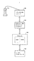
図1に、超音波イメージング装置1のブロック(block)図を示す。超音波イメージング装置1は、発明を実施するための最良の形態の一例である。超音波イメージング装置1の動作によって、データ入力方法に関する発明を実施するための最良の形態の一例が示される。超音波イメージング装置1の構成によって、超音波イメージング装置に関する発明を実施するための最良の形態の一例が示される。
The best mode for carrying out the invention will be described below in detail with reference to the drawings. Note that the present invention is not limited to the best mode for carrying out the invention.
FIG. 1 shows a block diagram of the
図1に示すように、超音波イメージング装置1は、プローブ(probe)110を有する。プローブ110は、トランスミッタ&レシーバ(transmitter & receiver)120に接続されている。トランスミッタ&レシーバ120は、プローブ110を駆動して超音波を送信させるとともに、プローブ110を通じてエコー(echo)信号を受信する。
As shown in FIG. 1, the
トランスミッタ&レシーバ120は、デモジュレータ&フロントエンドコントローラ(demodulator & front-end controller)130の制御の下で、超音波の送受信を周期的に繰り返すとともに、送受信方位の逐次切替えによってイメージング範囲をスキャン(scan)する。以下、超音波送受信の繰り返しの周期をPRT(Pulse Repetition Time)という。
The transmitter &
デモジュレータ&フロントエンドコントローラ130は、トランスミッタ&レシーバ120のエコー受信信号をデモジュレーション(demodulation)して超音波ローデータを生成する。以下、超音波ローデータを単にローデータともいう。
The demodulator &
デモジュレータ&フロントエンドコントローラ130は、例えば、FPGA(Field Programmable Gate Array)やASIC(Application Specific Integrated Circuit)等の半導体集積回路で構成される。
The demodulator & front-
ローデータは、デモジュレータ&フロントエンドコントローラ130からプロセッサ140に入力される。プロセッサ140は、ローデータについて超音波イメージング用の種々のデータ処理を行い、例えば、Bモード画像、CFM(Color Flow Mapping)画像、ドップラ(Doppler)画像、ドップラ音等、所定の画像ないし音響を再構成する。
The raw data is input from the demodulator &
プロセッサ140としては、例えば、DSPコア(Digital Signal Processor core)およびARMコア(Advanced RISC Machine core)を有するシステムLSI(System Large Scale Integrated Circuit)が用いられる。この種のシステムLSIは、SoC(System on a Chip)として市販されている。プロセッサ140は、本発明におけるプロセッサの一例である。
As the
プロセッサ140が再構成した画像や音響は、ユーザーインターフェース(user interface)150を通じて、ユーザー(user)に提示される。ユーザーインターフェース150は、グラフィックディスプレイ(graphic display)等で画像を表示し、スピーカ(speaker)等で音響を奏鳴する。
Images and sounds reconstructed by the
図2に、デモジュレータ&フロントエンドコントローラ130とプロセッサ140の詳細な構成を示す。図2に示すように、デモジュレータ&フロントエンドコントローラ130は、デモジュレータ302とフロントエンドコントローラ304を有する。
FIG. 2 shows detailed configurations of the demodulator & front-
プロセッサ140は、データ処理の中枢として、DSPコア402とARMコア404を有する。プロセッサ140は、また、フロントエンド(front end)として、ビデオプロセッシング・フロントエンド(Video Processing Front End : VPFE)406を有し、バックエンド(back end)として、ビデオプロセッシング・バックエンド(Video Processing Back End : VPBE)408を有する。
The
プロセッサ140は、さらに、ペリフェラル(peripheral)として、エクスターナルメモリ・インターフェース(External Memory Interface : EMIF)410、DDR2(Double Data Rate 2)インターフェース412、UART(Universal Asynchronous Receiver Transmitter)インターフェース414、EMAC(Ethernet(富士ゼロックス株式会社の登録商標) MAC)インターフェース416、SD(SD Memory Card)インターフェース418およびUSB(Universal Serial Bus)インターフェース420を有する。
Further, the
ビデオプロセッシング・フロントエンド406のビデオポート(video port)には、ビデオバス(video bus)342によって、デモジュレータ302が接続される。デモジュレータ302が生成したローデータは、ビデオバス342を通じて、ビデオプロセッシング・フロントエンド406のビデオポートに入力される。デモジュレータ302は、本発明におけるデータ入力手段の一例である。
A
エクスターナルメモリ・インターフェース410には、エクスターナルメモリ・インターフェースバス(External Memory Interface Bus)344によって、デモジュレータ302、フロントエンド・コントローラ304およびフラッシュメモリ(Flash Memory : FLASH)346が接続される。
The
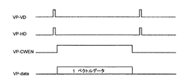
図3に、データ入力のタイムチャート(time chart)を示す。図3に示すように、垂直同期信号VP−VD(Video Port Vertical synchronization)、水平同期信号VP−HD(Video Port Horizontal synchronization)およびライトイネーブル(write enable)信号VP−CWEN(Video Port CCD Controller Write Enable)を伴って、1ベクトルデータ(one vector data)VP−data(Video Port data)が入力される。 FIG. 3 shows a time chart for data input. As shown in FIG. 3, a vertical synchronization signal VP-VD (Video Port Vertical synchronization), a horizontal synchronization signal VP-HD (Video Port Horizontal synchronization), and a write enable signal VP-CWEN (Video Port CCD Controller Write Enable ), One vector data VP-data (Video Port data) is input.
垂直同期信号VP−VD、水平同期信号VP−HDおよびライトイネーブル(write enable)信号VP−CWENは、ビデオプロセッシング・フロントエンド406内のCCDコントローラ(Charge Coupled Device controller)のための同期信号および書き込み制御信号である。
The vertical synchronization signal VP-VD, the horizontal synchronization signal VP-HD, and the write enable signal VP-CWEN are a synchronization signal and write control for the CCD controller (Charge Coupled Device controller) in the video processing
1ベクトルデータVP−dataは、ローデータをパッキング(packing)することにより構成される。ローデータのパッキングは、1PRTごとに行われる。すなわち、ローデータは、1PRT分ずつパッキングされて、それぞれ1ベクトルデータとなる。ローデータのパッキングは、デモジュレータ302において行われる。
One vector data VP-data is configured by packing raw data. Raw data packing is performed for each PRT. That is, the raw data is packed by 1 PRT and becomes 1 vector data. Raw data packing is performed in the
このように、ローデータをベクトルデータにして入力することにより、ビデオプロセッシング・フロントエンド406の高速性を利用した高速なデータ入力を行うことができる。したがって、DMAやPCI等の高速データ伝送システムを使用することなく、データ入力を高速に行うことが可能となる。
Thus, by inputting raw data as vector data, high-speed data input utilizing the high speed of the video processing
また、ビデオプロセッシング・フロントエンド406のビデオポートは、多様なデータサイズ(data size)に適応できるので、例えば、Bモード、CFMモード、ドップラモード等、超音波イメージングのモードの相違によるローデータのサイズの如何に関わらず、高速のデータ入力を行うことができる。
In addition, since the video port of the video processing
1 : 超音波イメージング装置
110 : プローブ
120 : トランスミッタ&レシーバ
130 : デモジュレータ&フロントエンドコントローラ
140 : プロセッサ
150 : ユーザーインターフェース
302 : デモジュレータ
304 : フロントエンドコントローラ
342 : ビデオバス
344 :エクスターナルメモリ・インターフェースバス
402 : DSPコア
404 : ARMコア
406 : ビデオプロセッシング・フロントエンド
410 : エクスターナルメモリ・インターフェース
DESCRIPTION OF SYMBOLS 1: Ultrasound imaging apparatus 110: Probe 120: Transmitter & receiver 130: Demodulator & front end controller 140: Processor 150: User interface 302: Demodulator 304: Front end controller 342: Video bus 344: External memory interface bus 402 : DSP core 404: ARM core 406: Video processing front end 410: External memory interface
Claims (20)
超音波ローデータをプロセッサのビデオプロセッシング・フロントエンドに入力する
ことを特徴とするデータ入力方法。 A method of inputting ultrasonic raw data to a processor,
A data input method comprising inputting ultrasonic raw data to a video processing front end of a processor.
ことを特徴とする請求項1に記載のデータ入力方法。 The data input method according to claim 1, wherein the ultrasonic raw data is input as vector data.
ことを特徴とする請求項2に記載のデータ入力方法。 The data input method according to claim 2, wherein the vector data is configured by packing the ultrasonic raw data.
ことを特徴とする請求項3に記載のデータ入力方法。 4. The data input method according to claim 3, wherein the packing of the ultrasonic raw data is performed every 1 PRT.
ことを特徴とする請求項2に記載のデータ入力方法。 The data input method according to claim 2, wherein the vector data is input together with a synchronization signal.
ことを特徴とする請求項5に記載のデータ入力方法。 6. The data input method according to claim 5, wherein the synchronization signal is input for each vector data.
ことを特徴とする請求項6に記載のデータ入力方法。 The data input method according to claim 6, wherein the synchronization signal includes a vertical synchronization signal and a horizontal synchronization signal.
ことを特徴とする請求項2に記載のデータ入力方法。 The data input method according to claim 2, wherein the vector data is input together with a write enable signal.
ことを特徴とする請求項8に記載のデータ入力方法。 9. The data input method according to claim 8, wherein the write enable signal is input for each vector data.
ことを特徴とする請求項1に記載のデータ入力方法。 The data input method according to claim 1, wherein the ultrasonic raw data has a variable data size.
ビデオプロセッシング・フロントエンドを有するプロセッサと、
前記プロセッサのビデオプロセッシング・フロントエンドに超音波ローデータを入力するデータ入力手段
を具備することを特徴とする超音波イメージング装置。 An ultrasound imaging apparatus that processes ultrasound raw data with a processor,
A processor having a video processing front end;
An ultrasonic imaging apparatus comprising data input means for inputting ultrasonic raw data to a video processing front end of the processor.
ことを特徴とする請求項11に記載の超音波イメージング装置。 The ultrasonic imaging apparatus according to claim 11, wherein the ultrasonic raw data is input as vector data.
ことを特徴とする請求項12に記載の超音波イメージング装置。 The ultrasound imaging apparatus according to claim 12, wherein the vector data is configured by packing the ultrasound raw data.
ことを特徴とする請求項13に記載の超音波イメージング装置。 The ultrasonic imaging apparatus according to claim 13, wherein packing of the ultrasonic raw data is performed every 1 PRT.
ことを特徴とする請求項12に記載の超音波イメージング装置。 The ultrasonic imaging apparatus according to claim 12, wherein the vector data is input together with a synchronization signal.
ことを特徴とする請求項15に記載の超音波イメージング装置。 The ultrasonic imaging apparatus according to claim 15, wherein the synchronization signal is input for each vector data.
ことを特徴とする請求項16に記載の超音波イメージング装置。 The ultrasonic imaging apparatus according to claim 16, wherein the synchronization signal includes a vertical synchronization signal and a horizontal synchronization signal.
ことを特徴とする請求項12に記載の超音波イメージング装置。 The ultrasonic imaging apparatus according to claim 12, wherein the vector data is input together with a write enable signal.
ことを特徴とする請求項18に記載の超音波イメージング装置。 The ultrasonic imaging apparatus according to claim 18, wherein the write enable signal is input for each vector data.
ことを特徴とする請求項11に記載の超音波イメージング装置。 The ultrasonic imaging apparatus according to claim 11, wherein the ultrasonic raw data has a variable data size.
Applications Claiming Priority (2)
| Application Number | Priority Date | Filing Date | Title |
|---|---|---|---|
| CN200810131451.3 | 2008-06-20 | ||
| CNA2008101314513A CN101606848A (en) | 2008-06-20 | 2008-06-20 | Data entry device and supersonic imaging device |
Publications (2)
| Publication Number | Publication Date |
|---|---|
| JP2010000347A true JP2010000347A (en) | 2010-01-07 |
| JP5541882B2 JP5541882B2 (en) | 2014-07-09 |
Family
ID=41431357
Family Applications (1)
| Application Number | Title | Priority Date | Filing Date |
|---|---|---|---|
| JP2009132198A Active JP5541882B2 (en) | 2008-06-20 | 2009-06-01 | Data input method and ultrasonic imaging apparatus |
Country Status (3)
| Country | Link |
|---|---|
| US (1) | US8965073B2 (en) |
| JP (1) | JP5541882B2 (en) |
| CN (1) | CN101606848A (en) |
Families Citing this family (2)
| Publication number | Priority date | Publication date | Assignee | Title |
|---|---|---|---|---|
| CN103033807B (en) * | 2011-09-30 | 2014-12-10 | 中国科学院声学研究所 | Portable ultrasonic imaging system receiving front-end device |
| CN109459500A (en) * | 2018-10-31 | 2019-03-12 | 西北工业大学深圳研究院 | The online high speed acquisition processing system of acoustic emission signal |
Citations (5)
| Publication number | Priority date | Publication date | Assignee | Title |
|---|---|---|---|---|
| JP2004065370A (en) * | 2002-08-02 | 2004-03-04 | Hitachi Medical Corp | Ultrasonograph equipment, method for creating ultrasonographic information, and ultrasonographic system |
| JP2004351083A (en) * | 2003-05-30 | 2004-12-16 | Aloka Co Ltd | Ultrasonoi diagnostic system, and received data processing method |
| JP2005177494A (en) * | 2003-12-19 | 2005-07-07 | General Electric Co <Ge> | Method and apparatus for flow parameter imaging |
| JP2007244580A (en) * | 2006-03-15 | 2007-09-27 | Aloka Co Ltd | Wireless ultrasonic diagnostic apparatus |
| JP2008114065A (en) * | 2006-11-06 | 2008-05-22 | General Electric Co <Ge> | Hand-held type ultrasonic system equipped with single integrated circuit back end |
Family Cites Families (30)
| Publication number | Priority date | Publication date | Assignee | Title |
|---|---|---|---|---|
| US4893286A (en) * | 1987-11-04 | 1990-01-09 | Standard Oil Company | System and method for preprocessing and transmitting echo waveform information |
| US5453575A (en) * | 1993-02-01 | 1995-09-26 | Endosonics Corporation | Apparatus and method for detecting blood flow in intravascular ultrasonic imaging |
| US5483963A (en) | 1994-07-22 | 1996-01-16 | Loral Infrared & Imaging Systems, Inc. | Two dimensional transducer integrated circuit |
| TW282540B (en) * | 1994-12-20 | 1996-08-01 | Sanyo Electric Machinery Co Ltd | |
| US6248073B1 (en) * | 1995-06-29 | 2001-06-19 | Teratech Corporation | Ultrasound scan conversion with spatial dithering |
| US5628321A (en) * | 1995-12-18 | 1997-05-13 | Diasonics Ultrasound, Inc. | Processing velocity information in an ultrasonic system |
| US5709209A (en) * | 1996-03-29 | 1998-01-20 | Siemens Medical Systems, Inc. | Ultrasound signal processing system |
| US5722412A (en) * | 1996-06-28 | 1998-03-03 | Advanced Technology Laboratories, Inc. | Hand held ultrasonic diagnostic instrument |
| US5782769A (en) * | 1996-06-28 | 1998-07-21 | Advanced Technology Laboratories, Inc. | Ultrasonic diagnostic image flash suppression technique |
| US6203498B1 (en) * | 1996-06-28 | 2001-03-20 | Sonosite, Inc. | Ultrasonic imaging device with integral display |
| CA2214919A1 (en) * | 1996-09-24 | 1998-03-24 | Kenneth Lee Hauser | Benzothiophene compounds, intermediates, processes, compositions, and methods |
| US5926187A (en) * | 1996-10-18 | 1999-07-20 | Samsung Electronics Co., Ltd. | Video interface and overlay system and process |
| US6904110B2 (en) * | 1997-07-31 | 2005-06-07 | Francois Trans | Channel equalization system and method |
| US6570579B1 (en) * | 1998-11-09 | 2003-05-27 | Broadcom Corporation | Graphics display system |
| US6547730B1 (en) * | 1998-12-31 | 2003-04-15 | U-Systems, Inc. | Ultrasound information processing system |
| US6375618B1 (en) * | 2000-01-31 | 2002-04-23 | General Electric Company | Enhanced tissue-generated harmonic imaging using coded excitation |
| JP3828744B2 (en) | 2000-12-18 | 2006-10-04 | ジーイー・メディカル・システムズ・グローバル・テクノロジー・カンパニー・エルエルシー | Ultrasound imaging device |
| US6607489B2 (en) * | 2001-04-05 | 2003-08-19 | General Electric Company | Focus correction for ultrasound imaging through mammography compression plate |
| JP4248933B2 (en) | 2003-05-23 | 2009-04-02 | オリンパス株式会社 | Ultrasonic diagnostic equipment |
| JP2005117494A (en) | 2003-10-09 | 2005-04-28 | Konica Minolta Photo Imaging Inc | Imaging apparatus |
| US6926369B2 (en) * | 2003-12-05 | 2005-08-09 | Mccaster, Iii Tommie L. | Wheel assembly |
| US20050228281A1 (en) * | 2004-03-31 | 2005-10-13 | Nefos Thomas P | Handheld diagnostic ultrasound system with head mounted display |
| US7105986B2 (en) * | 2004-08-27 | 2006-09-12 | General Electric Company | Ultrasound transducer with enhanced thermal conductivity |
| US8211019B2 (en) * | 2005-01-21 | 2012-07-03 | Chikayoshi Sumi | Clinical apparatuses |
| US8221324B2 (en) * | 2006-05-05 | 2012-07-17 | Worcester Polytechnic Institute | Reconfigurable wireless ultrasound diagnostic system |
| US8475375B2 (en) * | 2006-12-15 | 2013-07-02 | General Electric Company | System and method for actively cooling an ultrasound probe |
| US7681012B2 (en) * | 2007-01-30 | 2010-03-16 | Texas Instruments Incorporated | Method, system and device for handling a memory management fault in a multiple processor device |
| US8009904B2 (en) * | 2007-07-13 | 2011-08-30 | Siemens Medical Solutions Usa, Inc. | Medical diagnostic ultrasound gray scale mapping for dynamic range on a display |
| US20100286519A1 (en) * | 2009-05-11 | 2010-11-11 | General Electric Company | Ultrasound system and method to automatically identify and treat adipose tissue |
| US20100286518A1 (en) * | 2009-05-11 | 2010-11-11 | General Electric Company | Ultrasound system and method to deliver therapy based on user defined treatment spaces |
-
2008
- 2008-06-20 CN CNA2008101314513A patent/CN101606848A/en active Pending
-
2009
- 2009-06-01 JP JP2009132198A patent/JP5541882B2/en active Active
- 2009-06-18 US US12/487,357 patent/US8965073B2/en active Active
Patent Citations (5)
| Publication number | Priority date | Publication date | Assignee | Title |
|---|---|---|---|---|
| JP2004065370A (en) * | 2002-08-02 | 2004-03-04 | Hitachi Medical Corp | Ultrasonograph equipment, method for creating ultrasonographic information, and ultrasonographic system |
| JP2004351083A (en) * | 2003-05-30 | 2004-12-16 | Aloka Co Ltd | Ultrasonoi diagnostic system, and received data processing method |
| JP2005177494A (en) * | 2003-12-19 | 2005-07-07 | General Electric Co <Ge> | Method and apparatus for flow parameter imaging |
| JP2007244580A (en) * | 2006-03-15 | 2007-09-27 | Aloka Co Ltd | Wireless ultrasonic diagnostic apparatus |
| JP2008114065A (en) * | 2006-11-06 | 2008-05-22 | General Electric Co <Ge> | Hand-held type ultrasonic system equipped with single integrated circuit back end |
Non-Patent Citations (6)
| Title |
|---|
| CSND199801162016; 太田博之他: '移動体通信テクノロジの基礎第2回' Interface 第24巻 第7号, 19980701, 第207-212頁, CQ出版株式会社 * |
| CSND200100174002; 鏡慎吾他: '超並列ビジョンチップ開発は今・・・' エレクトロニクス 第46巻 、第3号, 20010301, 第6-9頁, 株式会社オーム社 * |
| CSND200100469006; 粕谷英夫: 'カーエレクトロニクスとEMC' エレクトロニクス 第44巻、第10号, 19991001, 第47-53頁, 株式会社オーム社 * |
| JPN6013056976; 太田博之他: '移動体通信テクノロジの基礎第2回' Interface 第24巻 第7号, 19980701, 第207-212頁, CQ出版株式会社 * |
| JPN6013056977; 鏡慎吾他: '超並列ビジョンチップ開発は今・・・' エレクトロニクス 第46巻 、第3号, 20010301, 第6-9頁, 株式会社オーム社 * |
| JPN6013056978; 粕谷英夫: 'カーエレクトロニクスとEMC' エレクトロニクス 第44巻、第10号, 19991001, 第47-53頁, 株式会社オーム社 * |
Also Published As
| Publication number | Publication date |
|---|---|
| US20090316974A1 (en) | 2009-12-24 |
| JP5541882B2 (en) | 2014-07-09 |
| US8965073B2 (en) | 2015-02-24 |
| CN101606848A (en) | 2009-12-23 |
Similar Documents
| Publication | Publication Date | Title |
|---|---|---|
| TWI378255B (en) | Ultrasonic image processing system and ultrasonic image processing method thereof | |
| CN103284757A (en) | Method and apparatus for performing ultrasound imaging | |
| WO2017013511A1 (en) | Ultrasound system with processor dongle | |
| US10420536B2 (en) | Software-based ultrasound imaging system | |
| BR112015021282B1 (en) | Ultrasound image capture device, ultrasound imaging system, ultrasound image capture kit, and method for specifying an operating state for an ultrasound image capture | |
| TW201621313A (en) | Parameter loader for ultrasound probe and related apparatus and methods | |
| JP2013121493A (en) | Ultrasonic diagnostic system and data processing program for the same | |
| Sikdar et al. | A single mediaprocessor-based programmable ultrasound system | |
| JP5541882B2 (en) | Data input method and ultrasonic imaging apparatus | |
| US20200214668A1 (en) | Distributed portable ultrasound system | |
| JP2014188149A5 (en) | ||
| TWI511478B (en) | Ultrasound data acquisition system, and method and ultrasound receiving device | |
| CN202096223U (en) | Type-B ultrasound probe | |
| JP3967149B2 (en) | Ultrasonic diagnostic equipment | |
| Kim et al. | A smart-phone based portable ultrasound imaging system for point-of-care applications | |
| JP7202905B2 (en) | Ultrasound diagnostic equipment and ultrasound probe | |
| Levesque et al. | Novel low-power ultrasound digital preprocessing architecture for wireless display | |
| CN201782770U (en) | Novel B ultrasonic probe and portable B ultrasonic equipment | |
| Xu | AFE5832LP and AFE5832 Ultrasound Analog Front End for Ultra-Portable Applications | |
| JP3251099B2 (en) | Ultrasound diagnostic equipment | |
| TW201001365A (en) | Display applied to mobile communication device | |
| Dezotti et al. | FPGA-based reception board of 64-channels ultrasound research platform | |
| WO2015080315A1 (en) | Ultrasonic diagnostic apparatus and method | |
| Lee et al. | Software-based hand-held ultrasound color Doppler imaging system | |
| JP2014033821A (en) | Ultrasonic diagnostic apparatus |
Legal Events
| Date | Code | Title | Description |
|---|---|---|---|
| RD04 | Notification of resignation of power of attorney |
Free format text: JAPANESE INTERMEDIATE CODE: A7424 Effective date: 20111114 |
|
| A625 | Written request for application examination (by other person) |
Free format text: JAPANESE INTERMEDIATE CODE: A625 Effective date: 20120413 |
|
| A131 | Notification of reasons for refusal |
Free format text: JAPANESE INTERMEDIATE CODE: A131 Effective date: 20130611 |
|
| A977 | Report on retrieval |
Free format text: JAPANESE INTERMEDIATE CODE: A971007 Effective date: 20130612 |
|
| RD02 | Notification of acceptance of power of attorney |
Free format text: JAPANESE INTERMEDIATE CODE: A7422 Effective date: 20130627 |
|
| RD04 | Notification of resignation of power of attorney |
Free format text: JAPANESE INTERMEDIATE CODE: A7424 Effective date: 20130627 |
|
| A521 | Request for written amendment filed |
Free format text: JAPANESE INTERMEDIATE CODE: A523 Effective date: 20130909 |
|
| A02 | Decision of refusal |
Free format text: JAPANESE INTERMEDIATE CODE: A02 Effective date: 20131119 |
|
| A521 | Request for written amendment filed |
Free format text: JAPANESE INTERMEDIATE CODE: A523 Effective date: 20140224 |
|
| A911 | Transfer to examiner for re-examination before appeal (zenchi) |
Free format text: JAPANESE INTERMEDIATE CODE: A911 Effective date: 20140303 |
|
| TRDD | Decision of grant or rejection written | ||
| A01 | Written decision to grant a patent or to grant a registration (utility model) |
Free format text: JAPANESE INTERMEDIATE CODE: A01 Effective date: 20140408 |
|
| A61 | First payment of annual fees (during grant procedure) |
Free format text: JAPANESE INTERMEDIATE CODE: A61 Effective date: 20140502 |
|
| R150 | Certificate of patent or registration of utility model |
Ref document number: 5541882 Country of ref document: JP Free format text: JAPANESE INTERMEDIATE CODE: R150 |
|
| R250 | Receipt of annual fees |
Free format text: JAPANESE INTERMEDIATE CODE: R250 |
|
| R250 | Receipt of annual fees |
Free format text: JAPANESE INTERMEDIATE CODE: R250 |
|
| R250 | Receipt of annual fees |
Free format text: JAPANESE INTERMEDIATE CODE: R250 |
|
| R250 | Receipt of annual fees |
Free format text: JAPANESE INTERMEDIATE CODE: R250 |
|
| R250 | Receipt of annual fees |
Free format text: JAPANESE INTERMEDIATE CODE: R250 |
|
| R250 | Receipt of annual fees |
Free format text: JAPANESE INTERMEDIATE CODE: R250 |
|
| R250 | Receipt of annual fees |
Free format text: JAPANESE INTERMEDIATE CODE: R250 |
|
| R250 | Receipt of annual fees |
Free format text: JAPANESE INTERMEDIATE CODE: R250 |