JP2010000340A - Image processor, image processing method and image processing program - Google Patents
Image processor, image processing method and image processing program Download PDFInfo
- Publication number
- JP2010000340A JP2010000340A JP2009080121A JP2009080121A JP2010000340A JP 2010000340 A JP2010000340 A JP 2010000340A JP 2009080121 A JP2009080121 A JP 2009080121A JP 2009080121 A JP2009080121 A JP 2009080121A JP 2010000340 A JP2010000340 A JP 2010000340A
- Authority
- JP
- Japan
- Prior art keywords
- dimensional
- image
- information
- blood flow
- generated
- Prior art date
- Legal status (The legal status is an assumption and is not a legal conclusion. Google has not performed a legal analysis and makes no representation as to the accuracy of the status listed.)
- Granted
Links
Images


Classifications
-
- A—HUMAN NECESSITIES
- A61—MEDICAL OR VETERINARY SCIENCE; HYGIENE
- A61B—DIAGNOSIS; SURGERY; IDENTIFICATION
- A61B8/00—Diagnosis using ultrasonic, sonic or infrasonic waves
- A61B8/06—Measuring blood flow
-
- A—HUMAN NECESSITIES
- A61—MEDICAL OR VETERINARY SCIENCE; HYGIENE
- A61B—DIAGNOSIS; SURGERY; IDENTIFICATION
- A61B8/00—Diagnosis using ultrasonic, sonic or infrasonic waves
- A61B8/13—Tomography
-
- A—HUMAN NECESSITIES
- A61—MEDICAL OR VETERINARY SCIENCE; HYGIENE
- A61B—DIAGNOSIS; SURGERY; IDENTIFICATION
- A61B8/00—Diagnosis using ultrasonic, sonic or infrasonic waves
- A61B8/48—Diagnostic techniques
- A61B8/483—Diagnostic techniques involving the acquisition of a 3D volume of data
-
- G—PHYSICS
- G06—COMPUTING; CALCULATING OR COUNTING
- G06T—IMAGE DATA PROCESSING OR GENERATION, IN GENERAL
- G06T15/00—3D [Three Dimensional] image rendering
- G06T15/08—Volume rendering
-
- G—PHYSICS
- G06—COMPUTING; CALCULATING OR COUNTING
- G06T—IMAGE DATA PROCESSING OR GENERATION, IN GENERAL
- G06T19/00—Manipulating 3D models or images for computer graphics
-
- G—PHYSICS
- G06—COMPUTING; CALCULATING OR COUNTING
- G06T—IMAGE DATA PROCESSING OR GENERATION, IN GENERAL
- G06T2210/00—Indexing scheme for image generation or computer graphics
- G06T2210/24—Fluid dynamics
-
- G—PHYSICS
- G06—COMPUTING; CALCULATING OR COUNTING
- G06T—IMAGE DATA PROCESSING OR GENERATION, IN GENERAL
- G06T2210/00—Indexing scheme for image generation or computer graphics
- G06T2210/41—Medical
Abstract
Description
この発明は、画像処理装置、画像処理方法および画像処理プログラムに関する。 The present invention relates to an image processing apparatus, an image processing method, and an image processing program.
従来より、超音波診断装置は、X線診断装置やX線コンピュータ断層撮影装置などの他の医用画像診断装置に比べ、簡便な操作性、被爆のおそれがない非侵襲性などの利点を備えた装置として、今日の医療において、心臓、肝臓、腎臓、乳腺など、様々な生体組織の検査や診断に利用されている。 Conventionally, an ultrasonic diagnostic apparatus has advantages such as simple operability and non-invasiveness that does not cause exposure, compared to other medical image diagnostic apparatuses such as an X-ray diagnostic apparatus and an X-ray computed tomography apparatus. As a device, in today's medical care, it is used for examination and diagnosis of various living tissues such as heart, liver, kidney and mammary gland.
超音波診断装置は、超音波プローブから超音波を送信し、被検体の内部組織から反射された超音波を受信することによって、被検体内の組織構造の断層像(Bモード像)をリアルタイムに生成する。さらに、超音波診断装置は、超音波のドプラ効果を利用して被検体内の血流が存在する範囲とともに、血流の速度、分散(血流の乱れ)およびパワー(血流の散乱強度)などの血流情報を画像(ドプラ像)としてリアルタイムに生成する。 The ultrasonic diagnostic apparatus transmits an ultrasonic wave from an ultrasonic probe and receives an ultrasonic wave reflected from the internal tissue of the subject, thereby obtaining a tomographic image (B-mode image) of the tissue structure in the subject in real time. Generate. Furthermore, the ultrasonic diagnostic apparatus utilizes the Doppler effect of ultrasonic waves, as well as the range of blood flow in the subject, blood flow velocity, dispersion (perturbation of blood flow), and power (blood flow scattering intensity). Blood flow information such as is generated in real time as an image (Doppler image).
また、近年、2次元アレイ振動子超音波プローブを用いて被検体内を3次元でスキャンすることにより、リアルタイムで3次元の超音波画像を生成する超音波診断装置が実用化されている。3次元スキャンを行う超音波診断装置は、例えば、経時的に拍動する心臓の3次元的な組織構造のBモード画像をリアルタイムで収集して表示することが可能である。 In recent years, an ultrasonic diagnostic apparatus that generates a three-dimensional ultrasonic image in real time by scanning the inside of a subject in three dimensions using a two-dimensional array transducer ultrasonic probe has been put into practical use. An ultrasonic diagnostic apparatus that performs a three-dimensional scan can collect and display a B-mode image of a three-dimensional tissue structure of a heart that beats with time, for example, in real time.
3次元のBモード画像を表示する際には、ボリュームレンダリングの手法が用いられる。例えば、心臓の組織構造は、Bモード像で高輝度に表現される心臓壁や弁と、その内部のほとんどが黒で表現される心腔とから成り立っている。このため、心臓の半分を表示対象領域としてボリュームレンダリングすることによって、心腔内から心壁や心臓弁を見た立体像を表示することができる。心臓の半分をボリュームレンダリングした立体像を参照することにより、医師は、心臓弁や心壁の疾患や心臓弁や心壁先天性異常の診断を効率よく行なうことができる。 When displaying a three-dimensional B-mode image, a volume rendering method is used. For example, the tissue structure of the heart is composed of a heart wall and a valve that are expressed with high brightness in a B-mode image, and a heart chamber that is mostly expressed in black. Therefore, a volumetric rendering with half of the heart as a display target region can display a three-dimensional image of the heart wall and heart valve viewed from within the heart chamber. By referring to a three-dimensional image in which half of the heart is volume-rendered, a doctor can efficiently diagnose a heart valve or heart wall disease or a heart valve or heart wall congenital abnormality.
ここで、3次元スキャンを行う超音波診断装置は、組織構造の3次元情報と同時に、ドプラ効果を利用して血流の3次元情報も同時に収集することができ、3次元のドプラ像に対してボリュームレンダリングを行なうことにより、3次元の血流分布を表示することが可能となっている。 Here, an ultrasonic diagnostic apparatus that performs a three-dimensional scan can simultaneously collect three-dimensional information of blood flow using the Doppler effect simultaneously with the three-dimensional information of the tissue structure. By performing volume rendering, it is possible to display a three-dimensional blood flow distribution.
例えば、3次元のドプラ像に対してボリュームレンダリングを行なう際に、血流情報における血流速度の分散を利用することで、血液の乱流を3次元的に強調した描出を行なうことができ(例えば、特許文献1参照)、これにより、心臓弁や心壁の異常により生じる乱流性血流をわかりやすく表示することができる。 For example, when performing volume rendering on a three-dimensional Doppler image, it is possible to perform a three-dimensionally enhanced depiction of blood turbulence by using the distribution of blood flow velocity in blood flow information ( For example, refer to Patent Document 1), whereby turbulent blood flow caused by an abnormality in a heart valve or a heart wall can be displayed in an easy-to-understand manner.
ところで、上記した従来の技術は、診断に適した形式で、血流を3次元的に表示することができないという課題があった。 By the way, the above-described conventional technique has a problem that blood flow cannot be three-dimensionally displayed in a format suitable for diagnosis.
例えば、心臓において、血液は心腔内に充満しており、また、血流の速度は連続的に変化するために、血流が存在する領域には、明瞭な境界がない。このため、3次元のドプラ像に対してボリュームレンダリングを行った場合、血流を立体的に表示することができない。 For example, in the heart, blood fills the heart chamber and the speed of blood flow changes continuously, so there is no clear boundary in the region where blood flow exists. For this reason, when volume rendering is performed on a three-dimensional Doppler image, the blood flow cannot be displayed stereoscopically.
また、医師が効率よく診断を行なうためには、血流情報と同時に組織構造の情報が必要となるが、ボリュームレンダリングを行なった3次元のBモード像を、ボリュームレンダリングを行なった3次元のドプラ像と重畳して表示した場合、血流の背面にある組織構造が隠れてしまう。このため、血流情報とともに、組織構造の情報をわかりやすく表示できない。 In addition, in order for a doctor to make an efficient diagnosis, blood flow information and tissue structure information are required, but a three-dimensional B-mode image subjected to volume rendering is converted to a three-dimensional Doppler subjected to volume rendering. When displayed superimposed on the image, the tissue structure behind the bloodstream is hidden. For this reason, the information on the tissue structure cannot be easily displayed together with the blood flow information.
このように、上記した従来の技術は、心臓弁や心壁の異常により生じる乱流性血流をわかりやすく表示することが可能ではあるが、血流の3次元情報を、組織構造の3次元情報とともに、診断に適した形式で表示することができなかった。 As described above, the above-described conventional technology can easily display the turbulent blood flow caused by the abnormality of the heart valve or the heart wall. Along with the information, it could not be displayed in a format suitable for diagnosis.
そこで、この発明は、上述した従来技術の課題を解決するためになされたものであり、診断に適した形式で、血流を3次元的に表示することが可能になる画像処理装置、画像処理方法および画像処理プログラムを提供することを目的とする。 Accordingly, the present invention has been made to solve the above-described problems of the prior art, and an image processing apparatus and image processing that can display blood flow three-dimensionally in a format suitable for diagnosis It is an object to provide a method and an image processing program.
上述した課題を解決し、目的を達成するため、請求項1記載の本発明は、被検体内に対して送信した超音波の反射波に基づいて生成された当該被検体内にある組織の3次元組織構造情報および当該被検体内を移動する流体の3次元流体情報を取得し、前記3次元流体情報において前記流体が存在する範囲に、複数の粒子を3次元空間に離散して配置することにより、当該3次元流体情報を変換した3次元粒子情報を生成し、生成した前記3次元粒子情報と前記3次元組織構造情報とに基づいた合成画像を生成する画像生成部と、前記画像生成部によって生成された前記合成画像を、所定の表示部にて表示するように制御する表示制御部と、を備えたことを特徴とする。
In order to solve the above-described problems and achieve the object, the present invention according to
また、請求項11記載の本発明は、被検体内に対して送信した超音波の反射波に基づいて生成された当該被検体内にある組織の3次元組織構造情報および当該被検体内を移動する流体の3次元流体情報を取得し、前記3次元流体情報において前記流体が存在する範囲に、複数の粒子を3次元空間に離散して配置することにより、当該3次元流体情報を変換した3次元粒子情報を生成し、生成した前記3次元粒子情報と前記3次元組織構造情報とに基づいた合成画像を生成する画像生成ステップと、前記画像生成ステップによって生成された前記合成画像を、所定の表示部にて表示するように制御する表示制御ステップと、を含んだことを特徴とする。
According to the eleventh aspect of the present invention, the three-dimensional tissue structure information of the tissue in the subject generated based on the reflected wave of the ultrasonic wave transmitted to the subject and the movement in the
また、請求項12記載の本発明は、被検体内に対して送信した超音波の反射波に基づいて生成された当該被検体内にある組織の3次元組織構造情報および当該被検体内を移動する流体の3次元流体情報を取得し、前記3次元流体情報において前記流体が存在する範囲に、複数の粒子を3次元空間に離散して配置することにより、当該3次元流体情報を変換した3次元粒子情報を生成し、生成した前記3次元粒子情報と前記3次元組織構造情報とに基づいた合成画像を生成する画像生成手順と、前記画像生成手順によって生成された前記合成画像を、所定の表示部にて表示するように制御する表示制御手順と、をコンピュータに実行させることを特徴とする。 According to the present invention, the three-dimensional tissue structure information of the tissue in the subject generated based on the reflected wave of the ultrasonic wave transmitted to the subject and the movement in the subject. 3 is obtained by converting the three-dimensional fluid information by acquiring a plurality of particles in a three-dimensional space within a range in which the fluid exists in the three-dimensional fluid information. An image generation procedure for generating three-dimensional particle information, generating a composite image based on the generated three-dimensional particle information and the three-dimensional tissue structure information, and the composite image generated by the image generation procedure And a display control procedure for controlling the display to display on the display unit.
請求項1、11または12記載の本発明によれば、最前面の血流によって、背面にある血流や組織構造が隠れてしまうことを回避することができ、診断に適した形式で、血流を3次元的に表示することが可能になる。
According to the present invention of
以下に添付図面を参照して、この発明に係る画像処理装置、画像処理方法および画像処理プログラムの好適な実施例を詳細に説明する。 Exemplary embodiments of an image processing apparatus, an image processing method, and an image processing program according to the present invention are explained in detail below with reference to the accompanying drawings.
まず、実施例1における画像処理装置に接続される超音波診断装置の構成について説明する。図1は、実施例1における画像処理装置に接続される超音波診断装置の構成を説明するための図である。 First, the configuration of the ultrasonic diagnostic apparatus connected to the image processing apparatus according to the first embodiment will be described. FIG. 1 is a diagram for explaining a configuration of an ultrasonic diagnostic apparatus connected to the image processing apparatus according to the first embodiment.
図1に示すように、実施例1における画像処理装置に接続される超音波診断装置20は、超音波プローブ21と、送信部22と、受信部23と、Bモード処理部24と、カラードプラ処理部25と、制御部26とを備える。
As shown in FIG. 1, the ultrasonic
超音波プローブ21は、マトリックス(格子)状に配置された超音波振動子を内蔵する2次元アレイ振動子超音波プローブであり、超音波振動子が発生した超音波を被検体内に送信し、被検体の内部組織からの反射波を、超音波振動子にて受信することにより、被検体内を3次元で走査する。
The
送信部22は、超音波プローブ21と接続され、後述する制御部26の制御にしたがって、所定の遅延時間ごとに高電圧パルスを発生し、発生した高電圧パルスを超音波プローブ21が内蔵する超音波振動子に順次印加する。これにより、超音波プローブ21は、超音波を発生する。
The
受信部23は、超音波プローブ21と接続され、超音波プローブ21が受信した反射波の受信信号が入力されると、ゲイン補正処理およびA/D変換処理を行ない、受信データを生成する。
The
Bモード処理部24は、受信部23が受信して生成した受信データに基づいて、被検体内にある組織の構造を3次元のBモード画像で表現するために用いられる3次元組織データの生成処理を行なう。なお、3次元組織データは、特許請求の範囲に記載の「3次元組織構造情報」に対応する。
The B-
カラードプラ処理部25は、受信部23が受信して生成した受信データと超音波のドプラ効果とを用いて、被検体内を移動する血流の存在する範囲とともに、血流の速度値、分散値(血流の乱れ)およびパワー(血流の散乱強度)などの血流情報を3次元のカラードプラ画像で表現するために用いられる3次元血流データの生成処理を行なう。なお、血流は、特許請求の範囲に記載の「流体」に対応し、3次元血流データは、同じく「3次元流体情報」に対応する。
The color
制御部26は、超音波診断装置20の操作者から、図示しない入力部を介して受け付けた設定条件に基づいて、上述した送信部22、受信部23、Bモード処理部24およびカラードプラ処理部25を制御する。具体的には、送信部22が発生する高電圧パルスの遅延時間や、受信部23とBモード処理部24との間での受信データの送受信のタイミングや、受信部23とカラードプラ処理部25との間での受信データの送受信のタイミングなどの設定条件に基づいて、送信部22、受信部23、Bモード処理部24およびカラードプラ処理部25を制御する。
Based on the setting conditions received from the operator of the ultrasonic
そして、画像処理装置10は、Bモード処理部24によって生成された3次元組織データおよびカラードプラ処理部25によって生成された3次元血流データを用いて生成した画像を表示するが、診断に適した形式で、血流を3次元的に表示することが可能になることを主たる特徴とする。
The
この主たる特徴について図2〜6を用いて説明する。図2は、実施例1における画像処理装置の構成を説明するための図であり、図3は、組織画像生成部を説明するための図であり、図4は、血流データ変換部を説明するための図であり、図5は、血流画像生成部を説明するための図であり、図6は、実施例1における合成画像生成部を説明するための図である。 This main feature will be described with reference to FIGS. 2 is a diagram for explaining the configuration of the image processing apparatus according to the first embodiment, FIG. 3 is a diagram for explaining a tissue image generation unit, and FIG. 4 is a diagram explaining a blood flow data conversion unit. FIG. 5 is a diagram for explaining the blood flow image generation unit, and FIG. 6 is a diagram for explaining the composite image generation unit in the first embodiment.
図2に示すように、実施例1における画像処理装置10は、超音波診断装置20に接続され、入力部11と、出力部12と、3次元データ記憶部13と、画像生成部14と、合成画像記憶部15と、表示制御部16とを備える。
As illustrated in FIG. 2, the
入力部11は、各種情報を入力し、マウスやキーボードなどを備え、特に本発明に密接に関連するものとしては、画像処理装置10の操作者(例えば、超音波診断装置20によって生成されたデータに基づく画像を読影して診断を行なう医師)からの画像表示要求を受け付けて入力する。また、入力部11は、画像処理装置10の操作者からの表示対象領域設定要求も受け付けて入力する。
The
出力部12は、各種情報を出力し、モニタやスピーカなどを備え、特に本発明に密接に関連するものとしては、後述する画像生成部14によって生成された合成画像を、後述する表示制御部16の制御に基づいて、モニタに表示する。
The
3次元データ記憶部13は、超音波診断装置20によって生成された3次元組織データおよび3次元血流データを記憶する。
The three-dimensional
画像生成部14は、入力部11を介して、画像処理装置10の操作者からの画像表示要求および表示対象領域設定要求を受け付けた場合に、3次元データ記憶部13が記憶する3次元組織データおよび3次元血流データに基づいた合成画像を生成し、図2に示すように、組織画像生成部14aと、血流データ変換部14bと、血流画像生成部14cと、合成画像生成部14dとを備える。
The image generation unit 14 receives the image display request and the display target area setting request from the operator of the
組織画像生成部14aは、3次元データ記憶部13が記憶する3次元組織データから、被検体内にある組織の構造を3次元で表現するBモード画像としての組織画像を生成する。具体的には、組織画像生成部14aは、極座標系で表現される3次元組織データを直交座標系に変換し、直交座標系に変換した3次元組織データにおいて、表示対象領域設定要求に対応する領域をボリュームレンダリングすることにより、組織画像を生成する。
The tissue
また、組織画像生成部14aは、組織画像を生成するとともに、生成した組織画像を構成する画素それぞれの3次元組織データにおける3次元空間での位置情報を取得する。具体的には、組織画像生成部14aは、生成した組織画像における各画素の深度を表す深度値を取得し、取得した各画素の深度値を、生成した組織画像に格納する。
In addition, the tissue
例えば、組織画像生成部14aは、図3に示すように、被検体の心臓からの反射波に基づいて生成された3次元組織データを直交座標系に変換し、直交座標系に変換した3次元組織データにおいて、心臓の半分に対応する領域をボリュームレンダリングすることによって、心腔内から心壁や心臓弁を見た組織画像を生成し、生成した組織画像に各画素の深度値を格納する。
For example, as shown in FIG. 3, the tissue
図2に戻って、血流データ変換部14bは、3次元データ記憶部13が記憶する3次元血流データにおいて血流が存在する範囲に、複数の粒子を3次元空間に離散して配置することにより、3次元血流データを変換した3次元粒子データを生成する。なお、3次元粒子データは、特許請求の範囲に記載の「3次元粒子情報」に対応する。
Returning to FIG. 2, the blood flow
例えば、血流データ変換部14bは、図4の(A)の左側に示すように、3次元血流データにおいて血流が存在する範囲を抽出する。そして、血流データ変換部14bは、図4の(A)の右側に示すように、3次元血流データを予め設定されたサイズにて立方体に分割し、血流が存在する立方体を抽出する。
For example, the blood flow
そして、血流データ変換部14bは、抽出した立方体に、粒子を配置することにより、3次元流体情報を変換した3次元粒子情報を生成する。例えば、血流データ変換部14bは、図4の(B)に示すように、「血流あり」として抽出された立方体の集合において、中心に配置される立方体に、当該立方体のサイズを縮小した(例えば、50%に縮小した)立方体を配置することにより、3次元流体情報を変換した3次元粒子情報を生成する。
Then, the blood flow
図2に戻って、血流画像生成部14cは、血流データ変換部14bによって生成された3次元粒子データを用いて、被検体内の血流情報を、3次元空間に離散して配置した複数の粒子にて表現する血流画像を生成する。具体的には、血流画像生成部14cは、3次元粒子データにおける粒子をポリゴンモデルにて表現したうえで、極座標系で表現される3次元粒子データを直交座標系に変換する。そして、血流画像生成部14cは、直交座標系に変換した3次元粒子データにおいて、表示対象領域設定要求に対応する領域の投影画像を生成することにより、血流画像を生成する。
Returning to FIG. 2, the blood flow
また、血流画像生成部14cは、血流画像を生成するとともに、生成した血流画像に含まれる粒子それぞれの3次元粒子データにおける3次元空間での位置情報を取得する。具体的には、血流画像生成部14cは、生成した血流画像における各粒子の深度を表す深度値を取得し、取得した各粒子の深度値を、生成した血流画像に格納する。
In addition, the blood flow
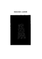
例えば、血流画像生成部14cは、図5に示すように、直交座標系に変換した3次元粒子データにおいて、心臓の半分に対応する領域から投影画像を生成することによって、心腔内から見た血流画像を生成し、生成した血流画像に、各粒子の深度値を格納する。
For example, as shown in FIG. 5, the blood flow
図2に戻って、合成画像生成部14dは、組織画像生成部14aによって生成された組織画像と、血流画像生成部14cによって生成された血流画像とを合成した合成画像を生成する。その際、合成画像生成部14dは、組織画像に含まれる各画素の深度値と、血流画像に含まれる各粒子の深度値とに基づいて、粒子と組織とを描出する順位を調整したうえで合成画像を生成する。
Returning to FIG. 2, the composite
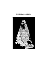
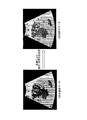
すなわち、合成画像生成部14dは、各画素の深度値と各粒子の深度値とから、組織構造と粒子で表現された血流との深さ方向の重なりを判定し、手前にある組織構造または粒子を優先させて描出するように調整したうえで、合成画像を生成する。例えば、合成画像生成部14dは、図6に示すように、被検体の心臓を心腔内から見た組織構造とともに、血流が粒子で表現された合成画像を、深度値に基づいて生成する。
That is, the composite
そして、合成画像生成部14dは、生成した合成画像を合成画像記憶部15に格納する。
Then, the composite
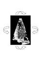
表示制御部16は、合成画像記憶部15が記憶する合成画像を読み込んで、読み込んだ合成画像を出力部12が備えるモニタにて表示するように制御する。また、表示制御部16は、入力部11を介して受け付けた合成画像の回転表示要求に基づいて、図6に示すように、読み込んだ画像を回転表示するように制御する。
The
このように、血流を粒子として表現した血流画像と組織画像とから合成した合成画像を参照することにより、画像処理装置10の操作者(例えば、超音波診断装置20によって撮影された画像を読影して診断を行なう医師)は、最前面にある血流によって隠れてしまう背面の血流分布や組織構造を観察することができる。
In this way, by referring to the composite image synthesized from the blood flow image expressing the blood flow as particles and the tissue image, the operator of the image processing apparatus 10 (for example, the image photographed by the ultrasonic
なお、本実施例では、合成画像生成部14dが、組織画像に含まれる各画素の深度値と、血流画像に含まれる各粒子の深度値とに基づいて、血流および組織構造の深さ方向を反映した合成画像を生成する場合について説明したが、本発明はこれに限定されるものではなく、例えば、深度値を用いずに、合成画像生成部14dが、血流画像の透明度を上げることにより、最前面にある血流によって隠れてしまう後ろの血流分布や組織構造を観察することができる合成画像を生成する場合であってもよい。
In the present embodiment, the composite
また、本実施例では、立方体を粒子として用いて血流を表現する場合について説明したが、本発明はこれに限定されるものではなく、円柱や球など任意の形状を有する粒子を用いて血流を表現する場合であってもよい。 In this embodiment, the case where blood flow is expressed using a cube as a particle has been described. However, the present invention is not limited to this, and blood using particles having an arbitrary shape such as a cylinder or a sphere is used. It may be a case of expressing a flow.
また、上記では、3次元血流データに含まれる情報のうち、血流が存在する範囲の情報のみを用いて血流画像を生成する場合について説明したが、本発明はこれに限定されるものではなく、3次元血流データに含まれる血流の速度値、分散値およびパワーなどの血流情報も反映させた血流画像を生成する場合であってもよい。以下、画像生成部14による処理の5つの変形例について、図7および図8を用いて説明する。図7は、画像生成部による処理の第1、第2および第3の変形例について説明するための図であり、図8は、画像生成部による処理の第4および第5の変形例について説明するための図である。 Moreover, although the above demonstrated the case where a blood-flow image was produced | generated using only the information of the range in which blood flow exists among the information contained in three-dimensional blood-flow data, this invention is limited to this. Instead, it may be a case where a blood flow image reflecting blood flow information such as a blood flow velocity value, dispersion value, and power included in the three-dimensional blood flow data is generated. Hereinafter, five modified examples of the processing by the image generation unit 14 will be described with reference to FIGS. 7 and 8. FIG. 7 is a diagram for explaining first, second, and third modified examples of processing by the image generating unit, and FIG. 8 is for explaining fourth and fifth modified examples of processing by the image generating unit. It is a figure for doing.
第1に、血流画像生成部14cは、3次元粒子データにおいて、粒子の色を、血流の速度値、および/または、血流の速度値の分散値、および/または、血流のパワーに基づいて決定する。
First, the blood flow
すなわち、血流画像生成部14cは、図7の(A)に示すように、血流情報(速度値、分散値、パワー)に応じて粒子の色の輝度を変化させる。例えば、血流画像生成部14cは、速度値(具体的には、平均速度値)の絶対値が大きいほど赤の輝度を上げ、分散値が大きいほど黄色の輝度を上げるような2次元カラーマップ表現を行う。このように、血流情報を粒子の色づけで表現するので、明瞭な境界のない血流の空間分布を的確に表現することができる。
That is, as shown in FIG. 7A, the blood flow
なお、血流画像生成部14cは、粒子の色づけの調整を、「速度値、分散値、パワー」のいずれか一つ、または、「速度値、分散値、パワー」の組み合わせによって行なうことができ、血流情報のうち、どの情報を用いて粒子の色づけを行うかは、操作者によって設定される。また、粒子の色および輝度の調整は、「速度値、分散値、パワー」と「色づけ」とが対応付けられたルックアップテーブルを予め画像処理装置10に格納しておくことで行なわれる。
The blood flow
第2に、血流画像生成部14cは、3次元粒子データにおいて、粒子の大きさを、血流の速度値、および/または、血流の速度値の分散値、および/または、血流のパワーに基づいて決定する。
Second, the blood flow
すなわち、血流画像生成部14cは、図7の(B)に示すように、血流情報(速度値、分散値、パワー)に応じて粒子の大きさを変化させる。例えば、血流画像生成部14cは、速度値の絶対値の小さい血流は表示する立方体の一辺の長さを小さくし、速度値の絶対値の大きい血流は表示する立方体の一辺の長さを大きくする。このように、血流情報を粒子の大きさで表現するので、明瞭な境界のない血流の空間分布を的確に表現することができる。
That is, as shown in FIG. 7B, the blood flow
なお、血流画像生成部14cは、粒子の大きさの調整を、「速度値、分散値、パワー」のいずれか一つ、または、「速度値、分散値、パワー」の組み合わせによって行なうことができ、血流情報のうち、どの情報を用いて粒子の大きさの調整を行うかは、操作者によって設定される。また、粒子の大きさの調整は、「速度値、分散値、パワー」と「粒子の大きさ」とが対応付けられたルックアップテーブルを予め画像処理装置10に格納しておくことで行なわれる。
The blood flow
第3に、血流データ変換部14bは、3次元粒子データにおいて、粒子の配置密度を、血流の速度値、および/または、血流の速度値の分散値、および/または、血流のパワーに基づいて決定する。
Third, the blood flow
すなわち、血流データ変換部14bは、図7の(C)に示すように、血流情報(速度値、分散値、パワー)に応じて粒子の配置密度を変化させる。例えば、血流データ変換部14bは、速度値の絶対値の小さい血流は立方体の配置密度を小さくし、速度値の絶対値の大きい血流は立方体の配置密度を大きくする。そして、血流画像生成部14cは、血流データ変換部14bによって決定された配置密度にて粒子を離散した血流画像を生成する。このように、血流情報を粒子の配置密度で表現するので、明瞭な境界のない血流の空間分布を的確に表現することができる。また、分散値に応じて粒子の配置密度を変化させることで、乱流性血流のような境界のある空間分布もより的確に表現することができる。
That is, the blood flow
なお、血流データ変換部14bは、粒子の配置密度の調整を、「速度値、分散値、パワー」のいずれか一つ、または、「速度値、分散値、パワー」の組み合わせによって行なうことができ、血流情報のうち、どの情報を用いて粒子の配置密度を変化させるかは、操作者によって設定される。また、粒子の配置密度の調整は、「速度値、分散値、パワー」と「粒子の配置密度」とが対応付けられたルックアップテーブルを予め画像処理装置10に格納しておくことで行なわれる。
The blood flow
第4に、血流データ変換部14bは、3次元粒子データにおける粒子の配置される位置を所定の時間間隔ごとに変更した3次元粒子位置変更データを順次生成する。そして、血流画像生成部14cは、順次生成された3次元粒子位置変更データから、血流画像を順次生成し、合成画像生成部14dは、組織画像と順次生成された血流画像とを合成して合成画像を順次生成する。なお、3次元粒子位置変更データは、特許請求の範囲に記載の「3次元粒子位置変更情報」に対応する。
Fourthly, the blood flow
例えば、図8の(A)に示すように、血流データ変換部14bは、3次元粒子データにおける粒子の配置される位置を所定の時間間隔(例えば、0.5秒間隔)ごとに変更し、血流画像生成部14cは、粒子の位置が変更された3次元粒子位置変更データごとに「血流画像1、血流画像2、血流画像3」を順次生成し、合成画像生成部14dは、組織画像と順次生成された「血流画像1、血流画像2、血流画像3」とを合成して「合成画像1、合成画像2、合成画像3」を順次生成する。
For example, as shown in FIG. 8A, the blood flow
そして、表示制御部16は、「合成画像1、合成画像2、合成画像3」を出力部12が備えるモニタにて順次表示するように制御する。これにより、定常的な血流(すなわち、一定の速度値、分散値、パワーを持つ血流)であっても、時間的に立方体の表示位置を変動させることで血液が流れている様子を表現することができる。
Then, the
第5に、血流データ変換部14bは、3次元粒子データにおける粒子の配置される位置を速度値、および/または、分散値に基づいて変更することにより3次元粒子位置変更データを順次生成する。そして、血流画像生成部14cは、順次生成された3次元粒子位置変更データから、血流画像を順次生成し、合成画像生成部14dは、組織画像と順次生成された血流画像とを合成して合成画像を順次生成する。
Fifth, the blood flow
例えば、図8の(B)に示すように、血流データ変換部14bは、3次元粒子データにおける粒子の配置される位置を、速度値に基づいて変更し、血流画像生成部14cは、粒子の位置が変更された3次元粒子位置変更データごとに「血流画像A、血流画像B・・・」を順次生成し、合成画像生成部14dは、組織画像と順次生成された「血流画像A、血流画像B・・・」とを合成して「合成画像A、合成画像B・・・」を順次生成する。すなわち、「次の表示フレームにおける立方体の表示位置」を、「現在の表示フレームにおける立方体の表示位置」から速度値に基づいて変更する。
For example, as shown in FIG. 8B, the blood flow
具体的には、立方体の変更位置は、実際に測定された血流の3次元速度ベクトルに基づいて算出される。例えば、血流データ変換部14bは、測定された速度値に定数(例えば、「0.01」など)を掛けた値分、超音波の送信方向に移動させた位置を「次の表示フレームにおける立方体の表示位置」とする。また、これらの2点を直線あるいは矢印で結んで表現することで、血流の3次元速度ベクトルを表現することもできる。
Specifically, the change position of the cube is calculated based on the actually measured three-dimensional velocity vector of blood flow. For example, the blood flow
そして、表示制御部16は、「合成画像A、合成画像B・・・」を出力部12が備えるモニタにて順次表示するように制御する。このように、実測値を反映させた形式で立方体を移動させるので、血流の移動を正確に反映した合成画像を順次表示することができる。
Then, the
次に、図9を用いて、実施例1における画像処理装置10の処理について説明する。図9は、実施例1における画像処理装置の処理を説明するためのフローチャートである。
Next, processing of the
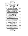
図9に示すように、実施例1における画像処理装置10は、表示対象領域設定要求とともに、画像表示要求を、入力部11を介して、操作者から受け付けると(ステップS901肯定)、組織画像生成部14aは、3次元データ記憶部13が記憶する3次元組織データを直交座標系に座標変換し(ステップS902)、座標変換された3次元組織データからボリュームレンダリングにより深度値を含む組織画像を生成する(ステップS903)。
As illustrated in FIG. 9, when the
そして、血流データ変換部14bは、3次元データ記憶部13が記憶する3次元血流データにおける血流を粒子により離散化して3次元粒子データに変換し(ステップS904)、血流画像生成部14cは、血流データ変換部14bによって生成された3次元粒子データにおける粒子をポリゴン表現する(ステップS905)。
Then, the blood flow
続いて、血流画像生成部14cは、3次元粒子データを直交座標系に座標変換し(ステップS906)、座標変換された3次元粒子データから投影処理により深度値を含む血流画像を生成する(ステップS907)。
Subsequently, the blood flow
そののち、合成画像生成部14dは、組織画像に含まれる各画素の深度値と、血流画像に含まれる各粒子の深度値とに基づいて、粒子と組織とを描出する順位を調整したうえで合成画像を生成する(ステップS908)。
After that, the composite
そして、表示制御部16は、合成画像を出力部12が備えるモニタにて順次表示するように制御し(ステップS909)、処理を終了する。こののち、画像処理装置10の操作者によって、合成画像を任意の方向に回転移動させた画像表示が行なわれる場合もある。
Then, the
なお、血流情報に基づく粒子の配置密度変更処理を実行する場合は、ステップS904において血流データ変換部14bにより実行される。また、血流情報に基づく粒子の大きさの変更処理を実行する場合は、ステップS905において血流画像生成部14cにより実行される。また、血流情報に基づく粒子の色づけ変更処理を実行する場合は、ステップS907において血流画像生成部14cにより実行される。
In addition, when executing the arrangement | positioning density change process of the particle | grains based on blood flow information, it is performed by the blood flow
また、図8にて説明した粒子の配置位置の変更処理は、ステップS904〜ステップS907を繰り返して実行することで行なわれる。 The particle arrangement position changing process described with reference to FIG. 8 is performed by repeatedly executing Steps S904 to S907.
また、本実施例では、組織画像の生成処理ののち血流画像の生成処理を行なう場合について説明したが、本発明はこれに限定されるものではなく、血流画像の生成処理ののち組織画像の生成処理を行なう場合であってもよい。あるいは、組織画像の生成処理と血流画像の生成処理とを並行して実行する場合であってもよい。 In the present embodiment, the case where the blood flow image generation process is performed after the tissue image generation process has been described. However, the present invention is not limited to this, and the tissue image is generated after the blood flow image generation process. The generation process may be performed. Alternatively, the tissue image generation process and the blood flow image generation process may be executed in parallel.
上述してきたように、実施例1では、組織画像生成部14aは、3次元データ記憶部13が記憶する3次元組織データからボリュームレンダリングにより深度値を含む組織画像を生成し、血流データ変換部14bは、3次元データ記憶部13が記憶する3次元血流データにおける血流を粒子により離散化して3次元粒子データに変換し、血流画像生成部14cは、3次元粒子データから深度値を含む血流画像を生成する。
As described above, in the first embodiment, the tissue
そして、合成画像生成部14dは、組織画像に含まれる各画素の深度値と、血流画像に含まれる各粒子の深度値とに基づいて、粒子と組織とを描出する順位を調整したうえで合成画像を生成し、表示制御部16は、合成画像を出力部12が備えるモニタにて順次表示するように制御するので、血流を粒子として表現することにより、3次元の血流分布を3次元の組織構造と重畳して表示しても、最前面の血流により、背面にある血流や組織構造が隠れてしまうことを回避することができ、上記した主たる特徴の通り、診断に適した形式で、血流を3次元的に表示することが可能になる。すなわち、医師などの操作者は、血流分布と組織構造とを両方観察することができ、診断を容易にすることが可能になる。
Then, the synthesized
また、合成画像を静止した状態で観察するのみならず、合成画像を任意の方向に回転させることにより、さらに立体感のある血流分布を観察でき、医師などの操作者は、血流分布と組織構造とを両方観察することができ、診断をより容易にすることが可能になる。 In addition to observing the synthesized image in a stationary state, rotating the synthesized image in an arbitrary direction enables observation of a more three-dimensional blood flow distribution. Both tissue structures can be observed, making diagnosis easier.
上述した実施例1では、組織画像と血流画像とを生成したうえで合成画像を生成する場合について説明したが、実施例2では、合成画像を一度に生成する場合について、図10を用いて説明する。図10は、実施例2における画像処理装置の構成を説明するための図である。 In the above-described first embodiment, the case where the composite image is generated after generating the tissue image and the blood flow image has been described. In the second embodiment, the case where the composite image is generated at once is described with reference to FIG. explain. FIG. 10 is a diagram for explaining the configuration of the image processing apparatus according to the second embodiment.
図10に示すように、実施例2における画像処理装置10は、実施例1における画像処理装置と同様に、超音波診断装置20と接続され、入力部11と、出力部12と、3次元データ記憶部13と、画像生成部14と、合成画像記憶部15と、表示制御部16とを備える。しかし、実施例2における画像生成部14は、実施例1における画像生成部14と異なり、組織画像生成部14aおよび血流画像生成部14cの代わりに合成データ生成部14eを備える。以下、これを中心に説明する。
As illustrated in FIG. 10, the
血流データ変換部14bは、実施例1と同様に、3次元データ記憶部13が記憶する3次元血流データにおける血流を粒子により離散化して3次元粒子データに変換する。
As in the first embodiment, the blood flow
合成データ生成部14eは、血流データ変換部14bによって生成された3次元粒子データと、3次元データ記憶部13が記憶する3次元組織データとを合成した合成データを生成する。その際、合成データ生成部14eは、3次元粒子情報と3次元組織構造情報とを識別するための識別情報を付与したうえで合成データを生成する。なお、合成データは、特許請求の範囲に記載の「合成情報」に対応する。
The synthetic
具体的には、合成データ生成部14eは、3次元組織データの入力階調は「0〜200」に制限し、3次元粒子データの入力階調は「255」の階調に制限したうえで、合成データを生成する。すなわち、入力階調の値を参照することで、3次元組織データを由来とするデータであるのか、3次元粒子データを由来とするデータであるのかを識別することができる。なお、合成データ生成部14eは、3次元粒子データから「3次元空間にて離散して配置される粒子の情報」以外の情報を間引いたデータを生成したうえで、合成データを生成する。
Specifically, the synthetic
合成画像生成部14dは、合成データ生成部14eによって生成された合成データに基づいて合成画像を生成する。すなわち、合成画像生成部14dは、血流を表す粒子の3次元情報が組織構造の3次元情報に埋め込まれた合成データを、直交座標系に座標変換したうえで、一度にボリュームレンダリングすることにより、「組織構造および血流」の情報を合成した合成画像を生成する。以下、合成画像の生成処理について説明する。
The composite
一般的に、ボリュームレンダリングでは、「i番目の断面」をレンダリングした後のフレームバッファへの書き込み内容「Pi」は、「Pi=[1-f(Ii)]Pi-1+g(Ii)」と表される。ここで、関数「f」は不透明度関数であり、関数「g」は伝達関数である。 In general, in volume rendering, the content “P i ” written to the frame buffer after rendering the “i th section” is “P i = [1-f (I i )] P i-1 + g (I i ) ”. Here, the function “f” is an opacity function, and the function “g” is a transfer function.
そこで、合成画像生成部14dは、ボリュームレンダリングに用いられる不透明度関数および伝達関数において、血流を表す粒子に対して特別な値を与えることで、合成画像を生成する。
Therefore, the composite
例えば、合成画像生成部14dは、合成データにおいて、入力値「Ii」が220以上の場合は、血流を表す粒子であるとして、不透明度関数「f(Ii)」の値を「1」とし、さらに、伝達関数「g(Ii)=(255, 0, 0)」となるように設定する。なお、伝達関数の括弧内の3つの値は、RGBカラーモードで色づけする際の「R(Red)」、「G(Green)」、「B(Blue)」それぞれの値を示す。すなわち、「g(Ii)=(255, 0, 0)」は、粒子の色を赤にて表現することを示している。なお、伝達関数の括弧内の3つの値を変更することで、血流情報に基づいた粒子の色や輝度の変更処理が可能となる。
For example, when the input value “I i ” is 220 or more in the composite data, the composite
また、合成画像生成部14dは、合成データにおいて、入力値「Ii」が220未満の場合は、組織構造を表すデータであるとして、組織構造に最適な不透明度関数「f(Ii)」を入力値に応じて設定し、さらに、組織構造をグレースケール表現するために、伝達関数の括弧内の3つの値を同じ値に設定する。これにより、合成画像生成部14dは、実施例1と同様に、組織構造と血流とを3次元表現する合成画像を1回のボリュームレンダリングで生成する(図6参照)。
In addition, when the input value “I i ” is less than 220 in the composite data, the composite
なお、3次元組織データを由来とするデータであるのか、3次元粒子データを由来とするデータであるのかを判定するための閾値を「200」ではなく「220」に設定しているのは、血流を離散化した粒子として表現するための補間処理を行なうためである。 The threshold for determining whether the data is derived from 3D tissue data or 3D particle data is set to “220” instead of “200”. This is because an interpolation process for expressing the blood flow as discrete particles is performed.
次に、図11を用いて、実施例2における画像処理装置10の処理について説明する。図11は、実施例2における画像処理装置の処理を説明するためのフローチャートである。
Next, processing of the
図11に示すように、実施例2における画像処理装置10は、実施例1と同様に、表示対象領域設定要求とともに、画像表示要求を、入力部11を介して、操作者から受け付けると(ステップS1101肯定)、血流データ変換部14bは、3次元データ記憶部13が記憶する3次元血流データにおける血流を粒子により離散化して3次元粒子データに変換する(ステップS1102)。
As illustrated in FIG. 11, the
そして、合成データ生成部14eは、血流データ変換部14bによって生成された3次元粒子データと、3次元データ記憶部13が記憶する3次元組織データとを合成した合成データを、入力階調を制限したうえで、生成する(ステップS1103)。
Then, the synthetic
続いて、合成画像生成部14dは、合成データ生成部14eによって生成された合成データを直交座標系に座標変換し(ステップS1104)、ボリュームレンダリングにより合成画像を生成する(ステップS1105)。
Subsequently, the composite
そして、表示制御部16は、合成画像を出力部12が備えるモニタにて順次表示するように制御し(ステップS1106)、処理を終了する。
Then, the
上述してきたように、実施例2では、合成画像を一回のボリュームレンダリングにより生成できるので、合成画像の表示処理を迅速に行なうことが可能になる。 As described above, in the second embodiment, since the composite image can be generated by one volume rendering, the composite image display process can be quickly performed.
なお、上述した実施例1では、3次元組織構造データをボリュームレンダリングによって3次元画像を生成して表示する場合について説明したが、本発明はこれに限定されるものではなく、3次元組織構造データにおける所定の断面に対応する断面組織画像を生成して表示する場合であってもよい。 In the first embodiment described above, the case where the 3D tissue structure data is generated and displayed by volume rendering has been described. However, the present invention is not limited to this, and the 3D tissue structure data is displayed. It may be a case where a cross-sectional tissue image corresponding to a predetermined cross section is generated and displayed.
心臓や胎児以外の部位の組織構造(例えば、肝臓の腫瘍部位など)は、ボリュームレンダリングによって、3次元構造を的確に表現できない場合がある。このような場合、組織構造を表現する画像としては、MPR(Multi Planar Reformat)画像を用いるほうが適している。 A tissue structure of a part other than the heart or fetus (for example, a tumor part of the liver) may not be able to accurately represent a three-dimensional structure by volume rendering. In such a case, it is more appropriate to use an MPR (Multi Planar Reformat) image as an image representing the tissue structure.
そこで、組織画像生成部14aは、3次元組織構造データから、入力部11を介して画像処理装置10の操作者から受け付けた断面に対応するMPR画像を生成し、合成画像生成部14cは、組織画像生成部14aによって生成されたMPR画像と、血流画像生成部14cによって生成された血流画像とを、被検体内の位置を合わせたうえで合成した合成画像を生成する。そして、表示制御部16は、生成された合成画像を、出力部12が備えるモニタにて表示するように制御する。
Therefore, the tissue
このように、MPR画像と血流画像とを合成した合成画像を生成して表示することで、ボリュームレンダリングによって3次元構造を的確に表現できない組織部位を血流とともに表示する場合においても、診断に適した形式で、血流を3次元的に表示することが可能になる。 As described above, by generating and displaying a composite image obtained by combining the MPR image and the blood flow image, even when displaying a tissue site that cannot accurately represent the three-dimensional structure by volume rendering together with the blood flow, The blood flow can be displayed three-dimensionally in a suitable format.
なお、上記したようにMPR画像を用いる場合も、実施例1と同様に、MPR画像と血流画像との深度値を用いて、組織構造と粒子で表現された血流との深さ方向の重なりを判定し、手前にある組織構造または粒子を優先させて描出するように調整したうえで、合成画像を生成する。あるいは、血流画像の透明度を上げた合成画像を生成してもよい。 In addition, also when using an MPR image as described above, as in the first embodiment, the depth values of the MPR image and the blood flow image are used in the depth direction between the tissue structure and the blood flow expressed by the particles. After determining the overlap and adjusting so as to preferentially draw the tissue structure or particles in the foreground, a composite image is generated. Or you may produce | generate the synthesized image which raised the transparency of the blood-flow image.
実施例3では、3次元血流データから3次元粒子データを、上述した実施例1および2とは異なる方法により生成する場合について、図12および図13を用いて説明する。図12は、実施例3における3次元粒子データの生成法について説明するための図であり、図13は、実施例3における合成画像生成部を説明するための図である。 In the third embodiment, a case where the three-dimensional particle data is generated from the three-dimensional blood flow data by a method different from the first and second embodiments will be described with reference to FIGS. 12 and 13. FIG. 12 is a diagram for explaining a method for generating three-dimensional particle data in the third embodiment, and FIG. 13 is a diagram for explaining a composite image generation unit in the third embodiment.
なお、以下に説明する実施例3の画像処理装置10における3次元粒子データの生成法は、図2を用いて説明した実施例1における画像処理装置10の血流データ変換部14bおよび図10を用いて説明した実施例2における画像処理装置10の血流データ変換部14bのいずれにおいても、適用可能である。
The method for generating three-dimensional particle data in the
上述した実施例1および2では、3次元血流データにて血流が存在する範囲に粒子を離散して配置することにより3次元粒子データを生成した。しかし、実施例3では、3次元血流データにて血流が存在する範囲を所定の間隔で除去することにより3次元粒子データを生成する。 In Examples 1 and 2 described above, three-dimensional particle data is generated by discretely arranging particles in a range where blood flow exists in the three-dimensional blood flow data. However, in the third embodiment, three-dimensional particle data is generated by removing a range where blood flow exists in the three-dimensional blood flow data at a predetermined interval.
具体的には、実施例3における血流データ変換部14bは、図12に示すように、3次元血流データ(奥行きを有する血流の3次元情報)を、空間的および時間的に変化する乱数により、合成画像の各画素にて表示するか否か(表示/非表示)を決定する。
Specifically, the blood flow
空間的および時間的に変化する乱数を用いて表示/非表示を決定することで、実施例3における血流データ変換部14bは、実施例1および2で説明した3次元粒子データと同様に、3次元血流データが離散した粒子にて変換された3次元粒子データを生成する。また、空間的のみならず、時間的にも変化する乱数を用いることにより、実施例3における血流データ変換部14bは、粒子が時系列に沿って移動する3次元粒子データを生成する。
By determining display / non-display using random numbers that change spatially and temporally, the blood flow
ここで、表示すると決定された画素に配置される粒子の形状は、図12に示すように、立方体の形状であってもよいが、本発明はこれに限定されるものではなく、例えば、球体など、任意の形状が操作者により設定可能である。 Here, the shape of the particles arranged in the pixels determined to be displayed may be a cubic shape as shown in FIG. 12, but the present invention is not limited to this. Any shape can be set by the operator.
また、実施例3における血流データ変換部14bは、実施例1または2にて説明した場合と同様に、3次元粒子データにおける粒子の色、粒子の配置密度、粒子の大きさなどを、血流の速度値、血流の速度値の分散値、血流のパワーに応じて変化するように、3次元粒子データを生成してもよい。
In addition, the blood flow
そして、血流データ変換部14bによって生成された3次元粒子データは、実施例1または実施例2において説明した処理により、組織画像との合成画像として生成される。すなわち、実施例1に本実施例を適用した場合、血流画像生成部14cは、血流データ変換部14bによって生成された3次元粒子データから深度値を含む血流画像を生成し、合成画像生成部14dは、組織画像に含まれる各画素の深度値と、血流画像に含まれる各画素の深度値とに基づいて、粒子と組織とを描出する順位を調整したうえで、合成画像を生成する。
Then, the three-dimensional particle data generated by the blood flow
あるいは、実施例2に本実施例を適用した場合、合成データ生成部14eは、血流データ変換部14bによって生成された3次元粒子データと、3次元組織データとを合成した合成データを生成し、合成画像生成部14dは、合成データを一回のボリュームレンダリング処理により合成画像を生成する。
Alternatively, when the present embodiment is applied to the second embodiment, the combined
ここで、実施例3における合成画像生成部14dは、例えば、1/4秒ごとに変化する乱数により1秒間に3次元粒子データが4回生成される場合に、図13に示すように、最初の1回(t=0)では3次元血流データから合成画像を生成し、他の3回(t=1/4、2/4、3/4)では3次元粒子データから合成画像を生成する。これにより、出力部12のモニタにおいては、最初に血流の全体像が表示され、そののち血流により隠れていた後ろの組織像が観察可能な合成画像が表示される。なお、図12および図13においては、腎臓における組織のMPR像と血流画像との合成画像を示している。
Here, for example, when the three-dimensional particle data is generated four times per second using a random number that changes every ¼ second, the composite
上述してきたように実施例3では、乱数により3次元血流データの一部を除去するだけで3次元粒子データを生成するので、血流分布と組織構造とを両方観察することができる合成画像を簡易に生成することが可能になる。 As described above, in the third embodiment, three-dimensional particle data is generated simply by removing a part of the three-dimensional blood flow data using a random number, and therefore, a composite image that can observe both the blood flow distribution and the tissue structure. Can be generated easily.
また、実施例3では、乱数を空間的および時間的に変化させることにより、例えば、1回超音波をスキャンすることで生成された静止画像のデータであっても、血液が流動している状態を表現できる合成画像を生成することが可能となる。また、実施例3では、例えば、3次元的に手前にある血流ほど表示される粒子の密度が大きくような乱数を発生させるように制御することで、合成画像における血流の立体感を向上させることが可能となる。 Further, in the third embodiment, by changing the random number spatially and temporally, for example, even in the case of still image data generated by scanning ultrasound once, the blood is flowing Can be generated. Further, in the third embodiment, for example, by controlling so as to generate a random number such that the density of particles displayed in the three-dimensional bloodstream is closer, the stereoscopic effect of the blood flow in the composite image is improved. It becomes possible to make it.
また、実施例3では、3次元組織データとの合成対象を、一定の間隔にて
3次元血流データとするので、画像診断を行なう医師は、残像として血流の全体像が記憶に残っている間に、血流分布と組織構造とを一度に観察することができる合成画像を参照することができ、正確な診断を行なうことが可能になる。
In the third embodiment, since the synthesis target with the three-dimensional tissue data is set to the three-dimensional blood flow data at a constant interval, the doctor who performs the image diagnosis leaves the entire blood flow image in the memory as an afterimage. During this time, it is possible to refer to a composite image in which the blood flow distribution and the tissue structure can be observed at a time, and an accurate diagnosis can be performed.
なお、上記した実施例1〜3では、画像処理装置10が、超音波診断装置20と分離されて設置される場合について説明したが、本発明はこれに限定されるものではなく、超音波診断装置20が、画像処理装置10の機能を備える場合であってもよい。
In the first to third embodiments, the case where the
また、上記した実施例1〜3では、画像処理装置10が、超音波診断装置20から3次元組織データおよび3次元血流データを取得して処理する場合について説明したが、本発明はこれに限定されるものではなく、超音波診断装置20などの医用画像診断装置が生成したデータを格納する医用画像データベースから3次元組織データおよび3次元血流データを取得して処理する場合であってもよい。
In the first to third embodiments, the case where the
また、図示した各装置の各構成要素は機能概念的なものであり、必ずしも物理的に図示の如く構成されていることを要しない。すなわち、各装置の分散・統合の具体的形態は図示のものに限られず、その全部または一部を、各種の負荷や使用状況などに応じて、任意の単位で機能的または物理的に分散・統合して構成することができる。さらに、各装置にて行なわれる各処理機能は、その全部または任意の一部が、CPUおよび当該CPUにて解析実行されるプログラムにて実現され、あるいは、ワイヤードロジックによるハードウェアとして実現され得る。 Each component of each illustrated device is functionally conceptual and does not necessarily need to be physically configured as illustrated. In other words, the specific form of distribution / integration of each device is not limited to that shown in the figure, and all or a part thereof may be functionally or physically distributed or arbitrarily distributed in arbitrary units according to various loads or usage conditions. Can be integrated and configured. Further, all or any part of each processing function performed in each device may be realized by a CPU and a program analyzed and executed by the CPU, or may be realized as hardware by wired logic.
以上のように、本発明に係る画像処理装置、画像処理方法および画像処理プログラムは、被検体内に対して送信した超音波の反射波に基づいて取得された当該被検体内にある組織の3次元組織構造データおよび当該被検体内を移動する血流の3次元血流データを用いて生成した画像を表示する場合に有用であり、特に、診断に適した形式で、血流を3次元的に表示することに適する。 As described above, the image processing apparatus, the image processing method, and the image processing program according to the present invention provide the 3 of the tissue in the subject acquired based on the reflected wave of the ultrasonic wave transmitted to the subject. This is useful when displaying an image generated using three-dimensional blood flow data of a three-dimensional tissue structure data and a blood flow moving in the subject. In particular, the blood flow is three-dimensionally displayed in a format suitable for diagnosis. Suitable for displaying.
10 画像処理装置
11 入力部
12 出力部
13 3次元データ記憶部
14 画像生成部
14a 組織画像生成部
14b 血流データ変換部
14c 血流画像生成部
14d 合成画像生成部
15 合成画像記憶部
16 表示制御部
20 超音波診断装置
21 超音波プローブ
22 送信部
23 受信部
24 Bモード処理部
25 カラードプラ処理部
26 制御部
DESCRIPTION OF
Claims (12)
前記画像生成部によって生成された前記合成画像を、所定の表示部にて表示するように制御する表示制御部と、
を備えたことを特徴とする画像処理装置。 Obtaining the three-dimensional tissue structure information of the tissue in the subject generated based on the reflected wave of the ultrasonic wave transmitted to the subject and the three-dimensional fluid information of the fluid moving in the subject; The three-dimensional particle information obtained by converting the three-dimensional fluid information is generated by discretely arranging a plurality of particles in a three-dimensional space in a range where the fluid exists in the three-dimensional fluid information, and the generated three An image generator that generates a composite image based on the three-dimensional particle information and the three-dimensional tissue structure information;
A display control unit for controlling the composite image generated by the image generation unit to be displayed on a predetermined display unit;
An image processing apparatus comprising:
前記表示制御部は、前記画像生成手段によって順次生成された前記合成画像を、前記所定の表示部にて順次表示するように制御することを特徴とする請求項1に記載の画像処理装置。 The image generation unit sequentially generates three-dimensional particle position change information in which the position where the particles are arranged in the three-dimensional particle information is changed at predetermined time intervals, and the generated three-dimensional particle position change information is sequentially generated. And sequentially generating the composite image based on the three-dimensional tissue structure information,
The image processing apparatus according to claim 1, wherein the display control unit controls the composite images sequentially generated by the image generation unit to be sequentially displayed on the predetermined display unit.
前記表示制御部は、前記画像生成手段によって生成された前記合成画像を、前記所定の表示部にて表示するように制御することを特徴とする請求項1に記載の画像処理装置。 The image generation unit generates a cross-sectional tissue image corresponding to a predetermined cross section in the three-dimensional tissue structure information, and generates the generated cross-sectional tissue image and the image using the three-dimensional particle information in the subject. Generate a composite image that is combined after positioning,
The image processing apparatus according to claim 1, wherein the display control unit controls the composite image generated by the image generation unit to be displayed on the predetermined display unit.
前記画像生成ステップによって生成された前記合成画像を、所定の表示部にて表示するように制御する表示制御ステップと、
を含んだことを特徴とする画像処理方法。 Obtaining the three-dimensional tissue structure information of the tissue in the subject generated based on the reflected wave of the ultrasonic wave transmitted to the subject and the three-dimensional fluid information of the fluid moving in the subject; The three-dimensional particle information obtained by converting the three-dimensional fluid information is generated by discretely arranging a plurality of particles in a three-dimensional space in a range where the fluid exists in the three-dimensional fluid information, and the generated three An image generating step for generating a composite image based on the three-dimensional particle information and the three-dimensional tissue structure information;
A display control step for controlling the composite image generated by the image generation step to be displayed on a predetermined display unit;
An image processing method comprising:
前記画像生成手順によって生成された前記合成画像を、所定の表示部にて表示するように制御する表示制御手順と、
をコンピュータに実行させることを特徴とする画像処理プログラム。 Obtaining the three-dimensional tissue structure information of the tissue in the subject generated based on the reflected wave of the ultrasonic wave transmitted to the subject and the three-dimensional fluid information of the fluid moving in the subject; The three-dimensional particle information obtained by converting the three-dimensional fluid information is generated by discretely arranging a plurality of particles in a three-dimensional space in a range where the fluid exists in the three-dimensional fluid information, and the generated three An image generation procedure for generating a composite image based on the three-dimensional particle information and the three-dimensional tissue structure information;
A display control procedure for controlling the composite image generated by the image generation procedure to be displayed on a predetermined display unit;
An image processing program for causing a computer to execute.
Priority Applications (1)
| Application Number | Priority Date | Filing Date | Title |
|---|---|---|---|
| JP2009080121A JP5366612B2 (en) | 2008-05-20 | 2009-03-27 | Image processing apparatus, image processing method, and image processing program |
Applications Claiming Priority (3)
| Application Number | Priority Date | Filing Date | Title |
|---|---|---|---|
| JP2008131834 | 2008-05-20 | ||
| JP2008131834 | 2008-05-20 | ||
| JP2009080121A JP5366612B2 (en) | 2008-05-20 | 2009-03-27 | Image processing apparatus, image processing method, and image processing program |
Publications (2)
| Publication Number | Publication Date |
|---|---|
| JP2010000340A true JP2010000340A (en) | 2010-01-07 |
| JP5366612B2 JP5366612B2 (en) | 2013-12-11 |
Family
ID=40940491
Family Applications (1)
| Application Number | Title | Priority Date | Filing Date |
|---|---|---|---|
| JP2009080121A Active JP5366612B2 (en) | 2008-05-20 | 2009-03-27 | Image processing apparatus, image processing method, and image processing program |
Country Status (4)
| Country | Link |
|---|---|
| US (1) | US9113811B2 (en) |
| EP (1) | EP2124197B1 (en) |
| JP (1) | JP5366612B2 (en) |
| CN (1) | CN101584589B (en) |
Cited By (1)
| Publication number | Priority date | Publication date | Assignee | Title |
|---|---|---|---|---|
| US9532949B2 (en) | 2011-07-19 | 2017-01-03 | Stc.Unm | Intraperitoneally-administered nanocarriers that release their therapeutic load based on the inflammatory environment of cancers |
Families Citing this family (24)
| Publication number | Priority date | Publication date | Assignee | Title |
|---|---|---|---|---|
| US8200466B2 (en) | 2008-07-21 | 2012-06-12 | The Board Of Trustees Of The Leland Stanford Junior University | Method for tuning patient-specific cardiovascular simulations |
| US20100168557A1 (en) * | 2008-12-30 | 2010-07-01 | Deno D Curtis | Multi-electrode ablation sensing catheter and system |
| US8948476B2 (en) * | 2010-12-20 | 2015-02-03 | St. Jude Medical, Atrial Fibrillation Division, Inc. | Determination of cardiac geometry responsive to doppler based imaging of blood flow characteristics |
| US8900150B2 (en) | 2008-12-30 | 2014-12-02 | St. Jude Medical, Atrial Fibrillation Division, Inc. | Intracardiac imaging system utilizing a multipurpose catheter |
| US9610118B2 (en) | 2008-12-31 | 2017-04-04 | St. Jude Medical, Atrial Fibrillation Division, Inc. | Method and apparatus for the cancellation of motion artifacts in medical interventional navigation |
| US9405886B2 (en) | 2009-03-17 | 2016-08-02 | The Board Of Trustees Of The Leland Stanford Junior University | Method for determining cardiovascular information |
| WO2011099410A1 (en) * | 2010-02-09 | 2011-08-18 | 株式会社 日立メディコ | Ultrasonic diagnosis device and ultrasonic image display method |
| JP5462076B2 (en) * | 2010-06-01 | 2014-04-02 | 株式会社東芝 | Ultrasonic diagnostic apparatus and image information management apparatus |
| JP2012016575A (en) * | 2010-06-07 | 2012-01-26 | Toshiba Corp | Image processing apparatus and medical image diagnosis apparatus |
| US8157742B2 (en) | 2010-08-12 | 2012-04-17 | Heartflow, Inc. | Method and system for patient-specific modeling of blood flow |
| US8315812B2 (en) | 2010-08-12 | 2012-11-20 | Heartflow, Inc. | Method and system for patient-specific modeling of blood flow |
| CN102521863B (en) * | 2011-12-01 | 2014-04-02 | 武汉大学 | Three-dimensional fluid scalar vector uniform dynamic showing method based on particle system |
| US8548778B1 (en) | 2012-05-14 | 2013-10-01 | Heartflow, Inc. | Method and system for providing information from a patient-specific model of blood flow |
| CN105451662B (en) * | 2013-08-09 | 2019-03-01 | 皇家飞利浦有限公司 | The method and system shown for medical imaging and information |
| EP3195806B1 (en) * | 2013-11-19 | 2022-04-06 | Versitech Limited | Apparatus for ultrasound flow vector imaging and methods thereof |
| CN110013272A (en) * | 2015-04-29 | 2019-07-16 | 深圳迈瑞生物医疗电子股份有限公司 | Display methods and ultrasonic image-forming system is imaged in supersonic blood |
| WO2016192114A1 (en) * | 2015-06-05 | 2016-12-08 | 深圳迈瑞生物医疗电子股份有限公司 | Ultrasonic fluid imaging method and ultrasonic fluid imaging system |
| EP3115766A1 (en) | 2015-07-10 | 2017-01-11 | 3Scan Inc. | Spatial multiplexing of histological stains |
| CN112704516B (en) * | 2015-08-04 | 2023-05-26 | 深圳迈瑞生物医疗电子股份有限公司 | Three-dimensional ultrasonic fluid imaging method and system |
| CN105260773B (en) * | 2015-09-18 | 2018-01-12 | 华为技术有限公司 | A kind of image processing apparatus and image processing method |
| US11043042B2 (en) * | 2016-05-16 | 2021-06-22 | Hewlett-Packard Development Company, L.P. | Generating a shape profile for a 3D object |
| JP6745237B2 (en) * | 2017-03-21 | 2020-08-26 | 株式会社日立製作所 | Ultrasonic diagnostic equipment |
| US10764555B2 (en) * | 2018-02-02 | 2020-09-01 | II William G. Behenna | 3-dimensional physical object dynamic display |
| USD938963S1 (en) * | 2020-02-21 | 2021-12-21 | Universität Zürich | Display screen or portion thereof with graphical user interface for visual clot display |
Citations (6)
| Publication number | Priority date | Publication date | Assignee | Title |
|---|---|---|---|---|
| JPH02305559A (en) * | 1989-05-20 | 1990-12-19 | Fujitsu Ltd | System for bringing blood flow into visible state |
| JPH03269679A (en) * | 1990-03-19 | 1991-12-02 | Fujitsu Ltd | Visualized display method for flow |
| JPH0592001A (en) * | 1991-10-03 | 1993-04-16 | Toshiba Corp | Ultrasonic diagnosing device |
| JPH09262236A (en) * | 1996-03-22 | 1997-10-07 | Advanced Technol Lab Inc | Ultrasonic diagnosis three-dimensional image processing method and device |
| WO2008008936A2 (en) * | 2006-07-13 | 2008-01-17 | The Regents Of The University Of Colorado | Echo particle image velocity (epiv) and echo particle tracking velocimetry (eptv) system and method |
| JP2008073297A (en) * | 2006-09-22 | 2008-04-03 | Olympia:Kk | Pinball game machine |
Family Cites Families (14)
| Publication number | Priority date | Publication date | Assignee | Title |
|---|---|---|---|---|
| US5608849A (en) * | 1991-08-27 | 1997-03-04 | King, Jr.; Donald | Method of visual guidance for positioning images or data in three-dimensional space |
| US5299174A (en) * | 1992-04-10 | 1994-03-29 | Diasonics, Inc. | Automatic clutter elimination |
| US5497776A (en) * | 1993-08-05 | 1996-03-12 | Olympus Optical Co., Ltd. | Ultrasonic image diagnosing apparatus for displaying three-dimensional image |
| US5810007A (en) * | 1995-07-26 | 1998-09-22 | Associates Of The Joint Center For Radiation Therapy, Inc. | Ultrasound localization and image fusion for the treatment of prostate cancer |
| US6256529B1 (en) * | 1995-07-26 | 2001-07-03 | Burdette Medical Systems, Inc. | Virtual reality 3D visualization for surgical procedures |
| JP3691895B2 (en) * | 1996-01-19 | 2005-09-07 | 株式会社日立メディコ | Ultrasonic diagnostic equipment |
| US6498607B1 (en) * | 1999-01-29 | 2002-12-24 | Mitsubishi Electric Research Laboratories, Inc. | Method for generating graphical object represented as surface elements |
| US6464642B1 (en) * | 1999-08-20 | 2002-10-15 | Kabushiki Kaisha Toshiba | Ultrasonic diagnosis apparatus |
| US7044913B2 (en) * | 2001-06-15 | 2006-05-16 | Kabushiki Kaisha Toshiba | Ultrasonic diagnosis apparatus |
| JP4761741B2 (en) * | 2004-09-06 | 2011-08-31 | 株式会社東芝 | X-ray CT apparatus, image data area extraction system, and image data area extraction program |
| US20070255138A1 (en) | 2006-04-27 | 2007-11-01 | General Electric Company | Method and apparatus for 3D visualization of flow jets |
| JP4878251B2 (en) | 2006-09-22 | 2012-02-15 | 日立アロカメディカル株式会社 | Ultrasonic diagnostic apparatus and ultrasonic image display method |
| JP5148094B2 (en) * | 2006-09-27 | 2013-02-20 | 株式会社東芝 | Ultrasonic diagnostic apparatus, medical image processing apparatus, and program |
| JP4417948B2 (en) | 2006-11-24 | 2010-02-17 | 株式会社日立製作所 | Railway vehicle drive control device |
-
2009
- 2009-03-27 JP JP2009080121A patent/JP5366612B2/en active Active
- 2009-05-12 US US12/464,472 patent/US9113811B2/en active Active
- 2009-05-13 CN CN200910140933XA patent/CN101584589B/en active Active
- 2009-05-15 EP EP09006615A patent/EP2124197B1/en active Active
Patent Citations (6)
| Publication number | Priority date | Publication date | Assignee | Title |
|---|---|---|---|---|
| JPH02305559A (en) * | 1989-05-20 | 1990-12-19 | Fujitsu Ltd | System for bringing blood flow into visible state |
| JPH03269679A (en) * | 1990-03-19 | 1991-12-02 | Fujitsu Ltd | Visualized display method for flow |
| JPH0592001A (en) * | 1991-10-03 | 1993-04-16 | Toshiba Corp | Ultrasonic diagnosing device |
| JPH09262236A (en) * | 1996-03-22 | 1997-10-07 | Advanced Technol Lab Inc | Ultrasonic diagnosis three-dimensional image processing method and device |
| WO2008008936A2 (en) * | 2006-07-13 | 2008-01-17 | The Regents Of The University Of Colorado | Echo particle image velocity (epiv) and echo particle tracking velocimetry (eptv) system and method |
| JP2008073297A (en) * | 2006-09-22 | 2008-04-03 | Olympia:Kk | Pinball game machine |
Cited By (1)
| Publication number | Priority date | Publication date | Assignee | Title |
|---|---|---|---|---|
| US9532949B2 (en) | 2011-07-19 | 2017-01-03 | Stc.Unm | Intraperitoneally-administered nanocarriers that release their therapeutic load based on the inflammatory environment of cancers |
Also Published As
| Publication number | Publication date |
|---|---|
| US20090292206A1 (en) | 2009-11-26 |
| JP5366612B2 (en) | 2013-12-11 |
| EP2124197B1 (en) | 2012-08-29 |
| CN101584589B (en) | 2013-05-22 |
| EP2124197A1 (en) | 2009-11-25 |
| CN101584589A (en) | 2009-11-25 |
| US9113811B2 (en) | 2015-08-25 |
Similar Documents
| Publication | Publication Date | Title |
|---|---|---|
| JP5366612B2 (en) | Image processing apparatus, image processing method, and image processing program | |
| JP5730196B2 (en) | Ultrasonic diagnostic apparatus, ultrasonic image processing apparatus, and ultrasonic image generation method | |
| JP5495357B2 (en) | Image display method and medical image diagnostic system | |
| US10157500B2 (en) | Utilizing depth from ultrasound volume rendering for 3D printing | |
| JP5770189B2 (en) | Ultrasonic diagnostic equipment | |
| JP5774498B2 (en) | Ultrasonic diagnostic equipment | |
| CN103220980B (en) | Ultrasound diagnostic apparatus and ultrasound image display method | |
| JP2009034521A (en) | System and method for volume rendering data in medical diagnostic imaging, and computer readable storage medium | |
| JP2009011711A (en) | Ultrasonic diagnosis apparatus | |
| JPWO2006030731A1 (en) | Ultrasonic imaging apparatus and projection image generation method | |
| JP2011104137A (en) | Ultrasonic diagnostic system | |
| JP2009018115A (en) | Three-dimensional ultrasonograph | |
| JP2008161289A (en) | Ultrasonic diagnostic apparatus | |
| JP2012005593A (en) | Ultrasound diagnostic apparatus for generating and displaying three-dimentional ultrasonic image | |
| KR101293744B1 (en) | The method and apparatus combining a plurality of 2-dimensional images with 3-dimensional model | |
| JP2009291295A5 (en) | ||
| JP2001276066A (en) | Three-dimensional image processor | |
| KR20140131808A (en) | Ultrasound imaging apparatus and control method for the same | |
| KR101107478B1 (en) | Ultrasound system and method for forming a plurality of 3 dimensional ultrasound images | |
| JP2010104784A (en) | Ultrasonic system and method of providing three-dimensional ultrasonic image | |
| JP2019205604A (en) | Blood flow image processor and method | |
| JP5583472B2 (en) | Medical image diagnostic apparatus and control program | |
| KR102578754B1 (en) | Method of displaying a ultrasound image and apparatus thereof | |
| US20230181165A1 (en) | System and methods for image fusion | |
| JP2005278988A (en) | Ultrasonic image processing apparatus |
Legal Events
| Date | Code | Title | Description |
|---|---|---|---|
| A621 | Written request for application examination |
Free format text: JAPANESE INTERMEDIATE CODE: A621 Effective date: 20120314 |
|
| A977 | Report on retrieval |
Free format text: JAPANESE INTERMEDIATE CODE: A971007 Effective date: 20130528 |
|
| A131 | Notification of reasons for refusal |
Free format text: JAPANESE INTERMEDIATE CODE: A131 Effective date: 20130611 |
|
| A521 | Written amendment |
Free format text: JAPANESE INTERMEDIATE CODE: A523 Effective date: 20130730 |
|
| TRDD | Decision of grant or rejection written | ||
| A01 | Written decision to grant a patent or to grant a registration (utility model) |
Free format text: JAPANESE INTERMEDIATE CODE: A01 Effective date: 20130820 |
|
| A61 | First payment of annual fees (during grant procedure) |
Free format text: JAPANESE INTERMEDIATE CODE: A61 Effective date: 20130910 |
|
| R150 | Certificate of patent or registration of utility model |
Ref document number: 5366612 Country of ref document: JP Free format text: JAPANESE INTERMEDIATE CODE: R150 Free format text: JAPANESE INTERMEDIATE CODE: R150 |
|
| S111 | Request for change of ownership or part of ownership |
Free format text: JAPANESE INTERMEDIATE CODE: R313117 |
|
| R350 | Written notification of registration of transfer |
Free format text: JAPANESE INTERMEDIATE CODE: R350 |
|
| S533 | Written request for registration of change of name |
Free format text: JAPANESE INTERMEDIATE CODE: R313533 |
|
| R350 | Written notification of registration of transfer |
Free format text: JAPANESE INTERMEDIATE CODE: R350 |