JP2009545295A - RF power transmission network and method - Google Patents
RF power transmission network and method Download PDFInfo
- Publication number
- JP2009545295A JP2009545295A JP2009522795A JP2009522795A JP2009545295A JP 2009545295 A JP2009545295 A JP 2009545295A JP 2009522795 A JP2009522795 A JP 2009522795A JP 2009522795 A JP2009522795 A JP 2009522795A JP 2009545295 A JP2009545295 A JP 2009545295A
- Authority
- JP
- Japan
- Prior art keywords
- power
- network
- tapping component
- antenna
- transmitter
- Prior art date
- Legal status (The legal status is an assumption and is not a legal conclusion. Google has not performed a legal analysis and makes no representation as to the accuracy of the status listed.)
- Pending
Links
- 230000005540 biological transmission Effects 0.000 title claims abstract description 54
- 238000000034 method Methods 0.000 title claims description 13
- 238000010079 rubber tapping Methods 0.000 claims abstract description 100
- 230000002457 bidirectional effect Effects 0.000 claims description 15
- 230000006854 communication Effects 0.000 claims description 7
- 238000004891 communication Methods 0.000 claims description 7
- 230000001965 increasing effect Effects 0.000 claims description 4
- 230000007246 mechanism Effects 0.000 claims description 4
- 230000003247 decreasing effect Effects 0.000 claims description 3
- 230000008878 coupling Effects 0.000 description 6
- 238000010168 coupling process Methods 0.000 description 6
- 238000005859 coupling reaction Methods 0.000 description 6
- 230000008901 benefit Effects 0.000 description 4
- 238000012423 maintenance Methods 0.000 description 4
- 230000008859 change Effects 0.000 description 3
- 238000010586 diagram Methods 0.000 description 3
- 238000005516 engineering process Methods 0.000 description 3
- 230000005855 radiation Effects 0.000 description 3
- 238000013461 design Methods 0.000 description 2
- 238000003780 insertion Methods 0.000 description 2
- 230000037431 insertion Effects 0.000 description 2
- ZCJJIQHVZCFSGZ-UHFFFAOYSA-N 2,8-bis(diphenylphosphoryl)dibenzothiophene Chemical compound C=1C=CC=CC=1P(C=1C=C2C3=CC(=CC=C3SC2=CC=1)P(=O)(C=1C=CC=CC=1)C=1C=CC=CC=1)(=O)C1=CC=CC=C1 ZCJJIQHVZCFSGZ-UHFFFAOYSA-N 0.000 description 1
- 238000007792 addition Methods 0.000 description 1
- 230000007175 bidirectional communication Effects 0.000 description 1
- 230000009977 dual effect Effects 0.000 description 1
- 230000005684 electric field Effects 0.000 description 1
- 230000001939 inductive effect Effects 0.000 description 1
- 238000009434 installation Methods 0.000 description 1
- 238000012986 modification Methods 0.000 description 1
- 230000004048 modification Effects 0.000 description 1
- 230000008569 process Effects 0.000 description 1
- 239000007787 solid Substances 0.000 description 1
- 238000012546 transfer Methods 0.000 description 1
Images


Classifications
-
- H—ELECTRICITY
- H04—ELECTRIC COMMUNICATION TECHNIQUE
- H04W—WIRELESS COMMUNICATION NETWORKS
- H04W52/00—Power management, e.g. TPC [Transmission Power Control], power saving or power classes
- H04W52/04—TPC
- H04W52/38—TPC being performed in particular situations
- H04W52/42—TPC being performed in particular situations in systems with time, space, frequency or polarisation diversity
-
- H—ELECTRICITY
- H02—GENERATION; CONVERSION OR DISTRIBUTION OF ELECTRIC POWER
- H02J—CIRCUIT ARRANGEMENTS OR SYSTEMS FOR SUPPLYING OR DISTRIBUTING ELECTRIC POWER; SYSTEMS FOR STORING ELECTRIC ENERGY
- H02J50/00—Circuit arrangements or systems for wireless supply or distribution of electric power
- H02J50/001—Energy harvesting or scavenging
-
- H—ELECTRICITY
- H02—GENERATION; CONVERSION OR DISTRIBUTION OF ELECTRIC POWER
- H02J—CIRCUIT ARRANGEMENTS OR SYSTEMS FOR SUPPLYING OR DISTRIBUTING ELECTRIC POWER; SYSTEMS FOR STORING ELECTRIC ENERGY
- H02J50/00—Circuit arrangements or systems for wireless supply or distribution of electric power
- H02J50/20—Circuit arrangements or systems for wireless supply or distribution of electric power using microwaves or radio frequency waves
-
- H—ELECTRICITY
- H02—GENERATION; CONVERSION OR DISTRIBUTION OF ELECTRIC POWER
- H02J—CIRCUIT ARRANGEMENTS OR SYSTEMS FOR SUPPLYING OR DISTRIBUTING ELECTRIC POWER; SYSTEMS FOR STORING ELECTRIC ENERGY
- H02J50/00—Circuit arrangements or systems for wireless supply or distribution of electric power
- H02J50/40—Circuit arrangements or systems for wireless supply or distribution of electric power using two or more transmitting or receiving devices
-
- H04B5/26—
-
- H04B5/79—
Abstract
【課題】RF電力伝送ネットワークが開示される。
【解決手段】ネットワークは、少なくとも1つのRF電力送信機と、少なくとも1つの電力タッピング構成要素と、少なくとも1つの負荷とを含む。前記少なくとも1つのRF電力送信機、前記少なくとも1つの電力タッピング構成要素、及び前記少なくとも1つの負荷は、直列に接続される。RF電力送信機は、ネットワークを介して電力を送る。電力は、充電、再充電、又は直接電力が与えられることになるデバイスによって受け取られるように、ネットワークから放射される。
【選択図】 図1An RF power transmission network is disclosed.
The network includes at least one RF power transmitter, at least one power tapping component, and at least one load. The at least one RF power transmitter, the at least one power tapping component, and the at least one load are connected in series. The RF power transmitter sends power over the network. Power is radiated from the network to be received by a device that will be charged, recharged, or directly powered.
[Selection] Figure 1
Description
[0001] 本発明は、直列無線周波数(RF)電力伝送ネットワークに関する。 [0001] The present invention relates to a serial radio frequency (RF) power transmission network.
[0002] プロセッサ機能が拡張され、電力の要件が減少するにつれて、配線又は電源コードとはまったく無関係に動作するデバイスが急増し続けている。これらの「非接続(untethered)」デバイスには、携帯電話及びワイヤレス・キーボードから建物センサ及びアクティブ無線周波数識別(RFID)タグまである。 [0002] As processor capabilities are expanded and power requirements are reduced, the number of devices that operate completely independent of wiring or power cords continues to increase rapidly. These “untered” devices range from cell phones and wireless keyboards to building sensors and active radio frequency identification (RFID) tags.
[0003] これらの非接続デバイスの技術者及び設計者は、主に、主要な設計パラメータとしてバッテリーを使用することで、引き続きポータブル電源の制約に対処しなければならない。プロセッサ及びポータブル・デバイスの性能は18〜24カ月ごとに倍増している(ムーアの法則による)が、容量に関するバッテリー技術は毎年6%しか向上していない。 [0003] Engineers and designers of these unconnected devices must continue to address the limitations of portable power sources, primarily using batteries as the primary design parameter. While the performance of processors and portable devices doubles every 18-24 months (according to Moore's Law), battery technology for capacity is only improving by 6% annually.
[0004] たとえ電力を意識した設計を使用し、さらに最新のバッテリー技術であっても、多くのデバイスは、物流及びビル・オートメーションなどの、多数の非接続デバイスを必要とする用途に関して、生涯コスト及び保守要件を満たすものではない。双方向通信を必要とする現在のデバイスは、デバイスの電源(通常は、バッテリー)を交換又は再充電するために、3カ月から18カ月ごとにスケジューリングされた保守を必要とする。自動ユーティリティ・メータ・リーダなどの、いかなる信号も受信せずに単にその状態をブロードキャストするだけの単方向デバイスは、通常は10年以内の交換が必要な、より長いバッテリー寿命を有する。どちらのデバイス・タイプの場合も、スケジューリングされた電源保守は費用がかかり、デバイスが監視及び/又は制御するように企図されているシステム全体を破壊する可能性がある。スケジューリングされていない保守の失敗は、さらに費用がかかり、破壊的である。マクロ・レベルでは、内部バッテリーに関連する比較的高いコストも、配置可能なデバイスの、実際的な、又は経済的に採算の合う数を減らしてしまう。 [0004] Even with power-aware designs and even the latest battery technology, many devices have lifetime costs for applications that require a large number of disconnected devices, such as logistics and building automation. And does not meet maintenance requirements. Current devices that require bi-directional communication require scheduled maintenance every 3 to 18 months to replace or recharge the device's power supply (usually a battery). Unidirectional devices that simply broadcast their status without receiving any signal, such as automated utility meter readers, have longer battery life that typically requires replacement within 10 years. For both device types, scheduled power maintenance is expensive and can destroy the entire system that the device is intended to monitor and / or control. Unscheduled maintenance failures are more expensive and disruptive. At the macro level, the relatively high costs associated with internal batteries also reduce the practical or economically profitable number of deployable devices.
[0005] 非接続デバイスに関する電力問題の理想的な解決手段は、環境から十分なエネルギーを集めて利用することができるデバイス又はシステムである。利用されるエネルギーは、その後、非接続デバイスに直接電力を与えるか、又は電力供給を増大させることになる。しかしながら、環境内のエネルギーが少ないこと、及び専用のエネルギー供給を使用する機能を制限する現場の制約などにより、この理想的な解決手段の実施が必ずしも実用的であるとは限らない。 [0005] An ideal solution to the power problem for unconnected devices is a device or system that can collect and utilize sufficient energy from the environment. The energy utilized will then power the disconnected device directly or increase the power supply. However, the implementation of this ideal solution is not always practical due to the low energy in the environment and field constraints that limit the ability to use a dedicated energy supply.
[0006] これらの要素を考慮し、理想的な状況及びより制約的な環境のどちらにも解決策を提供するシステムが求められている。 [0006] In view of these factors, there is a need for a system that provides a solution for both ideal situations and more restrictive environments.
[0007] 以前の発明は、例えば、どちらも「Power Transmission Network」という名称であり、参照により本明細書に組み込むものとする、米国仮特許出願第60/683,991号及び第60/763,582号などのように、電力分配のための並列ネットワークに重点を置いていた。この技術を活用する多くの用途では、伝送線路、直列スイッチ、方向性カプラ(DC)、及びコネクタからの損失を容認できないため、これらの発明は直列ネットワークを探求しなかった。しかしなから、例えば、デスク・エリアなどの、同軸ケーブル・インフラストラクチャを備える小規模ネットワークか、あるいはRF電力を分配するためにビル内で新規又は既存の低損失同軸ケーブル・インフラストラクチャを使用する小規模ネットワークなどの用途では、これらの損失が容認可能であるか、又は最小限の可能性がある。 [0007] Previous inventions, for example, are both named “Power Transmission Network” and are hereby incorporated by reference into US Provisional Patent Applications Nos. 60 / 683,991 and 60/763. Emphasis was placed on parallel networks for power distribution, such as 582. In many applications utilizing this technology, these inventions have not explored series networks because losses from transmission lines, series switches, directional couplers (DC), and connectors are unacceptable. However, a small network with a coaxial cable infrastructure, such as a desk area, or a small or new low-loss coaxial cable infrastructure in a building to distribute RF power. In applications such as large scale networks, these losses may be acceptable or minimal.
[0008] 本発明の目的は、直列のRF電力ネットワークを提供することであり、ここでRF電力ネットワークは、デバイスを充電又は再充電するため、あるいはデバイスに直接電力を供給するために、デバイスにRF電力を供給するシステムの一部として実施することが好適である。 [0008] An object of the present invention is to provide a series RF power network, where the RF power network is used to charge or recharge the device or to supply power directly to the device. It is preferably implemented as part of a system that supplies RF power.
[0009] 直列ネットワークには、ある用途では、並列ネットワークと比較していくつかの利点がある。一例として、直列ネットワークを使用することで、伝送線路の量を減らすことができる。並列ネットワークでは、伝送線路は、通常、RF電力送信機から各アンテナに接続される。直列ネットワークでは、各アンテナは、直列に接続された伝送線路からある量の電力を取り去る。直列RF電力伝送ネットワークの他の利点は、ネットワークが容易にスケーラブルなことである。一例として、追加の電力タッピング構成要素を直列に加えることによって、又はネットワークの端部に追加の電力タッピング構成要素を加えることによって、追加のアンテナをネットワークに加えることが可能であり、これにより、直列の長さが増加する。 [0009] Serial networks have several advantages over parallel networks in certain applications. As an example, the amount of transmission lines can be reduced by using a serial network. In a parallel network, the transmission line is typically connected to each antenna from an RF power transmitter. In a series network, each antenna removes a certain amount of power from the transmission lines connected in series. Another advantage of a series RF power transmission network is that the network is easily scalable. As an example, additional antennas can be added to the network by adding additional power tapping components in series, or by adding additional power tapping components at the edge of the network, thereby The length of increases.
[0010] 本発明によって分配されるRF電力を受け取るために好適な、種々の負荷に対する高効率整流のための方法及び装置については、参照により本明細書に組み込むものとする、米国仮特許出願第60/729,792号に詳細に記載されている。 [0010] A method and apparatus for high efficiency commutation for various loads, suitable for receiving RF power distributed by the present invention, is incorporated herein by reference. No. 60 / 729,792 is described in detail.
[0011] 本発明は、RF電力伝送ネットワークに関する。ネットワークは、電力を生成するための第1のRF電力送信機を備える。ネットワークは、第1の電力送信機から受け取った電力を少なくとも第1の部分及び第2の部分に分割するための、第1のRF電力送信機に直列に電気的に接続された少なくとも1つの電力タッピング構成要素を備える。ネットワークは、第1の部分を受け取り、電力を送信するための、前記少なくとも1つの電力タッピング構成要素に電気的に接続された少なくとも1つのアンテナを備える。 The present invention relates to an RF power transmission network. The network comprises a first RF power transmitter for generating power. The network includes at least one power electrically connected in series with the first RF power transmitter for dividing the power received from the first power transmitter into at least a first portion and a second portion. With a tapping component. The network comprises at least one antenna electrically connected to the at least one power tapping component for receiving a first portion and transmitting power.
[0012] 本発明は、電力伝送のためのシステムに関連する。システムは、電力を生成するための第1のRF電力送信機を備える。システムは、第1のRF電力送信機から受け取った電力を少なくとも第1の部分及び第2の部分に分割するための、第1のRF電力送信機に直列に電気的に接続された少なくとも1つの電力タッピング構成要素を備える。システムは、第1の部分を受け取り、電力を送信するための、前記少なくとも1つの電力タッピング構成要素に電気的に接続された少なくとも1つのアンテナを備える。システムは、電力を与えられることになるデバイスを備える。システムは、前記デバイスに電気的に接続され、伝送された電力を受け取るように構成された受信アンテナを備える。 [0012] The present invention relates to a system for power transmission. The system comprises a first RF power transmitter for generating power. The system includes at least one electrically connected in series with the first RF power transmitter for dividing the power received from the first RF power transmitter into at least a first portion and a second portion. A power tapping component is provided. The system comprises at least one antenna electrically connected to the at least one power tapping component for receiving a first portion and transmitting power. The system comprises a device that will be powered. The system includes a receive antenna that is electrically connected to the device and configured to receive the transmitted power.
[0013] 本発明は、RF電力伝送のための方法に関する。この方法は、第1のRF電力送信機を使用して電力を生成するステップを含む。第1のRF電力送信機に直列に電気的に接続された少なくとも1つの電力タッピング構成要素を使用して、第1の電力送信機から受け取った電力を少なくとも第1の部分及び第2の部分に分割するステップを含む。前記少なくとも1つの電力タッピング構成要素に電気的に接続された少なくとも1つのアンテナによって、第1の部分を受け取るステップを含む。前記少なくとも1つのアンテナを使用して、電力を伝送するステップを含む。 [0013] The present invention relates to a method for RF power transmission. The method includes generating power using a first RF power transmitter. Using at least one power tapping component electrically connected in series with the first RF power transmitter, the power received from the first power transmitter is at least in the first portion and the second portion. Including a step of dividing. Receiving a first portion by at least one antenna electrically connected to the at least one power tapping component. Using the at least one antenna to transmit power.
[0014] 本発明は、直流を生成する無線電力ハーベスタ(wireless power harvester)を有する受信機への無線電力伝送のための装置に関する。この装置は、第1の電力を有する第1の入力を有する結合器(combiner)を備える。前記装置は、第2の電力を有する第2の入力を備える。前記装置は、第1の電力及び第2の電力それぞれよりも大きく、第1の電力と第2の電力の組合せである出力電力を有する出力を備える。前記装置は、前記出力に電気的に接続されたアンテナを備えており、該アンテナを介して前記出力電力が前記受信機に送信される。 The present invention relates to an apparatus for wireless power transmission to a receiver having a wireless power harvester that generates direct current. The apparatus comprises a combiner having a first input having a first power. The apparatus comprises a second input having a second power. The apparatus comprises an output having an output power that is greater than each of the first power and the second power and is a combination of the first power and the second power. The apparatus includes an antenna that is electrically connected to the output, through which the output power is transmitted to the receiver.
[0015] 本発明は、直流を生成する無線電力ハーベスタを有する受信機への無線電力伝送のための装置に関する。この装置は、主線路と主線路から距離dの2次線路とを有する、所望のレベルまで電力を増加又は減少するためのフィールド調整可能カプラを備える。前記装置は、距離dを変更する調整可能なメカニズムを備える。前記装置はアンテナを備えており、該アンテナを介して前記電力が前記受信機へと送信される。 The present invention relates to an apparatus for wireless power transmission to a receiver having a wireless power harvester that generates direct current. The apparatus comprises a field adjustable coupler for increasing or decreasing power to a desired level, having a main line and a secondary line at a distance d from the main line. The device comprises an adjustable mechanism that changes the distance d. The device includes an antenna through which the power is transmitted to the receiver.
[0026] 本発明の完全な理解は、全体を通じて類似の参照文字が類似の部材を識別する添付の図面に関連した以下の説明から得られる。 [0026] A complete understanding of the present invention can be obtained from the following description, taken in conjunction with the accompanying drawings, in which like reference characters identify like parts throughout.
[0027] 以下の説明では、「上方」、「下方」、「右」、「左」、「垂直」、「水平」、「上部」、「下部」、及びそれらの派生語は、図面内で配向された本発明に関するものとする。しかしながら、本発明は、そうでないことが明示的に指定されていない限り、様々な代替の変形及びステップ・シーケンスを想定可能であることを理解されたい。また、添付の図面に示され、以下の明細書で説明される特定のデバイス及びプロセスは、本発明の単なる例示的実施形態であることも理解されたい。従って、本明細書に開示された実施形態に関する特定の寸法及び他の物理的特徴は、限定的であるとみなされるものではない。 [0027] In the following description, “upper”, “lower”, “right”, “left”, “vertical”, “horizontal”, “upper”, “lower”, and their derivatives are referred to in the drawings. It shall relate to the oriented invention. However, it should be understood that the present invention can assume various alternative variations and step sequences, unless expressly specified otherwise. It is also to be understood that the specific devices and processes illustrated in the accompanying drawings and described in the following specification are merely exemplary embodiments of the invention. Accordingly, specific dimensions and other physical characteristics related to the embodiments disclosed herein are not to be considered limiting.
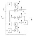
[0028] 本発明は、図1に示されるようなRF電力伝送ネットワーク10に関する。ネットワーク10は、電力を生成するための第1のRF電力送信機12aを備える。ネットワーク10は、第1の電力送信機12aから受け取った電力を少なくとも第1の部分及び第2の部分に分離するための、第1のRF電力送信機12aに直列に電気的に接続された少なくとも1つの電力タッピング構成要素14aを備える。ネットワークは、第1の部分を受け取るため及び電力を伝送するための、前記少なくとも1つの電力タッピング構成要素14aに電気的に接続された少なくとも1つのアンテナ20aを備える。
[0028] The present invention relates to an RF
[0029] 前記少なくとも1つの電力タッピング構成要素14aは、図3に示されるような方向性カプラ36とすることができる。ネットワーク10は、図2に示されるような、少なくとも1つの電力タッピング構成要素14aに直列に電気的に接続された第2のRF電力送信機12bを含むことができる。ネットワーク10は、第1のRF電力送信機12a、前記少なくとも1つの電力タッピング構成要素14a、前記少なくとも1つのアンテナ20a、及び第2のRF電力送信機12bのうちの1つ又は複数に電気的に接続された少なくとも1つのコントローラ74aを含むことができる。前記少なくとも1つの電力タッピング構成要素14aは、双方向性カプラ(bi-directional coupler)36とすることができる。別の方法としては、前記少なくとも1つの電力タッピング構成要素は、図4に示されるような電力分配器52とすることができる。
[0029] The at least one
[0030] ネットワーク10は、図2に示されるような、前記少なくとも1つの電力タッピング構成要素14aに直列に電気的に接続された少なくとも1つの追加のRF電力送信機12bを含むことができる。ネットワーク10は、第1のRF電力送信機12a、前記少なくとも1つの電力タッピング構成要素14a、前記少なくとも1つのアンテナ20a、及び前記少なくとも1つの追加のRF電力送信機12bのうちの1つ又は複数に電気的に接続された少なくとも1つのコントローラ74aを含むことができる。ネットワーク10は、終端負荷16を含むことができる。ネットワーク10は、少なくとも1つの伝送線路18を含むことができる。一実施形態では、第1のRF電力送信機12aから伝送される電力はデータを含まない。
[0030] The
[0031] ネットワーク10は、第1のRF電力送信機12a、前記少なくとも1つの電力タッピング構成要素14a、及び前記少なくとも1つのアンテナ20aのうちの1つ又は複数に電気的に接続された少なくとも1つのコントローラ74aを含むことができる。少なくとも1つのコントローラのうちの少なくとも1つのコントローラ74aは、少なくとも1つのコントローラのうちの少なくとも他のコントローラ74bに電気的に接続することができる。ネットワーク10は、前記少なくとも1つのアンテナ20aを介してパルスで(in pulses)電力を伝送するように構成することができる。
[0031] The
[0032] 前記少なくとも1つの電力タッピング構成要素14のうちの少なくとも1つは、図9に示されるように、スイッチ82aとすることができる。スイッチ82aは、制御線路を介して制御可能である。スイッチ82aは、電力を感知することによって制御することができる。感知される電力は電力のパルスとすることができる。電力のパルスは持続時間が変動する可能性がある。電力のパルスはタイミングが変動する可能性がある。スイッチ82aは、通信信号を介して制御することができる。通信信号は、同軸ケーブルを介して送信することができる。
[0032] At least one of the at least one power tapping component 14 may be a
[0033] アンテナ20aは、図1に示されるような伝送線路18とすることができる。第1のRF電力送信機12aから受け取られる電力の少なくとも一部は、前記少なくとも1つの電力タッピング構成要素14aによって、動作電力として使用されることが可能である。ネットワーク10は、前記少なくとも1つの電力タッピング構成要素14aに直列に電気的に接続された第2の電力タッピング構成要素14bを含むことができ、前記少なくとも1つの電力タッピング構成要素14aは、第1のRF電力送信機12aと第2の電力タッピング構成要素14bとの間に、配置される。第2の電力タッピング構成要素14bは、前記少なくとも1つの電力タッピング構成要素14aから第2の部分を受け取り、これを少なくとも第3の部分及び第4の部分に分割する。
[0033] The
[0034] 第1のRF送信機12aは、第1のRF電力送信機12aを前記少なくとも1つの電力タッピング構成要素14aに電気的に接続する第1のコネクタのみを含むことが可能である。前記少なくとも1つの電力タッピング構成要素14aは、前記少なくとも1つの電力タッピング構成要素を第2の電力タッピング構成要素14bに電気的に接続する第2のコネクタを含む。
[0034] The
[0035] 本発明は、図11に示されるような、電力伝送のためのシステム100に関する。前記システムは、電力を生成するための第1のRF電力送信機12aを備える。前記システムは、第1の電力送信機12aから受け取った電力を少なくとも第1の部分及び第2の部分に分割するための、第1のRF電力送信機12aに直列に電気的に接続された少なくとも1つの電力タッピング構成要素14aを備える。前記システムは、第1の部分を受け取り、電力を送信するための、前記少なくとも1つの電力タッピング構成要素14aに電気的に接続された少なくとも1つのアンテナ20aを備える。前記システムは、電力を与えられることになるデバイス94を備える。前記システムは、デバイス94に電気的に接続され、伝送された電力を受け取るように構成された受信アンテナ92を備える。
[0035] The present invention relates to a
[0036] ネットワーク10は、図1に示されるように、前記RF電力送信機、前記少なくとも1つの電力タッピング構成要素14a、及び前記少なくとも1つのアンテナ20aのうちの1つ又は複数に電気的に接続された少なくとも1つのコントローラ74aを含むことができる。前記少なくとも1つの電力タッピング構成要素のうちの少なくとも1つは、図9に示されるように、スイッチ82aとすることができる。システム100は、前記少なくとも1つのアンテナ20aを介してパルスで電力を伝送するように構成することができる。第1のRF電力送信機12aから受け取った電力の少なくとも一部は、前記少なくとも1つの電力タッピング構成要素14aによって、動作電力として使用されることが可能である。一実施形態では、第1のRF電力送信機12aから伝送される電力はデータを含まない。
[0036] The
[0037] 図11に示されるように、ネットワーク10は、前記少なくとも1つの電力タッピング構成要素14aに直列に電気的に接続された第2の電力タッピング構成要素14bを含むことができ、前記少なくとも1つの電力タッピング構成要素14aは、第1のRF電力送信機12aと第2の電力タッピング構成要素14bとの間に、配置される。第2の電力タッピング構成要素14bは、前記少なくとも1つの電力タッピング構成要素14aから第2の部分を受け取り、これを、少なくとも第3の部分及び第4の部分に分割する。第2のアンテナ20bは、第3の部分を受け取るため及び電力を伝送するために、第2の電力タッピング構成要素14bに電気的に接続される。
[0037] As shown in FIG. 11, the
[0038] 図3に示されるように、直流を生成する無線電力ハーベスタを有する受信機への無線電力伝送のための装置を含む。前記装置は、第1の電力を有する第1の入力40aを有する結合器38を備える。前記装置は、第2の電力を有する第2の入力40bを備える。前記装置は、第1の電力及び第2の電力それぞれよりも大きく、第1の電力と第2の電力の組合せである出力電力を有する出力を備える。前記装置は、前記出力に電気的に接続されたアンテナ20aを備えており、該アンテナ20aを介して前記出力電力が前記受信機に送信される。
[0038] As shown in FIG. 3, it includes an apparatus for wireless power transmission to a receiver having a wireless power harvester that generates direct current. The apparatus comprises a
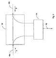
[0039] 図6に示されるように、直流を生成する無線電力ハーベスタを有する受信機への無線電力伝送のための装置を含む。前記装置は、主線路62と主線路62から距離dの2次線路64とを有する、所望のレベルまで電力を増加又は減少するためのフィールド調整可能カプラ60を備える。前記装置は、距離dを変更する調整可能なメカニズムを備える。前記装置はアンテナ20aを備えており、該アンテナ20aを介して前記電力が前記受信機へと送信される。
[0039] As shown in FIG. 6, it includes an apparatus for wireless power transmission to a receiver having a wireless power harvester that generates direct current. The apparatus includes a field adjustable coupler 60 having a
[0040] 本発明は、RF電力伝送のための方法に関する。この方法は、図11に示されるように、第1のRF電力送信機12aを使用して電力を生成するステップを含む。第1のRF電力送信機12aに直列に電気的に接続された少なくとも1つの電力タッピング構成要素14aを使用して、第1の電力送信機12aから受け取った電力を少なくとも第1の部分及び第2の部分に分割するステップを含む。前記少なくとも1つの電力タッピング構成要素14aに電気的に接続された少なくとも1つのアンテナ20aによって、第1の部分を受け取るステップを含む。前記少なくとも1つのアンテナ20aを使用して、電力を伝送するステップを含む。
[0040] The present invention relates to a method for RF power transmission. The method includes generating power using a first
[0041] 前記方法は、デバイス94に電気的に接続され、伝送された電力を受け取るように構成された受信アンテナ92で、前記少なくとも1つのアンテナ20aから無線伝送された電力を受け取るステップと、デバイス94に電気的に接続されたデバイス94内に配置された電力ハーベスタを使用して、受信アンテナ92によって受け取られた電力を変換するステップとを含むことができる。前記方法は、前記少なくとも1つの電力タッピング構成要素に直列に電気的に接続された第2の電力タッピング構成要素14bを追加するステップを含むことができ、前記少なくとも1つの電力タッピング構成要素14aは、第1のRF電力送信機12aと第2の電力タッピング構成要素14bとの間に、配置される。第2の電力タッピング構成要素14bは、前記少なくとも1つの電力タッピング構成要素14aから第2の部分を受け取り、これを少なくとも第3の部分及び第4の部分に分割する。第2の電力タッピング構成要素14bに電気的に接続された第2のアンテナ20bで、第3の部分を受け取るステップを含むことができる。第2のアンテナ20bから電力を伝送するステップを含むことができる。
[0041] The method includes receiving power wirelessly transmitted from the at least one
単一入力直列ネットワーク
[0042] 図1を全体として参照すると、単一入力(「単純」)直列電力分配/伝送ネットワーク10は、本発明に従って、単一RF電力送信機12a及び少なくとも1つの電力タッピング構成要素(PTC)14aを含む。単一入力直列ネットワーク10は、負荷16で終端する。PTC14a〜cは直列に接続される。
Single input series network
[0042] Referring generally to FIG. 1, a single input ("simple") series power distribution /
[0043] 電力は、RF電力送信機12aからD方向に移動する。それ故、単一入力直列ネットワーク10内には単一の電力方向が存在する。図1に示されるように、電力は左から右へと移動する。
[0043] Power moves in the D direction from the
[0044] ネットワーク10内の接続18(一般に、本明細書では伝送線路と呼ばれる)は、同軸ケーブル、伝送線路、導波路、又は他の好適な手段を介して作成される。負荷16は、アンテナ、終端装置、カプラ、方向性カプラ、双方向性カプラ、スプリッター、結合器、電力分配器、サーキュレータ、減衰器、又は負荷として働く任意の他の構成要素を含むことができるが、これらに限定されない。伝送線路18又は最終PTC14cは、負荷16を使用して、反射をなくすために終端されるものとする。サーキュレータ、並びにスプリッター及び結合器は、また、反射電力を直列接続内に再供給することも可能であることに留意されたい。
[0044]
[0045] PTC14aは、伝送線路18(又は他の接続)から電力を取り去り、取り去った電力を、負荷16、アンテナ20a、又は他の伝送線路18などの他の構成要素に供給する。好ましくはPTC14aは、残りの電力があれば、負荷16、アンテナ20a、他のPTC14b、又は他の伝送線路18などの、直列の次の構成要素にパスする。
[0045] The
[0046] 好ましくは、PTC14aは、電力が入力されるもの、出力されるもの(受け入れた分)、及び/又は出力されるもの(パスした分)の3つ又はそれ以上の入出力(コネクタ)を有する。例えば、PTC14aは、入力端、受け入れた電力用の第1の出力端、及びパスされた電力用の第2の出力端を有する。PTC14aは、入力端で電力を受け取る。PTC14aは、その電力を第1の部分及び第2の部分に分割する。第1の部分は「受け入れ」られ、第1の出力端に送られて、例えば、アンテナ20a(以下で説明)に送られる。第2の部分は「パス」され、直列の次の構成要素、例えば、他のPTC14bに送られる。
[0046] Preferably, the
[0047] PTC14aは、図1に示されるように、方向性カプラとすることができる。方向性カプラは、スプリッター又は結合器を使用して実施可能である。
[0047] As shown in FIG. 1, the
[0048] 各PTC14a〜cの1つの出力は、好ましくは、アンテナ20a〜cにそれぞれ接続される。各アンテナ20a〜cは、カバレッジ・エリア(又はボリューム)内に電力を放射する。カバレッジ・エリアは、最小電界及び/又は磁界強さによって定義される。一例として、カバレッジ・エリアは、放射される電界強さが1メートルあたり2ボルト(2V/m)より大きいエリア(又はスペース)として定義することができる。所与のアンテナ20aからのカバレッジ・エリアは、他のアンテナ20b、20cからの他のカバレッジ・エリアと重複する場合と、重複しない場合がある。各PTC14a〜cの他の出力は、負荷16及び他の伝送線路18に接続可能である。
[0048] One output of each
[0049] PTC14a〜cが方向性カプラとして実施される場合、方向性カプラは、伝送線路18からある割合(dB)をタッピングする(又は取り去る)ように設計することができる。例えば、−20dBカプラ及び1000ワット(W)入力は、結果として終端負荷16に10Wを出力することになる。ネットワーク10内の方向性カプラは、すべて同じカップリング(例えば、−20dB)を有するか、あるいは場合によって標準カップリング(例えば、−3、−6、−10dB)又は非標準カップリング(例えば、−3.4、−8、−9.8dB)を使用するように設計することができる。
[0049] When the
[0050] サーキュレータ22a又はアイソレータは、RF電力送信機12aに損傷を与えることになる反射電力から保護するために、RF電力送信機12と第1のPTC14aとの間で直列に接続することができる。
[0050] A
[0051] 図1は、RF電力送信機12a、サーキュレータ22a、それぞれアンテナ20a〜cに接続された3つのPTC14a〜c(方向性カプラとして実装される)、及び終端負荷16を備えた単一入力直列ネットワーク10を示す。
[0051] FIG. 1 shows a single input with an
[0052] 使用中、RF電力送信機12aは、ネットワーク10内で伝送線路18に沿って各PTC14a〜cへと電力を供給する。各PTC14a〜cは、線路から電力をタッピングし、その電力をそれぞれの接続されたアンテナ20a〜c、負荷16へと送る。アンテナ20a〜c、負荷16は、その電力を各アンテナ20a〜c、負荷16に対応するカバレッジ・エリアへ放射する。カバレッジ・エリア内にある場合、電力が与えられることになるデバイスは放射された電力を受け取る。受け取った電力は、デバイスを充電又は再充電するため、あるいはデバイスに直接電力を与えるために使用される。
In use, the
2入力直列ネットワーク
[0053] 図2を全体として参照すると、本発明による2入力直列電力分配/伝送ネットワーク10は、ネットワーク30の第1の端部32に第1のRF電力送信機12a、及びネットワーク10の第2の端部34に第2のRF電力送信機12bを含む。1つ又は複数のPTC14は、第1のRF電力送信機12aと第2のRF電力送信機12bとの間に直列に配置される。
2-input series network
Referring generally to FIG. 2, a two-input series power distribution /
[0054] 好ましくは、各PTC14が、また、それぞれのアンテナ20a〜cに接続される。各アンテナ20a〜cは、カバレッジ・エリア内に電力を放射する。所与のアンテナ20aからのカバレッジ・エリアは、他のアンテナ20b、20cからの他のカバレッジ・エリアと重複する場合、又は重複しない場合がある。
[0054] Preferably, each PTC 14 is also connected to a
[0055] PTC14a〜cは、双方向の波を結合する双方向性カプラとすることができる。これにより、第1のRF電力送信機12aから生じる第1の電力方向Aと、第2のRF電力送信機12bから生じる第2の電力方向Bとの2重電力方向が可能になる。
[0055] The
[0056] 第1のサーキュレータ22aは、第1のRF電力送信機12aに損傷を与えることになる反射電力から保護するために、第1のRF電力送信機12aと、直列の線路の隣のPTC14aとの間で、第1のRF電力送信機12aの隣に接続することができる。同様に、第2のサーキュレータ22bは、第2のRF電力送信機12bと、直列の線路の隣の対応PTC14bとの間に、配置することができる。
[0056] The
[0057] 第1のRF電力送信機12a及び第2のRF電力送信機12bは、同じ周波数とすることができる。しかしながら、構成要素の許容差により、実際にはわずかに異なる周波数となり、ある有限値を平均として、同相及び位相外れで(in and out of phase)ゆるやかに移動することになる。この問題については、どちらも「Power Transmission Network」という名称であり、参照により本明細書に組み込むものとする、米国特許出願第11/699,148号及び米国仮特許出願第60/763,582号に詳細に記載されている。第1のRF電力送信機12a及び第2のRF電力送信機12bは、また、異なる周波数であるか又は別のチャネル上にあるように設計することも可能である。
[0057] The first
[0058] 2つ(又は以下で説明するように、複数)のRF電力送信機12a、12bを備えたネットワーク10の利点は、ネットワーク10が、(単一入力直列ネットワーク10を使用する場合のように)損失を一方の端部に集中させるのではなく、損失を伝送線路18に沿って分散させることである。他の利点は、各RF電力送信機12a、12bが必要とする電力が少ないことである。例えば、単一の送信機12aが1000Wを入力可能であるか、又は2つの送信機12a、12bがそれぞれ500Wを入力可能である。2つの500Wの入力は、電力及び構成要素コストなどに関して、より安価なネットワーク10となる。RF電力送信機12a、12bは、有利であることがわかれば、異なる電力レベルを有することができる。
[0058] The advantage of the
[0059] 図2は、第1のRF電力送信機12a、第1のサーキュレータ22a、それぞれがアンテナ20aに接続された3つのPTC14a〜c(双方向性カプラとして実装)、第2のサーキュレータ22b、及び第2のRF電力送信機12bを有する2入力直列ネットワーク10を示す。
[0059] FIG. 2 shows a first
[0060] 使用中、RF電力送信機12a及び12bは、ネットワーク10内で伝送線路18に沿って各PTC14a〜cへと電力を供給する。各PTC14a〜cは、線路から電力をタッピングし、その電力をそれぞれの接続されたアンテナ20a〜cへと送る。アンテナ20a〜cは、その電力を各アンテナ20a〜cに対応するカバレッジ・エリアへ放射する。カバレッジ・エリア内にある場合、電力が与えられることになるデバイスは放射された電力を受け取る。受け取った電力は、デバイスを充電又は再充電するため、あるいはデバイスに直接電力を与えるために使用される。
[0060] In use, the
[0061] 図3を参照すると、所与の双方向性カプラ36は、各電力方向A、Bからの電力を結合するために、結合器38を必要とする可能性がある。第1の初期電力を有する第1の入力40aは、第1の電力方向Aから双方向性カプラ36に入る。第2の初期電力を有する第2の入力40bは、第2の電力方向Bから双方向性カプラ36に入る。第1の入力のタップ(例えば、−20dB)及び第2の入力のタップ(例えば、−20dB)は結合器38内で結合され、結合された電力42をアンテナ22a又は他の伝送線路18(あるいは、その2つの組合せ)へと出力する。
[0061] Referring to FIG. 3, a given bidirectional coupler 36 may require a
[0062] 双方向性カプラ36を離れた第1の入力は、他の双方向性カプラ36への入力となる可能性があり、タッピングされた電力量だけ、及びカプラ36それ自体の損失量(挿入損失)だけ減じられている。同じことが、双方向性カプラ36を離れた第2の入力にもあてはまる。言い換えれば、第1の入力40aが双方向性カプラ36を離れた場合、この時点の電力量は、初期の電力からタッピングされた量を引き去り、カプラ36内で失われた電力(挿入損失)を引き去った量に等しい。
[0062] The first input leaving the bi-directional coupler 36 may become an input to another bi-directional coupler 36, and only the amount of tapped power and the loss of the coupler 36 itself ( (Insertion loss) is reduced. The same applies to the second input off the bidirectional coupler 36. In other words, if the
[0063] 別の方法としては、双方向性カプラ36は、電力の方向を感知しないように、従って結合器38が不要なように設計される可能性がある。従って、PTC14a(この場合は、双方向性カプラ)は、単にカプラと名づけてもよい。
[0063] Alternatively, the bi-directional coupler 36 may be designed so that it does not sense the direction of power, and thus the
複数入力直列ネットワーク
[0064] 図4を全体として参照すると、本発明による複数入力直列電力分配/伝送ネットワーク10は、第1のRF電力送信機12aと、第2のRF電力送信機12bとを含み、また、例えば星形又はクラスタのパターンで電力分配器52を介して接続された第3のRF電力送信機12cを少なくとも含む。1つ又は複数のPTC14a〜cは、第1、第2、及び/又は第3のRF電力送信機12a〜cと、電力分配器52との間に直列に配置することができる。
Multiple input series network
[0064] Referring to FIG. 4 as a whole, a multiple-input serial power distribution /
[0065] 好ましくは、各PTC14a〜cは、それぞれアンテナ20a〜cにも接続される。各アンテナ20a〜cは、カバレッジ・エリア内に電力を放射する。所与のアンテナ20aからのカバレッジ・エリアは、他のアンテナ20b、20cからの他のカバレッジ・エリアと重複する場合、又は重複しない場合がある。
[0065] Preferably, each
[0066] PTC14a〜cは、2方向の波を結合する双方向性カプラとすることができる。電力分配器52は、複数方向の波を結合する(又は電力をルーティングする)。これにより、第1のRF電力送信機12aから生じる第1の電力方向Aと、第2のRF電力送信機12bから生じる第2の電力方向Bと、第3のRF電力送信機12cから生じる第3の電力方向Cとの複数電力方向が可能になる。電力分散器52は、結合器又はスプリッターとすることができる。2入力直列ネットワーク10(図2に図示)と比較すると、複数入力直列ネットワーク10では、ネットワーク10は、第1のRF電力送信機12aからの第1の入力40a及び第2のRF電力送信機12bからの第2の入力40bを含むだけでなく、第3のRF電力送信機12cからの第3の入力40cも少なくとも含む。
[0066] The
[0067] 図5を参照すると、電力分配器52上のポートの数は、1からN個までのスプリッターを使用することによって増やすことが可能であり、電力分配器52上にN+1個のポートが与えられる。1つのスプリッター54a上のそれぞれの出力が他のスプリッター54bの出力のうちの1つに接続される。例えば、図5に示されるように、3ポート電力分配器52は、3つの1対2スプリッター54a〜cを含む。方向Aからの電力は第1のポート56aから入り、スプリッター54aによって分割され、スプリッター54b及び54cに向けて送られる。方向Bからの電力は第2のポート56bから入り、スプリッター54bによって分割され、スプリッター54a及び54cに向けて送られる。方向Cからの電力は、第3のポート56cから入り、スプリッター54cによって分割され、スプリッター54a及び54bに向けて送られる。
[0067] Referring to FIG. 5, the number of ports on the
[0068] 図4に示された複数入力直列ネットワーク10は、種々の構成で接続された追加のRF電力送信機及び/又は追加の電力分配器を含むことができる。言い換えれば、ネットワーク10は、2以上の電力分配器52が複数のRF電力送信機12a〜cを接続するように拡張可能である。それ故、ネットワーク10は、複数の星形又はクラスタのパターンを含むことができる。
[0068] The multiple-input
[0069] 図4は、第1のRF電力送信機12a、第2のRF電力送信機12b、第3のRF電力送信機12c、及び電力分配器52を有する複数入力直列ネットワーク10を示す。第1のPTC14a(双方向性カプラとして実装)は、第1のRF電力送信機12aと電力分配器52との間に接続される。第2のPTC14bは、第2のRF電力送信機12bと電力分配器52との間に接続される。第3のPTC14cは、第3のRF電力送信機12cと電力分配器52との間に接続される。各PTC14a〜cは、また、アンテナ20aにも接続される。
[0069] FIG. 4 shows a multiple-input
[0070] 使用中、RF電力送信機12a〜cは、ネットワーク10内で伝送線路18に沿って各PTC14に電力を供給する。各PTC14a〜cは、線路からの電力をタッピングし、この電力をそれぞれ接続されたアンテナ20acに送る。アンテナ20a〜cは、各アンテナa〜cに対応するカバレッジ・エリアに電力を放射する。カバレッジ・エリア内にある場合、電力が与えられることになるデバイスは、放射された電力を受け取る。受け取られた電力は、デバイスを充電又は再充電するため、あるいはデバイスに直接電力を与えるために使用される。
In use, the RF power transmitters 12 a-c supply power to each PTC 14 along the
調整可能なPTC
[0071] 一般に、PTC14aを出る電力量は、PTC14aに入った電力量からPTC14aによってタッピングされた電力量だけ減じられた量に等しい。それ故、RF電力送信機12aからの初期の電力量は、PTC14a〜cを通る毎に減じられる。
Adjustable PTC
[0071] In general, the amount of power leaving the
[0072] 例えば、ネットワークは、−20dBカプラとして実装された2つのPTCを含む。第1のカプラへの入力が100Wの場合、タッピングされる量は1Wとなり(すなわち、100W/100=1W)、出て行く電力量は99Wとなる(すなわち、100W−1W=99W)。この99Wが第2の−20dBカプラに到達すると、タッピングされる量は0.99W(99W/100=0.99W)となり、第2のカプラを出て行く量は98.01Wとなる。 [0072] For example, the network includes two PTCs implemented as -20 dB couplers. When the input to the first coupler is 100 W, the tapped amount is 1 W (ie, 100 W / 100 = 1 W), and the outgoing power amount is 99 W (ie, 100 W−1W = 99 W). When 99W reaches the second −20 dB coupler, the tapped amount is 0.99 W (99 W / 100 = 0.99 W), and the amount leaving the second coupler is 98.01 W.
[0073] 図6を全体として参照すると、すべての出力を等しく、又は所望のレベルにするために、本発明と共にフィールド調整可能なPTC60を利用することができる。フィールド調整可能なPTC60は、カップリング係数を変化させることによって、電力を所望のレベルまで増加又は減少させることができる。 [0073] Referring to FIG. 6 as a whole, a field adjustable PTC 60 can be utilized with the present invention to bring all outputs equal or at a desired level. The field adjustable PTC 60 can increase or decrease the power to a desired level by changing the coupling factor.
[0074] 例えば、PTC60は双方向性カプラである。双方向性カプラを調整可能にするために、距離又は電気特性を変更するためのねじ又は電気式コントローラなどの調整メカニズムが導入されるが、これらに限定されない。カップリング係数は、双方向性カプラの主線路62と2次線路64との間の距離d、又はカプラの電気特性に依存する。カプラの長さの変更も特性を変化させることになることに留意されたい。
[0074] For example, the PTC 60 is a bidirectional coupler. In order to make the bi-directional coupler adjustable, an adjustment mechanism such as, but not limited to, a screw or electrical controller to change the distance or electrical characteristics is introduced. The coupling coefficient depends on the distance d between the
[0075] ネットワーク10内にフィールド調整可能なPTC60を含めることによって、ネットワーク10全体を通じて各アンテナに結合される電力をほぼ一定のレベルで維持することができる。
[0075] By including a field adjustable PTC 60 in the
[0076] 図7及び図8を参照すると、ネットワーク内に複数のパスが存在可能である。例えば、図7を参照すると、ネットワーク10は、第1のPTC14a(方向性カプラとして実装)及び電力スプリッター54(1対2)と共に直列に接続されたRF電力送信機12aを含む。電力スプリッター54の第1の出力は第2のPTC14bに接続され、第1の終端アンテナ(負荷)16bで終端する。電力スプリッター54の第2の出力は、第4のPTC14dと直列の第3のPTC14cに接続され、第2の終端アンテナ(負荷)16dで終端する。第1、第2、第3、及び第4のPTC14a〜dは、アンテナ(それぞれ、第1のアンテナ20a、第2のアンテナ20b、第3のアンテナ20c、及び第4のアンテナ20d)にそれぞれ接続され、種々のカバレッジ・エリア内に電力を放射するために、それぞれのアンテナ20a〜dに電力を結合する。カバレッジ・エリア内にある場合、電力が与えられることになるデバイスは放射された電力を受け取る。受け取った電力は、デバイスを充電又は再充電するため、あるいはデバイスに直接電力を与えるために使用される。
[0076] Referring to FIGS. 7 and 8, there can be multiple paths in the network. For example, referring to FIG. 7, the
[0077] 他の例の場合、図8を参照すると、ネットワーク10は、第1のPTC14a(方向性カプラとして実装)に接続されたサーキュレータ22と直列に接続されたRF電力送信機12aを含む。第1のPTC14aは、第2のPTC14b及び第3のPTC14cに直列に接続され、第1の終端アンテナ(負荷)16cで終端する。第1のPTC14aは、また、第4のPTC14d、及び第5のPTC14eとも直列に接続され、第2の終端アンテナ(負荷)16eで終端する。第4のPTC14dは、また、第6のPTC14fにも接続され、第3の終端負荷16fで終端する。第2、第3、第5、及び第6のPTC14b、14c、14e、及び14fは、種々のカバレッジ・エリア内に電力を放射するために、アンテナ(それぞれ、第2のアンテナ20b、第3のアンテナ20c、第5のアンテナ20e、第6のアンテナ20f)にそれぞれ接続される。所与のPTCは、電力を放射するための関連するアンテナを持たない場合があることに留意されたい。カバレッジ・エリア内にある場合、電力が与えられることになるデバイスは放射された電力を受け取る。受け取った電力は、デバイスを充電又は再充電するため、あるいはデバイスに直接電力を与えるために使用される。
[0077] In another example, referring to FIG. 8, the
他の実施形態
[0078] 図9を全体として参照すると、任意の実施形態に従った本発明は、スイッチング・ネットワーク10(少なくとも1つのスイッチ82を含むネットワーク)として実施可能である。スイッチング・ネットワーク10では、PTC14a、又はPTCのうちの少なくとも1つが、スイッチ82aであるか、又はスイッチ82aを含む。構成要素は直列に接続される。
Other embodiments
[0078] Referring generally to FIG. 9, the present invention according to any embodiment may be implemented as a switching network 10 (a network including at least one switch 82). In the
[0079] スイッチ82aは、それぞれリレー又はPINダイオードなどの電気機械式又はソリッドステートとすることができるが、これらに限定されない。スイッチ82aは、SPST、DPDT、SP3Tなどのネットワーク10に好適な任意の構成を有することができるが、これらに限定されない。
[0079] The
[0080] 好ましくは、スイッチ82aは、また、アンテナ20aにも接続される。アンテナ20aは、カバレッジ・エリア内に電力を放射する。所与のアンテナ20aからのカバレッジ・エリアは、他のアンテナ20b、20cからの他のカバレッジ・エリアと重複する場合、又は重複しない場合がある。
[0080] Preferably, the
[0081] 好ましくは、スイッチ82aは、また、電力を受け入れるか又はパスするかのいずれかである。電力が受け入れられる場合、電力は、アンテナ20aなどのネットワーク10の特定の構成要素に供給される。電力がパスされる場合、電力は直列に接続された次の構成要素に供給される。直接アンテナ接続のないPTC14の場合、スイッチ82aは、1つ又は複数の構成要素に順次又は同時に電力をパスすることができることに留意されたい。
[0081] Preferably, the
[0082] 各スイッチ82a、82bが、電力を受け入れるか又はパスするかのいずれかであるため、ネットワーク10は電力をパルシングするように(to pulse power)設計可能である。言い換えれば、スイッチ82a、82bに接続された任意のアンテナ20a、20bは、所望に応じてオン及びオフにすることができる。例えば、一度にネットワークの1つのアンテナ20aをオンにすることができる。パルシング・ネットワークについては、どちらも「Pulsing Transmission Network」という名称であり、参照により本明細書に組み込むものとする、米国仮特許出願第11/356,892号及び第60/758,018号に記載されている。
[0082] Since each
[0083] スイッチ82aは、任意の好適な手段によって制御可能である。スイッチ82aは、制御線路18を使用してRF電力送信機12aによって制御可能である。制御線路は、スイッチ82aに対して、通信情報の送信及び/又は電力供給が可能である。スイッチ82aは、タイマ又はクロックを有することができる(例えば、「スマート・スイッチ」)。通信信号は、切り替えのタイミングをスイッチ82aに伝えるために、同じ周波数又は別の周波数で、同軸ケーブル18を介して送信可能である。DC電力は、PTC14a、この場合はスイッチ82a又はネットワーク内の任意の他の構成要素に電力を与えるために、伝送線路を介して送信可能である。さらに、PTC又は電力分配構成要素は、RF電力の一部を消費することによって、好ましくはRF電力をDC電力に整流することによって、伝送線路から電力を導出することができる。
[0083] The
[0084] スイッチ82aは、切り替えのタイミングを決定するために、RF電力送信機12aから供給された電力のパルスを感知することができる。パルスは、スイッチ82aに切り替えの合図をするノード識別(node identifications that signal the switch 82a to switch)を作成するように設計することができる。パルスは、異なる周波数(タイミング)を有すること、又は変動する持続時間(長パルス及び短パルス)からなることが可能である。
[0084] The
[0085] スイッチ82aは電力を感知することができる。ある入力で電力が検出された場合、スイッチ82aは、電力のパルスを発生させ、その後、再度パルシングするまでの期間、電力をパスすることができる。
[0085] The
[0086] 好ましくは、切り替え情報をスイッチ82a又はスイッチ・コントローラ74aに供給するために、伝送線路18からの電力の一部をタッピングすること、及びRF電力をDC電力に整流することによって、スイッチ82aは、供給されたパルス、ノード識別を形成するパルス、又は電力を感知することができる(後述)。整流されたDC電力は、スイッチ82a又はスイッチング・コントローラ74aに、RF電力送信機12aがパルスを供給していること、ノード識別を送信していること、又は電力を送信していることを通知する。
[0086] Preferably, the
[0087] さらに、スイッチ82aは、DC電力が伝送線路18上でRF電力と共に利用可能であるか否かを感知することができる。DC電力は、スイッチ82a又はスイッチ・コントローラ74に直接電力を与えるために使用すること、あるいはスイッチ・コントローラ74への入力として使用することができる。DC電力が、スイッチ82aに直接電力を与えるために使用される場合、RF電力送信機12a内のコントローラは、パルス的にDC電力を伝送線路18に配置すること及び取り去ることによって、スイッチ82a、82bを制御することができる。
[0087] Further, the
[0088] アクティブでない(すなわち、アンテナ又はネットワークの他の構成要素に接続された)スイッチ82aのいかなる出力も、アクティブなアンテナからの放射に大幅に影響を与えないことを確実にするために、開回路とすることが可能であるか、あるいは負荷16に接続することが可能であることに留意されたい。
[0088] To ensure that any output of
[0089] 図9に示されるように、例えば、単一入力直列スイッチング・ネットワーク10は、RF電力送信機12aと、第1のスイッチ82aと、第2のスイッチ82bと、終端アンテナ16とを含む。第1のスイッチ82aは、第1のアンテナ20aに接続される。第2のスイッチ82bは、第2のアンテナ20bに接続される。
[0089] As shown in FIG. 9, for example, the single input
[0090] 第1のスイッチ82aは、RF電力送信機12aから電力を受け入れ、この電力を第1のアンテナ20aに送ることができる。又は、第1のスイッチ82aは、この電力を第2のスイッチ82bにパスすることもできる。第2のスイッチ82bは電力を受け入れ、この電力を第2のアンテナ20bに送ることができる。又は、第2のスイッチ82bは、この電力を終端アンテナ16にパスすることもできる。この構成では、任意の所与の時点で、第1のアンテナ20a、第2のアンテナ20b、又は終端アンテナ16はRFエネルギーを放射している。ネットワーク10は、第1のアンテナ20a、第2のアンテナ20a、及び終端アンテナ16のそれぞれからの電力をパルシングするように設計することができる。ネットワーク10は、所与の期間、どのアンテナも電力を送らないように設計することができる。これは、RF電力送信機12aの電力を下げるか又はオフにすることによって、あるいは電力を負荷に終端させることによって実施可能である。
[0090] The
[0091] ネットワーク10は、任意の所与の時点で1つ又は複数のアンテナからRFエネルギーを放射するように構成することができる。図10に示されるように、例えば、単一入力直列スイッチング・ネットワーク10は、RF電力送信機12aと、第1のPTC14aと、第2のPTC14bと、第3のPTC14cとを含む。第1のスイッチ82aは、第1のPTC14a及び第1のアンテナ20aに接続される。第2のスイッチ82bは、第2のPTC14b及び第2のアンテナ20bに接続される。第3のスイッチ82cは、第3のPTC14c及び第3のアンテナ20cに接続される。第4のスイッチ82dも、第3のPTC14cに接続される。第4のスイッチは、第4のアンテナ20d及び終端アンテナ16に接続される。
[0091] The
[0092] 第1のPTC14aは、第1のスイッチ82a及び第2のPTC14bに電力を供給する。第1のスイッチ82aは電力を受け入れ、その電力を第1のアンテナ20aに供給することができる。又は、第1のスイッチ82aは、その電力を終端負荷(図示せず)にパスするか、又は開回路にすることもできる。
[0092] The
[0093] 第2のPTC14bは、第2のスイッチ82b及び第3のPTC14cに電力を供給する。第2のスイッチ82bは電力を受け入れ、その電力を第2のアンテナ20bに供給することができる。又は、第2のスイッチ82bは、その電力を終端負荷(図示せず)にパスするか、又は開回路にすることもできる。
The
[0094] 第3のPTC14bは、第3のスイッチ82c及び第4のスイッチ82dに電力を供給する。第3のスイッチ82cは電力を受け入れ、その電力を第3のアンテナ20cに供給することができる。又は、第3のスイッチ82cは、その電力を終端負荷(図示せず)にパスするか、又は開回路にすることもできる。第4のスイッチ82dは電力を受け入れ、その電力を第4のアンテナ20dに供給するか、又は、その電力を終端アンテナ16にパスすることができる。
[0094] The
[0095] この構成では、複数のアンテナ20a〜dを任意の所与の時点でアクティブとすることができる。ネットワーク10の所与の例示では、アンテナから放射するRFエネルギーから得られることになる所望のカバレッジ・エリアによって、PTC及びスイッチの構成が決定されるものとする。
[0095] With this configuration,
[0096] 図1、図2、図4、及び図7〜図11を全体として参照すると、本発明は、任意の実施形態に従って、ネットワークの動作を制御するためのコントローラ74aを含むことができる。図1を参照すると、コントローラ74aは、ネットワーク10の構成要素のうちの1つ又は複数に接続される。コントローラ74aは、アンテナ20a〜cの周波数、極性、又は放射パターンを変更するために使用することができる。コントローラ74aは、ネットワーク10からの電力パルスを作成するために使用することができる。
[0096] Referring generally to FIGS. 1, 2, 4, and 7-11, the present invention may include a
[0097] 図2を参照すると、複数のコントローラ74aは、ネットワーク10の構成要素を制御するために利用される。コントローラ74aは、ネットワーク10の1つ又は複数の他のコントローラ74aと通信状態であるものとすることができる。
Referring to FIG. 2, the plurality of
[0098] 図10を参照すると、コントローラ74aは、スイッチング・ネットワーク10に接続される。コントローラ74aは、スイッチ82a〜dの切り替えを制御(又は制御支援)するために利用される。
Referring to FIG. 10, the
[0099] 図11を参照すると、直列電力分配/伝送ネットワーク10の実施が示される。ネットワークは、第1のPTC14a、第2のPTC14b、第3のPTC14c、及び終端アンテナ16に接続されたRF電力送信機12aを含む。RF電力送信機12a並びに第1、第2、及び第3のPTC14a〜cは、直列に接続される。第1、第2、及び第3のPTC14a〜cのそれぞれは、アンテナ20a〜c(ダイポール・アンテナとして示されているが、この形態又は本明細書の任意の実施形態と共に、任意のアンテナ又は放射デバイスが使用可能である)のそれぞれに接続される。アンテナ20a〜c及び16は、電力が与えられることになるデバイス94の受信アンテナ92(ダイポール・アンテナとして示されている)に電力を放射する。デバイス94は、好ましくは、デバイス94によって使用可能な形にRF電力を変換する、電力ハーベスタを含む。
[0099] Referring to FIG. 11, an implementation of a series power distribution /
[00100] 例えば、図11に示されたような、本発明の小規模バージョンは、単一アンテナによって伝送される平均電力を低減させるのに役立ち、これによって、安全に関わる問題が減少する。これは、デスクトップ用途で重要な場合がある。例えば、デバイス94は、複数のアンテナ20a〜c、16からの電力寄与を受け取ることができる。アンテナ20a〜c、16は、U字型に位置決めするか、又は、ユーザがデスク・エリアにそれらを貼り付けられるように、柔軟性のあるユニット上に取り付けることができる。
[00100] For example, a small version of the present invention, as shown in FIG. 11, helps to reduce the average power transmitted by a single antenna, thereby reducing safety concerns. This can be important for desktop applications. For example,
[00101] 本発明でタッピング・カプラを使用して、コネクタ損失をなくすことができる。この点については、参照により本明細書に組み込むものとする、米国特許第6,771,143号に詳細に記載されている。 [00101] The tapping coupler can be used in the present invention to eliminate connector loss. This is described in detail in US Pat. No. 6,771,143, which is incorporated herein by reference.
[00102] 本発明によるネットワークは、好ましくは、低損失の同軸ケーブル、伝送線路、又は導波路18を使用する。
[00102] The network according to the invention preferably uses low-loss coaxial cables, transmission lines, or
[00103] ネットワーク内で、漏洩しやすい同軸ケーブル16が使用される場合、アンテナは不要な場合がある。この構成では、同軸ケーブル16が電力を放射することになる。
[00103] When the
[00104] 上記及び本発明によって包含されるものとみなされる種々の実施形態は、別々に、又は互いに(全体又は一部を)組み合わせて実施可能である。 [00104] The various embodiments described above and considered to be encompassed by the present invention can be implemented separately or in combination (in whole or in part) with each other.
[00105] 本発明は、デバイスを電力送信源に比較的近づける必要がある、誘導結合による電力伝達と、混同されるべきではない。著者Klaus FinkenzellerによるRFID Handbookでは、誘導結合領域を、ラムダの0.16倍よりも短い送信機と受信機の間の距離として定義しており、ここでラムダはRF波の波長である。本発明は、近接場(時に、誘導とも呼ばれる)領域、並びに遠距離場領域で実施可能である。遠距離場領域とは、ラムダの0.16倍よりも長い距離である。 [00105] The present invention should not be confused with inductively coupled power transfer, which requires the device to be relatively close to the power transmission source. The RFID Handbook by the author Klaus Finkenzeller defines the inductive coupling region as the distance between the transmitter and the receiver that is less than 0.16 times the lambda, where lambda is the wavelength of the RF wave. The present invention can be implemented in the near field (sometimes referred to as guidance) region, as well as the far field region. The far field region is a distance longer than 0.16 times lambda.
[00106] 本発明の任意の実施形態では、伝送されるRF電力は電力のみを含むように限定可能であり、すなわち、信号内にデータは存在しない。アプリケーションがデータを必要とする場合、好ましくは、データは別の帯域内で伝送され、及び/又は別の受信機を有する。 [00106] In any embodiment of the invention, the transmitted RF power can be limited to include only power, ie, there is no data in the signal. If the application requires data, preferably the data is transmitted in another band and / or has another receiver.
[00107] 上記記述では、本発明の好ましい実施形態について詳細に説明しているが、当業者であれば、本発明の精神及び範囲を逸脱することなしに、これに対する修正、追加、及び変更が可能であることを理解されよう。 [00107] While the above description details preferred embodiments of the invention, those skilled in the art will recognize modifications, additions, and changes thereto without departing from the spirit and scope of the invention. It will be understood that it is possible.
Claims (39)
電力を生成するための第1のRF電力送信機と、
前記第1の電力送信機から受け取った電力を少なくとも第1の部分及び第2の部分に分割するための、前記第1のRF電力送信機に直列に電気的に接続された少なくとも1つの電力タッピング構成要素と、
前記第1の部分を受け取るため及び電力を送信するために、前記少なくとも1つの電力タッピング構成要素に電気的に接続された少なくとも1つのアンテナと、
を備えるネットワーク。 An RF power transmission network,
A first RF power transmitter for generating power;
At least one power tapping electrically connected in series to the first RF power transmitter for dividing the power received from the first power transmitter into at least a first portion and a second portion; Components,
At least one antenna electrically connected to the at least one power tapping component for receiving the first portion and transmitting power;
A network with
電力を生成するための第1のRF電力送信機と、
前記第1の電力送信機から受け取った電力を少なくとも第1の部分及び第2の部分に分割するための、前記第1のRF電力送信機に直列に電気的に接続された少なくとも1つの電力タッピング構成要素と、
前記第1の部分を受け取るため及び電力を送信するために、前記少なくとも1つの電力タッピング構成要素に電気的に接続された少なくとも1つのアンテナと、
電力が与えられることになるデバイスと、
前記デバイスに電気的に接続され、前記伝送された電力を受け取るように構成された受信アンテナと、
を備えるシステム。 A system for power transmission,
A first RF power transmitter for generating power;
At least one power tapping electrically connected in series to the first RF power transmitter for dividing the power received from the first power transmitter into at least a first portion and a second portion; Components,
At least one antenna electrically connected to the at least one power tapping component for receiving the first portion and transmitting power;
A device to be powered,
A receive antenna electrically connected to the device and configured to receive the transmitted power;
A system comprising:
前記第3の部分を受け取るため及び電力を送信するために、前記第2の電力タッピング構成要素に電気的に接続された第2のアンテナと、
を含む、請求項28に記載のネットワーク。 A second power tapping component electrically connected in series with the at least one power tapping component between the first RF power transmitter and the second power tapping component; The at least one power tapping component is disposed, and the second power tapping component receives a second portion from the at least one power tapping component, which is at least a third portion and a fourth portion. A second power tapping component that divides into
A second antenna electrically connected to the second power tapping component for receiving the third portion and transmitting power;
30. The network of claim 28, comprising:
第1のRF電力送信機を使用して電力を生成するステップと、
前記第1のRF電力送信機に直列に電気的に接続された少なくとも1つの電力タッピング構成要素を使用して、前記第1の電力送信機から受け取った電力を、少なくとも第1の部分及び第2の部分に分割するステップと、
前記少なくとも1つの電力タッピング構成要素に電気的に接続された少なくとも1つのアンテナによって、前記第1の部分を受け取るステップと、
前記少なくとも1つのアンテナを使用して電力を伝送するステップと、
を含む方法。 A method for RF power transmission comprising:
Generating power using a first RF power transmitter;
Using at least one power tapping component electrically connected in series with the first RF power transmitter, the power received from the first power transmitter is at least a first portion and a second Dividing into the parts of
Receiving the first portion by at least one antenna electrically connected to the at least one power tapping component;
Transmitting power using the at least one antenna;
Including methods.
前記受信アンテナによって受け取られた前記電力を、前記デバイスに電気的に接続された電力ハーベスタを使用して変換するステップと、
を含む、請求項35に記載の方法。 Receiving power transmitted wirelessly from the at least one antenna with a receiving antenna electrically connected to the device and configured to receive the transmitted power;
Converting the power received by the receive antenna using a power harvester electrically connected to the device;
36. The method of claim 35, comprising:
前記第2の電力タッピング構成要素に電気的に接続された第2のアンテナで、前記第3の部分を受け取るステップと、
前記第2のアンテナから電力を伝送するステップと、
を含む、請求項36に記載の方法。 Adding a second power tapping component electrically connected in series to the at least one power tapping component, the first RF power transmitter and the second power tapping component; Between which the at least one power tapping component is disposed and the second power tapping component receives the second part from the at least one power tapping component and passes it on to at least a third part. And dividing into a fourth part;
Receiving the third portion with a second antenna electrically connected to the second power tapping component;
Transmitting power from the second antenna;
38. The method of claim 36, comprising:
第1の電力を有する第1の入力、
第2の電力を有する第2の入力、
前記第1の電力及び前記第2の電力それぞれよりも大きく、前記第1の電力と前記第2の電力の組合せである出力電力を有する出力を有する結合器と、
前記出力に電気的に接続されたアンテナであって、該アンテナを介して前記出力電力が前記受信機に送信される、アンテナと、
を備える装置。 An apparatus for wireless power transmission to a receiver having a wireless power harvester that generates direct current, comprising:
A first input having a first power;
A second input having a second power;
A coupler having an output greater than each of the first power and the second power and having an output power that is a combination of the first power and the second power;
An antenna electrically connected to the output through which the output power is transmitted to the receiver;
A device comprising:
主線路と前記主線路から距離dの2次線路とを有する、所望のレベルまで電力を増加又は減少するためのフィールド調整可能なカプラと、
前記距離dを変更する調整可能なメカニズムと、
アンテナであって、該アンテナを介して前記電力が前記受信機へと送信される、アンテナと、
を備える装置。 An apparatus for wireless power transmission to a receiver having a wireless power harvester that generates direct current, comprising:
A field adjustable coupler for increasing or decreasing power to a desired level having a main line and a secondary line at a distance d from the main line;
An adjustable mechanism for changing the distance d;
An antenna through which the power is transmitted to the receiver;
A device comprising:
Applications Claiming Priority (2)
| Application Number | Priority Date | Filing Date | Title |
|---|---|---|---|
| US83386406P | 2006-07-29 | 2006-07-29 | |
| PCT/US2007/016753 WO2008016527A2 (en) | 2006-07-29 | 2007-07-26 | Rf power transmission network and method |
Publications (2)
| Publication Number | Publication Date |
|---|---|
| JP2009545295A true JP2009545295A (en) | 2009-12-17 |
| JP2009545295A5 JP2009545295A5 (en) | 2010-09-30 |
Family
ID=38997645
Family Applications (1)
| Application Number | Title | Priority Date | Filing Date |
|---|---|---|---|
| JP2009522795A Pending JP2009545295A (en) | 2006-07-29 | 2007-07-26 | RF power transmission network and method |
Country Status (8)
| Country | Link |
|---|---|
| EP (1) | EP2047611A4 (en) |
| JP (1) | JP2009545295A (en) |
| KR (1) | KR20090038027A (en) |
| CN (1) | CN101517914A (en) |
| AU (1) | AU2007281584A1 (en) |
| CA (1) | CA2659309A1 (en) |
| MX (1) | MX2009001083A (en) |
| WO (1) | WO2008016527A2 (en) |
Families Citing this family (9)
| Publication number | Priority date | Publication date | Assignee | Title |
|---|---|---|---|---|
| TWI389415B (en) | 2009-01-14 | 2013-03-11 | Mstar Semiconductor Inc | Radio frequency charging system and method |
| TW201042871A (en) * | 2009-05-27 | 2010-12-01 | Cheng Uei Prec Ind Co Ltd | Wireless power-supply devices |
| KR101688893B1 (en) | 2009-12-14 | 2016-12-23 | 삼성전자주식회사 | Wireless power transmission apparatus |
| KR101706693B1 (en) * | 2009-12-30 | 2017-02-14 | 삼성전자주식회사 | Wireless power transmission apparatus using near field focusing |
| CN101976868A (en) * | 2010-10-20 | 2011-02-16 | 深圳桑菲消费通信有限公司 | Wireless charging device |
| KR101950309B1 (en) * | 2011-06-07 | 2019-02-21 | 삼성전자주식회사 | Method for controlling wireless power of receiver in wireless power transmitting/receiving system and the receiver |
| US9590455B2 (en) | 2013-06-26 | 2017-03-07 | Robert Bosch Gmbh | Wireless charging system |
| DE102014202865A1 (en) * | 2014-02-17 | 2015-08-20 | Fraunhofer-Gesellschaft zur Förderung der angewandten Forschung e.V. | Antenna device and method of operating the same |
| CN108847722B (en) * | 2018-06-27 | 2021-08-13 | 广东工业大学 | Multi-antenna energy transmission equipment, method and device |
Citations (8)
| Publication number | Priority date | Publication date | Assignee | Title |
|---|---|---|---|---|
| JPH07245889A (en) * | 1994-03-02 | 1995-09-19 | Mitsubishi Heavy Ind Ltd | Microwave power feeding apparatus |
| JPH0897763A (en) * | 1992-12-30 | 1996-04-12 | R C S:Kk | Bi-directional relay amplifier |
| JPH08265243A (en) * | 1992-12-30 | 1996-10-11 | R C S:Kk | Base station distribution device |
| US5812933A (en) * | 1992-12-30 | 1998-09-22 | Radio Communication Systems Ltd. | Duplex RF repeater for personal communications system |
| JP2000138501A (en) * | 1998-10-29 | 2000-05-16 | Hitachi Ltd | Microwave feeding system |
| JP2003516099A (en) * | 1999-12-05 | 2003-05-07 | アイキュー・モービル エレクトロニクス ゲーエムベーハー | Wireless power transmission system with increased output voltage |
| JP2004289784A (en) * | 2003-03-03 | 2004-10-14 | Kobe Steel Ltd | Communication wave transmission apparatus |
| US20050040912A1 (en) * | 2003-07-31 | 2005-02-24 | Alcatel | Directional coupler |
Family Cites Families (6)
| Publication number | Priority date | Publication date | Assignee | Title |
|---|---|---|---|---|
| US4766437A (en) * | 1983-01-12 | 1988-08-23 | Grumman Aerospace Corporation | Antenna apparatus having means for changing the antenna radiation pattern |
| JP3916291B2 (en) * | 1997-03-28 | 2007-05-16 | ローム株式会社 | Information communication equipment |
| EP1032964A2 (en) * | 1997-11-17 | 2000-09-06 | Lifestyle Technologies | Universal power supply |
| US6192222B1 (en) * | 1998-09-03 | 2001-02-20 | Micron Technology, Inc. | Backscatter communication systems, interrogators, methods of communicating in a backscatter system, and backscatter communication methods |
| GB0102882D0 (en) * | 2001-02-06 | 2001-03-21 | Koninkl Philips Electronics Nv | Signalling system and a transport for use in the system |
| GB0307558D0 (en) * | 2003-04-02 | 2003-05-07 | Qinetiq Ltd | Phased array antenna system with variable electrical tilt |
-
2007
- 2007-07-26 WO PCT/US2007/016753 patent/WO2008016527A2/en active Application Filing
- 2007-07-26 CA CA002659309A patent/CA2659309A1/en not_active Abandoned
- 2007-07-26 EP EP07810774A patent/EP2047611A4/en not_active Withdrawn
- 2007-07-26 CN CNA2007800343156A patent/CN101517914A/en active Pending
- 2007-07-26 KR KR1020097004289A patent/KR20090038027A/en not_active Application Discontinuation
- 2007-07-26 AU AU2007281584A patent/AU2007281584A1/en not_active Abandoned
- 2007-07-26 JP JP2009522795A patent/JP2009545295A/en active Pending
- 2007-07-26 MX MX2009001083A patent/MX2009001083A/en not_active Application Discontinuation
Patent Citations (8)
| Publication number | Priority date | Publication date | Assignee | Title |
|---|---|---|---|---|
| JPH0897763A (en) * | 1992-12-30 | 1996-04-12 | R C S:Kk | Bi-directional relay amplifier |
| JPH08265243A (en) * | 1992-12-30 | 1996-10-11 | R C S:Kk | Base station distribution device |
| US5812933A (en) * | 1992-12-30 | 1998-09-22 | Radio Communication Systems Ltd. | Duplex RF repeater for personal communications system |
| JPH07245889A (en) * | 1994-03-02 | 1995-09-19 | Mitsubishi Heavy Ind Ltd | Microwave power feeding apparatus |
| JP2000138501A (en) * | 1998-10-29 | 2000-05-16 | Hitachi Ltd | Microwave feeding system |
| JP2003516099A (en) * | 1999-12-05 | 2003-05-07 | アイキュー・モービル エレクトロニクス ゲーエムベーハー | Wireless power transmission system with increased output voltage |
| JP2004289784A (en) * | 2003-03-03 | 2004-10-14 | Kobe Steel Ltd | Communication wave transmission apparatus |
| US20050040912A1 (en) * | 2003-07-31 | 2005-02-24 | Alcatel | Directional coupler |
Also Published As
| Publication number | Publication date |
|---|---|
| MX2009001083A (en) | 2009-03-10 |
| CN101517914A (en) | 2009-08-26 |
| EP2047611A4 (en) | 2013-01-30 |
| WO2008016527A3 (en) | 2008-12-11 |
| EP2047611A2 (en) | 2009-04-15 |
| CA2659309A1 (en) | 2008-02-07 |
| AU2007281584A1 (en) | 2008-02-07 |
| KR20090038027A (en) | 2009-04-17 |
| WO2008016527A2 (en) | 2008-02-07 |
Similar Documents
| Publication | Publication Date | Title |
|---|---|---|
| US7639994B2 (en) | RF power transmission network and method | |
| JP2009545295A (en) | RF power transmission network and method | |
| US6437685B2 (en) | Cordless power transmission system, power transmission terminal and electrical appliance | |
| CN102983636B (en) | Apparatus for wireless power transmission using multi antenna and method for controlling the same | |
| US9413429B2 (en) | Wireless power transmission system based on cell division | |
| KR101110325B1 (en) | wireless charging system | |
| KR20170083099A (en) | System for charging electronic devices | |
| CN107465273B (en) | Wireless power supply method and wireless power supply device | |
| US20170063167A1 (en) | Wireless power transfer control method and wireless power transfer system | |
| US10027175B2 (en) | Wireless power transfer system and wireless power transfer method | |
| KR20160077933A (en) | Device and system for wireless chargnig wearable device | |
| KR20150028042A (en) | Multi-mode wireless power receiver and wireless power receiving method thereof | |
| KR101173947B1 (en) | Method of sending switching instruction in multi-node wireless power transmission | |
| KR20120077447A (en) | Multi-node wireless power transmission system and wirelss chargeable device using magnetic resonance induction | |
| CN103270670A (en) | Electronic equipment, module, and system | |
| US9819402B2 (en) | Ajustable antenna | |
| CN209861174U (en) | Passive indoor distribution system | |
| KR102042120B1 (en) | Phase shifter using tunable capactor and wireless power transmission system using the same | |
| KR20090100652A (en) | Apparatus of radio frequency signal switching for rfid system | |
| KR20210135704A (en) | System and method for wireless power transmission | |
| KR20150077884A (en) | System for Wireless Charging using multi-protocol and multi-band antenna | |
| US10587148B2 (en) | Radio base station powered using wireless power | |
| TW200906077A (en) | RF power transmission network and method | |
| KR20180097080A (en) | Multi coil module | |
| KR20200104273A (en) | Wireless power transmission systme which enables to transmit and receive induced power signal and resonance power signal |
Legal Events
| Date | Code | Title | Description |
|---|---|---|---|
| A621 | Written request for application examination |
Free format text: JAPANESE INTERMEDIATE CODE: A621 Effective date: 20100723 |
|
| A521 | Request for written amendment filed |
Free format text: JAPANESE INTERMEDIATE CODE: A523 Effective date: 20100812 |
|
| A977 | Report on retrieval |
Free format text: JAPANESE INTERMEDIATE CODE: A971007 Effective date: 20120601 |
|
| A131 | Notification of reasons for refusal |
Free format text: JAPANESE INTERMEDIATE CODE: A131 Effective date: 20120628 |
|
| A02 | Decision of refusal |
Free format text: JAPANESE INTERMEDIATE CODE: A02 Effective date: 20121119 |