JP2009540494A - Lighting device - Google Patents
Lighting device Download PDFInfo
- Publication number
- JP2009540494A JP2009540494A JP2009513802A JP2009513802A JP2009540494A JP 2009540494 A JP2009540494 A JP 2009540494A JP 2009513802 A JP2009513802 A JP 2009513802A JP 2009513802 A JP2009513802 A JP 2009513802A JP 2009540494 A JP2009540494 A JP 2009540494A
- Authority
- JP
- Japan
- Prior art keywords
- lighting device
- light output
- display unit
- video
- output
- Prior art date
- Legal status (The legal status is an assumption and is not a legal conclusion. Google has not performed a legal analysis and makes no representation as to the accuracy of the status listed.)
- Abandoned
Links
Images


Classifications
-
- H—ELECTRICITY
- H04—ELECTRIC COMMUNICATION TECHNIQUE
- H04N—PICTORIAL COMMUNICATION, e.g. TELEVISION
- H04N21/00—Selective content distribution, e.g. interactive television or video on demand [VOD]
- H04N21/40—Client devices specifically adapted for the reception of or interaction with content, e.g. set-top-box [STB]; Operations thereof
- H04N21/41—Structure of client; Structure of client peripherals
- H04N21/4104—Peripherals receiving signals from specially adapted client devices
- H04N21/4131—Peripherals receiving signals from specially adapted client devices home appliance, e.g. lighting, air conditioning system, metering devices
-
- H—ELECTRICITY
- H04—ELECTRIC COMMUNICATION TECHNIQUE
- H04N—PICTORIAL COMMUNICATION, e.g. TELEVISION
- H04N21/00—Selective content distribution, e.g. interactive television or video on demand [VOD]
- H04N21/40—Client devices specifically adapted for the reception of or interaction with content, e.g. set-top-box [STB]; Operations thereof
- H04N21/43—Processing of content or additional data, e.g. demultiplexing additional data from a digital video stream; Elementary client operations, e.g. monitoring of home network or synchronising decoder's clock; Client middleware
- H04N21/434—Disassembling of a multiplex stream, e.g. demultiplexing audio and video streams, extraction of additional data from a video stream; Remultiplexing of multiplex streams; Extraction or processing of SI; Disassembling of packetised elementary stream
- H04N21/4348—Demultiplexing of additional data and video streams
-
- H—ELECTRICITY
- H04—ELECTRIC COMMUNICATION TECHNIQUE
- H04N—PICTORIAL COMMUNICATION, e.g. TELEVISION
- H04N9/00—Details of colour television systems
- H04N9/64—Circuits for processing colour signals
- H04N9/73—Colour balance circuits, e.g. white balance circuits or colour temperature control
-
- H—ELECTRICITY
- H05—ELECTRIC TECHNIQUES NOT OTHERWISE PROVIDED FOR
- H05B—ELECTRIC HEATING; ELECTRIC LIGHT SOURCES NOT OTHERWISE PROVIDED FOR; CIRCUIT ARRANGEMENTS FOR ELECTRIC LIGHT SOURCES, IN GENERAL
- H05B39/00—Circuit arrangements or apparatus for operating incandescent light sources
- H05B39/04—Controlling
- H05B39/041—Controlling the light-intensity of the source
-
- H—ELECTRICITY
- H05—ELECTRIC TECHNIQUES NOT OTHERWISE PROVIDED FOR
- H05B—ELECTRIC HEATING; ELECTRIC LIGHT SOURCES NOT OTHERWISE PROVIDED FOR; CIRCUIT ARRANGEMENTS FOR ELECTRIC LIGHT SOURCES, IN GENERAL
- H05B41/00—Circuit arrangements or apparatus for igniting or operating discharge lamps
- H05B41/14—Circuit arrangements
- H05B41/36—Controlling
- H05B41/38—Controlling the intensity of light
- H05B41/39—Controlling the intensity of light continuously
- H05B41/392—Controlling the intensity of light continuously using semiconductor devices, e.g. thyristor
- H05B41/3921—Controlling the intensity of light continuously using semiconductor devices, e.g. thyristor with possibility of light intensity variations
-
- H—ELECTRICITY
- H05—ELECTRIC TECHNIQUES NOT OTHERWISE PROVIDED FOR
- H05B—ELECTRIC HEATING; ELECTRIC LIGHT SOURCES NOT OTHERWISE PROVIDED FOR; CIRCUIT ARRANGEMENTS FOR ELECTRIC LIGHT SOURCES, IN GENERAL
- H05B45/00—Circuit arrangements for operating light-emitting diodes [LED]
- H05B45/10—Controlling the intensity of the light
-
- H—ELECTRICITY
- H05—ELECTRIC TECHNIQUES NOT OTHERWISE PROVIDED FOR
- H05B—ELECTRIC HEATING; ELECTRIC LIGHT SOURCES NOT OTHERWISE PROVIDED FOR; CIRCUIT ARRANGEMENTS FOR ELECTRIC LIGHT SOURCES, IN GENERAL
- H05B45/00—Circuit arrangements for operating light-emitting diodes [LED]
- H05B45/20—Controlling the colour of the light
-
- H—ELECTRICITY
- H05—ELECTRIC TECHNIQUES NOT OTHERWISE PROVIDED FOR
- H05B—ELECTRIC HEATING; ELECTRIC LIGHT SOURCES NOT OTHERWISE PROVIDED FOR; CIRCUIT ARRANGEMENTS FOR ELECTRIC LIGHT SOURCES, IN GENERAL
- H05B47/00—Circuit arrangements for operating light sources in general, i.e. where the type of light source is not relevant
- H05B47/10—Controlling the light source
- H05B47/105—Controlling the light source in response to determined parameters
-
- H—ELECTRICITY
- H04—ELECTRIC COMMUNICATION TECHNIQUE
- H04N—PICTORIAL COMMUNICATION, e.g. TELEVISION
- H04N5/00—Details of television systems
- H04N5/44—Receiver circuitry for the reception of television signals according to analogue transmission standards
- H04N5/57—Control of contrast or brightness
- H04N5/58—Control of contrast or brightness in dependence upon ambient light
Abstract
Description
本発明は、ビデオ出力を提供するディスプレイユニットを有する照明装置に関する。 The present invention relates to a lighting device having a display unit for providing video output.
最近、照明及びイルミネーションの分野において急速な技術開発が行われている。例えば、制御可能な大型の画素アレイを提供し、照明の雰囲気及びパターンに関して大幅な融通性を持たせることを可能にするためにソリッドステート照明デバイス(LED)が用いられている。それと同時に、かかるLEDアレイは、大型スクリーンディスプレイ、例えばフィリップス・ヴィジウォール(Philips Vidiwall)としても利用できる。 Recently, rapid technological development has been carried out in the field of illumination and illumination. For example, solid state lighting devices (LEDs) have been used to provide a large controllable pixel array and allow great flexibility in illumination atmosphere and pattern. At the same time, such LED arrays can also be used as large screen displays, such as Philips Vidiwall.
しかしながら、これと関連して、LEDアレイ、又は他の任意の形式の伝統的なディスプレイからの光出力により、周囲光(雰囲気)の相当な変化が生じるという問題がある。したがって、特定の雰囲気(一定又は漸変する雰囲気)が望ましい場合、画像内容の同時表示は、照明を妨害することになる。 However, associated with this is the problem that the light output from the LED array, or any other type of traditional display, causes a substantial change in ambient light (atmosphere). Thus, when a specific atmosphere (a constant or gradually changing atmosphere) is desired, simultaneous display of image content will interfere with illumination.
本発明の目的は、この問題を軽減し、画像内容を表示しながら所望の雰囲気の照明をもたらすことができる照明装置を提供することにある。 An object of the present invention is to provide an illuminating device that can reduce this problem and provide illumination in a desired atmosphere while displaying image contents.
本発明によれば、この目的及び他の目的は、ディスプレイユニットと、ビデオ信号を受け、このビデオ信号に基づいてディスプレイユニットのビデオ出力を制御するようになったディスプレイドライバとを有する照明装置において、複数個の追加の発光要素を有するイルミネータユニットと、ビデオ信号及び所望の全光出力を表す設定値に従ってイルミネータユニットからの追加の光出力を制御するようになったコントローラとを有し、ビデオ出力が、追加の光出力との組合せで所望の全光出力に近似されるようになっていることを特徴とする照明装置によって達成される。 According to the present invention, this and other objects are provided in a lighting device comprising a display unit and a display driver adapted to receive a video signal and control the video output of the display unit based on the video signal. An illuminator unit having a plurality of additional light emitting elements and a controller adapted to control the additional light output from the illuminator unit according to a set value representing the video signal and the desired total light output, wherein the video output is This is achieved by an illuminating device characterized in that, in combination with the additional light output, it is designed to approximate the desired total light output.
全光出力の制御を可能にすることにより、所望の照明を提供できると同時にディスプレイユニットにビデオ内容を表示することができる照明装置の実現が達成される。したがって、全体的な雰囲気を妨害しないで映像内容を表示することができる。 By enabling control of the total light output, the realization of a lighting device that can provide the desired lighting and at the same time display the video content on the display unit is achieved. Accordingly, the video content can be displayed without disturbing the overall atmosphere.
コントローラは、所望の全光出力及びビデオ信号に従って追加の発光要素からの放出光を制御するようになっている。換言すると、追加の発光要素は、ビデオ出力と組み合わさって、結果的に、所望の全光出力をもたらす光を放出するよう制御される。したがって、ディスプレイユニットに表示されるビデオ内容が変化しても、全光出力を予測して制御することができ、それにより、周囲光(雰囲気)に対する望ましくない影響が回避される。 The controller is adapted to control the emitted light from the additional light emitting elements according to the desired total light output and video signal. In other words, the additional light emitting elements are controlled to emit light that, in combination with the video output, results in the desired total light output. Thus, even if the video content displayed on the display unit changes, the total light output can be predicted and controlled, thereby avoiding undesirable effects on ambient light (atmosphere).
本発明の装置は、二通りに、即ち表示機能を備えた照明装置、または照明機能を備えたディスプレイ装置として考えることができる。照明機能を備えた照明装置としては、これは、時々の又は比較的目立たない映像が望ましい用途を有し、これは、実際には、ホテルのロビー又は会議の会場における比較的静的なお知らせである場合がある。照明機能を備えたディスプレイ装置としては、これは、家族の1人がテレビ番組を見たく、別の人が読書をしたい場合に、家庭においてテレビ及び室内灯に取って代わることができる。別の利用分野では、夜間における街頭広告は、歩行者及び住民に対する刺激を回避したり車両の運転手が過度に注意散漫にならないようにするために光出力が一定でなければならないという法的規制を受けるようになる場合に可能である。 The device of the present invention can be considered in two ways, that is, as a lighting device having a display function or a display device having a lighting function. As a lighting device with lighting function, this has applications where occasional or relatively inconspicuous video is desirable, which is actually a relatively static notice in a hotel lobby or conference venue. There may be. As a display device with a lighting function, it can replace television and room lights at home if one of the family wants to watch a television program and another wants to read. In another area of use, nighttime street advertising is a legal regulation that light output must be constant to avoid irritation to pedestrians and residents and to avoid over-distraction of vehicle drivers. Yes, if you are going to receive
本発明は、別個の固定された照明源及び独立のディスプレイ装置を備えている場合よりもより経済的であると言える。というのは、本発明では、ディスプレイ側で用いられるエネルギーは、効果的に二重の用途に供され、これに対し、先行技術では、イルミネータは、基本的な光レベルをもたらし、ディスプレイは、余分なエネルギーを消費するからである。 The present invention may be more economical than having a separate fixed illumination source and a separate display device. This is because, in the present invention, the energy used on the display side is effectively subjected to a dual use, whereas in the prior art, the illuminator provides a basic light level and the display Because it consumes a lot of energy.
制御は、強度及び(又は)色に関して行われるのが良い。色制御の場合、追加の発光要素は、好ましくは、互いに異なる色を放出する要素を含み、最も好ましくは、少なくとも赤色光、緑色光及び青色光の発光要素を含む。かかる設計により、追加の光出力の融通性のある制御が可能になると共に多くの互いに異なる全光出力の実現が可能になる。 Control may be done with respect to intensity and / or color. For color control, the additional light emitting elements preferably include elements that emit different colors, and most preferably include at least red, green and blue light emitting elements. Such a design allows for flexible control of the additional light output and allows for the realization of many different total light outputs.
所望の全光出力は、可変であるのが良く、その結果漸変する環境照明が得られる。これは、設定値が変化することができるようにすることにより達成できる。 The desired total light output should be variable, resulting in a gradually changing ambient illumination. This can be achieved by allowing the setpoint to change.
ディスプレイユニットは、能動的に光を放出する任意のディスプレイ、例えばCRT又はLEDであるのが良い。追加の発光要素は、好ましくは、LEDのアレイであり、最も好ましくは、互いに異なる色のLEDのアレイである。ディスプレイユニットがLEDディスプレイである場合、ディスプレイ及び追加の発光要素は、1枚のLEDパネルのまさに互いに異なる部分であるのが良い。 The display unit may be any display that actively emits light, such as a CRT or LED. The additional light emitting element is preferably an array of LEDs, most preferably an array of LEDs of different colors. If the display unit is an LED display, the display and the additional light emitting element may be just different parts of one LED panel.
次に、本発明の現時点において好ましい実施形態を示す添付の図面を参照して本発明の上記観点及び他の観点を詳細に説明する。 The above and other aspects of the invention will now be described in detail with reference to the accompanying drawings, which illustrate presently preferred embodiments of the invention.
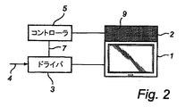
図1に示す照明装置は、ディスプレイユニット1と、1組の追加の発光要素(詳細には示されていない)からなる補助イルミネータ2とを有している。ディスプレイユニットは、例えば、LEDを利用したディスプレイ又はCRTであるのが良く又は能動的に光を放出する他の任意の形式のディスプレイであって良い。補助イルミネータは、LEDのアレイであるのが良く、この補助イルミネータをディスプレイユニットに一体化してもよい。一実施形態によれば、ディスプレイユニット及び補助イルミネータは、同一の大面積LEDアレイの別々の部分で形成される。 The illuminating device shown in FIG. 1 has a display unit 1 and an auxiliary illuminator 2 consisting of a set of additional light emitting elements (not shown in detail). The display unit may be, for example, a display utilizing LEDs or a CRT or any other type of display that actively emits light. The auxiliary illuminator may be an array of LEDs, and the auxiliary illuminator may be integrated into the display unit. According to one embodiment, the display unit and the auxiliary illuminator are formed in separate parts of the same large area LED array.
ディスプレイユニットは、代表的には、カラーディスプレイであり、この場合、イルミネータユニットも又、互いに異なる色、例えば赤色、緑色及び青色の光を放出することができなければならない。好ましくは、イルミネータユニットは、赤色、緑色及び青色のLED9から成るLEDのアレイである。
The display unit is typically a color display, in which case the illuminator unit must also be able to emit light of different colors, for example red, green and blue. Preferably, the illuminator unit is an array of LEDs consisting of red, green and
ディスプレイユニット1は、ディスプレイドライバ3によって制御され、このディスプレイドライバは、ビデオ入力信号4に基づいてビデオ内容を表示させるようディスプレイユニットを動作させる。同一のビデオ信号4は又、補助イルミネータ2からの光出力を制御するよう構成されたコントローラ5に送られる。
The display unit 1 is controlled by a
動作原理を説明すると、コントローラは、イルミネータを制御してイルミネータとディスプレイユニットの両方からの全放出光が所望の周囲光(雰囲気)に一致するよう光を放出させるようになっている。この所望の雰囲気は、変化を生じない固定された値、例えば白色光であるのが良い。変形例として、所望の雰囲気は、経時的に変化するようになっていても良い。雰囲気が経時的にどのように変化するかを定めるタイムプロフィール(時間座標図)は、その原点として、或る恣意的な原点からの時間ではなく、フィルムの開始からの時間を用いるのが良い。いずれの場合においても、所望の雰囲気は、設定値6で表示可能であり、この設定値は、コントローラにあらかじめ記憶されているのが良く(固定された設定値の場合)又は適当なインタフェイス(固定又は漸変設定値)によりコントローラに送られるのが良い。
Explaining the principle of operation, the controller controls the illuminator to emit light so that the total emitted light from both the illuminator and the display unit matches the desired ambient light (atmosphere). The desired atmosphere may be a fixed value that does not change, for example white light. As a modification, the desired atmosphere may change over time. The time profile (time coordinate diagram) that determines how the atmosphere changes over time should use the time from the beginning of the film as the origin, not the time from any arbitrary origin. In any case, the desired atmosphere can be displayed with a
設定値は、所望の色内容並びに所望の強度を表すことができる。設定値は、好ましくは、典型的な三原色系におけるイルミネータユニット3の三原色、例えば赤色、緑色及び青色からの色の寄与率の観点で表される。
The set value can represent the desired color content as well as the desired intensity. The set value is preferably expressed in terms of the contribution ratio of the colors from the three primary colors of the
図1の実施形態では、コントローラ5は、所望の雰囲気及びビデオ入力信号に基づいて相補出力レベルを計算するようになっている。
In the embodiment of FIG. 1, the
図2に示す別の実施形態によれば、フィルム又はビデオシーケンスにはコントローラ5のための制御信号として用いられるようになったあらかじめ計算された相補信号7を提供するのが良い。相補信号7を多重化してビデオストリーム4の状態にし、ドライバ3により図2に示すように分離し又は別個のチャネルを介して送るのが良い。あらかじめ計算された相補信号7を用いることにより、コントローラ5が単純化される。というのは、この場合、コントローラは、光のレベルそれ自体を計算する必要がないからである。ただし、コントローラは、ビデオとの同期性を保持する必要がある。単純な実施形態では、同期化は、一定の単位時間当たり1つの光レベル信号、例えば、xマイクロ秒当たり1つの信号を有することにより行われる。
According to another embodiment shown in FIG. 2, the film or video sequence may be provided with a pre-calculated
図3a〜図3cは、白色周囲光をもたらす単純な場合におけるコントローラによって行われる制御の仕方を示している。図3aは、所与の時点におけるビデオ信号の相補RGBレベルを示している。所望の全出力は、レベル8で示されている。図3bは、ビデオ出力とイルミネータ出力の組合せの結果として、図3cに示すような等しいRGBレベル、即ち白色光が得られるようコントローラによって設定された相補RGBレベルを示している。
Figures 3a to 3c show the manner of control performed by the controller in the simple case that results in white ambient light. FIG. 3a shows the complementary RGB levels of the video signal at a given time. The desired total output is shown at
レベル8は、白色光の所望の強度を示している。このレベルは、ビデオ信号の任意の色に関して最大出力レベルと同じほど低いものであるのが良い。所望の強度8′がこの最大レベルよりも低い場合、フルカラー補正を達成するには、必ず、強度を所望のレベルよりも高くしなければならない。これは、図4a〜図4cに示されている。
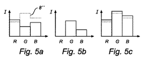
図5a〜図5cは、所望の全出力8″が白色ではない別の状況を示している。この場合、ビデオ信号のRGBレベルのうちの1つ(この場合、赤色レベル)は所望のエネルギーよりも高いことが可能である。このような場合でも、フルカラー補正は、達成するには、図5b及び図5cに示すように所望の強度からの逸脱なしには達成できない。
Figures 5a to 5c show another situation where the desired
フルカラー補正を行うことができない、例えば上述した場合では、強度レベルを超えるのではなく、ビデオ内容を僅かに歪ませるようディスプレイレベルを下方に調整するのが良い。さらに別の代替手段は、所望の値から逸脱した全光出力を許容することである。最後に、幾つかの行為を組み合わせること、例えば、ディスプレイ出力レベルを減少させると同時に所望の強度レベルを超えるようにすることによってかかる逸脱を取り扱うことができる。 For example, in the case described above where full color correction cannot be performed, the display level should be adjusted downward so as not to exceed the intensity level but to slightly distort the video content. Yet another alternative is to allow all light output deviating from the desired value. Finally, such deviations can be handled by combining several actions, for example by reducing the display output level while at the same time exceeding the desired intensity level.
本発明の方法は、設定値が照明及び色の所望のレベルを定めず、最少照明レベルを定めているような場合に利用できる。これは、完全な又はほぼ完全な真っ暗の期間を有していたフィルム又はビデオシーケンスの影響をやわらげる。 The method of the present invention can be used when the set value does not define the desired level of illumination and color, but defines a minimum illumination level. This mitigates the effects of film or video sequences that had a complete or nearly complete dark period.
当業者であれば、本発明は、上述の好ましい実施形態には何ら限定されないことは理解されよう。逆に、特許請求の範囲に記載された本発明の範囲内で多くの改造及び変形が可能である。例えば、1つのディスプレイユニットは、各々が所望の全光出力に互いに異なった寄与率をもたらす複数の補助イルミネータを備えることができる。 One skilled in the art will appreciate that the present invention is not limited to the preferred embodiments described above. On the contrary, many modifications and variations are possible within the scope of the present invention as set forth in the appended claims. For example, one display unit can comprise a plurality of auxiliary illuminators, each providing a different contribution to the desired total light output.
Claims (10)
複数個の追加の発光要素を有するイルミネータユニット(2)と、
前記ビデオ信号(4)及び所望の全光出力を表す設定値(6)に従って前記イルミネータユニット(2)からの追加の光出力を制御するようになったコントローラ(5)とを備え、
前記追加の光出力と組合わされた前記ビデオ出力が、前記所望の全光出力に近似するようになっている、
ことを特徴とする照明装置。 In a lighting device comprising a display unit (1) and a display driver (3) adapted to receive a video signal (4) and control the video output of the display unit based on the video signal,
An illuminator unit (2) having a plurality of additional light emitting elements;
A controller (5) adapted to control an additional light output from the illuminator unit (2) according to the video signal (4) and a set value (6) representing the desired total light output;
The video output combined with the additional light output is adapted to approximate the desired total light output;
A lighting device characterized by that.
請求項1記載の照明装置。 The controller (5) is configured to receive the video signal (4) and calculate a complementary output level based on the video signal and the set value (6).
The lighting device according to claim 1.
請求項1又は2記載の照明装置。 The controller (5) is configured to control the intensity and / or color of the additional light output,
The lighting device according to claim 1.
請求項1ないし3のいずれか1項に記載の照明装置。 The illuminator unit (2) comprises elements (9) that emit different colors.
The lighting device according to any one of claims 1 to 3.
請求項4記載の照明装置。 The illuminator unit (2) comprises at least red, green and blue light emitting elements (9),
The lighting device according to claim 4.
請求項1ないし5のいずれか1項に記載の照明装置。 The set value (6) is variable.
The lighting device according to any one of claims 1 to 5.
請求項1ないし6のいずれか1項に記載の照明装置。 The illuminator unit (2) is formed of an array of LEDs,
The lighting device according to any one of claims 1 to 6.
請求項1ないし7のいずれか1項に記載の照明装置。 The display unit (1) is an array of LEDs,
The lighting device according to any one of claims 1 to 7.
請求項1ないし8のいずれか1項に記載の照明装置。 The display unit (1) and the illuminator unit (2) are formed by only one LED panel.
The lighting device according to any one of claims 1 to 8.
請求項1ないし8のいずれか1項に記載の照明装置。 The display unit (1) is a CRT.
The lighting device according to any one of claims 1 to 8.
Applications Claiming Priority (2)
| Application Number | Priority Date | Filing Date | Title |
|---|---|---|---|
| EP06115190 | 2006-06-09 | ||
| PCT/IB2007/051723 WO2007141674A1 (en) | 2006-06-09 | 2007-05-08 | Illumination device |
Publications (2)
| Publication Number | Publication Date |
|---|---|
| JP2009540494A true JP2009540494A (en) | 2009-11-19 |
| JP2009540494A5 JP2009540494A5 (en) | 2010-06-24 |
Family
ID=38461896
Family Applications (1)
| Application Number | Title | Priority Date | Filing Date |
|---|---|---|---|
| JP2009513802A Abandoned JP2009540494A (en) | 2006-06-09 | 2007-05-08 | Lighting device |
Country Status (9)
| Country | Link |
|---|---|
| US (1) | US20100245673A1 (en) |
| EP (1) | EP2047716B1 (en) |
| JP (1) | JP2009540494A (en) |
| KR (1) | KR20090033215A (en) |
| CN (1) | CN101467489A (en) |
| AT (1) | ATE460825T1 (en) |
| DE (1) | DE602007005263D1 (en) |
| TW (1) | TW200807373A (en) |
| WO (1) | WO2007141674A1 (en) |
Families Citing this family (3)
| Publication number | Priority date | Publication date | Assignee | Title |
|---|---|---|---|---|
| JP5266559B2 (en) * | 2006-10-24 | 2013-08-21 | ティーピー ビジョン ホールディング ビー ヴィ | System, method and computer readable medium for displaying light radiation |
| DK2829161T3 (en) | 2012-03-19 | 2023-04-03 | Brainlit Ab | IMPROVED LIGHTING CONTROL SYSTEM |
| US11083060B2 (en) * | 2018-11-30 | 2021-08-03 | Seoul Semiconductor Co., Ltd. | Lighting apparatus and lighting system including the same |
Family Cites Families (6)
| Publication number | Priority date | Publication date | Assignee | Title |
|---|---|---|---|---|
| DE4207417A1 (en) * | 1992-03-09 | 1993-09-16 | Klemens Amsbeck | TV lounge lighting control device - uses smoothed and compared chrominance signal components for adjustment of dimmers applied to corresp. primary coloured lamps |
| DE10031303A1 (en) * | 2000-06-27 | 2002-01-10 | Arnold & Richter Kg | Lighting device with light emitting diodes (LED), lighting method and method for image recording with such an LED lighting device |
| GB0211898D0 (en) * | 2002-05-23 | 2002-07-03 | Koninkl Philips Electronics Nv | Controlling ambient light |
| KR101021077B1 (en) * | 2002-07-04 | 2011-03-14 | 코닌클리케 필립스 일렉트로닉스 엔.브이. | Method of and system for controlling an ambient light and lighting unit |
| TWI229764B (en) * | 2003-05-14 | 2005-03-21 | Au Optronics Corp | A transflective liquid crystal display device |
| EP1763700A1 (en) * | 2004-06-30 | 2007-03-21 | Koninklijke Philips Electronics N.V. | Active frame system for ambient lighting using a video display as a signal s0urce |
-
2007
- 2007-05-08 US US12/301,852 patent/US20100245673A1/en not_active Abandoned
- 2007-05-08 DE DE602007005263T patent/DE602007005263D1/en active Active
- 2007-05-08 JP JP2009513802A patent/JP2009540494A/en not_active Abandoned
- 2007-05-08 EP EP07735806A patent/EP2047716B1/en not_active Not-in-force
- 2007-05-08 KR KR1020097000362A patent/KR20090033215A/en not_active Application Discontinuation
- 2007-05-08 AT AT07735806T patent/ATE460825T1/en not_active IP Right Cessation
- 2007-05-08 CN CNA2007800214193A patent/CN101467489A/en active Pending
- 2007-05-08 WO PCT/IB2007/051723 patent/WO2007141674A1/en active Application Filing
- 2007-06-06 TW TW096120345A patent/TW200807373A/en unknown
Also Published As
| Publication number | Publication date |
|---|---|
| DE602007005263D1 (en) | 2010-04-22 |
| EP2047716A1 (en) | 2009-04-15 |
| KR20090033215A (en) | 2009-04-01 |
| TW200807373A (en) | 2008-02-01 |
| ATE460825T1 (en) | 2010-03-15 |
| US20100245673A1 (en) | 2010-09-30 |
| WO2007141674A1 (en) | 2007-12-13 |
| CN101467489A (en) | 2009-06-24 |
| EP2047716B1 (en) | 2010-03-10 |
Similar Documents
| Publication | Publication Date | Title |
|---|---|---|
| US7766489B2 (en) | Device for projecting a pixelated lighting pattern | |
| CN100353219C (en) | Illuminator, projection display device and method for driving the same | |
| KR101468901B1 (en) | System and method for creating artificial atmosphere | |
| EP2135490B1 (en) | Method of controlling the lighting of a room in accordance with an image projected onto a projection surface | |
| WO2010024000A1 (en) | Image display device and image display device drive method | |
| TW200705987A (en) | Display device | |
| JP2007018013A5 (en) | ||
| JP2013514620A (en) | Ambience lighting system using global content characteristics | |
| JP2013513830A (en) | Powerful ambience lighting system | |
| TW200605019A (en) | Method and apparatus for power level control and/or contrast control in a display device | |
| TW200623010A (en) | Image display apparatus | |
| JP2008541141A5 (en) | ||
| JP2008541141A (en) | LIGHT SOURCE DEVICE AND DISPLAY DEVICE FOR BACKLIGHTING (BACK LIGHTING) OF DISPLAY DEVICE | |
| US10491868B2 (en) | Projection video display apparatus | |
| JP2008277092A (en) | Luminaire | |
| KR20170018783A (en) | Stage Representation System and Stage Representation Method | |
| CN101529984B (en) | A system, method and computer-readable medium for displaying light radiation | |
| WO2009153852A1 (en) | Lighting apparatus for display, and display unit | |
| JP2007140234A (en) | Image display device, liquid crystal display device and audio vidual environment control system | |
| JP2009540494A (en) | Lighting device | |
| JP5376751B2 (en) | projector | |
| TWI503810B (en) | Oled lighting module and lighting apparatus and interactive light wall using the same | |
| WO2022009789A1 (en) | Self-emissive element panel, led panel, and planetarium using same | |
| US11029008B2 (en) | Lighting fixture including a color changing component | |
| JP7398648B2 (en) | Projector and projector control method |
Legal Events
| Date | Code | Title | Description |
|---|---|---|---|
| A521 | Request for written amendment filed |
Free format text: JAPANESE INTERMEDIATE CODE: A523 Effective date: 20100507 |
|
| A621 | Written request for application examination |
Free format text: JAPANESE INTERMEDIATE CODE: A621 Effective date: 20100507 |
|
| A762 | Written abandonment of application |
Free format text: JAPANESE INTERMEDIATE CODE: A762 Effective date: 20100604 |