JP2009536282A - Lobe-type exhaust diffuser device, system, and method - Google Patents
Lobe-type exhaust diffuser device, system, and method Download PDFInfo
- Publication number
- JP2009536282A JP2009536282A JP2008550561A JP2008550561A JP2009536282A JP 2009536282 A JP2009536282 A JP 2009536282A JP 2008550561 A JP2008550561 A JP 2008550561A JP 2008550561 A JP2008550561 A JP 2008550561A JP 2009536282 A JP2009536282 A JP 2009536282A
- Authority
- JP
- Japan
- Prior art keywords
- exhaust gas
- exhaust
- distal end
- lobe
- lobes
- Prior art date
- Legal status (The legal status is an assumption and is not a legal conclusion. Google has not performed a legal analysis and makes no representation as to the accuracy of the status listed.)
- Pending
Links
Images


Classifications
-
- F—MECHANICAL ENGINEERING; LIGHTING; HEATING; WEAPONS; BLASTING
- F01—MACHINES OR ENGINES IN GENERAL; ENGINE PLANTS IN GENERAL; STEAM ENGINES
- F01N—GAS-FLOW SILENCERS OR EXHAUST APPARATUS FOR MACHINES OR ENGINES IN GENERAL; GAS-FLOW SILENCERS OR EXHAUST APPARATUS FOR INTERNAL-COMBUSTION ENGINES
- F01N3/00—Exhaust or silencing apparatus having means for purifying, rendering innocuous, or otherwise treating exhaust
- F01N3/02—Exhaust or silencing apparatus having means for purifying, rendering innocuous, or otherwise treating exhaust for cooling, or for removing solid constituents of, exhaust
- F01N3/021—Exhaust or silencing apparatus having means for purifying, rendering innocuous, or otherwise treating exhaust for cooling, or for removing solid constituents of, exhaust by means of filters
-
- F—MECHANICAL ENGINEERING; LIGHTING; HEATING; WEAPONS; BLASTING
- F01—MACHINES OR ENGINES IN GENERAL; ENGINE PLANTS IN GENERAL; STEAM ENGINES
- F01N—GAS-FLOW SILENCERS OR EXHAUST APPARATUS FOR MACHINES OR ENGINES IN GENERAL; GAS-FLOW SILENCERS OR EXHAUST APPARATUS FOR INTERNAL-COMBUSTION ENGINES
- F01N13/00—Exhaust or silencing apparatus characterised by constructional features
- F01N13/08—Other arrangements or adaptations of exhaust conduits
- F01N13/082—Other arrangements or adaptations of exhaust conduits of tailpipe, e.g. with means for mixing air with exhaust for exhaust cooling, dilution or evacuation
-
- F—MECHANICAL ENGINEERING; LIGHTING; HEATING; WEAPONS; BLASTING
- F01—MACHINES OR ENGINES IN GENERAL; ENGINE PLANTS IN GENERAL; STEAM ENGINES
- F01N—GAS-FLOW SILENCERS OR EXHAUST APPARATUS FOR MACHINES OR ENGINES IN GENERAL; GAS-FLOW SILENCERS OR EXHAUST APPARATUS FOR INTERNAL-COMBUSTION ENGINES
- F01N13/00—Exhaust or silencing apparatus characterised by constructional features
- F01N13/20—Exhaust or silencing apparatus characterised by constructional features having flared outlets, e.g. of fish-tail shape
-
- Y—GENERAL TAGGING OF NEW TECHNOLOGICAL DEVELOPMENTS; GENERAL TAGGING OF CROSS-SECTIONAL TECHNOLOGIES SPANNING OVER SEVERAL SECTIONS OF THE IPC; TECHNICAL SUBJECTS COVERED BY FORMER USPC CROSS-REFERENCE ART COLLECTIONS [XRACs] AND DIGESTS
- Y02—TECHNOLOGIES OR APPLICATIONS FOR MITIGATION OR ADAPTATION AGAINST CLIMATE CHANGE
- Y02T—CLIMATE CHANGE MITIGATION TECHNOLOGIES RELATED TO TRANSPORTATION
- Y02T10/00—Road transport of goods or passengers
- Y02T10/10—Internal combustion engine [ICE] based vehicles
- Y02T10/12—Improving ICE efficiencies
Landscapes
- Engineering & Computer Science (AREA)
- Chemical & Material Sciences (AREA)
- Combustion & Propulsion (AREA)
- Mechanical Engineering (AREA)
- General Engineering & Computer Science (AREA)
- Exhaust Silencers (AREA)
- Exhaust Gas After Treatment (AREA)
Abstract
内燃機関からの排気ガスを冷却するように構成されたローブ型排気ディフューザ装置、システム、及びその方法は、エンジンからの排気ガスを受けるよう構成された近位端部(215)と、排気ガスを大気中へ放出するよう構成されている遠位端部(205)とを有するディフューザ(200)を具える。複数のローブ(225)は、排気ガスの少なくとも一部がローブ(225)を通過するように遠位端部(205)に配置され、排気ガスと大気の間の交わる面積を大きくし、排気ガスと大気気体の間のさらなる急速な拡散と吸い込みとともに、結果的に排気ガスをさらに急速に冷却する。
【選択図】 図2AA lobe-type exhaust diffuser apparatus, system, and method configured to cool exhaust gas from an internal combustion engine includes a proximal end (215) configured to receive exhaust gas from the engine, and an exhaust gas A diffuser (200) having a distal end (205) configured to be released into the atmosphere. The plurality of lobes (225) are disposed at the distal end (205) such that at least a portion of the exhaust gas passes through the lobe (225), increasing the intersecting area between the exhaust gas and the atmosphere, and exhaust gas. As a result, the exhaust gas is cooled more rapidly, with more rapid diffusion and suction between the gas and the atmospheric gas.
[Selection] Figure 2A
Description
本発明は排気システムに関するものであり、特に、封入された排気流動が出るときの排気ガスを冷却するための装置、システム、及びその方法に関する。 The present invention relates to an exhaust system, and more particularly to an apparatus, system, and method for cooling exhaust gas when an enclosed exhaust flow exits.
本特許出願は、ここに全体を組み込んでいる代理人整理番号1900.2.15及び依頼人整理番号8−02−4819の本出願と同日に出願された出願シリアルナンバ<シリアルナンバ>標題「Enclosed Volume Exhaust Diffuser Apparatus, System, and Method」の出願に関連するものである。 This patent application is filed on the same day as the present application of Attorney Docket No. 1900.2.15 and Client Docket No. 8-02-4819, which is incorporated herein in its entirety. The title “Enclosed” Volume Exhaust Diffuser Apparatus, System, and Method ".
窒素酸化物(NOx)や特定の物質などエンジン排気ガスに関する環境規制は、ますます厳しくなっている。米国において米国環境保護庁は、ディーゼルエンジン粒子状物質に関し、新しくさらに厳しい環境規制を2007年に始め、排気を大気中へ流入させる前の排気流動中に配設されたNOx吸収材などディーゼル粒子フィルタおよび/または他の排気処理装置が必要とされるようになる。 Environmental regulations regarding engine exhaust gases such as nitrogen oxides (NOx) and certain substances are becoming stricter. In the United States, the US Environmental Protection Agency has started new and stricter environmental regulations in 2007 regarding diesel engine particulate matter, and diesel particulate filters such as NOx absorbers installed in the exhaust flow before the exhaust flows into the atmosphere. And / or other exhaust treatment devices are required.
ほとんどの場合、排気処理システムは、装置に煤やNOx、同様のものが充満すると、粒子フィルタやNOx吸収材、他の排気処理装置の再生を適宜開始しなければならない。一例として、粒子フィルタの場合、再生は、フィルタの温度を煤が酸化される400C以上まで上げて、フィルタの大きさやフィルタ上の煤の量、煤の均一性の程度などを含む環境に依存して何分間かそれ以上の間、温度を維持することによってなされる。 In most cases, the exhaust treatment system must initiate regeneration of the particulate filter, NOx absorbent, and other exhaust treatment devices as appropriate once the device is full of soot, NOx, and the like. As an example, in the case of a particle filter, regeneration depends on the environment, including the filter size, the amount of soot on the filter, the degree of soot uniformity, etc., raising the temperature of the filter to over 400C where the soot is oxidized. This is done by maintaining the temperature for several minutes or longer.
この種の再生はフィルタ温度を高くすることを必要とするものであり、具体的には、排気の温度は静止又は低速運転状態で上昇するので、排気は通常運転中よりもさらに高い温度で自動車の排気管を出る。これは、排気管から出るガスの熱流束に関する潜在的な安全上の問題につながるものであり、近くにいる人や動物、植物を不快にさせるか傷を負わせてしまう。また、排気系部品の表面温度も上昇させてしまう。 This type of regeneration requires a higher filter temperature. Specifically, the exhaust temperature rises at rest or at low speeds, so the exhaust is at a higher temperature than during normal operation. Exit the exhaust pipe. This leads to a potential safety problem with the heat flux of the gas exiting the exhaust pipe, which can make nearby people, animals and plants uncomfortable or injured. Further, the surface temperature of the exhaust system parts is also increased.
この問題に対処する一つの方法として、高温の排気ガスを放出するようにエンジンや排気処理システムが配設されている自動車や機械においてその操作者に警告を発し、操作者が状況を緩和する手段、例えば、感応対象から装置を離すように動かして冷却処置を開始させるなどのステップを潜在的に具える手段などをとる方法がある。しかしながら、これは操作者が介在することを必要とする精密で高価なセンサや調整装置を必要とするものであり、どんな場合にも操作者の緩和選択手段は比較的制限されうる。可能であれば危険な温度に達することのないように、排気管から出る前か出るときに、第1の場所で排気ガスが連続的に冷却されることが好ましい。 One way to deal with this problem is to alert the operator in an automobile or machine where an engine or exhaust treatment system is arranged to emit hot exhaust gas, and the operator can relax the situation. For example, there is a method of taking a means that potentially includes a step of moving a device away from a sensitive object to start a cooling treatment. However, this requires precise and expensive sensors and adjustment devices that require the operator to intervene, and in any case the operator's mitigation selection means can be relatively limited. It is preferred that the exhaust gas is continuously cooled at the first location before or when leaving the exhaust pipe so that dangerous temperatures are not reached if possible.
有害な結果を緩和するための排気の処理は、:音を低減するために以前から在るマフラーや共振フィルタ、及び触媒フィルタ、粒子フィルタや排出物質を調整するために開発されてきたようなものなど、もちろん新しいものではない。しかしながら、排気が大気へ流入する際の熱の低減という一般的問題は、新しいアプローチを必要とする比較的新しい問題である。この問題は、消防車が水を汲み上げるときのこの排気温度の低減など一定の制限的な状況において処理されてきた。一部の(全てではない)消防車は、排気を冷却するために排出口に散水器を具えているが、このような機構は既存の水道があって、このような状況において経験不足の単独の機械の操作者ではなく熟練の消防士がホースを手で持つ状況に制限される。 Exhaust treatment to mitigate harmful consequences: such as those that have been developed to adjust existing mufflers and resonant filters, and catalytic filters, particle filters and emissions to reduce sound Of course, it is not new. However, the general problem of reducing heat as the exhaust enters the atmosphere is a relatively new problem that requires a new approach. This problem has been addressed in certain restrictive situations, such as reducing the exhaust temperature when a fire engine pumps water. Some (but not all) fire trucks have sprinklers at the outlets to cool the exhaust, but such mechanisms have existing waterworks and are inexperienced alone in such situations. Skilled firefighters, not operators of other machines, are limited to having a hose in their hands.
前述のことから、エンジン駆動機械、特にディーゼルエンジンを具えるエンジン駆動機械の排気管から排気ガスが出る場合には、これらを冷却し、再生を必要とする粒子フィルタや他の処理装置が必要とされることは明らかである。上述の排出物の調整装置を使用していないある種の職業の自動車も冷却された排気ガスから利益を受けることができる。 From the above, when exhaust gas is discharged from the exhaust pipe of an engine drive machine, particularly an engine drive machine including a diesel engine, it is necessary to cool the particles and to have a particle filter or other processing device that needs to be regenerated. Obviously it will be done. Certain occupational vehicles that do not use the above-described emission control devices can also benefit from cooled exhaust gas.
本発明は、現在の技術、特に最近利用可能なシステムによって十分に解決されていない技術における問題と必要性に対応するために開発された。従って、本発明は、技術的な多くの又はすべての問題を克服するため、排気ガスを冷却する装置、システム、及び方法を提供するように開発された。 The present invention has been developed to address problems and needs in current technology, particularly technology that has not been adequately solved by recently available systems. Accordingly, the present invention has been developed to provide an apparatus, system, and method for cooling exhaust gas to overcome many or all technical problems.
本発明の一態様において、内燃機関からの排気ガスを冷却する装置は、近位端部と、遠位端部とを有するディフューザを具える。前記近位端部は前記機関から排気ガスを受けるよう構成され、前記遠位端部は、前記排気ガスを大気中へ放出するよう構成されている。複数のローブは、前記遠位端部に少なくとも部分的に配置されており、このローブは、前記排気ガスの少なくとも一部がこのローブを通過するように構成されている。一実施例では、前記遠位端部の円周が前記近位端部の円周より大きく、前記遠位端部の断面積は前記近位端部の断面積とほぼ同じである。 In one aspect of the invention, an apparatus for cooling exhaust gas from an internal combustion engine includes a diffuser having a proximal end and a distal end. The proximal end is configured to receive exhaust gas from the engine and the distal end is configured to release the exhaust gas into the atmosphere. A plurality of lobes are at least partially disposed at the distal end, and the lobes are configured such that at least a portion of the exhaust gas passes through the lobes. In one embodiment, the circumference of the distal end is greater than the circumference of the proximal end, and the cross-sectional area of the distal end is substantially the same as the cross-sectional area of the proximal end.
さらなる実施例では、ブロックがローブ内に設けられ、前記ブロックは、通路から前記ローブの間の前記中央空間を通る前記排気ガスを少なくとも部分的に止めるように構成されている。 In a further embodiment, a block is provided in the lobe, the block being configured to at least partially stop the exhaust gas passing from the passage through the central space between the lobes.
本発明のさらなる態様では、排気ガスを冷却する方法が、前記排気ガスを第1通路を通して押し進めるステップと、前記排気ガスを複数のローブを通して押し進めるステップと、前記排気ガスを前記ローブから大気中へ放出するステップとを具える。一実施例では、前記排気ガスの流れがほぼ均一になるように、前記排気ガスの前記ローブのほぼ全体の内側面に近接した部分を前記ローブを通して押し進める。 In a further aspect of the invention, a method of cooling exhaust gas includes pushing the exhaust gas through a first passage, pushing the exhaust gas through a plurality of lobes, and releasing the exhaust gas from the lobe into the atmosphere. And a step to perform. In one embodiment, a portion of the exhaust gas proximate to the entire inner surface of the lobe is pushed through the lobe so that the exhaust gas flow is substantially uniform.
本発明のさらなる態様では、ディーゼルエンジンの排気処理及び冷却システムが、前記エンジンで生成される排気ガスをほぼ収容して方向付ける排気パイプと、前記排気パイプに配設される排気処理機構とを具える。排気処理機構は、前記排気ガスの組成を改良するよう構成される。前記排気処理機構に機能的に取り付けられた再生機構は、前記排気処理機構を適宜再生するよう構成される。前記排気処理機構のハウジングのダウンストリームに配設された冷却機構は、複数のローブを具え、前記排気ガスを前記排気パイプから受けて、前記排気ガスを大気へ放出するよう構成される。 In a further aspect of the invention, an exhaust treatment and cooling system for a diesel engine comprises an exhaust pipe that substantially accommodates and directs exhaust gas produced by the engine, and an exhaust treatment mechanism disposed in the exhaust pipe. Yeah. The exhaust treatment mechanism is configured to improve the composition of the exhaust gas. A regeneration mechanism operatively attached to the exhaust treatment mechanism is configured to regenerate the exhaust treatment mechanism as appropriate. A cooling mechanism disposed downstream of the housing of the exhaust treatment mechanism includes a plurality of lobes, configured to receive the exhaust gas from the exhaust pipe and to release the exhaust gas to the atmosphere.
この明細書の特性、利点、又は同様の言葉への言及は、本発明によって実現しうる全ての特性や利点を示唆するものではなく、全ての特性や利点は本発明の様々な一の実施例においてなされるものである。むしろ、この特性や利点について言及した言葉は、本発明の少なくとも一実施例に含まれる一実施例と結びついた特定の特性や利点、特徴を意味するものとして理解されるべきである。この明細書中の特性や利点、同様の言葉の記述は、必ずしも同じ実施例を言及する必要はない。 References to features, advantages, or similar terms in this specification do not imply all features or advantages that may be realized by the present invention, and all features and advantages are not intended to be considered as various embodiments of the present invention. It is made in. Rather, words referring to these characteristics and advantages are to be understood as meaning the specific characteristics, advantages and features associated with one embodiment included in at least one embodiment of the invention. Features, advantages, and similar language descriptions in this specification need not necessarily refer to the same embodiment.
記述した本発明の特性、利点、及び特徴は、1又はそれ以上の実施例における様々な好適な手段と組み合わせてもよい。関連技術の当業者は、特定の実施例の1又はそれ以上の一定の特性や利点なく本発明を実施してもよいと理解することができる。他の例では、全ての実施例に存在しないさらなる特性や利点が、本発明の一定の実施例において認められてもよい。本発明のこれらの特性及び利点は、以下の記述や添付した請求の範囲からさらに十分に明らかになるか、説明された本発明を実施することによって確認されてもよい。 The described characteristics, advantages and features of the invention may be combined with various suitable means in one or more embodiments. One of ordinary skill in the relevant art can appreciate that the invention may be practiced without one or more of the specific features or advantages of a particular embodiment. In other instances, additional features and advantages not found in all embodiments may be recognized in certain embodiments of the invention. These features and advantages of the present invention will become more fully apparent from the following description and appended claims, or may be learned by practice of the described invention.
本発明の利点を理解しやすくするために、本発明は、添付した図面に示した特定の実施例を参照することによって具体的に説明されており、これは本発明の一般的な実施例のみを示すものであり、本発明の範囲を限定するものではない。 In order to facilitate understanding of the advantages of the present invention, the present invention has been specifically described by reference to specific embodiments illustrated in the accompanying drawings, which are only general embodiments of the present invention. Is not intended to limit the scope of the present invention.
この明細書中の「一実施例(one embodiment)」、「ある実施例(an embodiment)」、又は同様の言葉を通した言及は、本発明の少なくとも一の実施例に含まれる実施例に関連する特定の特性、構造、又は特徴を意味する。この明細書中の「一実施例において(in one embodiment)」、「ある実施例において(in an embodiment)」、又は同様の言葉は、同じ実施例を全て言及する必要はない。 References throughout this specification to "one embodiment", "an embodiment", or similar language relate to embodiments included in at least one embodiment of the invention. Meaning a particular property, structure, or feature. In this specification, “in one embodiment”, “in an embodiment”, or similar language need not refer to all of the same embodiments.
記述した本発明の特性、利点、及び特徴は、1又はそれ以上の実施例における様々な好適な手段と組み合わせてもよい。以下に、数多くの具体的な詳細を本発明の実施例の理解のために提供する。しかしながら、関連技術の当業者は、本発明を1又はそれ以上の特定の細部なく、又は他の方法、構成部品、物質、その他によって実施しうる。他の例としての公知の構造や、物質、操作についての詳細は、本発明の態様を不明瞭にすることを避けるため記述していない。 The described characteristics, advantages and features of the invention may be combined with various suitable means in one or more embodiments. In the following, numerous specific details are provided for an understanding of embodiments of the invention. However, one of ordinary skill in the relevant art may implement the invention without one or more specific details or by other methods, components, materials, etc. Details of other known structures, materials, and operations are not described in order to avoid obscuring aspects of the invention.
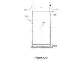
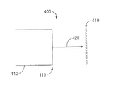
図1は、従来技術の円筒形の排気ガス排気管110を示す。排気管110は、既知の連結具105を介して排気パイプ又は他の排気系部品(例えば、マフラー)に取り付けられるか、代替的に排気系部品を具える簡単な単一構造にしてもよい。排気ガスは、矢印110の方向に排気管110を通過し、排気管110の遠位端部115で大気へ流入する。
FIG. 1 shows a prior art cylindrical exhaust
動作中、排気管110に機能的に連結されたエンジンから放出された排気ガスは、排気パイプ、排気処理装置、又は他の排気系部品もしくは通路から排気管110へ入り、大気中に放出される。排気ガスは、ほぼ円筒形(排気管110の形)で大気へ流入して拡散し、これらは冷たい大気気体と相互作用するときに冷却される。
During operation, exhaust gas emitted from an engine operatively connected to the
排気ガスは、排気管110から離れるように動いて遅くなり、大気気体によって薄められる。また、大気気体は、排気ガス中へほぼ矢印方向130に吸い込まれる。大気気体の吸い込みは、上述のように、円筒形状の、特に排気管110の遠位端部115近くで流れの速い排気ガスと通常遅い大気気体とが交わる部分で起こる。吸い込みが起こるためには、大気気体が排気ガスとほぼ同じ運動量を得なければならない。
The exhaust gas moves away from the
排気ガスは、移動して遠位端部115から離れるほど、大気気体によってますます薄められ遅くなるので、排気流が大気気体へますます取り込まれやすくなり、排気管110から少し離れた場所までに、排気ガスは完全に薄められて大気中へ拡散される。
As the exhaust gas moves away from the
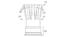
図2A乃至2Cは、本発明による排気ガスディフューザ200の一実施例を示し、図2Bは、ディフューザの遠位端部のみを示し、他の詳細は説明を明確にするために省略している。ディフューザ200は出口又は遠位端部205を具え、排気ガスは、図2Cの矢印210が示すように大気へ入る。ディフューザ200の近位端部215は、排気系の台と単一形にしてもよく、公知の連結具105に使用した構造及び方法と同じように排気パイプに連結具220を介して取り付けるか、所望されるように及び特定の機械に決定される環境や構造の通りに、排気処理装置に直接取り付けてもよい。作動時に同じ結果を得られるように、ディフューザ200は、既存の排気管に連結されて排気管から伸びているか、排気系の台と一緒に構成されて、ディフューザ200自体を独自の排気管にするようにしてもよい。
2A-2C show one embodiment of an
ディフューザ200の遠位端部205には溝が付けられており、一連のローブ225を形成しており、内部空間227周りに環状に集合的に配置されている。ローブ225は、近位端部215から遠位端部205へ延在し、遠位端部に近くなるほど断面が大きくなり、近位端部215から遠位端部205へローブの軸方向又は縦方向にテーパ形が大きくなる。
The
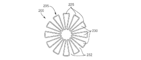
ローブ225は、ローブ225の間に位置する中間部分232でそれぞれ容積230を規定する。ここに使用する「ローブ(Lobe)」は、ディフューザの遠位端部205に位置する突出部又は区画を意味し、ローブは、近位端部215によって規定される排気路の突出部又は区画である。ローブは、様々な種類や大きさ、形にすることができ、それらのいくつかを以下の図6乃至12に示した。ローブは、互いに連結しているか、連結していなくてもよいが、どんな場合も、互いに少なくとも部分的に間隔を空けて配置されている。一実施例では、ローブ容積230の断面は、図2Cに示すように断面の上端部230aと、断面の側部230b及び230cから成る三角形である。側部230bは、上端部225aから垂直に延在している垂直線235から角度αを成している。角度αは、一実施例では20度である。ローブ225のこの構造において、内部空間227は截頭円錐形である。中間部分232はローブ容積230と同じ形である。
The
また、ローブ225は、図2Bに最も明瞭に示すように、ディフューザ200の半径方向の中心からディフューザ200の半径方向外側縁部へテーパ形となっている。
Also, the
一実施例では、ディフューザ200は、12(12)個のローブ225を具え、それぞれは、近位端部215から遠位端部205へ軸方向にほぼ4インチ延在する。遠位端部205がほぼ6インチ径のとき、近位端部215はほぼ4乃至5インチ径である。他の寸法や構成も可能であり、その一部を以下に示すが、これに限定する意図ではない。例えば、ローブ225は、形状や幅を改良して、軸方向に長いか半径方向に太くしてもよい。図2に示す特定の実施例では、側部230bの角度は、ローブ225を通る排気ガスの流れが比較的一様に均質であるようほぼ20度に制限される。図2に示された実施例の特定の幾何学形状によって得られるさらに大きい角度は、排気ガスをローブ容積230の側部230bからさらに離れるように引き出し、ガスの流動中に流れを妨げる渦をさらに作り出す。他の構成、寸法、及び実施例にすることによって、最適に実施するためには異なる条件が必要となる。
In one embodiment, the
一実施例では、例えば、ローブ225を含む(中間部分232を含まない)遠位端部205の集合断面積は、近位端部215の断面積とほぼ同じである。この実施例において、ディフューザ200の特定の幾何学形状及び寸法が得られ、遠位端部205の面積が近位端部215の面積より著しく小さい場合、排気ガスは大きい速度で噴出して遠位端部205から離れ、排気ガス中へ大気気体が吸い込まれることはより難しくなる。近位端部215より大きい断面積の遠位端部205を具える他の構成も可能であり、最適に実施するためには異なる条件が必要となる。
In one embodiment, for example, the collective cross-sectional area of the
ディフューザは、特定のアプリケーションに必要とされるステンレス鋼や、鋼又はアルミニウム被覆鋼など他の材料から作ることもできる。 The diffuser can also be made from other materials such as stainless steel or steel or aluminized steel as required for a particular application.
ディフューザは、1又はそれ以上の排気処理機構や流体吸引装置(既知の技術)、他の装置による排気系の前に配設されてもよく、ここへ直接連結されるかこのような装置から様々な長さのパイプによって離れて配置されてもよい。 The diffuser may be disposed in front of one or more exhaust treatment mechanisms, fluid suction devices (known techniques), exhaust systems by other devices, directly connected thereto, or various from such devices May be spaced apart by long pipes.
作動中に、ディフューザ200に機能的に連結されたエンジンから放出された排気ガスは、排気パイプや、排気処理装置、他の排気系部品もしくは通路からディフューザ200へ入り、大気中へ放出される。しかしながら、図1のように円筒形で大気へ入るよりも、ディフューザ200を通って流れる排気ガスは、図2Bに示される溝付の形状の遠位端部205で大気中へ流入して、拡散し、これらは冷たい大気気体と相互作用するときに冷却される。
During operation, exhaust gas emitted from an engine operatively connected to the
図1と2とを比較すると、遠位端部115の排気管110の円周は、排気流動の形状を規定し、遠位端部205のディフューザ200の円周よりかなり小さいことが分かる(「円周」は、必ずしも円であることを意味するのではなく、遠位端部での排気ガスと大気気体との交わる部分の実際の輪郭線であり、この場合は、花に似た形状である)。遠位端部205の円周が遠位端部115よりも著しく大きいことによって、排気ガスと大気が交わる面積はより大きくなる、すなわち、排気ガスは大気中へさらに効率的に吸い込まれ拡散する。
Comparing FIGS. 1 and 2, it can be seen that the circumference of the
図1の円筒形状の排気ガス中への大気気体吸い込みが非効率的である代わりに、ディフューザ200は、図2Cの矢印240に示されるように、大気気体を中間部分232へ入らせることで、排気ガスのさらなる急速な吸い込み、拡散とともに結果的に冷却を提供する。
Instead of the inefficiency of atmospheric gas ingestion into the cylindrical exhaust gas of FIG. 1, the
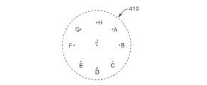
図3A及び3Bは、排気管110及びディフューザ200からの排気ガスの温度を測定するための測定装置400を示す。図示するように、測定の際には、排気管110を、遠位端部115が熱電対配列410に面するように配置し、配列410は、排気の流れの障害となることを最小限にしつつ温度を測定するように排気流動中の様々な位置に配置された熱電対を有し、ディスク形状パターンに並べた。配列410は、排気管110からの排気ガスの流れの軸(矢印420で示す)に対して垂直方向に、遠位端部115から6インチの所に配置された。排気ガスの温度は、配列410の9つの熱電対測定点で測定された。点Jは、排気の流れの中央であり、点A乃至Hは、点J周りに環状に配置されており、それぞれ点Jから半径方向に3.5インチ離れている。
3A and 3B show a
測定は、遠位端部115の上流に約48インチのコージライトセラミック粒子フィルタを使用した普通のディーゼルトラックを用いて、フィルタの再生温度が1022°Fかそれ以上に達した状態で、粒子フィルタが定常再生している間行われた。周囲の環境は、曇りで温度75乃至85Fの微風であった。
Measurements were made using a conventional diesel truck using a about 48 inch cordierite ceramic particle filter upstream of the
測定装置は、遠位端部205を有するディフューザ200が遠位端部115を有する排気管110の代わりに用いられていること以外、同じ条件・同じ方法及び装置のディフューザ200に対しても実行された。
The measuring device is also implemented for a
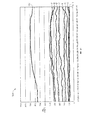
排気管110を使用した約300秒間の測定結果を図4のグラフ400に示し、時間の関数として温度を示す。ラインDEは、遠位端部115で測定された排気の流れの温度を表している。他のラインA乃至H、及びJは、熱電対配列410に対応した測定点で測定された排気ガスの温度を示す。
The measurement results for about 300 seconds using the
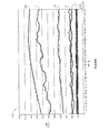
ディフューザ200を使用した約300秒間の測定結果を図5のグラフ400に示し、時間の関数として温度を示す。ラインDEは、遠位端部205で測定された排気の流れの温度を表している。他のラインA乃至H、及びJは、熱電対配列410に対応した測定点で測定された排気ガスの温度を示す。配列410の点Jである排気流動の半径方向の中心の温度は、ディフューザ200を使用している方がかなり低く、大気気体の排気ガス中への吸い込みがよりよく行われ、排気ガスの大気中への拡散がよりよく行われていることを示している。
The measurement results for about 300 seconds using the
図6乃至11は、本発明による溝付の排気管又はディフューザの他の実施例を示しており、全ての図面は装置の遠位端部を示し、他の詳細は説明を簡単にするために省略している。図示した実施例は、エンジンの排気ガスを大気気体に直接拡散するために使用されることを意図している。 6-11 show another embodiment of a slotted exhaust pipe or diffuser according to the present invention, all drawings showing the distal end of the device, and other details for ease of explanation. Omitted. The illustrated embodiment is intended to be used to diffuse engine exhaust gases directly into atmospheric gases.
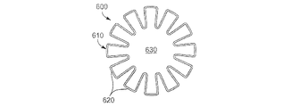
図6では、本発明によるディフューザ600の遠位端部610に溝が付けられており、結果的にローブ225とローブ620は、これらがローブ225よりも半径方向に内方へ小さく延在して、内部空間630がより大きくなっていることを除いて構造は同じである。
In FIG. 6, the
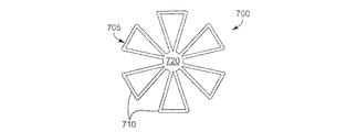
図7では、本発明によるとディフューザ700の遠位端部705は、6個のローブ710を具えており、内部空間はなく、それぞれのローブ710は、全てのローブ710が連結している部分720へ半径方向に内方にテーパ形である。ディフューザ700の遠位端部705は、互いに分離した複数の個別のローブを具えているので、単一の溝付の出口ではないが(単一の溝付の出口とは異なり、ローブは全て、同じ出口の一部分である)、遠位端部705の円周及び排気ガスと大気との交わる部分が大きくなる場合も本発明の範囲内にあり、吸い込みが改良される。
In FIG. 7, according to the present invention, the
図8では、本発明によるディフューザ800の遠位端部805は、外側の半径方向の面820が四角ではなく丸みのある10個のローブ810を具える。丸みの付いた外側の半径方向の面820は、排気流動をよりよく流し渦を少なくするための一部の構成において望ましい。
In FIG. 8, the
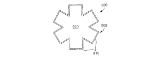
図9では、本発明によるディフューザ900の遠位端部905は、6個のテーパ形ではない四角のローブ910を具え、大きな内部空間920を有する。
In FIG. 9, the
図10では、本発明によるディフューザ1000の遠位端部1010は、ほぼ長円形であり、ローブ1020を形成するように溝が付けられている。図10に例示するように、本発明によるディフューザや排気管の基本形状は、円形、長円形、四角形、又は本発明の範囲内にある他の形状である。
In FIG. 10, the
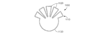
図11では、本発明によるディフューザ1100の遠位端部1110は、ローブ225とほぼ同じ形状の5個のローブ1120を具え、主な相違点は、ローブ1120が遠位端部1110の円周に部分的にのみ延在し、残りの部分1130は溝付ではないことである。
In FIG. 11, the
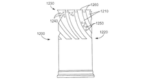
図12は、本発明によるディフューザ1200の別の実施例を示しており、ディフューザ1200は、ディフューザ200とほぼ同じであるが以下の点において異なる:
FIG. 12 shows another embodiment of a
ディフューザ1200のローブ1210は、ディフューザ1200の近位端部1220から遠位端部1230へ軸方向に真っ直ぐ延在していない;これらは、らせんパターンを形成するようにねじれている。ローブ1210は、また、近位端部1220をかなり越えるように半径方向に外側へ延在していない。ローブ1210は、また、小さいパーフォレーション1240(明瞭にするため数個のみ示す)と、大きいパーフォレーション1250(明瞭にするため数個のみ示す)とを具える。ローブ又はディフューザの他の範囲のパーフォレーションは、排気ガスをさらに拡散するいくつかの構成において所望される。ローブ1210は、また、排気の流れを改良するために傾斜した上端縁部1260を具える。
The
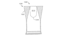
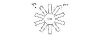
図13A及び13Bは、本発明による別の実施例のディフューザ1300を示しており、ディフューザ1300は、ディフューザ1300が複数のローブ1320の間の内部空間227中にブロック1310を具え、ローブ1320が10個であり、ディフューザ1300の遠位端部1330で半径方向にテーパ形ではない点が異なる以外は、ディフューザ200と同じである。ブロック1310は、内部空間227と同様の内部空間を具える本発明の様々な実施例において使用されてもよい。ブロック1310は、近位端部1340に空気力学的な目的のために形成されており、ローブ1320の半径方向の内側部分に溶接されるか別の方法で取り付けられており、内部空間227を塞いでここを通る排気ガスの流れを遮って、排気ガスが、ローブ1320だけを通ってディフューザ1300を出て大気中へ入るようにする。この装置は、最適な拡散と吸い込みのためのいくつかの構成において望ましく、中央から半径方向外側に配置された点(図4及び5のラインA乃至H)よりも熱くなる傾向にある排気ガスの流れの中央部分(図4及び5のラインJに示す)をなくすことができる。ブロック1310の他の実施例は、排気ガスが内部空間227を通って流れることを部分的にのみ妨げるブロックを具える。
FIGS. 13A and 13B show another embodiment of a
以下の概略的なフローチャート図は、論理上のフローチャート図として全体的に説明される。このように、示した順序及び表示したステップは、本発明の方法の一実施例を示している。図示した方法の1又はそれ以上のステップに対して機能、論理、又は効果、又はこの一部において同等である他のステップ及び方法を考慮してもよい。さらに、使用されているフォーマットや印は、方法の論理上のステップを説明するために提供されており、方法の範囲を限定するものではないと理解される。様々な種類の矢印や線がフローチャート図に使用されているが、対応する方法の範囲を限定するものではないと理解される。いくつかの矢印や他の連結部は、方法の論理上の流れのみを示すものとして使用される。例えば、矢印は、図示した方法に列挙されたステップ間の特定されていない待ち時間又は観察時間を示してもよい。さらに、特定の方法を行う順番は、図示した対応するステップの順番に正確に従っても、従わなくてもよい。 The following schematic flowchart diagram is generally described as a logical flowchart diagram. Thus, the order shown and the steps shown represent one embodiment of the method of the present invention. Other steps and methods that are equivalent in function, logic, or effect, or portions thereof, to one or more steps of the illustrated method may be considered. Further, it is understood that the format and indicia used are provided to illustrate the logical steps of the method and are not intended to limit the scope of the method. Various types of arrows and lines are used in the flowchart diagrams, but it is understood that they do not limit the scope of the corresponding method. Some arrows and other connections are used to indicate only the logical flow of the method. For example, the arrows may indicate unspecified latency or observation time between the steps listed in the illustrated method. Furthermore, the order in which the particular methods are performed may or may not follow exactly the order of the corresponding steps shown.
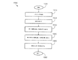
図14に、排気ガスを大気中へ拡散する方法の一実施例を示す。方法1500は、示すようにブロック1505から始まり、1510でハウジングが提供され、ハウジングは排気パイプ、ディフューザ、排気処理装置、又はエンジン排気系のいくつか他の部品、又は排気系の完成品である。ハウジングは、エンジン又は上流の排気系部品から排気ガスを受けて、排気は、例えば標準の円筒形排気パイプ又は処理装置などハウジング中の第1の通路を通って押し進められる1530。続いて、排気はハウジング中の第2の溝付の通路を通って押し進められ、排気ガスは溝によって形成されるローブを部分的に又は完全に通過する1540。排気は、それから大気へ直接放出され1550、方法が終了する1560。
FIG. 14 shows an embodiment of a method for diffusing exhaust gas into the atmosphere.
方法1500は、排気ガスの流れがほぼ均一に、大きな渦又は他の流体の障害を避けるよう上述したように、排気ガスが第2の通路の内側面のほぼ全体近くの第2の通路を通って押し進められるステップを追加するなど、本発明の範囲内で上記記載のステップ又は当業者に明らかな追加的なステップによって改良および/または拡張されてもよい。他の可能な追加には、ガスを第1の通路の第1の断面領域を通して、第2の通路の第1とほぼ同じ大きさの第2の断面領域を通して押し進めることを含む。他には、ガスを第1の通路の第1の断面円周部を通して、第2の通路の第1より大きい第2の断面円周部を通して押し進めることを含む。
The
本発明は、本発明の範囲又は必要な特徴から離れることなく他の特定の形でおこなわれてもよい。記載した実施例は全て説明としてのみ考慮されるものであり、制限するためのものではない。従って、本発明の範囲は、前記記載よりも添付した請求の範囲によって示される。請求の範囲と均等の意味や範囲内の全ての改良は、この範囲内で受け入れられる。 The present invention may be embodied in other specific forms without departing from the scope or necessary features of the invention. All described embodiments are considered to be illustrative only and are not intended to be limiting. Accordingly, the scope of the invention is indicated by the appended claims rather than the foregoing description. All modifications within the meaning and range equivalent to the terms of the claims are accepted within this range.
Claims (25)
近位端部と、遠位端部とを有するディフューザであって、前記近位端部は前記機関から排気ガスを受けるよう構成され、前記遠位端部は前記排気ガスを大気中へ放出するよう構成されているディフューザと;
前記遠位端部に少なくとも部分的に配置された複数のローブであって、前記排気ガスの少なくとも一部がこのローブを通過するように構成されているローブとを具えることを特徴とする装置。 In an apparatus for cooling exhaust gas from an internal combustion engine, the apparatus includes:
A diffuser having a proximal end and a distal end, wherein the proximal end is configured to receive exhaust gas from the engine, and the distal end releases the exhaust gas into the atmosphere. A diffuser configured as follows;
A plurality of lobes at least partially disposed at the distal end, wherein the lobes are configured to allow at least a portion of the exhaust gas to pass through the lobes. .
近位端部と、遠位端部とを有する排気管であって、前記近位端部は排気ガスを受けるよう構成され、前記遠位端部は前記排気ガスを大気中へ放出するよう構成されている排気管を具え;
前記遠位端部は、大気気体を前記排気ガス流動中へ吸い込んで前記排気ガスと前記大気気体を混合するための溝を具えることを特徴とする装置。 In an apparatus for diffusing exhaust gas, the apparatus includes:
An exhaust pipe having a proximal end and a distal end, the proximal end configured to receive exhaust gas, and the distal end configured to release the exhaust gas into the atmosphere Provided with an exhaust pipe;
The distal end comprises a groove for sucking atmospheric gas into the exhaust gas flow and mixing the exhaust gas and the atmospheric gas.
前記排気ガスを第1通路を通して押し進めるステップと;
前記排気ガスを複数のローブを通して押し進めるステップと;
前記排気ガスを前記ローブから大気中へ放出するステップと;
を具えることを特徴とする方法。 In a method for cooling exhaust gas, the method includes:
Pushing the exhaust gas through the first passage;
Forcing the exhaust gas through a plurality of lobes;
Releasing the exhaust gas from the lobe into the atmosphere;
A method characterized by comprising.
前記エンジンで生成される排気ガスをほぼ収容して方向付ける排気パイプと;
前記排気パイプ上に配設され、前記排気ガスの組成を改善するよう構成された排気処理機構と;
前記排気処理機構に機能的に取り付けられ、前記排気処理機構を適宜再生するよう構成された再生機構と;
ハウジングにおける前記排気処理機構の下流に配設された冷却機構であって、複数のローブを具え、前記排気ガスを前記排気パイプから受けて前記排気ガスを前記ローブを通して大気へ放出するよう構成された冷却機構と;
を具えることを特徴とするシステム。 In the exhaust treatment and cooling system of a diesel engine, the system:
An exhaust pipe that substantially contains and directs exhaust gas produced by the engine;
An exhaust treatment mechanism disposed on the exhaust pipe and configured to improve the composition of the exhaust gas;
A regeneration mechanism functionally attached to the exhaust treatment mechanism and configured to regenerate the exhaust treatment mechanism as appropriate;
A cooling mechanism disposed downstream of the exhaust treatment mechanism in the housing, comprising a plurality of lobes, configured to receive the exhaust gas from the exhaust pipe and discharge the exhaust gas to the atmosphere through the lobe. A cooling mechanism;
A system characterized by comprising.
Applications Claiming Priority (2)
| Application Number | Priority Date | Filing Date | Title |
|---|---|---|---|
| US11/333,656 US7316109B2 (en) | 2006-01-17 | 2006-01-17 | Lobed exhaust diffuser apparatus, system, and method |
| PCT/US2007/060643 WO2007084923A2 (en) | 2006-01-17 | 2007-01-17 | Lobed exhaust diffuser apparatus, system, and method |
Publications (1)
| Publication Number | Publication Date |
|---|---|
| JP2009536282A true JP2009536282A (en) | 2009-10-08 |
Family
ID=38261832
Family Applications (1)
| Application Number | Title | Priority Date | Filing Date |
|---|---|---|---|
| JP2008550561A Pending JP2009536282A (en) | 2006-01-17 | 2007-01-17 | Lobe-type exhaust diffuser device, system, and method |
Country Status (6)
| Country | Link |
|---|---|
| US (1) | US7316109B2 (en) |
| JP (1) | JP2009536282A (en) |
| CN (1) | CN101371016B (en) |
| BR (1) | BRPI0706875B1 (en) |
| DE (1) | DE112007000187T5 (en) |
| WO (1) | WO2007084923A2 (en) |
Cited By (2)
| Publication number | Priority date | Publication date | Assignee | Title |
|---|---|---|---|---|
| JP2015036550A (en) * | 2013-08-14 | 2015-02-23 | アルストム テクノロジー リミテッドALSTOM Technology Ltd | Improved intake arrangement in gas turbine power plant |
| JP7061221B1 (en) | 2020-11-30 | 2022-04-27 | マレリ株式会社 | Exhaust pipes for automobiles and mufflers for automobiles |
Families Citing this family (21)
| Publication number | Priority date | Publication date | Assignee | Title |
|---|---|---|---|---|
| US7757481B2 (en) * | 2006-01-17 | 2010-07-20 | Cummins Filtration Ip, Inc | Enclosed volume exhaust diffuser apparatus, system, and method |
| DE102006024576A1 (en) * | 2006-05-23 | 2007-11-29 | J. Eberspächer GmbH & Co. KG | Sheet-shaped component |
| US20080115989A1 (en) * | 2006-11-20 | 2008-05-22 | Matte Francois | Diesel engine vehicle configurations for evacuation of engine and/or exhaust system heat |
| US7779961B2 (en) * | 2006-11-20 | 2010-08-24 | Matte Francois | Exhaust gas diffuser |
| US20090014235A1 (en) * | 2007-07-13 | 2009-01-15 | Paccar Inc | Flow diffuser for exhaust pipe |
| US7971432B2 (en) * | 2007-07-13 | 2011-07-05 | Paccar Inc | Flow diffuser for exhaust pipe |
| KR100962811B1 (en) * | 2008-04-29 | 2010-06-09 | 기아자동차주식회사 | Manufacturing method of tail trim of automotive exhaust pipe |
| US8549850B2 (en) * | 2008-10-31 | 2013-10-08 | Cummins Filtration Ip, Inc. | Exhaust gas aspirator |
| DE102010014037A1 (en) | 2009-04-02 | 2010-11-04 | Cummins Filtration IP, Inc., Minneapolis | Reducing agent i.e. urea, decomposition system, has reducing agent injector coupled with exhaust chamber, where reducing agent injector is fixed in reducing agent injection connection part with exhaust gas in exhaust chamber |
| US8468811B2 (en) * | 2009-06-22 | 2013-06-25 | Paccar Inc | Thermal diffuser |
| US8479501B2 (en) * | 2009-07-20 | 2013-07-09 | International Engine Intellectual Property Company, Llc | Exhaust cooling module for SCR catalysts |
| US20110088379A1 (en) * | 2009-10-15 | 2011-04-21 | General Electric Company | Exhaust gas diffuser |
| US8402758B2 (en) * | 2010-03-05 | 2013-03-26 | Paccar Inc | Exhaust diffuser |
| EP2381071A1 (en) * | 2010-04-21 | 2011-10-26 | Siemens Aktiengesellschaft | Exhaust gas diffusor of a gas turbine |
| DE102010044483B4 (en) * | 2010-09-06 | 2016-10-27 | MTU Aero Engines AG | Flower mixer and turbomachine with such a flower mixer |
| DE102010045551A1 (en) * | 2010-09-16 | 2012-05-03 | Friedrich Boysen Gmbh & Co. Kg | Exhaust system for combustion engine of commercial vehicle, has end pipe comprising flow dividers designed and arranged such that partial streams of exhaust gas are separately discharged through outlet opening |
| WO2013095205A1 (en) * | 2011-12-22 | 2013-06-27 | Volvo Lastvagnar Ab | Exhaust colling apparatus |
| US9046005B2 (en) * | 2013-04-03 | 2015-06-02 | General Electric Company | Gas turbine exhaust diffuser with helical turbulator |
| US10100700B2 (en) | 2015-06-29 | 2018-10-16 | Tenneco Automotive Operating Company Inc. | Cantilevered flow distributing apparatus |
| US20170074145A1 (en) * | 2015-09-11 | 2017-03-16 | Avl Test Systems, Inc. | Exhaust Sampling System Including A Mixer That Mixes Exhaust Gas And Dilution Gas |
| US11319859B2 (en) * | 2019-05-30 | 2022-05-03 | Ford Global Technologies, Llc | Noise attenuating exhaust tail pipe |
Citations (5)
| Publication number | Priority date | Publication date | Assignee | Title |
|---|---|---|---|---|
| JPS51122212U (en) * | 1975-03-31 | 1976-10-04 | ||
| JPS54167215U (en) * | 1978-05-17 | 1979-11-24 | ||
| JPH08165952A (en) * | 1994-12-14 | 1996-06-25 | Ishikawajima Harima Heavy Ind Co Ltd | Fluid mixing device for jet engine |
| JPH09133046A (en) * | 1995-11-10 | 1997-05-20 | Ishikawajima Harima Heavy Ind Co Ltd | Fluid mixing device for jet engine |
| JP2003065156A (en) * | 2001-08-29 | 2003-03-05 | Ishikawajima Harima Heavy Ind Co Ltd | Robe mixer |
Family Cites Families (19)
| Publication number | Priority date | Publication date | Assignee | Title |
|---|---|---|---|---|
| US2370062A (en) * | 1941-03-29 | 1945-02-20 | Helfeda S A | Exhaust conduit |
| US2858853A (en) * | 1953-12-31 | 1958-11-04 | Lyon George Albert | Exhaust pipe extension |
| US2919720A (en) * | 1955-02-16 | 1960-01-05 | Harold E Nicholls | Flexible exhaust extension |
| US4077206A (en) * | 1976-04-16 | 1978-03-07 | The Boeing Company | Gas turbine mixer apparatus for suppressing engine core noise and engine fan noise |
| US4066214A (en) * | 1976-10-14 | 1978-01-03 | The Boeing Company | Gas turbine exhaust nozzle for controlled temperature flow across adjoining airfoils |
| DE3580606D1 (en) * | 1984-03-31 | 1991-01-03 | Mitsubishi Motors Corp | REGENERATION SYSTEM FOR A DIESEL PARTICLE OXYDING DEVICE. |
| US5058704A (en) * | 1988-11-21 | 1991-10-22 | Yu Chuen Huan | Turbo jet muffler |
| US4909346A (en) * | 1989-06-27 | 1990-03-20 | Nordam | Jet engine noise suppression system |
| US5611203A (en) * | 1994-12-12 | 1997-03-18 | Cummins Engine Company, Inc. | Ejector pump enhanced high pressure EGR system |
| US5884472A (en) * | 1995-10-11 | 1999-03-23 | Stage Iii Technologies, L.C. | Alternating lobed mixer/ejector concept suppressor |
| FR2740175B1 (en) * | 1995-10-18 | 1997-11-21 | Snecma | PYLONE DEVICE ASSOCIATED WITH THE MIXER OF AN EJECTION NOZZLE OF A MIXER FLOW TURBOREACTOR |
| US6233920B1 (en) * | 1999-02-01 | 2001-05-22 | Stage Iii Technologies, L.C. | Contoured thrust reverser and lobed nozzle noise suppressor for gas turbine engines |
| DE10007243C1 (en) * | 2000-02-17 | 2001-04-26 | Daimler Chrysler Ag | Exhaust gas backflow system for an IC motor has a mixing unit where fresh air is mixed with the exhaust at the opening into the backflow channel for an optimum exhaust/fresh air mixture |
| US6425382B1 (en) * | 2001-01-09 | 2002-07-30 | Cummins Engine Company, Inc. | Air-exhaust mixer assembly |
| DE10210971A1 (en) * | 2002-03-13 | 2003-09-25 | Daimler Chrysler Ag | Device for exhaust gas recirculation |
| US6776146B1 (en) * | 2003-01-27 | 2004-08-17 | International Engine Intellectual Property Company, Llc | Obstruction of flow to improve flow mix |
| DE102004057110B9 (en) * | 2004-11-26 | 2008-04-30 | Andreas Stihl Ag & Co. Kg | Exhaust system of a driven by an internal combustion engine implement |
| US7028663B1 (en) * | 2005-01-26 | 2006-04-18 | Kim Jay S | Fluid swirling device |
| US20070095057A1 (en) * | 2005-10-28 | 2007-05-03 | Field Nicholas C | Dynamic exhaust tip |
-
2006
- 2006-01-17 US US11/333,656 patent/US7316109B2/en active Active
-
2007
- 2007-01-17 DE DE112007000187T patent/DE112007000187T5/en active Pending
- 2007-01-17 BR BRPI0706875-1A patent/BRPI0706875B1/en active IP Right Grant
- 2007-01-17 WO PCT/US2007/060643 patent/WO2007084923A2/en not_active Ceased
- 2007-01-17 JP JP2008550561A patent/JP2009536282A/en active Pending
- 2007-01-17 CN CN2007800024038A patent/CN101371016B/en active Active
Patent Citations (5)
| Publication number | Priority date | Publication date | Assignee | Title |
|---|---|---|---|---|
| JPS51122212U (en) * | 1975-03-31 | 1976-10-04 | ||
| JPS54167215U (en) * | 1978-05-17 | 1979-11-24 | ||
| JPH08165952A (en) * | 1994-12-14 | 1996-06-25 | Ishikawajima Harima Heavy Ind Co Ltd | Fluid mixing device for jet engine |
| JPH09133046A (en) * | 1995-11-10 | 1997-05-20 | Ishikawajima Harima Heavy Ind Co Ltd | Fluid mixing device for jet engine |
| JP2003065156A (en) * | 2001-08-29 | 2003-03-05 | Ishikawajima Harima Heavy Ind Co Ltd | Robe mixer |
Cited By (4)
| Publication number | Priority date | Publication date | Assignee | Title |
|---|---|---|---|---|
| JP2015036550A (en) * | 2013-08-14 | 2015-02-23 | アルストム テクノロジー リミテッドALSTOM Technology Ltd | Improved intake arrangement in gas turbine power plant |
| JP7061221B1 (en) | 2020-11-30 | 2022-04-27 | マレリ株式会社 | Exhaust pipes for automobiles and mufflers for automobiles |
| WO2022113689A1 (en) * | 2020-11-30 | 2022-06-02 | マレリ株式会社 | Exhaust pipe and automobile muffler |
| JP2022087002A (en) * | 2020-11-30 | 2022-06-09 | マレリ株式会社 | Exhaust pipes for automobiles and mufflers for automobiles |
Also Published As
| Publication number | Publication date |
|---|---|
| WO2007084923A3 (en) | 2007-12-21 |
| CN101371016A (en) | 2009-02-18 |
| US7316109B2 (en) | 2008-01-08 |
| WO2007084923A2 (en) | 2007-07-26 |
| CN101371016B (en) | 2011-10-05 |
| US20070163249A1 (en) | 2007-07-19 |
| BRPI0706875B1 (en) | 2020-11-10 |
| DE112007000187T5 (en) | 2008-12-11 |
| BRPI0706875A2 (en) | 2011-04-12 |
Similar Documents
| Publication | Publication Date | Title |
|---|---|---|
| JP2009536282A (en) | Lobe-type exhaust diffuser device, system, and method | |
| US8549850B2 (en) | Exhaust gas aspirator | |
| EP2211038B1 (en) | Apparatus for cooling overheated gas in engine room | |
| CN101395353B (en) | Enclosed volume exhaust diffuser apparatus, system, and method | |
| US8046989B2 (en) | Cooling device for high temperature exhaust | |
| JP4988848B2 (en) | Truck exhaust diffuser | |
| US20110192153A1 (en) | Exhaust after treatment assembly | |
| CN102782408A (en) | Combustion appliance for raising the temperature of exhaust gas | |
| JP2008101623A (en) | Exhaust system for engine | |
| US8661798B2 (en) | Air entrainment component for vehicle exhaust system | |
| US7637099B2 (en) | Fluid entrainment apparatus | |
| US20080098499A1 (en) | Flow assembly for an exhaust system | |
| WO2016194201A1 (en) | Exhaust pipe structure for internal combustion engine | |
| US20090071136A1 (en) | Exhaust diffuser for an internal combustion engine | |
| CN102510934A (en) | Combined exhaust gas aftertreatment/air cleaner dust and ejector unit | |
| CN108590814B (en) | Engine exhaust aftertreatment device | |
| US7461506B2 (en) | Exhaust gas cooler | |
| WO2013095205A1 (en) | Exhaust colling apparatus | |
| JP6508301B2 (en) | Engine exhaust system | |
| RU2707339C1 (en) | Structurally improved device for diluting and dissipating exhaust gases of a vehicle | |
| US20080127641A1 (en) | Exhaust system | |
| JP2002242653A (en) | Muffler provide with exhaust passage parallel with center line thereof and having spark arrester function | |
| JP6508302B2 (en) | Engine exhaust system | |
| JP6151078B2 (en) | burner | |
| JP6109583B2 (en) | burner |
Legal Events
| Date | Code | Title | Description |
|---|---|---|---|
| A621 | Written request for application examination |
Free format text: JAPANESE INTERMEDIATE CODE: A621 Effective date: 20091112 |
|
| RD04 | Notification of resignation of power of attorney |
Free format text: JAPANESE INTERMEDIATE CODE: A7424 Effective date: 20100227 |
|
| A977 | Report on retrieval |
Free format text: JAPANESE INTERMEDIATE CODE: A971007 Effective date: 20110729 |
|
| A131 | Notification of reasons for refusal |
Free format text: JAPANESE INTERMEDIATE CODE: A131 Effective date: 20110802 |
|
| A601 | Written request for extension of time |
Free format text: JAPANESE INTERMEDIATE CODE: A601 Effective date: 20111102 |
|
| A602 | Written permission of extension of time |
Free format text: JAPANESE INTERMEDIATE CODE: A602 Effective date: 20111110 |
|
| A521 | Request for written amendment filed |
Free format text: JAPANESE INTERMEDIATE CODE: A523 Effective date: 20111202 |
|
| A131 | Notification of reasons for refusal |
Free format text: JAPANESE INTERMEDIATE CODE: A131 Effective date: 20120529 |
|
| A601 | Written request for extension of time |
Free format text: JAPANESE INTERMEDIATE CODE: A601 Effective date: 20120829 |
|
| A602 | Written permission of extension of time |
Free format text: JAPANESE INTERMEDIATE CODE: A602 Effective date: 20120905 |
|
| A521 | Request for written amendment filed |
Free format text: JAPANESE INTERMEDIATE CODE: A523 Effective date: 20121001 |
|
| A02 | Decision of refusal |
Free format text: JAPANESE INTERMEDIATE CODE: A02 Effective date: 20121218 |