JP2009532721A - Structured composite optical film - Google Patents
Structured composite optical film Download PDFInfo
- Publication number
- JP2009532721A JP2009532721A JP2009503248A JP2009503248A JP2009532721A JP 2009532721 A JP2009532721 A JP 2009532721A JP 2009503248 A JP2009503248 A JP 2009503248A JP 2009503248 A JP2009503248 A JP 2009503248A JP 2009532721 A JP2009532721 A JP 2009532721A
- Authority
- JP
- Japan
- Prior art keywords
- optical film
- layer
- film
- light
- structured surface
- Prior art date
- Legal status (The legal status is an assumption and is not a legal conclusion. Google has not performed a legal analysis and makes no representation as to the accuracy of the status listed.)
- Withdrawn
Links
Images


Classifications
-
- G—PHYSICS
- G02—OPTICS
- G02B—OPTICAL ELEMENTS, SYSTEMS OR APPARATUS
- G02B6/00—Light guides; Structural details of arrangements comprising light guides and other optical elements, e.g. couplings
- G02B6/0001—Light guides; Structural details of arrangements comprising light guides and other optical elements, e.g. couplings specially adapted for lighting devices or systems
- G02B6/0011—Light guides; Structural details of arrangements comprising light guides and other optical elements, e.g. couplings specially adapted for lighting devices or systems the light guides being planar or of plate-like form
- G02B6/0033—Means for improving the coupling-out of light from the light guide
- G02B6/005—Means for improving the coupling-out of light from the light guide provided by one optical element, or plurality thereof, placed on the light output side of the light guide
- G02B6/0053—Prismatic sheet or layer; Brightness enhancement element, sheet or layer
-
- G—PHYSICS
- G02—OPTICS
- G02B—OPTICAL ELEMENTS, SYSTEMS OR APPARATUS
- G02B5/00—Optical elements other than lenses
- G02B5/04—Prisms
-
- G—PHYSICS
- G02—OPTICS
- G02F—OPTICAL DEVICES OR ARRANGEMENTS FOR THE CONTROL OF LIGHT BY MODIFICATION OF THE OPTICAL PROPERTIES OF THE MEDIA OF THE ELEMENTS INVOLVED THEREIN; NON-LINEAR OPTICS; FREQUENCY-CHANGING OF LIGHT; OPTICAL LOGIC ELEMENTS; OPTICAL ANALOGUE/DIGITAL CONVERTERS
- G02F1/00—Devices or arrangements for the control of the intensity, colour, phase, polarisation or direction of light arriving from an independent light source, e.g. switching, gating or modulating; Non-linear optics
- G02F1/01—Devices or arrangements for the control of the intensity, colour, phase, polarisation or direction of light arriving from an independent light source, e.g. switching, gating or modulating; Non-linear optics for the control of the intensity, phase, polarisation or colour
- G02F1/13—Devices or arrangements for the control of the intensity, colour, phase, polarisation or direction of light arriving from an independent light source, e.g. switching, gating or modulating; Non-linear optics for the control of the intensity, phase, polarisation or colour based on liquid crystals, e.g. single liquid crystal display cells
- G02F1/133—Constructional arrangements; Operation of liquid crystal cells; Circuit arrangements
- G02F1/1333—Constructional arrangements; Manufacturing methods
- G02F1/1335—Structural association of cells with optical devices, e.g. polarisers or reflectors
- G02F1/133504—Diffusing, scattering, diffracting elements
- G02F1/133507—Films for enhancing the luminance
-
- G—PHYSICS
- G02—OPTICS
- G02F—OPTICAL DEVICES OR ARRANGEMENTS FOR THE CONTROL OF LIGHT BY MODIFICATION OF THE OPTICAL PROPERTIES OF THE MEDIA OF THE ELEMENTS INVOLVED THEREIN; NON-LINEAR OPTICS; FREQUENCY-CHANGING OF LIGHT; OPTICAL LOGIC ELEMENTS; OPTICAL ANALOGUE/DIGITAL CONVERTERS
- G02F1/00—Devices or arrangements for the control of the intensity, colour, phase, polarisation or direction of light arriving from an independent light source, e.g. switching, gating or modulating; Non-linear optics
- G02F1/01—Devices or arrangements for the control of the intensity, colour, phase, polarisation or direction of light arriving from an independent light source, e.g. switching, gating or modulating; Non-linear optics for the control of the intensity, phase, polarisation or colour
- G02F1/13—Devices or arrangements for the control of the intensity, colour, phase, polarisation or direction of light arriving from an independent light source, e.g. switching, gating or modulating; Non-linear optics for the control of the intensity, phase, polarisation or colour based on liquid crystals, e.g. single liquid crystal display cells
- G02F1/133—Constructional arrangements; Operation of liquid crystal cells; Circuit arrangements
- G02F1/1333—Constructional arrangements; Manufacturing methods
- G02F1/1335—Structural association of cells with optical devices, e.g. polarisers or reflectors
- G02F1/1336—Illuminating devices
- G02F1/133602—Direct backlight
- G02F1/133606—Direct backlight including a specially adapted diffusing, scattering or light controlling members
- G02F1/133607—Direct backlight including a specially adapted diffusing, scattering or light controlling members the light controlling member including light directing or refracting elements, e.g. prisms or lenses
-
- G—PHYSICS
- G02—OPTICS
- G02F—OPTICAL DEVICES OR ARRANGEMENTS FOR THE CONTROL OF LIGHT BY MODIFICATION OF THE OPTICAL PROPERTIES OF THE MEDIA OF THE ELEMENTS INVOLVED THEREIN; NON-LINEAR OPTICS; FREQUENCY-CHANGING OF LIGHT; OPTICAL LOGIC ELEMENTS; OPTICAL ANALOGUE/DIGITAL CONVERTERS
- G02F1/00—Devices or arrangements for the control of the intensity, colour, phase, polarisation or direction of light arriving from an independent light source, e.g. switching, gating or modulating; Non-linear optics
- G02F1/01—Devices or arrangements for the control of the intensity, colour, phase, polarisation or direction of light arriving from an independent light source, e.g. switching, gating or modulating; Non-linear optics for the control of the intensity, phase, polarisation or colour
- G02F1/13—Devices or arrangements for the control of the intensity, colour, phase, polarisation or direction of light arriving from an independent light source, e.g. switching, gating or modulating; Non-linear optics for the control of the intensity, phase, polarisation or colour based on liquid crystals, e.g. single liquid crystal display cells
- G02F1/133—Constructional arrangements; Operation of liquid crystal cells; Circuit arrangements
- G02F1/1333—Constructional arrangements; Manufacturing methods
- G02F1/1335—Structural association of cells with optical devices, e.g. polarisers or reflectors
- G02F1/1336—Illuminating devices
- G02F1/133602—Direct backlight
- G02F1/133611—Direct backlight including means for improving the brightness uniformity
-
- G—PHYSICS
- G02—OPTICS
- G02F—OPTICAL DEVICES OR ARRANGEMENTS FOR THE CONTROL OF LIGHT BY MODIFICATION OF THE OPTICAL PROPERTIES OF THE MEDIA OF THE ELEMENTS INVOLVED THEREIN; NON-LINEAR OPTICS; FREQUENCY-CHANGING OF LIGHT; OPTICAL LOGIC ELEMENTS; OPTICAL ANALOGUE/DIGITAL CONVERTERS
- G02F2201/00—Constructional arrangements not provided for in groups G02F1/00 - G02F7/00
- G02F2201/54—Arrangements for reducing warping-twist
Landscapes
- Physics & Mathematics (AREA)
- General Physics & Mathematics (AREA)
- Optics & Photonics (AREA)
- Nonlinear Science (AREA)
- Mathematical Physics (AREA)
- Chemical & Material Sciences (AREA)
- Crystallography & Structural Chemistry (AREA)
- Optical Elements Other Than Lenses (AREA)
- Laminated Bodies (AREA)
- Polarising Elements (AREA)
- Securing Globes, Refractors, Reflectors Or The Like (AREA)
Abstract
構造化表面を有する光学フィルムが、とりわけ、ディスプレイ内の光の伝播を管理するために使用される。ディスプレイが大型化するにつれて、剛性を維持するようにフィルムが補強されることがますます重要になる。本発明の光学フィルムは、ポリマーマトリックス内に埋め込まれた無機繊維を含む第1の層を有する。この第1の層は、そこを通過する光に光学的機能を提供するために構造化表面を有する。このフィルムは、様々な有益な光学的特性を持つ場合があり、例えば、第1の層を通って略垂直に伝播する光がある特定のレベル以下のヘイズにさらされる場合、あるいはフィルムに入射する光が輝度ゲインの最低値に従う場合がある。様々なフィルム製造方法が説明されている。 An optical film having a structured surface is used, among other things, to manage the propagation of light in the display. As displays get larger, it becomes increasingly important that the film be reinforced to maintain rigidity. The optical film of the present invention has a first layer comprising inorganic fibers embedded in a polymer matrix. This first layer has a structured surface to provide an optical function for light passing therethrough. The film may have a variety of beneficial optical properties, for example, light that propagates substantially vertically through the first layer is exposed to a certain level or less of haze, or is incident on the film. The light may follow the lowest value of luminance gain. Various film manufacturing methods have been described.
Description
本発明は、光学フィルムに関し且つ具体的にはディスプレイ、例えば、液晶ディスプレイ内で光を管理するために使用される構造化表面を有する光学フィルムに関する。 The present invention relates to an optical film and in particular to an optical film having a structured surface used to manage light in a display, eg, a liquid crystal display.
構造化屈折表面を有する光学フィルムは、光源からディスプレイパネルまでの光の伝播を管理するためのディスプレイに使用されることが多いプリズム状の輝度向上フィルムである。このようなフィルムの1つの説明例が、ディスプレイから光軸上の光の量を増加させるために使用されることが多いプリズム状の輝度向上フィルムである。 An optical film having a structured refractive surface is a prism-like brightness enhancement film often used in a display for managing the propagation of light from a light source to a display panel. One illustrative example of such a film is a prismatic brightness enhancement film that is often used to increase the amount of light on the optical axis from the display.
ディスプレイシステムが大型化するにつれて、フィルムの面積もまたより大きくなる。このような表面構造化フィルムは、薄型で、典型的には数十又は数百ミクロンの厚さであり、したがって、特に大型ディスプレイシステムに使用される場合には構造健全性をほとんど有していない。例えば、ある特定な厚さのフィルムが、携帯電話ディスプレイに使用するには十分に剛性であるのに対して、それと同一のフィルムはなんらかの追加の支持手段無しではテレビジョンやコンピュータモニターのような大型ディスプレイに使用するには剛性が不足するといえる。フィルムがより剛性であればまた、大型ディスプレイシステム組立プロセスが余り骨の折れないものになり且つ潜在的により自動化されるはずであり、よってディスプレイの最終組立費を低減させる。 As the display system becomes larger, the area of the film also increases. Such surface structured films are thin, typically tens or hundreds of microns thick, and therefore have little structural integrity, especially when used in large display systems. . For example, a film of a certain thickness is sufficiently rigid to be used in a mobile phone display, while the same film is a large film such as a television or computer monitor without any additional support. It can be said that the rigidity is insufficient for use in a display. If the film is stiffer, the large display system assembly process will also be less laborious and potentially more automated, thus reducing the final assembly cost of the display.
この表面構造化フィルムは、追加の剛性を提供するためにより厚くすることができる、あるいは大面積フィルムに使用するために厚いポリマー基材へ貼合わせてもよい。しかしながら、厚いフィルム又は厚い基材の使用は、ディスプレイ装置の厚さを増加させ、そしてまた重量及び光学的吸収率の増加につながる。より厚いフィルム又は基材の使用はまた、断熱を増加させ、ディスプレイから熱を移動させる能力を低減させる。更に、輝度を増加させたディスプレイに対する継続的な要求があり、それはより多くの熱がディスプレイシステムによって発生されることを意味する。これは、より高い加熱に伴う歪み影響、例えばフィルムの反りの増加をもたらす。これに加えて、表面構造化フィルムの基材への貼り合せは、デバイスに対して費用がかさみ、及びデバイスをより厚く及びより重くさせる。しかしながら、追加された費用は、ディスプレイの光学機能の著しい改善を結果としてもたらさない。 This surface structured film can be thicker to provide additional rigidity, or it may be laminated to a thick polymer substrate for use in large area films. However, the use of thick films or thick substrates increases the thickness of the display device and also leads to an increase in weight and optical absorption. The use of a thicker film or substrate also increases insulation and reduces the ability to transfer heat from the display. Furthermore, there is a continuing demand for displays with increased brightness, which means that more heat is generated by the display system. This results in increased distortion effects associated with higher heating, such as film warpage. In addition, the lamination of the surface structured film to the substrate is expensive for the device and makes the device thicker and heavier. However, the added cost does not result in a significant improvement in the optical function of the display.
本発明の一実施形態は、ポリマーマトリックス内に埋め込まれた無機繊維を含む第1層を有する光学フィルムを目的とする。この第1層は、構造化表面を有する。第1層を通って略垂直に伝播する光が、30%未満のバルクヘイズにさらされる。 One embodiment of the present invention is directed to an optical film having a first layer comprising inorganic fibers embedded within a polymer matrix. This first layer has a structured surface. Light that propagates substantially vertically through the first layer is exposed to less than 30% bulk haze.
本発明の別の実施形態は、ディスプレイパネルと、バックライトと、ディスプレイパネルとバックライトとの間に配置された強化フィルムと、を有するディスプレイシステムを目的とする。この強化フィルムは、構造化表面を有し、及びポリマーマトリックスで形成され、そのポリマーマトリックス内には無機繊維が埋め込まれている。強化フィルムを通って略垂直に伝播する光は、30%未満のバルクヘイズにさらされる。 Another embodiment of the present invention is directed to a display system having a display panel, a backlight, and a reinforced film disposed between the display panel and the backlight. This reinforced film has a structured surface and is formed of a polymer matrix in which inorganic fibers are embedded. Light that propagates substantially vertically through the reinforced film is subject to less than 30% bulk haze.
本発明の別の実施形態は、第1層を含む光学フィルムを目的とする。この第1層は、ポリマーマトリックス内に埋め込まれた無機繊維を含み且つ構造化表面を有する。この第1層は、第1層を通って伝播する光に対して少なくとも10%の輝度ゲインを提供する。 Another embodiment of the invention is directed to an optical film that includes a first layer. This first layer comprises inorganic fibers embedded in a polymer matrix and has a structured surface. This first layer provides a brightness gain of at least 10% for light propagating through the first layer.
本発明の別の実施形態は、光学フィルムの製造方法を目的とする。この方法は、構造化表面を有する成型工具を準備する工程、並びに、ポリマー及びモノマーの少なくとも一方で形成されるマトリックス内に埋め込まれた無機繊維を含む繊維強化層を準備する工程を含む。この繊維強化層は、繊維強化、構造化表面シートを生成するために成型工具に対して連続的に成型される。 Another embodiment of the present invention is directed to a method for producing an optical film. The method includes providing a molding tool having a structured surface and providing a fiber reinforced layer comprising inorganic fibers embedded in a matrix formed of at least one of a polymer and a monomer. This fiber reinforced layer is continuously molded against a molding tool to produce a fiber reinforced, structured surface sheet.
本発明の別の実施形態は、ポリマーマトリックス内に埋め込まれた無機繊維を有する第1層を含む光学フィルムを目的とする。この第1層は、構造化表面を有する。構造化表面から離れて向かい合う第1層の面に略垂直に入射する光のシングルパス透過率は、40%未満である。 Another embodiment of the present invention is directed to an optical film comprising a first layer having inorganic fibers embedded within a polymer matrix. This first layer has a structured surface. The single-pass transmittance of light incident substantially perpendicular to the surface of the first layer facing away from the structured surface is less than 40%.
本発明の上記の概要は、本発明の各図示の実施形態又はすべての実施を説明しようとするものではない。以下の図及び詳細な説明は、より具体的にこれらの実施形態を例証する。 The above summary of the present invention is not intended to describe each illustrated embodiment or every implementation of the present invention. The following figures and detailed description illustrate these embodiments more specifically.
添付の図面と共に本発明の様々な実施形態の詳細な説明を検討することで、本発明はより完全に理解され得る。 A more complete understanding of the invention can be obtained by considering the detailed description of various embodiments of the invention in conjunction with the accompanying drawings.
本発明は様々な変更例及び代替形状に柔軟に従うことができるが、それらの細目は図面で例を用いてこれまでに示したし、又詳細に記述されるであろう。しかしながら、その意図は、記述した特定の実施形態に本発明を限定することではないことを理解さるべきである。反対に、その意図は、添付された特許請求の範囲により規定されるように、本発明の精神及び範囲内にあるすべての変更例、同等の方法及び代わりの方法を網羅しようとするものである。 While the invention is susceptible to various modifications and alternative forms, specifics thereof have been shown above by way of example in the drawings and will be described in detail. It should be understood, however, that the intention is not to limit the invention to the particular embodiments described. On the contrary, the intent is to cover all modifications, equivalent methods and alternatives falling within the spirit and scope of the invention as defined by the appended claims. .
本発明は、光学システムに適用することができ、及び特に、1つ以上の光学フィルムを使用する光学ディスプレイシステムに適用することができる。光学ディスプレイ、例えば、液晶ディスプレイ(LCD)が大型化及び高輝度化するにつれて、ディスプレイ内の光学フィルムに対する需要がますます増大する。より大きいディスプレイは、反り、曲がり、及び弛みを防ぐために、より堅いフィルムを必要とする。しかしながら、フィルムの厚さをその長さ及び幅と共に拡大することは、より厚い及びより重いフィルムをもたらす。そのため光学フィルムが、厚さの増加を同時に伴わずに、大きいディスプレイに使用できるように、より堅くされることが望ましい。光学フィルムの剛性を増加させるための1つのアプローチは、フィルム内に強化用繊維を含むことである。繊維で強化されたフィルムはまた、複合フィルムと称されることもある。幾つかの例示的な実施形態では、繊維は、フィルムを通過する光の散乱がほとんどないか又は全くないように、屈折率がフィルムの周囲の物質とマッチされる。幾つかの実施形態では、光の方向を制御するために構造化表面を使用する際にフィルム内に光の散乱がほとんどないか又は全くないことは特に有利になり得る。例えば、プリズム状の輝度向上フィルムは、フィルムが本質的に無散乱である場合に光軸上の(法線方向の)輝度を一層増加させる。光学フィルムが薄い、例えば、〜0.2mm未満であることは多くの用途において望ましい場合があるが、厚さに対して特別な制限はない。幾つかの実施形態では、複合材料の利点及びより大きな厚さを結合させること、例えば、厚さ0.2〜2mmになり得るLCD−TVに使用される厚板を生成することが望ましい場合がある。この用途の目的のために、「光学フィルム」という用語はこれらのより厚い光学プレート又は光ガイド(光導波路)を含むと考えられるべきである。 The present invention can be applied to optical systems, and in particular to optical display systems that use one or more optical films. As optical displays, such as liquid crystal displays (LCDs), increase in size and brightness, the demand for optical films in the displays increases. Larger displays require stiffer films to prevent warping, bending, and sagging. However, expanding the thickness of the film along with its length and width results in a thicker and heavier film. It is therefore desirable for the optical film to be stiffer so that it can be used for large displays without simultaneously increasing the thickness. One approach to increasing the stiffness of an optical film is to include reinforcing fibers within the film. Fiber reinforced films are also sometimes referred to as composite films. In some exemplary embodiments, the fibers are matched in refractive index to the material surrounding the film such that there is little or no light scattering through the film. In some embodiments, it may be particularly advantageous to have little or no light scattering in the film when using a structured surface to control the direction of light. For example, a prismatic brightness enhancement film further increases the brightness on the optical axis (in the normal direction) when the film is essentially non-scattering. It may be desirable in many applications that the optical film is thin, for example, less than ˜0.2 mm, but there is no particular limitation on thickness. In some embodiments, it may be desirable to combine the advantages of composite materials and greater thicknesses, for example, to produce slabs used in LCD-TVs that can be 0.2-2 mm thick. is there. For the purposes of this application, the term “optical film” should be considered to include these thicker optical plates or light guides (light guides).
具体的には、本発明は構造化表面を有する各種有機/無機光学用複合材を目的とし、それらの構造化表面はなんらかの光学機能を有する。この構造化複合材は、複合層と「一体」となっている表面構造体を有し、もし必要であれば、複合層及び構造化表面が同時に形成されることを可能にする。構造化表面の光学機能は、一般に幾つかの光ガイド(ガイディング)特性を含む。構造化表面の有用な光ガイド特性の幾つかの例としては、リサイクル、視準もしくは光ガイド、レンジング、偏向、拡散、屈折、又は反射が挙げられる。この構造化表面は、以下を含むが、それらに限定されない、様々な形態を取る実用的な不連続を有している場合がある:湾曲している規則的な構造体、例えば、レンズ;(ミネソタ州、セントポールのスリーエム社(3MCompany)によって生産されるビキュイティ(Vikuiti)(商標)輝度向上フィルムにおけるような)プリズムのような規則的な直線で囲まれた構造体;マット又は拡散表面構造体のような偏向フィルム及びランダム構造体である。 Specifically, the present invention is directed to various organic / inorganic optical composites having a structured surface, the structured surface having some optical function. This structured composite has a surface structure that is “integral” with the composite layer, allowing the composite layer and the structured surface to be formed simultaneously if necessary. The optical function of the structured surface generally includes several light guiding (guiding) properties. Some examples of useful light guiding properties of structured surfaces include recycling, collimation or light guiding, ranging, deflection, diffusion, refraction, or reflection. This structured surface may have practical discontinuities that take various forms, including but not limited to: curved regular structures such as lenses; Structures surrounded by regular straight lines such as prisms (as in Vikuiti ™ brightness enhancement films) produced by 3M Company, St. Paul, Minnesota; mats or diffuse surface structures And a random structure.
本発明を包含してよいディスプレイシステム100の例示的な実施形態の概略分解図画が図1に示される。このようなディスプレイシステム100は、例えば、液晶ディスプレイ(LCD)モニター又はLCD−TVに使用されてよい。このディスプレイシステム100は、LCパネル102の使用に基づいており、典型的にはパネル板106間に配設された液晶(LC)104の層を含む。板106は、ガラスから形成されることが多く、又LC層104内の液晶の配向を制御するために、板106の内部表面上に電極構造体及びアラインメント層を含んでよい。当該電極構造体は一般に、LCパネル画素、隣接した範囲とは独立して液晶の配向が制御できるLC層の範囲を画定するように配置されている。カラーフィルタもまた、表示された画像に色を付与するための1以上の板106に含まれてもよい。
A schematic exploded view of an exemplary embodiment of a
上方吸収型偏光子108は、LC層104の上方に配置され、又下方吸収型偏光子110は、LC層104の下方に配置される。図示された実施形態では、上方及び下方吸収偏光子108、110は液晶パネル102の外部に位置している。この吸収偏光子108、110及びこのLCパネル102は共同して、バックライト112からディスプレイシステム100を通ってビューワーまで光の透過を制御する。
The
バックライト112は、LCパネル102を照明する光を発生する多くの光源116を含む。LCD−TV又はLCDモニターに使用されるこの光源116は、ディスプレイ装置100を横切って延在する線状、冷陰極剤蛍光管であることが多い。しかし、フィラメント又はアークランプ、発光ダイオード(LED)、フラット蛍光パネル若しくは外部蛍光ランプのような、他のタイプの光源が、使用されてもよい。光源のこのリストは、限定的又は網羅的なものを意図するのではなく、単に例示的なものである。
The
バックライト112はまた、LCパネル102から離れる方向に、光源116から下方へ伝播する光を反射する反射体118を含む。反射体118はまた、以下に説明するように、ディスプレイ装置100内で光を再利用するのに有用であり得る。反射体118はまた、鏡面反射体又は拡散反射体であってよい。反射体118として使用されてよい鏡面反射体の一例は、ミネソタ州、セントポールのスリーエム社(3M Company)から入手可能なビキュイティ(Vikuiti)(商標)鏡面反射性向上(Enhanced Specular Reflection)(ESR)フィルムである。適切な拡散反射体の例としては、拡散的に反射する粒子、例えば二酸化チタン、硫酸バリウム、炭酸カルシウム等が詰め込まれている重合体、例えば、ポリエチレンテレフタレート(PET)、ポリカーボネート(PC)、ポリプロピレン、ポリスチレン、及びその同類を含む。微孔質材料及び微細繊維含有材料を含む、拡散反射体の他の実施例が、米国特許出願公開第2003/0118805A1号に論述されている。
The
光管理層の配列体120は、バックライト112とLCパネル102との間に配置されている。当該光管理層は、ディスプレイ装置100の動作を改善するように、バックライト112から伝播する光に影響を及ぼす。例えば、光管理層の配列体120は拡散層122を含んでよい。当該拡散層122は、光源から受けた光を拡散するために使用され、これはLCパネル102に入射する照明光の均一性の向上をもたらす。それ故に、このことは、結果的により均一で明るい画像が視聴者によって知覚されることになる。
The
光管理層の配列体120はまた、反射型偏光子124を含んでよい。光源116は、典型的には非偏光光を作り出すが、下方吸収型偏光子110のみが単一の偏光状態を透過するので、光源116によって発生される光の約半分はLC層104まで透過されない。しかしながら、この反射型偏光子124は、ともすれば吸収されてしまうであろう光を反射させるために使用されてよい、したがってこの光は反射型偏光子124と反射体118間の反射によって再利用されてよい。反射型偏光子124により反射された光の少なくともいくらかは減偏光されてよい、及びその後で反射型偏光子124及び下方吸収型偏光子110を通ってLC層104まで透過される偏光状態で反射型偏光子124へ戻されてよい。このように、反射型偏光子124は光源116により発せられLC層104に到達する光の割合を増加させるために使用されてもよく、したがってディスプレイ装置100により生成される画像はより明るい。
The array of light management layers 120 may also include a
任意の好適なタイプの反射型偏光子、例えば、多層光学フィルム(MOF)反射型偏光子;連続/分散相偏光子又はコレステリック反射型偏光子のような、拡散反射偏光フィルム(DROF)が使用されてよい。 Any suitable type of reflective polarizer can be used, such as a diffuse reflective polarizer film (DROF), such as a multilayer optical film (MOF) reflective polarizer; a continuous / dispersed phase polarizer or a cholesteric reflective polarizer It's okay.
MOF、コレステリック及び連続/分散相反射型偏光子はすべて直交偏光状態で光を透過しながら1つの偏光状態の光を選択的に反射するために、フィルム、通常では高分子フィルム内で変動する屈折率プロファイルに依存する。MOF反射型偏光子の幾つかの例が、米国特許第5,882,774号に記載されている。MOF反射型偏光子の市販されている例としては、ミネソタ州、セントポールのスリーエム社(3M Company)から入手可能な拡散表面を備えるビキュイティ(Vikuiti)(商標)DBEF−II及びDBEF−D400多層反射型偏光子が挙げられる。 MOF, cholesteric, and continuous / dispersed phase reflective polarizers all reflect light in one polarization state while transmitting light in an orthogonal polarization state, so that the refraction varies within the film, usually a polymer film. Depends on the rate profile. Some examples of MOF reflective polarizers are described in US Pat. No. 5,882,774. Commercially available examples of MOF reflective polarizers include Vikuiti ™ DBEF-II and DBEF-D400 multilayer reflections with a diffusing surface available from 3M Company, St. Paul, Minnesota. Type polarizers.
本発明に関連して有用なDRPFの例には、共有米国特許第5,825,543号に記載されている連続相/分散相反射偏光子、及び共有米国特許第5,867,316号に記載されている拡散反射式多層偏光子が挙げられる。他の好適なタイプのDRPFは、米国特許第5,751,388号に記載されている。 Examples of DRPF useful in connection with the present invention include continuous / dispersed phase reflective polarizers described in commonly owned US Pat. No. 5,825,543, and commonly owned US Pat. No. 5,867,316. Examples include the diffuse reflection type multilayer polarizer described. Another suitable type of DRPF is described in US Pat. No. 5,751,388.
本発明に関連して有用なコレステリック偏光子のいくつかの例には、例えば米国特許第5,793,456号、及び米国特許公開第2002/0159019号に記載のものが含まれる。コレステリック偏光子は、出力側の四分の一波長遅延層(quarter wave retarding layer)とともに提供されることが多いので、コレステリック偏光子を透過した光が線状偏光に変換されるようになっている。 Some examples of cholesteric polarizer useful in connection with the present invention include those described, for example, in US Pat. No. 5,793,456, and US Patent Publication No. 2002/0159019. Cholesteric polarizers are often provided with an output quarter wave retarding layer so that light transmitted through the cholesteric polarizer is converted to linearly polarized light. .
光管理層の配列体120はまた、プリズム状の輝度向上層128を含む場合がある。輝度向上層とは、軸外れ光線を表示軸により接近した方向に方向変換する表面構造体を含む層である。これは、LC層104を通って光軸上を伝播する光の量を増加させ、したがって視聴者が見る画像の明るさを向上させる。一実施例は、プリズム状輝度向上層であり、これは屈折及び反射により照明光を方向変換させる、いくつものプリズム状素子を有する。ディスプレイ装置に使用され得るプリズム輝度向上層は、例えば、ミネソタ州、セントポールのスリーエム社(3M Company)から入手可能な、BEFII 90/24、BEFII 90/50、BEFIIIM 90/50及びBEFIIITを含むプリズム状フィルムのビキュイティ(Vikuiti)(商標)BEFII及びビキュイティBEFIIIファミリーが挙げられる。このプリズム状素子は、フィルムの幅を横切って延長する突起として、若しくはより短い素子として形成される場合がある。
The array of light management layers 120 may also include a prismatic
表面構造化フィルム200の例示的な実施形態は、図2に模式的に示される一体型繊維強化材を有する。この強化フィルム200は、ポリマーマトリックス204内に埋め込まれた強化用繊維202を含む。マトリックス204の少なくとも1つの表面には、構造化表面206が設けられている。図示された例示的な実施形態では、この構造化表面206は、表示軸に接近した方向に伝播するように光を方向変換させるためのプリズム状素子を有する、プリズム状輝度向上表面である。
An exemplary embodiment of the surface structured
無機繊維202は、ガラス、セラミック若しくはガラスセラミック材で形成される場合があり、そして1つ以上のトウ又は1つ以上の織物又は不織布層において、個々の繊維として、マトリックス204内に配列される場合がある。繊維202は、規則的なパターン又は不規則なパターンで配列される場合がある。強化高分子層の幾つかの異なる実施形態については、米国特許出願整理番号第11/125,580号にかなり詳細に論述されている。
The
本発明の多くの実施形態では、複合材の有機及び無機成分間の屈折率マッチングに起因して複合層が高度に透明である。構造化表面の複合層との一体化は、高温条件下で使用される場合に、構造化表面の反り又は屈曲の可能性を少なくさせる。 In many embodiments of the invention, the composite layer is highly transparent due to refractive index matching between the organic and inorganic components of the composite. Integration of the structured surface with the composite layer reduces the possibility of warping or bending of the structured surface when used under high temperature conditions.
更に、幾つかの現在存在している表面構造化フィルムの構造において、微小複製された表面構造体のベースフィルムへの良好な接着性を確実にするためにベースフィルム(基膜)の下塗りが極めて重要である。対照的に、一体化された構造化複合材を有する本発明の特定の実施形態の下では、ベースフィルム及び構造化表面は同一の樹脂系から生成できる。これにより総合加工プロセスが単純化され且つ別個のプライマー層及び下塗り工程の必要性がなくなる。他の選択肢として、このベースフィルムは1種の樹脂系で作製される複合材とすることも可能である一方、構造化表面は望ましい性状(添加剤、ナノ粒子を含有する、若しくは高い屈折率を有する)を有する第2の樹脂系により提供されることも可能であろう。 In addition, in some currently existing surface structured film structures, the base film (base film) subbing is extremely important to ensure good adhesion of the microreplicated surface structure to the base film. is important. In contrast, under certain embodiments of the invention having an integrated structured composite, the base film and the structured surface can be produced from the same resin system. This simplifies the overall processing process and eliminates the need for a separate primer layer and primer step. As another option, the base film can be a composite made of a single resin system, while the structured surface has desirable properties (additives, nanoparticles or high refractive index). It may also be provided by a second resin system having
モノリシック的に一体化された、表面構造化複合材はまた、ある特定の光学用途にとって重要な特性である薄型化、剛性、及び低い反りの特性を組み合わせて、構造化光学フィルムの剛性対厚さ比を最大化するための優れた戦略を提供する。剛性を維持しながらのフィルムの厚さの低減は、ハンドヘルド及びノート型コンピュータディスプレイにおいては特に重要であるが、省重量及び省スペースへの関心ゆえに、すべてのディスプレイ用途においても一般に望ましいことである。 Monolithically integrated, surface structured composites also combine the properties of thinning, stiffness, and low warpage, which are important properties for certain optical applications, to provide the stiffness versus thickness of structured optical films. Provide a good strategy for maximizing the ratio. While reducing film thickness while maintaining rigidity is particularly important in handheld and notebook computer displays, it is generally desirable in all display applications due to weight and space concerns.
マトリックス204及び繊維202の屈折率は、マッチするように又はマッチしないように選択されてよい。幾つかの例示的な実施形態では、その結果得られる物品が光源からの光に対してほとんど、又は完全に透明であるように屈折率をマッチさせることが望ましい場合がある。他の例示的な実施形態では、固有のカラー散乱効果を生成するか又はフィルムに入射する光の拡散透過又は反射を生成するかのいずれかのために屈折率を意図的にミスマッチさせることが望ましい場合がある。屈折率のマッチングは、樹脂マトリックス204の屈折率と同一のものに近い屈折率を有する適切な繊維202補強材を選定することにより、若しくは繊維202の屈折率に近いか又は同一の屈折率を有する樹脂マトリックスを生成することにより達成できる。
The refractive indices of the
ポリマーマトリックス204を形成する材料についてのx−、y−、及びz−方向の屈折率は、本明細書ではn1x、n1y及びn1zと呼ぶ。ポリマーマトリックス材204が等方性である場合、x−、y−、及びz−屈折率がすべて実質的にマッチしている。マトリックス物質が複屈折性である場合、x、y、及びzの屈折率の少なくとも1つは、他のものと異なる。繊維202の材料は、典型的に等方性である。それ故に、繊維202を形成する材料の屈折率はn2として与えられる。しかしながら、無機繊維202は、複屈折であってもよい。
The refractive indices in the x-, y-, and z-directions for the material forming the
幾つかの実施形態では、ポリマーマトリックス204が等方性であることが望ましい場合もあり、即ちn1x≒n1y≒n1z≒n1である。2つの屈折率は、もし2つの屈折率間の差が0.05未満、好ましくは0.02未満及びより好ましくは0.01未満であるならば、略同一であると考えられる。こうして、もしいずれの屈折率の対も0.05超過して違わなければ、好ましくは0.02未満であれば材料は等方性であると考えられる。さらに、幾つかの実施形態では、マトリックス204及び繊維202の屈折率が実質的にマッチしていることが望ましい。よって、マトリックス204と繊維202間の屈折率の差、n1とn2間の差は、少なくとも0.02未満、好ましくは0.01未満及びより好ましくは0.002未満と小さくすべきである。
In some embodiments, it may be desirable for the
他の実施形態では、ポリマーマトリックス204が複屈折であることが望ましい場合がある、この場合にはマトリックス屈折率の少なくとも一方が繊維202の屈折率とは異なる。繊維202が等方性である実施形態では、複屈折マトリックス204が、結果的に少なくとも1つの偏光状態にある光が補強層により散乱されることになる。散乱の量は、偏光状態が散乱される屈折率差の大きさ、繊維202のサイズ及びマトリックス204内の繊維202の密度を含む、幾つかの要因に依存する。更に、光は前方散乱(拡散透過)、後方散乱(拡散反射)、又は両方の組み合わせであってもよい。繊維強化層200による光の散乱は、米国特許出願整理番号第11/125,580号にかなり詳細に論述されている。
In other embodiments, it may be desirable for the
ポリマーマトリックス204に使用するのに好適な材料としては、光波長の望ましいレンジにわたって透明である熱可塑性及び熱硬化性ポリマーが挙げられる。幾つかの実施形態では、ポリマーが水に不溶性であることは特に有用である場合があり、ポリマーは疎水性であってもよく、若しくは吸水率が低い傾向を有してもよい。更に、好適なポリマー物質は、非晶質又は部分的結晶性であってもよく、そしてホモポリマー、コポリマー、又はこれらのブレンドを包含してもよい。ポリマー物質の例には、ポリ(カーボネート)(PC);シンジオタクチック及びアイソタクチックポリ(スチレン)(PS);C1〜C8アルキルスチレン;ポリ(メチルメタクリレート)(PMMA)及びPMMAコポリマーを包含する、アルキル、芳香族、及び脂肪族環含有(メタ)アクリレート;エトキシル化及びプロポキシル化(メタ)アクリレート;多官能性(メタ)アクリレート;アクリレート化エポキシ;エポキシ;及び他のエチレン性不飽和物質;環状オレフィン及び環状オレフィン性コポリマー;アクリロニトリルブタジエンスチレン(ABS);スチレンアクリロニトリルコポリマー(SAN);エポキシ;ポリ(ビニルシクロヘキサン);PMMA/ポリ(ビニルフロライド)ブレンド;ポリ(フェニレンオキシド)合金;スチレン系ブロックコポリマー;ポリイミド;ポリサルフォン;ポリ(ビニルクロライド);ポリ(ジメチルシロキサン)(PDMS);ポリウレタン;飽和ポリエステル;低複屈折性ポリエチレンを包含するポリ(エチレン);ポリ(プロピレン)(PP);ポリ(アルカンテレフタレート)、例えばポリ(エチレンテレフタレート)(PET);ポリ(アルカンナフタレート(alkanenapthalates))、例えばポリ(エチレンナフタレート)(PEN);ポリアミド;アイオノマー;ビニルアセテート/ポリエチレンコポリマー;セルロースアセテート;セルロースアセテートブチレート;フルオロポリマー;ポリ(スチレン)−ポリ(エチレン)コポリマー;ポリオレフィン性PET及びPENを包含するPET及びPENコポリマー;並びにポリ(カーボネート)/脂肪族PETブレンドが挙げられるが、これらに限定されない。(メタ)アクリレートという用語は、対応するメタクリレート又はアクリレート化合物のいずれかであるとして定義される。これらのポリマーは、光学的に等方性形態で使用されてもよい。
Suitable materials for use in the
幾つかの製品用途において、フィルム製品及び構成成分が、低濃度の不安定種(fugitivespecies)(低分子量、未反応、又は未変換の分子、溶解水分子(dissolved water molecules)、又は反応副生成物)を示すことは重要である。不安定種は、製品即ちフィルムの最終使用環境から吸収できる、例えば、水分子が初期製品製造からの製品又はフィルム内に存在できる、又は化学反応(例えば、縮合重合反応)の結果として生成できる。縮合重合反応からの小さい分子の発生の例は、ジアミン及び二塩基酸の反応からのポリアミドの形成中の水の分離である。不安定種(fugitive species)としてはまた、低分子量有機物質、例えばモノマー、可塑剤などを挙げることができる。 In some product applications, film products and components may contain low concentrations of fugitive species (low molecular weight, unreacted or unconverted molecules, dissolved water molecules, or reaction byproducts). ) Is important. Unstable species can be absorbed from the end use environment of the product or film, for example, water molecules can be present in the product or film from initial product manufacture, or can be generated as a result of a chemical reaction (eg, a condensation polymerization reaction). An example of the generation of small molecules from condensation polymerization reactions is the separation of water during the formation of polyamides from the reaction of diamines and dibasic acids. The fugitive species can also include low molecular weight organic materials such as monomers, plasticizers, and the like.
不安定種(fugitive species)は一般に、機能的製品又はフィルムの残りを構成する物質の大部分より低い分子量である。製品の使用条件は、例えば、製品又はフィルムの片面に、差別的により大きい熱応力を結果としてもたらす場合がある。これらの場合には、不安定種(fugitive species)はフィルムを通って移動する可能性があるか、又はフィルム若しくは製品の1つの表面から揮発して濃度勾配、全体の機械的変形、表面の変更、及び時には、望ましくないガス抜けを生じる可能性がある。ガス抜けは、製品、フィルム又はマトリックス中に空間若しくは気泡、又は他のフィルムへの接着に関しての問題をもたらす可能性がある。不安定種(fugitive species)は、潜在的に、溶媒和する、食刻する、又は製品用途における他の構成成分に望ましくない影響を及ぼす可能性もまたある。 A fugitive species is generally of lower molecular weight than the majority of the material that makes up the rest of the functional product or film. Product usage conditions may, for example, result in differentially greater thermal stresses on one side of the product or film. In these cases, fugitive species may migrate through the film or volatilize from one surface of the film or product to cause concentration gradients, overall mechanical deformation, surface modification. And sometimes undesired outgassing. Outgassing can lead to problems with spaces or bubbles in the product, film or matrix, or adhesion to other films. The fugitive species can also potentially undesirably solvate, etch, or otherwise affect other components in product applications.
幾つかの実施形態では、フィルム200のポリマーマトリックスが複屈折であることが望ましい場合があり、上に挙げたポリマーの幾つかが配向されたときに複屈折になる場合がある。特に、PET、PEN、及びこれらのコポリマー、並びに液晶ポリマーは、配向されたときに複屈折性の相対的に大きな値を表す。ポリマーは、押出成形及び延伸を包含する異なる方法を使用して配向されてもよい。延伸は、それが高度な配向を可能にし、並びに幾つかの容易に制御可能な外部パラメータ、例えば温度及び延伸比により制御されてもよいために、ポリマーを配向するために特に有用な方法である。
In some embodiments, it may be desirable for the polymer matrix of the
しかしながら、構造化表面複合材がまた実質的に非複屈折にされてよいことに注目することは重要である。これは幾つかの実施形態では、例えば、液晶ディスプレイ(LCD)の光学フィルム積み重ね内で構造化表面複合材の空間的設置の可能性を広げるので望ましい場合がある。対照的に、幾つかの従来の表面構造化フィルムは、望ましくない複屈折を顕在化させる場合がある。本明細書に記載される表面構造化複合材の実質的に光学的等方性の特性は、ディスプレイ用途における光学フィルム積み重ねの設計において柔軟性をもたらす場合がある。 However, it is important to note that structured surface composites may also be made substantially non-birefringent. This may be desirable in some embodiments because, for example, it opens up the possibility of spatial placement of structured surface composites within an optical film stack of a liquid crystal display (LCD). In contrast, some conventional surface structured films may reveal unwanted birefringence. The substantially optically isotropic properties of the surface structured composites described herein may provide flexibility in the design of optical film stacks in display applications.
マトリックス204には、フィルム200に対して望ましい特性をもたらすために各種添加剤が与えられてもよい。例えば、添加剤は次のものの内の1つ以上を含有してもよい:耐候剤、紫外線吸収剤、ヒンダードアミン光安定剤、酸化防止剤、分散剤、潤滑剤、静電気防止剤、顔料又は染料、核剤、難燃剤、及び発泡剤。
The
幾つかの例示的な実施形態は、経時的な黄ばみ及び曇りに耐性があるポリマーマトリックス物質を使用する場合がある。例えば、芳香族ウレタンのような幾つかの物質は、長期間紫外線に曝されるとき、不安定になり、及び時間と共に変色する。長期間にわたって同一のカラーを維持することが重要である場合には、このような材料を回避することが望ましい場合もある。 Some exemplary embodiments may use a polymer matrix material that is resistant to yellowing and clouding over time. For example, some materials, such as aromatic urethanes, become unstable and change color over time when exposed to ultraviolet light for extended periods. It may be desirable to avoid such materials where it is important to maintain the same color over time.
ポリマーの屈折率を変化させるか、若しくは材料の強度を増すために他の添加剤が、マトリックス204に与えられる場合がある。こうした添加剤には、例えば、ポリマーのビーズ又は粒子、及びポリマーのナノ粒子のような有機添加剤を挙げてもよい。幾つかの実施形態では、マトリックス204は、2つ以上の異なるモノマーの固有の比率を用いて形成され、各モノマーが重合されたときの異なる最終屈折率と関連づけられる。異なるモノマーの比率が、マトリックス204の屈折率を決定する。
Other additives may be provided to the
他の実施形態では、マトリックス204の屈折率を調節するために、又は材料の強度及び/又は剛性を向上させるために無機添加剤がマトリックス204に添加されてよい。例えば、無機物質は、ガラス、セラミック、ガラスセラミック、又は金属酸化物であってもよい。無機繊維に関して以下に論じられるガラス、セラミック、又はガラスセラミックのいずれの好適な種類が使用されてもよい。金属酸化物の好適な種類には、例えばチタニア、アルミナ、酸化スズ、酸化アンチモン、ジルコニア、シリカ、これらの混合物又はこれらの混合酸化物が挙げられる。このような無機材料は、例えば、練り合わされた、粉末にされた、形態がビーズ、フレーク又は微粒子、及びマトリックス内に分布された、ナノ粒子として与えられてよい。ナノ粒子は、例えば、気相又は溶液系加工を用いて合成されてよい。粒子のサイズは、約200nmを下回ることが好ましく、及びマトリックス204を通過する光の散乱を低減するために100nm又は更に50nm未満としてもよい。添加剤は、懸濁液の分散及び/又はレオロジー及び他の流体特性を最適化するために、又はポリマーマトリックスと反応するために官能化表面を有してもよい。他の種類の粒子としては、中空シェル、例えば中空ガラスシェルが挙げられる。
In other embodiments, inorganic additives may be added to the
任意の好適な種類の無機材料は、繊維202に使用されてよい。この繊維202は、フィルムを通過する光に対して実質的に透明であるガラスで形成されてよい。好適なガラスの例には、繊維ガラス複合物、例えばE、C、A、S、R、及びDガラスによく使用されるガラスが挙げられる。例えば、溶融シリカ及びBK7ガラスの繊維を包含する、より高品質のガラス繊維もまた使用されてもよい。好適なより高品質のガラスは、ニューヨーク州エルムスフォード(Elmsford)のショット・ノース・アメリカ社(Schott North America Inc.)のような幾つかの供給元から入手可能である。これらのより高品質のガラスから製造された繊維を使用することは、それらがより純粋でそのためより均一な屈折率及びより少ない含有物を有し、それは、散乱の低減及び透過率の向上をもたらすために、望ましい場合がある。また、繊維の機械的性質が均一になる可能性がより高い。より高品質のガラス繊維は、水分を吸収する可能性がより低く、ひいてはフィルムは、長期間の使用において、より安定になる。更に、ガラス中のアルカリ内容物は、水の吸収を増やすため、低アルカリガラスを使用することが望ましい場合がある。他の無機材料は、例えば、セラミック類又はガラスセラミック類が、第11/125,580号に論述されているように、繊維強化材に使用されてよい。
Any suitable type of inorganic material may be used for the
粒子又はチョップト繊維のような、延伸又はある特定の他の形成プロセスを必要とするポリマーにおいては不連続強化材が望ましい場合がある。例えば、米国特許出願整理番号第11/323,726号に記載されている、チョップトガラスで充填された押出成型された熱可塑性プラスチックが、繊維補強層として使用されてよい。他の用途にあっては、連続ガラス繊維強化材(即ち織物組織、トウ又は不織布)が使用されてよい。これらが熱膨張係数(CTE)の大幅な低減及び弾性率の向上につながることができるからである。これらの連続強化材は、押出し成型に基づいたプロセスではなく飽和/含浸及び硬化プロセスを用いて組み込むことがより実行可能である。 Discontinuous reinforcement may be desirable in polymers that require drawing or certain other forming processes, such as particles or chopped fibers. For example, an extruded thermoplastic filled with chopped glass, as described in US patent application Ser. No. 11 / 323,726, may be used as the fiber reinforcement layer. In other applications, continuous glass fiber reinforcement (ie, woven fabric, tow or nonwoven) may be used. This is because these can lead to a significant reduction in the coefficient of thermal expansion (CTE) and an improvement in the elastic modulus. These continuous reinforcements are more feasible to incorporate using a saturation / impregnation and curing process rather than an extrusion based process.
幾つかの例示的な実施形態では、少なくともいくらかの光が繊維202により拡散されるように、マトリックス204と繊維202との間で完全な屈折率マッチングを持たないことが望ましい場合がある。このような実施形態では、マトリックス204及び繊維202のいずれか又は両方が、複屈折であってよいか、若しくはマトリックス及び繊維の両方が等方性であってよい。繊維202のサイズに応じて、拡散が散乱から又は単純な屈折から生じる。繊維による拡散は非等方性であり、光は繊維の軸に対して横方向に拡散されてもよいが、繊維に対して軸方向には拡散されない。それ故に、拡散の性質は、マトリックス内の繊維の配向に依存する。繊維が、例えば、x−軸に平行に配列される場合には、次いで光はy−及びz−軸に平行な方向に拡散される。
In some exemplary embodiments, it may be desirable not to have perfect index matching between the
加えて、マトリックス204は、光を等方性散乱させる拡散粒子で詰め込まれてよい。拡散粒子は、マトリックスとは異なる屈折率、多くの場合より高い屈折率の粒子であり、約10μmまでの直径を有する。これらはまた複合材料に対して構造的強化をもたらすことができる。拡散粒子は、例えば、マトリックスの屈折率を調整するためのナノ粒子として使用する上記のような金属酸化物であってもよい。拡散粒子の他の好適な種類には、ポリスチレン若しくはポリシロキサン粒子のようなポリマー粒子、又はこれらの組み合わせが挙げられる。この拡散粒子はまた、ミネソタ州、セントポールのスリーエム社(3M Company)により生産される、タイプS60HSガラスバブル(Glass Bubbles)のような中空ガラス球体であってよい。拡散粒子は、光を拡散するだけに使用されてよく、光を拡散させるために屈折率がマッチしていない繊維と一緒に使用されてよく、若しくは光を拡散させ且つ方向変換させるために構造化表面と共に使用されてよい。
In addition, the
マトリックス204内の繊維202の幾つかの代表的な配列体としては、繊維のヤーン(糸)、トウ又はポリマーマトリックス内の一方向に配列されたヤーン、繊維織物、不織布、チョップト繊維、チョップト繊維マット(ランダム又は整然としたフォーマットで)、又はこれらのフォーマットの組み合わせが挙げられる。チョップト繊維マット又は不織布は、繊維の無作為の配列を有するのではなく、不織布又はチョップト繊維マット内に繊維の何らかの配列を提供するように、延伸され、圧力をかけられ、又は配向されてもよい。更に、マトリックス204は繊維202の複数層を含有してよく、例えば、マトリックス204は異なるトウ、織物組織等において繊維のより多くの層を含んでよい。図2に示される具体的な実施形態では、繊維202は2層に配列されている。
Some representative arrays of
強化表面構造化フィルムの製造に対する1つの代表的なアプローチについて、図3を参照して説明する。一般に、この取り組み方はマトリックス樹脂を予め調製された表面構造化層に直接塗布する工程を含む。製造配列体300は、繊維強化材302のロールを含むが、これはマトリックス樹脂306を収容する含浸浴304を通過させられる。樹脂306は、任意の好適な方法を用いて、例えば、繊維強化材302を一連のローラー308に通過させることにより繊維強化材302内に含浸される。
One representative approach to the production of a reinforced surface structured film is described with reference to FIG. In general, this approach involves applying the matrix resin directly to a previously prepared surface structured layer. The
一旦含浸強化材310が浴304から押し出しされると、必要であれば追加の樹脂312が塗布されてよい。この追加の樹脂312は、例えば、コーター314を用いて補強層310の上に塗布されてよい。このコーター314は、例えば、ナイフエッジコーター、コマコーター(図示)、バーコーター、ダイコーター、スプレイコーター、カーテンコーター、高圧噴射などの任意の好適なタイプのコーターであってよい。他の考察の中で、適用条件における樹脂の粘度が、適切なコーティング方法又は方法類を決定する。コーティング方法及び樹脂の粘度はまた、強化材がマトリックス樹脂により浸透される工程の間に、強化材から気泡が除かれる速度及び程度に影響する。
Once the impregnating
完成フィルムが低い散乱を有することが望ましい場合には、この段階では樹脂が繊維間の空間を完全に満たすことを確実にすることが重要であり、樹脂内に残った空所又は気泡は散乱センターとして作用する場合がある。気泡の発生を減らすために異なる手法が個々に又は組み合わせにより使用されてもよい。例えば、フィルムは補強層310全体にわたって樹脂306の散布を促進するために機械的に振動されてもよい。機械的振動は、例えば超音波源を使用して印加されてもよい。加えて、フィルムは気泡を樹脂306から抽出する真空を受けてもよい。これは、例えば、オプションの脱気装置316においてコーティングと同時に又はその後に行われてもよい。
If it is desired that the finished film have low scattering, it is important at this stage to ensure that the resin completely fills the space between the fibers, and any voids or bubbles remaining in the resin are scattered centers. May act as Different approaches may be used individually or in combination to reduce bubble generation. For example, the film may be mechanically vibrated to facilitate the spreading of the
この含浸補強層310は、次いで成型ロール318にかけてもよい。この層310は、樹脂内にくぼみを生成するように成型ロール318の構造化表面320に接触して保持される。この樹脂は、次いで成型ロール318と接触しながら固化されてよい。固化は、硬化、冷却、架橋、及びポリマーマトリックスが固体状態に達する結果となるいずれかの他のプロセスを包含する。図示された実施形態では、樹脂に放射線を印加するために放射線源322が使用される。他の実施形態では、樹脂306を固化するために、熱及び圧力、電子ビーム照射などを含むが、それらに限定されない異なるエネルギ−形態が樹脂に印加されてよい。他の実施形態では、樹脂306は冷却、重合、又は架橋により固化されてよい。冷却は、熱硬化性ポリマーの使用に特に適している技術である。例えば、成型ロール318を使用して樹脂を冷却してよい。
This impregnated reinforcing
幾つかの実施形態では、固化フィルム324が巻き取りロール326上に収集され、格納されるように十分に供給される。他の実施形態では、固化フィルム324はロールにかけるには堅すぎる場合があり、この場合にはそれは他の方法で格納され、例えば、フィルム324は格納用にシートに切断されてよい。
In some embodiments, the solidified
異なるタイプの表面構造体が、強化フィルム上に使用されてよい。図2は、輝度向上表面206を有する強化フィルム200を示し、これはフィルムを通過する軸外れ光207を軸線208により平行である方向へ方向変換させる。この軸線208は、フィルム200に対して垂直に延びている。光線207は、主光線であると考えてよい。幾つかの実施形態では、光線207は軸線208に対して30°超過の角度でフィルム200に入射し軸線に対して25°未満の角度でフィルム200から出射する。幾つかの実施形態では、主光線207のフィルム200を透過した後の方向はフィルム200に進入する前の主光線207の方向とは5°超過して異なり、つまりフィルム200は光線207を5°超過、幾つかの実施形態では10°超過及び幾つかの実施形態では20°超過の角度にわたって逸らせた。輝度向上表面は、平坦な側面を含むプリズムを含有するものだけには制限されない。他の例示的な実施形態では、プリズムの側面は湾曲していてもよく、若しくはプリズムはフィルムの幅全体に延在しなくてもよい。
Different types of surface structures may be used on the reinforced film. FIG. 2 shows a reinforced
表面構造化強化フィルム400の一実施形態が、図4Aに模式的に示されている。このフィルム400は、バックライトにおいて使用される光ガイド(光導波路)404から通過してきた光402の方向を変えるために使用される、補強偏向フィルムである。偏向フィルムからの光は、次いでディスプレイパネル(図示せず)に入射する前に1つ以上の追加の光管理フィルムを通過してよい。この構造化表面406は、入射面410及び反射面412を有する多くの突起部408を含む。この光402は、入射面410を通って突起部に進入し、そして反射面412において内部全反射される。この反射面412は、図示されているように、平坦でよく、若しくは小面があるか湾曲していてよく、あるいは何らか他の形状をとってもよい。
One embodiment of a surface structured reinforced
表面構造化、強化フィルム420の別の実施形態が、図4Bに模式的に示されている。構造化表面422が、光426を再帰反射させる多くのコーナーキューブ反射体424を備えている。
Another embodiment of a surface structured, reinforced
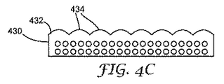
表面構造化、強化フィルム430の別の実施形態が、図4Cに模式的に示されている。この実施形態では、構造化表面432は1つ以上のレンズ434を含む。このレンズ434は、正の光パワー又は負の光学パワーを有してよい。
Another embodiment of a surface structured, reinforced
図4Dは、別の表面構造化強化フィルム440を模式的に示している。このフィルム440は、フレネルレンズの形態で構造化表面442を有する。
FIG. 4D schematically shows another surface structured reinforcing
図4Eは、別の表面構造化強化フィルム450を模式的に示している。このフィルム450は、回折構造化表面452を備える。この回折表面452は、フィルム450を通過する光454に対していずれの望ましい回折機能を発揮する回折光学素子として形成されてよい。例えば、回折表面は、光の焦点を合わす又は焦点をぼかす、1つ以上の特定の方向に光を方向変換させる、光を異なるカラー成分に分離する、あるいは形状を持った拡散体として機能するために使用されてよい。
FIG. 4E schematically shows another surface structured reinforcing
幾つかの例示的な実施形態では、表面構造化強化フィルムは対向面に2つの構造化表面を備えてよい。このようなデュアル表面構造化フィルム460例示的な実施形態が、図4Fに模式的に示されている。このフィルム460は、第1構造化表面462及び第2構造化表面464を有する。多数の異なるタイプの構造体が、輝度向上構造体、レンズ構造体、拡散構造体、回折構造体、偏向構造体、及び再帰反射性構造体を含み、2つの表面462、464上に組み合わせで提供されることができる。図示された実施形態では、上方構造化表面462は輝度向上構造体と構造化されている一方、下方構造化表面464はレンズ付表面と構造化されており、これはレンチキュラーレンズ付表面であってよい。デュアル表面構造化フィルムの各面上の構造体は、線状、同心、ランダム、若しくは何らか他のタイプのパターンであってよい。各面上のパターンのタイプは、同一である必要はない。
In some exemplary embodiments, the surface structured reinforcing film may comprise two structured surfaces on opposite sides. Such an exemplary embodiment of a dual surface structured
幾つかの実施形態では、一方の構造化表面が他方の構造化表面に対して位置合わせされる場合がある。例えば、片面上の反復輝度向上プリズム状の構造体のピッチがPであるならば、他面上のレンズのピッチは同一であってよく、1つのレンズからの光が1つの輝度向上表面に導かれるようにセットされてよい。このような配列体が図4Fに示されている。2つの表面上の構造体は、しかしながら、位置合わせされる必要がない。デュアル表面構造化フィルムは、2つの成型ロール間でフィルムを同時に押圧することによって、又は第1成型工具に対して片面を成型し、次いで第2成型工具に対して第2面を成型することによって製造できる。 In some embodiments, one structured surface may be aligned with the other structured surface. For example, if the pitch of the repetitive brightness enhancement prism-like structure on one side is P, the pitch of the lenses on the other side may be the same, and light from one lens is directed to one brightness enhancement surface. May be set to be Such an array is shown in FIG. 4F. The structures on the two surfaces, however, do not need to be aligned. Dual surface structured film is by pressing the film simultaneously between two molding rolls or by molding one side against the first molding tool and then molding the second side against the second molding tool. Can be manufactured.
幾つかの例示的な実施形態では、繊維強化構造化表面層は他の層に付着されてよい。図5は、第2光学層506に付着された表面構造化、補強層502を模式的に示している。この実施形態では、第2光学層506は構造化表面504に対向する面508に付着されている。この第2の光学層506は、偏光子層、偏向層などのような、任意の好適なタイプの層であってよい。この偏光子層は、反射型偏光子及び吸収型偏光子を含む、任意のタイプの偏光子層であってよい。この第2光学層506は、感圧接着剤又は積層接着剤のような、接着剤を用いて構造化表面層502に付着されてよい。
In some exemplary embodiments, the fiber reinforced structured surface layer may be attached to other layers. FIG. 5 schematically illustrates the surface structured, reinforcing
他の実施形態では、第2光学層が構造化表面に付着されてよい。強化輝度向上層602が第2層606に付着されている、1つの例示的な実施形態が、図6に模式的に示されている。構造化表面604の部分が、補強層602に向かい合っている第2層606の表面上に配置されている薄い接着剤層608内に埋め込まれている。構造化表面の別の光学フィルムへの付着が、米国特許第6,846,089号にかなり詳細に論述されている。一般的に、接着剤層608は表面構造体の高さと比較して相対的に薄い。この構造化表面604は、構造化表面608のかなりの部分が空気と境界面を持ったままになるように接着剤層608へ圧入される。これは空気と層602間の比較的に大きな屈折率の差を維持し、したがって、構造化表面604の屈折効果を保存する。他のタイプの表面構造化フィルムの構造化表面がまた、補強層に付着されてよいことが理解されるであろう。
In other embodiments, a second optical layer may be attached to the structured surface. One exemplary embodiment in which the enhanced
他の光管理層が、輝度向上以外の目的で備えられてもよい。これらの使用は、光の空間混合又はカラー混合、光源ハイディング、及び均一性向上を含む。これらの目的のために使用されてよいフィルムとしては、拡散フィルム、拡散板、特に反射層、カラー混合光ガイド又はフィルム、及び拡散光のピーク輝度光線が、入力光のピーク輝度光線の方向に平行でない方向に伝播する拡散システムが挙げられる。 Other light management layers may be provided for purposes other than brightness enhancement. These uses include spatial or color mixing of light, light source hiding, and uniformity enhancement. Films that may be used for these purposes include diffusing films, diffusing plates, especially reflective layers, color mixed light guides or films, and the peak luminance rays of diffused light parallel to the direction of the peak luminance rays of the input light. There is a diffusion system that propagates in a different direction.
強化表面構造体層が、1つを超える他の層に付着されてよい。例えば、光学層が構造化表面及び構造化表面層の他の表面の両方に付着されてよい。別の実施形態では、1つを超える他の層が強化構造化表面層の表面の一方に付着されてよい。第2光学層704が非構造化、例えば、平坦な、強化構造化表面層702の面に付着されている、1つの特別な実施例が、図7に模式的に示されている。第3光学層が、第2光学層に付着される。この第2及び第3光学層704、706が、偏光子層などを含む任意の望ましいタイプの光学層であってよい。加えて、第2及び第3層704、706のいずれかが補強層であってよい。以下に論述される一実施例、第2光学層704は反射型偏光子層であり、第3光学層706は平坦な補強層である。
The reinforced surface structure layer may be attached to more than one other layer. For example, an optical layer may be attached to both the structured surface and other surfaces of the structured surface layer. In another embodiment, more than one other layer may be attached to one of the surfaces of the reinforced structured surface layer. One particular embodiment in which the second
本発明の選択された実施形態が以下に記載される。これらの実施例は、制限することを意味せず、本発明の態様の幾つかを例示するのみである。 Selected embodiments of the invention are described below. These examples are not meant to be limiting and merely illustrate some of the aspects of the present invention.
複合フィルムの以下の実施例のすべてが、無機繊維強化材としてサウスカロライナ州、アンダーソンのヘクセル・リインフォースメント・コーポレイテッド社(Hexcel Reinforcements Corp.)により生産されるガラス繊維織物を使用した。このヘクセル(Hexcel)106(H−106)ファイバは、繊維と樹脂マトリックス間のカップリング剤としての役目を果たすために繊維に仕上げ剤を塗布した状態で納入業者から受け取られた。実施例では、使用されたすべてのH−106ガラス繊維はCS767シラン仕上剤を施した。他のシステムでは、仕上剤又はカップリング剤を塗布してない生繊維状態にあるガラス強化材を使用追加することが望ましい場合がある。 All of the following examples of composite films used glass fiber fabrics produced by Hexcel Reinforcements Corp., Anderson, South Carolina, as inorganic fiber reinforcement. This Hexcel 106 (H-106) fiber was received from a supplier with a finish applied to the fiber to serve as a coupling agent between the fiber and the resin matrix. In the examples, all H-106 glass fibers used were CS767 silane finish. In other systems, it may be desirable to use and add glass reinforcement in a raw fiber state without a finish or coupling agent applied.
表Iに記載された繊維試料の屈折率(RI)は、20x/0.50対物レンズによる透過単一偏光光(Transmitted Single Polarized Light)(TSP)、及び20x/0.50対物レンズによる透過位相差ゼルニケ(Transmitted Phase Contrast Zernike)(PCZ)を用いて測定された。繊維試料は、かみそりの刃を使用して繊維の部分を切断することにより、屈折率測定のために調製された。繊維は、スライドガラス上で様々なRI油の中に設置され、及びガラスカバースリップによりカバーされた。試料は、ツァイス・アクシオプラン(Zeiss Axioplan)(カール・ツァイス(Carl Zeiss)、ドイツ)を使用して分析された。RI油の較正が、ニューヨーク州、ロチェスター(Rochester)のミルトン・ロイ社(Milton Roy Inc.)製造のABBE−3L屈折計上で行なわれ、及び値はそれにしたがって調整された。位相差を伴うベッケ・ライン法(Becke Line Method)が、試料のRIを決定するために使用された。589nmのナトリウムD線の波長での屈折率、nDの値についての公称RIの結果は、各試料について±0.002の精度を有した。 The refractive index (RI) of the fiber samples listed in Table I are the transmitted single polarized light (TSP) with 20x / 0.50 objective and the transmission position with 20x / 0.50 objective. It was measured using a Transmitted Phase Contrast Zernike (PCZ). Fiber samples were prepared for refractive index measurement by cutting a portion of the fiber using a razor blade. The fibers were placed in various RI oils on glass slides and covered with glass cover slips. Samples were analyzed using a Zeiss Axioplan (Carl Zeiss, Germany). RI oil calibration was performed on an ABBE-3L refractometer manufactured by Milton Roy Inc., Rochester, NY, and values were adjusted accordingly. The Becke Line Method with phase difference was used to determine the RI of the sample. The refractive index at the wavelength of sodium D-line at 589 nm, the nominal RI result for the value of n D had an accuracy of ± 0.002 for each sample.
実施例1〜4に使用された各種樹脂に関する要約情報が表Iに示されている。 Summary information about the various resins used in Examples 1-4 is shown in Table I.

ダロクール(Darocour)1173及びダロクール(Darocour)4265gは、光開始剤であるのに対して、THFA(テトラヒドロフルフリルアクリレート)は官能性アクリレートモノマーである。表Iの残りの成分は架橋性樹脂である。エベクリル600(Ebecryl 600)は、ビスフェノール−Aエポキシジアクリレートオリゴマーである。 Darocour 1173 and Darocour 4265 g are photoinitiators, whereas THFA (tetrahydrofurfuryl acrylate) is a functional acrylate monomer. The remaining components in Table I are crosslinkable resins. Ebecryl 600 is a bisphenol-A epoxy diacrylate oligomer.
実施例1−モノリシック輝度向上複合層
この実施例においてポリマー樹脂に使用された原材料は以下であった。
Example 1 Monolithic Brightness Enhancement Composite Layer The raw materials used for the polymer resin in this example were:
繊維強化材は、CS767仕上剤を施したヘクセルスタイル(Hexcel Style)106繊維織物であった。繊維の屈折率は、1.551±0.002である。ここで、及び以下の実施例(69.3/29.7/1.0エベクリル(Ebecryl)600/TMPTA/ダロクール(Darocour)1173)のすべてにおいて使用される硬化複合樹脂混合物の屈折率は1.5517である。したがって、ポリマーマトリックスと繊維間の屈折率の差は、0.0007前後である。
The fiber reinforcement was
モノリシック複合材の調製は、PETの30cm×60cm(12インチ×24インチ)シートをアルミニウムの30.5cm×50.8cm×0.6cm(12インチ×20インチ×1/4インチ)シートの先端縁にテープで留めることにより開始した。プリズム状輝度向上構造体を生成するための成型工具が、PETの最上部上に置かれ、ガラス繊維織物のシートが成型工具の最上部上に置かれた。この成型工具は、50μmのプリズムピッチ及び90°の頂点角を有する、ビキュイティ(Vikuiti)(商標)BEF−IIIフィルムに使用されているものに似た波状のプリズム状輝度向上表面を生成するように設計された。 The preparation of the monolithic composite consists of a 30cm x 60cm (12 "x 24") sheet of PET and an edge of a 30.5cm x 50.8cm x 0.6cm (12 "x 20" x 1/4 ") sheet of aluminum. Started by taped to. A molding tool to produce a prismatic brightness enhancement structure was placed on the top of the PET and a sheet of glass fiber fabric was placed on the top of the molding tool. The molding tool produces a wavy prismatic brightness enhancement surface similar to that used in Vikuiti ™ BEF-III film with a prism pitch of 50 μm and a vertex angle of 90 °. Designed.
このガラス繊維織物は、30cm×60cm(12インチ×24インチ)PETの別のシートにより被覆され及びその先端縁はアルミニウムプレートの先端縁にテープで留められた。アルミニウムプレートの先端縁は、手動の貼合せ機内へ設置された。PETのトップシート及びガラス繊維は、成型工具へアクセスできるようにするために後ろ側へ剥がされた。樹脂(8〜10mL)のビーズが、貼合せロールに最も接近した縁部付近で、成型工具に塗布された。サンドイッチ構造が、樹脂をガラス繊維織物を通して押し込み、この織物を全面的にコーティングする貼合せ機を通って定常の速度で供給された。 The fiberglass fabric was covered with another sheet of 30 cm × 60 cm (12 inch × 24 inch) PET and its leading edge taped to the leading edge of the aluminum plate. The tip edge of the aluminum plate was placed in a manual laminator. The PET topsheet and glass fibers were peeled back to allow access to the molding tool. Resin (8-10 mL) beads were applied to the molding tool near the edge closest to the laminating roll. The sandwich structure was fed at a steady rate through a laminator that pushed the resin through the glass fiber fabric and coated the fabric over the entire surface.
アルミニウムプレートに依然付着されている、ラミネート材はヴァキュームオーブン内に設置され、そして60℃〜65℃の温度まで加熱された。このオーブンは、大気圧より下の水銀柱68.6cm(27インチ)まで真空にされ、そしてラミネート材は4分間ガス抜きされた。この真空は、オーブン内に窒素を導入することにより解除された。このラミネート材は、もう一度貼合せ機を通過させられた。 The laminate, still attached to the aluminum plate, was placed in a vacuum oven and heated to a temperature between 60 ° C and 65 ° C. The oven was evacuated to 68.6 cm (27 inches) of mercury below atmospheric pressure, and the laminate was degassed for 4 minutes. This vacuum was released by introducing nitrogen into the oven. This laminate was again passed through the laminator.
この樹脂は、15cm/秒(毎分30フィート)の速度において236W/cm(600W/インチ)で作動するフュージョン(Fusion)「D」タイプUVランプの下にラミネート材を通過させることにより硬化された。この複合材は、シート全体が成型工具から遊離されてしまうまでフリーエッジを後ろへ剥がすことによって工具から取り外された。下塗りしていないPET裏材もまた複合材から取り外され、「単層」モノリシックプリズム状の複合フィルムを残した。 The resin was cured by passing the laminate under a Fusion “D” type UV lamp operating at 236 W / cm (600 W / inch) at a speed of 15 cm / sec (30 feet per minute). . This composite was removed from the tool by peeling back the free edge until the entire sheet was released from the forming tool. The unprimed PET backing was also removed from the composite, leaving a “single layer” monolithic prism-like composite film.
実施例2−反射型偏光子上のモノリシック輝度向上複合フィルム
実施例1に記載されているようなモノリシック複合材は、3Mビキュイティ(Vikuiti)(商標)DBEF−P2に類似している下塗りした多層反射型偏光子(RP)の表面上に形成された。平坦な面を有する第2複合層は、機械的な支持のための偏光子層の他の面の上に設置された。この実施例では、偏光子層を複合層に接合するために貼合せ用接着剤が使用された。こうして、最終構造体が最上部から底部まで以下の層を有し、プリズム状の表面を含む透明な複合材/貼合せ用接着剤/RP/貼合せ用接着剤/透明な複合材である。この構造体は、図7に示すものとよく似ていた。
Example 2 Monolithic Brightness Enhancement Composite Film on Reflective Polarizer A monolithic composite as described in Example 1 is a subbed multilayer reflection similar to 3M Vikuiti ™ DBEF-P2. Formed on the surface of a type polarizer (RP). A second composite layer having a flat surface was placed on the other surface of the polarizer layer for mechanical support. In this example, a laminating adhesive was used to join the polarizer layer to the composite layer. Thus, the final structure has the following layers from the top to the bottom, and is a transparent composite / bonding adhesive / RP / bonding adhesive / transparent composite including a prismatic surface. This structure was very similar to that shown in FIG.
この貼合せ用樹脂は、以下のとおり形成された。 This laminating resin was formed as follows.
アクリレート樹脂のRP層の両面への接着を改善するためにプライマーが使用された。このプライマーは、ヘキサンジオールジアクリレート97%(w/w)及びベンゾフェノン3%(w/w)の混合物であった。フィルムのシートを下塗りするためには、3滴の溶液がフィルムの必要な面に塗布され、そしてティッシュを用いて拭き取りにより被覆された。過剰プライマー溶液は、きれいなティッシュで拭き取りにより除去されてよい。このコーティングは、空気雰囲気において15cm/秒(毎分30フィート)のライン速度において236W/cm(600W/インチ)で作動するフュージョン(Fusion)「D」タイプUVランプを用いて硬化された。RPの下塗りしたシートは、その後でRPと複合材間の貼合せ用接着剤をコーティング及び硬化することによって予め製造された透明な複合材に付着された。 A primer was used to improve the adhesion of the acrylate resin to both sides of the RP layer. The primer was a mixture of 97% (w / w) hexanediol diacrylate and 3% (w / w) benzophenone. To prime a sheet of film, 3 drops of solution were applied to the required side of the film and covered by wiping with a tissue. Excess primer solution may be removed by wiping with a clean tissue. The coating was cured using a Fusion “D” type UV lamp operating at 236 W / cm (600 W / inch) at a line speed of 15 cm / sec (30 feet per minute) in an air atmosphere. The RP primed sheet was then attached to a previously produced transparent composite by coating and curing a laminating adhesive between the RP and the composite.
構造化表面複合材に関する調整手順は、実施例1の場合と同一であった。加えて、平坦な透明な複合材は、以下の方法で形成された。PETの30cm×60cm(12インチ×24インチ)シートは、アルミニウムの30.5cm×50.8cm×0.6cm(12インチ×20インチ×1/4インチ)シートの先端縁にテープで留められた。ヘクセル(Hexcel)106ガラス繊維織物のシートは、PETの最上部の上に置かれた。このガラス繊維織物は、30cm×60cm(12インチ×24インチ)PETの別のシートにより被覆され、その先端縁はアルミニウムプレートの先端縁にテープで留められた。このアルミニウムプレートの先端縁は、手動の貼合せ機内へ設置された。PETの最上部シート及びガラス繊維織物は、PETの底部シートへのアクセスを可能にするために後ろ側に剥がされた。樹脂(6〜8mL)のビーズが、貼合せロールに最も接近したエッジ付近でPETの底部シートに塗布された。サンドイッチ構造が、定常な速度で貼合せ機を通って供給され、ガラス繊維織物を通して樹脂を上へ押し込んだ。
The adjustment procedure for the structured surface composite was the same as in Example 1. In addition, a flat transparent composite was formed by the following method. A 30 cm x 60 cm (12 inch x 24 inch) sheet of PET was taped to the leading edge of a 30.5 cm x 50.8 cm x 0.6 cm (12 inch x 20 inch x 1/4 inch) sheet of aluminum. . A sheet of
アルミニウムプレートに依然付着されていた、このラミネート材は、ヴァキュームオーブン内に設置され、60℃〜65℃の温度まで加熱された。このオーブンは、大気圧の下の水銀柱68.6cm(27インチ)まで真空にされ、ラミネート材は4分間ガス抜きされた。この真空は、オーブン内に窒素を導入することによって解除された。このラミネート材はもう一度貼合せ機を通過された。この樹脂は、15cm/秒(毎分30フィート)の速度において236W/cm(600W/インチ)で作動するフュージョン(Fusion)「D」タイプUVランプの下にラミネート材を通過させることにより硬化された。 This laminate, still attached to the aluminum plate, was placed in a vacuum oven and heated to a temperature between 60 ° C and 65 ° C. The oven was evacuated to 68.6 cm (27 inches) of mercury under atmospheric pressure and the laminate was degassed for 4 minutes. This vacuum was released by introducing nitrogen into the oven. This laminate was passed through the laminator once more. The resin was cured by passing the laminate under a Fusion “D” type UV lamp operating at 236 W / cm (600 W / inch) at a speed of 15 cm / sec (30 feet per minute). .
透明な複合材の下塗りしたRP層への付着は、PETの30cm×60cm(12インチ×24インチ)シートをアルミニウムの30.5cm×50.8cm×0.6cm(12インチ×20インチ×1/4インチ)シートの先端縁にテープで留めることにより開始した。RPの下塗りしたシートは、PET上に置かれた。PETの底部シートは、予め製造された透明な複合層から注意して取り除かれた。予め製造された透明な複合層は、複合材の面を下にして、RP層の最上部の上に置かれた。複合材の最上部PET層は、アルミニウムプレートの先端縁にテープで留められた。アルミニウムプレートの先端縁が、手動の貼合せ機内に設置された。複合材/PETのトップシートが、RPのシートへアクセスできるように後ろ側に引っ張られた。貼合せ用接着剤樹脂(〜5mL)のビーズが、貼合せロールに最も接近したRPの縁部に塗布された。サンドイッチ構造は、貼合せ機を通って定常な速度で供給され、RP及び予め製造された複合層の両方を貼合せ用樹脂でコーティングした。 The adhesion of the transparent composite to the primed RP layer was achieved by applying a 30 cm × 60 cm (12 inch × 24 inch) sheet of PET to a 30.5 cm × 50.8 cm × 0.6 cm (12 inch × 20 inch × 1 / 4 inches) started by taped to the leading edge of the sheet. The RP primed sheet was placed on PET. The bottom sheet of PET was carefully removed from the pre-fabricated transparent composite layer. A pre-fabricated transparent composite layer was placed on top of the RP layer with the composite side down. The top PET layer of the composite was taped to the leading edge of the aluminum plate. The tip edge of the aluminum plate was placed in a manual laminator. The composite / PET topsheet was pulled back to gain access to the RP sheet. A bead of bonding adhesive resin (~ 5 mL) was applied to the edge of the RP closest to the bonding roll. The sandwich structure was fed through the laminator at a steady rate, and both the RP and the pre-fabricated composite layer were coated with the laminating resin.
アルミニウムプレートに依然付着された、ラミネート材はラミネート材を15cm/秒(毎分30フィート)の速度において236W/cm(600W/インチ)で作動するフュージョン(Fusion)「D」タイプUVランプの下を通過させることにより硬化された。 Laminate still adhered to the aluminum plate is placed under a Fusion “D” type UV lamp operating at 236 W / cm (600 W / inch) at a rate of 15 cm / sec (30 ft / min). Cured by passing.
モノリシック輝度向上複合フィルムは、RPを平坦な透明複合材に付着する場合に用いる手順に似た手順を用いてRP/透明複合材に付着された。 The monolithic brightness enhancing composite film was attached to the RP / transparent composite using a procedure similar to that used to attach RP to the flat transparent composite.
実施例3−回折表面を含むモノリシック複合材
透明ガラス繊維複合材が、ポリイミド成型工具の上で回折ミクロ構造化表面で形成された。この物品は、こうして回折構造化表面を含む単一複合層を含む。試料は、成型工具がその層の上に回折構造体を設けたことを除いて、実施例1について上述したものと同じ方法で調整された。また、成型工具から硬化し複合材を除去するのを助けるために最初の使用前に剥離塗料が成型工具に塗布された。
Example 3-A monolithic composite transparent glass fiber composite containing a diffractive surface was formed with a diffractive microstructured surface on a polyimide molding tool. This article thus comprises a single composite layer comprising a diffractive structured surface. The sample was prepared in the same manner as described above for Example 1 except that the molding tool provided a diffractive structure on the layer. Also, a release coating was applied to the molding tool prior to first use to help cure and remove the composite material from the molding tool.
回折パターンは、1ミリメートル正方形、17ゾーン及び16レベルを有し、1cmの焦点距離で、632nmで作動するように設計された、正方形ゾーンプレートであった。光重合された「ポジ像」の部分断面図が、図8に模式的に示されている。この図は17ゾーンのうち3ゾーン、即ち中央ゾーン802及び2つのサイドゾーン804を示している。各ゾーンの最大高さ、hは632nmに達した。回折構造体は、ポジレンズとして機能する。
The diffraction pattern was a square zone plate with 1 millimeter square, 17 zones and 16 levels, designed to operate at 632 nm with a focal length of 1 cm. A partial cross-sectional view of a photopolymerized “positive image” is schematically shown in FIG. This figure shows three of the 17 zones, namely a
実施例4−レンズレット表面を含むモノリシック複合材
透明ガラス繊維複合材が、レンズレットミクロ構造化表面で形成された。実施例4についての試料調製手順は、成型工具はレンズレットアレイを生成するように設計されたものであったことを除いて、実施例1と同じであった。この手順は、レンズレットミクロ構造化表面工具の上でガラス繊維をコーティング及び硬化する行為を含んだ。また、剥離塗料は、工具から硬化した複合材を除去するのを助けるために最初の使用前に成型工具に塗布された。
Example 4 A monolithic composite transparent glass fiber composite comprising a lenslet surface was formed with a lenslet microstructured surface. The sample preparation procedure for Example 4 was the same as Example 1 except that the molding tool was designed to produce a lenslet array. This procedure involved the act of coating and curing glass fibers on a lenslet microstructured surface tool. The release paint was also applied to the molding tool before first use to help remove the cured composite from the tool.
レンズレット構造体は、30ミクロンのたるみを有し、横方向に75ミクロン、ポジレンズのアレイを含む。 The lenslet structure has a sag of 30 microns and includes an array of 75 microns laterally positive lenses.
光学測定
BEF状複合材実施例、実施例1及び2の相対ゲイン性能は、カリフォルニア州、チャッツワース(Chatsworth)のフォトリサーチ社(Photo Research, Inc)から入手可能な、MS−75レンズ付きスペクトラスキャン(SpectraScan)(商標)PR−650スペクトラカロリメーター(SpectraColorimeter)を用いて測定された。これらの値は、比較例として使用され既存の製品と比較された。この比較例は、ミネソタ州、セントポールのスリーエム社(3M Company)から市販される、ビキュイティ(Vikuiti)(商標)Thin−BEF−II、BEF−III−10−T、BEF−RP、及びDBEF−DTVを含んだ。Thin−BEF−IIは、50μm(2ミル)PET基材の上に90°頂角及び24μm高さを有するプリズムのパターンを有する。このパターンは、90/24パターンと呼ばれている。BEF−III−10−Tは、254μm(10mil)PET基材の上に90°頂角及び50μm高さを有するプリズムのパターンを有する。BEF−RPは、反射偏光基材、DBEF−Qの上に90/24プリズムパターンを有する。DBEF−DTVは、曇って見えるPC裏材を有するDBEF−Qにラミネートされた254μm(10ミル)ポリカーボネート(PC)基材の上に7μm半径を有する丸味のある頂点を含むプリズムを有する。これらのフィルムのすべてについての硬化プリズム樹脂屈折率は、〜1.58、PET平均屈折率が〜1.66であり、及びPC平均屈折率が〜1.58である。
The relative gain performance of the optically measured BEF-like composite examples, Examples 1 and 2, is Spectrascan with MS-75 lens available from Photo Research, Inc. of Chatsworth, CA. SpectraScan ™ PR-650 was measured using a SpectraColorimeter. These values were used as comparative examples and compared with existing products. The comparative examples are Vikuiti ™ Thin-BEF-II, BEF-III-10-T, BEF-RP, and DBEF-, commercially available from 3M Company, St. Paul, Minnesota. DTV included. Thin-BEF-II has a pattern of prisms having a 90 ° apex angle and a 24 μm height on a 50 μm (2 mil) PET substrate. This pattern is called a 90/24 pattern. BEF-III-10-T has a pattern of prisms having a 90 ° apex angle and a 50 μm height on a 254 μm (10 mil) PET substrate. BEF-RP has a 90/24 prism pattern on a reflective polarizing substrate, DBEF-Q. DBEF-DTV has prisms with rounded vertices with a 7 μm radius on a 254 μm (10 mil) polycarbonate (PC) substrate laminated to DBEF-Q with a PC backing that appears cloudy. The cured prism resin refractive index for all of these films is ˜1.58, the PET average refractive index is ˜1.66, and the PC average refractive index is ˜1.58.
工夫に富む光学フィルムの光学的性能を定量化するために用いられる一般的な相対的ゲイン試験方法について説明する。完全を期するために具体的な詳細が示されるが、以下の取り組み方の修正を用いて類似の結果が得られることが容易に認識されるべきである。カリフォルニア州、チャッツワースのフォトリサーチ社(Photo Research, Inc)から入手可能なMS−75レンズ付きスペクトラスキャン(SpectraScan)(商標)PR−650スペクトラコリメーター(SpectraColorimeter)を用いて、フィルムの光学的性能を測定した。拡散透過性中空ライトボックス上にフィルムを配置した。ライトボックスの拡散透過及び拡散反射は、ランベルト型として説明することができる。ライトボックスは、約6mmの厚さの拡散PTFE板から作製された約12.5cm×12.5cm×11.5cm(L×W×H)の大きさの六面中空キューブであった。ボックスの1つの面は、試料表面として選択されている。この中空ライトボックスは、試料表面において測定された〜0.83の拡散反射率を有した(例えば、以下に詳細に説明されるボックス反射率測定法により、400〜700nmの波長範囲にわたって平均された、〜83%)。ゲイン試験中、ボックスの底面内の約1cmの円孔を介して内部からボックスを照光した(底面は試料表面に対向し、光は内部から試料表面に導かれた)。この照明は、光を導くために使用される光ファイバ束(fiber-optic bundle)に付着された安定化した広帯域白熱光源を用いて提供される(マサチューセッツ州、マールバラ(Marlborough)及びニューヨーク州、オーバーン(Auburn)のショットフォステック社(Schott-Fostec LLC)製の直径~1cmファイバ束延長部を有するフォステック(Fostec)DCR−II)である。標準的な直線吸収偏光子(たとえばメレスグリオ(Melles Griot)03FPG007)を試料ボックスとカメラとの間に配置する。約34cm離間したライトボックスの試料表面にカメラの焦点を合わせ、カメラレンズから約2.5cmの位置に吸収偏光子を配置する。照射したライトボックスの輝度は、所定の位置に偏光子を配置するとともに試料フィルムのない状態で測定したところ、>150cd/m2であった。試料フィルムをボックスに概ね接触した状態にして試料フィルムをボックスの試料表面に平行に配置した時に、ボックスの試料表面の平面に対して法線入射方向で、試料輝度をPR−650によって測定する。この相対ゲインは、この試料輝度をライトボックスだけから同じ方法で測定された輝度と比較することにより計算される。迷光源を排除するために、全測定を黒色包囲体中で行った。反射偏光子を備えているフィルムアセンブリの相対ゲインを試験する場合、反射偏光子の通過軸を試験システムの吸収偏光子の通過軸にアライメントした。 A general relative gain test method used for quantifying the optical performance of an inventive optical film will be described. Although specific details are given for completeness, it should be readily recognized that similar results can be obtained using the following approach modifications. Optical performance of the film using a SpectraScan ™ PR-650 SpectraColorimeter with MS-75 lens available from Photo Research, Inc. of Chatsworth, Calif. Was measured. The film was placed on a diffuse transmissive hollow light box. The diffuse transmission and diffuse reflection of the light box can be described as a Lambertian type. The light box was a six-sided hollow cube with a size of about 12.5 cm × 12.5 cm × 11.5 cm (L × W × H) made from a diffused PTFE plate about 6 mm thick. One face of the box is selected as the sample surface. This hollow light box had a diffuse reflectance of ~ 0.83 measured at the sample surface (e.g. averaged over a wavelength range of 400-700 nm by box reflectometry as described in detail below) ˜83%). During the gain test, the box was illuminated from the inside through a circular hole of about 1 cm in the bottom of the box (the bottom faced the sample surface and the light was guided from the inside to the sample surface). This illumination is provided with a stabilized broadband incandescent light source attached to a fiber-optic bundle used to direct the light (Massachusetts, Marlborough and New York, Over Fostec DCR-II having a diameter to 1 cm fiber bundle extension manufactured by Schott-Fostec LLC of Auburn. A standard linear absorbing polarizer (eg Melles Griot 03FPG007) is placed between the sample box and the camera. The camera is focused on the sample surface of the light box that is about 34 cm apart, and an absorbing polarizer is placed about 2.5 cm from the camera lens. The luminance of the irradiated light box was> 150 cd / m 2 when measured with a polarizer in place and no sample film. When the sample film is placed in parallel with the sample surface of the box with the sample film substantially in contact with the box, the sample brightness is measured by PR-650 in the direction normal to the plane of the sample surface of the box. This relative gain is calculated by comparing this sample brightness with the brightness measured in the same way from the light box alone. All measurements were performed in a black enclosure to eliminate stray light sources. When testing the relative gain of a film assembly with a reflective polarizer, the pass axis of the reflective polarizer was aligned with the pass axis of the absorbing polarizer of the test system.
ライトボックスの拡散反射率は、直径15.25cm(6インチ)のスペクトラロン(Spectralon)被覆積分球と、安定化広帯域ハロゲン光源と、光源用の電源を用いて測定した。これらはすべて、ニューハンプシャー州サットンのラボスフェア社(Labsphere)から供給されている。積分球は、3つの開口ポートを有しており、1つのポート(直径2.5cm)は、入力光用であり、90度をなして第2の軸に沿った1つのポート(直径2.5cm)は、ディテクターポートとして用いられ、90度をなして第3の軸に沿った(すなわち最初の2つの軸に直交する)第3のポート(直径5cm)は、試料ポートとして用いられる。約38cm離間したディテクターポートにPR−650スペクトラカロリメーター(SpectraColorimeter)(上記のものと同一)の焦点を合わせた。拡散反射率が約99%であるラボスフェア社(Labsphere)製の較正反射標準(SRT−99−050)を用いて、積分球の反射効率を計算した。標準は、ラボスフェア社(Labsphere)により較正されたものであり、NIST標準(SRS−99−020−REFL−51)が基になっている。積分球の反射効率を以下のように計算した。 The diffuse reflectance of the light box was measured using a Spectralon-coated integrating sphere with a diameter of 15.25 cm (6 inches), a stabilized broadband halogen light source, and a power source for the light source. All of these are sourced from Labsphere, Sutton, New Hampshire. The integrating sphere has three aperture ports, one port (diameter 2.5 cm) is for input light and one port (diameter 2. .2) at 90 degrees along the second axis. 5 cm) is used as the detector port, and the third port (diameter 5 cm) along the third axis at 90 degrees (ie perpendicular to the first two axes) is used as the sample port. A detector port about 38 cm apart was focused on a PR-650 SpectraColorimeter (same as above). The reflection efficiency of the integrating sphere was calculated using a calibration reflection standard (SRT-99-050) manufactured by Labsphere with a diffuse reflectance of about 99%. The standard is calibrated by Labsphere and is based on the NIST standard (SRS-99-020-REFL-51). The reflection efficiency of the integrating sphere was calculated as follows.
球体輝度比=1/(1−R球体 *R標準)
この場合の球体輝度比は、参照試料で試料ポートを覆って検出器ポートで測定した輝度を、試料で試料ポートを覆わずに検出器ポートで測定した輝度で除すことによって得られる比である。この輝度比及び較正された標準の反射率(R標準)を知って、積分球の反射効率、R標準が計算できる。この値は次いで再度試料の反射率を測定するために類似の式において使用される、この場合ではPTFEライトボックス:
球体輝度比=1/(1−R球体 *R試料)
この場合には、球体輝度比は、試料を試料ポートに置いた時の検出器における輝度を、試料を用いずに測定した輝度で除すことによって得られる比として求める。上記からR球体が既知であるので、R試料を計算するのは簡単明瞭である。これらの反射率を4nmの波長間隔で計算し、400〜700nmの波長範囲にわたる平均として報告した。
Sphere luminance ratio = 1 / (1-R sphere * R standard )
The spherical luminance ratio in this case is a ratio obtained by dividing the luminance measured at the detector port by covering the sample port with the reference sample by the luminance measured at the detector port without covering the sample port with the sample. . Knowing this brightness ratio and the calibrated standard reflectivity (R standard ), the reflection efficiency of the integrating sphere, R standard , can be calculated. This value is then used again in a similar formula to measure the reflectance of the sample, in this case the PTFE light box:
Sphere luminance ratio = 1 / (1-R sphere * R sample )
In this case, the spherical luminance ratio is obtained as a ratio obtained by dividing the luminance at the detector when the sample is placed in the sample port by the luminance measured without using the sample. Since the R sphere is known from the above, calculating the R sample is straightforward. These reflectances were calculated at 4 nm wavelength intervals and reported as an average over the 400-700 nm wavelength range.
試料/ライトボックスアセンブリのCIE(1931)色度座標は、PR−650によって同時に記録される。これらの色度座標は、試料間の色差の定量的な尺度を与える。この相対ゲインは、試料輝度をライトボックスだけから同じ仕方で測定された輝度と比較することにより計算され、つまり、相対ゲインはフィルムと共に測定された輝度とフィルムなしで測定された輝度との比に等しく、すなわち、ゲイン、gは次式により与えられる:
g=Lf/Lo
ここに、Lfは、フィルムを所定位置に置いた測定輝度であり、Loはフィルムなしの測定輝度である。
The CIE (1931) chromaticity coordinates of the sample / light box assembly are recorded simultaneously by PR-650. These chromaticity coordinates give a quantitative measure of the color difference between samples. This relative gain is calculated by comparing the sample brightness to the brightness measured in the same way from the light box alone, i.e. the relative gain is the ratio of the brightness measured with the film to the brightness measured without the film. Equal, ie, gain, g is given by:
g = L f / L o
Here, L f is the measured luminance when the film is placed at a predetermined position, and L o is the measured luminance without the film.
測定は、迷光源を排除するために黒色包囲体中で実行された。反射偏光子を備えているフィルムアセンブリの相対ゲインを試験する場合、反射偏光子の通過軸を試験システムの吸収偏光子の通過軸にアライメントした。試験システムの吸収偏光子が所定位置にあり及びライトボックス上に試料なしの状態で、ライトボックスだけから測定された「ブランク」輝度は、〜275カンデラ/m2であった。 Measurements were performed in a black enclosure to eliminate stray light sources. When testing the relative gain of a film assembly with a reflective polarizer, the pass axis of the reflective polarizer was aligned with the pass axis of the absorbing polarizer of the test system. With the test system's absorbing polarizer in place and no sample on the light box, the “blank” brightness measured from the light box alone was ˜275 candela / m 2 .
ゲイン測定それ自身のばらつきは、きわめて低い(〜1%)。しかしながら、比較例における変動するヘイズ値レベル及びプリズムの幾何形状、及び工夫に富む試料の断面における気泡の可能な存在を含み、試料ばらつきの幾つかの潜在的な原因がある。実施例2を評価するときに考慮されるべき1つの追加的な要因は、実施例2のプリズムが実施例2のRP層の通過軸に垂直に位置合わせされていることである。これは実施例2だけが使用されるときには好ましい方位であるが、幾つかのフィルムアセンブリにおいて好ましくない場合もある(アセンブリに依存する)。この比較例BEF−RP及びDBEF−DTVは、対向するプリズム方位を有するが、これは光学的に好ましいからでなく、製造効率にとって好ましいからである。本発明の幾つかの実施形態では、輝度ゲインは10%より大きく、他の実施形態では50%より大きく及び他の実施形態では100%より大きい。 The variation of the gain measurement itself is very low (~ 1%). However, there are several potential sources of sample variation, including the varying haze value levels and prism geometry in the comparative example, and the possible presence of bubbles in the cross-section of the sample that is devised. One additional factor to be considered when evaluating Example 2 is that the prism of Example 2 is aligned perpendicular to the pass axis of the RP layer of Example 2. This is the preferred orientation when only Example 2 is used, but may not be preferred in some film assemblies (depending on the assembly). The comparative examples BEF-RP and DBEF-DTV have opposite prism orientations, not because they are optically preferred, but because of manufacturing efficiency. In some embodiments of the invention, the luminance gain is greater than 10%, in other embodiments greater than 50% and in other embodiments greater than 100%.
表IIは、実施例1〜4、比較例、及びいかなるフィルムもない、ライトボックスだけの結果を示す。一般に、複合材実施例の相対ゲインは対応する比較例に匹敵する、重要なカラー変化のないことは明らかである。例えば、実施例1、Thin−BEF−II−T、及びBEF−III−10−T間のゲインの極めて小さい差は、特筆に値する。これは実施例1構造化複合材が極めて低い光吸収及び散乱を有し、これはこれらのようなリサイクル光学フィルム用途にとって極めて重要であることを指摘している。実施例1樹脂がガラス繊維強化材の(より低い)屈折率にマッチするように設計されたという理由で実施例1のプリズム屈折率が比較例よりも低いという事実にもかかわらず、実施例1がThin−BEF−II−T、及びBEF−III−10−Tに匹敵するゲインを有することに注目することはまた興味深い。 Table II shows the results for Examples 1-4, the Comparative Example, and the light box alone without any film. In general, it is clear that the relative gains of the composite examples are not significant color changes comparable to the corresponding comparative examples. For example, the very small difference in gain between Example 1, Thin-BEF-II-T, and BEF-III-10-T deserves special mention. This indicates that Example 1 structured composite has very low light absorption and scattering, which is very important for recycled optical film applications such as these. Example 1 Despite the fact that the prism refractive index of Example 1 is lower than the Comparative Example because the resin was designed to match the (lower) refractive index of the glass fiber reinforcement, Example 1 It is also interesting to note that has a gain comparable to Thin-BEF-II-T and BEF-III-10-T.
構造化複合材実施例の角度出力は、下記したような、照明されたライトボックスの上に試料フィルムを載置することで測定された。輝度対出力角度は、ドイツ、カールスルーエ(Karlsruhe)のオートロニック・メルヒャ−社(Autronic-Melchers GmbH)で作製されたオートロニック(Autronic)コノスコープを用いて測定された。複合フィルムのそれぞれの測定結果が、図9及び10に示されている。図9は、ライトボックスだけと比較して、4実施例について、輝度を水平角度の関数として示している。曲線901は実施例1に、曲線902は実施例2に、曲線903は実施例3に、曲線904は実施例4に及び曲線905はライトボックスだけに対応する。図10は、ライトボックスのみと比較して、4実施例について、垂直角度の関数として示している。曲線1001は実施例1に、曲線1002は実施例2に、曲線1003は実施例3に、曲線1004は実施例4に、及び曲線1005はライトボックスだけに対応する。ライトボックスだけの出力は、ランバーティアン(Lambertian)に接近している。光ガイド用フィルムは、出力強度対角度を修正し、例えば、光の強度の有意の部分をゼロ度出力、即ちボックスの面に垂直方向に向けて方向変換する。光軸上の輝度のこの増加は、ゲインと呼ばれている。
The angular output of the structured composite example was measured by placing a sample film on an illuminated light box as described below. Luminance versus output angle was measured using an Autotronic conoscope made by Autronic-Melchers GmbH, Karlsruhe, Germany. The respective measurement results of the composite film are shown in FIGS. FIG. 9 shows the luminance as a function of horizontal angle for the four examples compared to the light box alone.
初期視準光の角度出力の分析のような、他の測定は、例えば、回折表面の性能をさらに特徴付けるであろう。回折及びレンズレット構造化表面の一般的な性能が当該技術分野において周知であり、ここに記載された複合材の実施例はそれに応じて性能を発揮するはずである。 Other measurements, such as analysis of the angle output of the initial collimated light, will further characterize the performance of the diffractive surface, for example. The general performance of diffractive and lenslet structured surfaces is well known in the art, and the composite embodiments described herein should perform accordingly.
光学フィルムの性能を特徴付けるために共通して使用される試験は、シングルパス透過率である。このタイプの透過率測定は、光再利用空洞内のフィルムの効果を考慮に入れていない。この試験において検出器に当たる光は、1回だけフィルムを通過した。さらに、入力光は典型的にはフィルムの平面に略垂直である角度で導かれ、そしてすべての透過光は透過角度に関係なく積分球内に集束される。最もよく市販されているヘイズメータ及びUV−Visスペクトロメーターを含み、多数の共通装置が、このタイプのシングルパス透過率をテストする。 A commonly used test to characterize the performance of optical films is single pass transmission. This type of transmission measurement does not take into account the effect of the film in the light recycling cavity. In this test, the light hitting the detector passed through the film only once. Furthermore, the input light is typically guided at an angle that is generally perpendicular to the plane of the film, and all transmitted light is focused into the integrating sphere regardless of the transmission angle. Numerous common devices test this type of single pass transmission, including the most commercially available haze meters and UV-Vis spectrometers.
多数の効率的な輝度向上フィルム及び光方向変換フィルムは、高いシングルパス透過率を有しない。特に、輝度向上構造体が、光源から離れて導かれ、大抵の輝度向上フィルムは低いシングルパス透過率を有する。これは、輝度向上フィルムが、再帰反射により、シングルパス透過率において測定される光軸上の光を再利用しながら垂直方向に向けて軸外れ光を方向変換することにより再利用バックライトにおける輝度向上を効率的に作り出すように設計されるからである。この正味効果は、ディスプレイシステムにおける効率的な輝度向上である。それ故に、相対ゲイン試験のような、他の特性評価試験と併合する際に、シングルパス透過率は、プリズム状輝度向上フィルムの光再利用効率を評価するために使用されることができる。したがって、輝度向上フィルムは、他の尺度と一緒に解釈されるときシングルパス透過率の低い値を示すことは、それらが再帰反射の高効率を指示するので望ましいことである。ある特定の輝度向上フィルムについての高いシングルパス透過率は、それが不規則性及び光散乱をほのめかし、完成されたディスプレイシステムにおいてあまり効率的でない輝度向上につながるので、望ましくない。幾つかの実施形態では、40%未満、及び他の実施形態では10%未満のシングルパス透過率を有することは望ましい。 Many efficient brightness enhancement films and light redirecting films do not have high single pass transmission. In particular, the brightness enhancement structure is guided away from the light source, and most brightness enhancement films have low single pass transmission. This is because the brightness enhancement film re-directs off-axis light in the vertical direction while reusing light on the optical axis measured at single-pass transmittance due to retroreflection, resulting in brightness in the reused backlight. This is because it is designed to produce improvements efficiently. The net effect is an efficient brightness improvement in the display system. Therefore, when combined with other characterization tests, such as relative gain tests, single pass transmission can be used to evaluate the light reuse efficiency of prismatic brightness enhancement films. Thus, it is desirable for brightness enhancement films to exhibit low values of single pass transmission when interpreted in conjunction with other measures because they indicate a high efficiency of retroreflection. High single pass transmission for certain brightness enhancement films is undesirable because it implies irregularities and light scattering, leading to less efficient brightness enhancement in the finished display system. In some embodiments it is desirable to have a single pass transmission of less than 40% and in other embodiments less than 10%.
本発明の代表的な光学フィルムは、パーキン・エルマー・ラムダ(Perkin Elmer Lambda)900UV−Visスペクトロメーター(Spectrometer)(450〜650nmから近似平均値を用いて)を用いてシングルパス透過率(%T)について試験された。この輝度向上構造体は、光源から離れて導かれたフィルムの面の上に位置した。結果は下の表IIIに示されている。 A representative optical film of the present invention uses a Perkin Elmer Lambda 900 UV-Vis Spectrometer (from 450 to 650 nm using an approximate average) and single pass transmission (% T ). This brightness enhancement structure was located on the surface of the film that was led away from the light source. The results are shown in Table III below.
表から分かるように、複合輝度向上フィルムは、ディスプレイシステムにおける高効率輝度向上を表示する、非常に低いシングルパス透過率を示した。 As can be seen from the table, the composite brightness enhancement film exhibited a very low single pass transmission that displayed a high efficiency brightness enhancement in the display system.
実施例1のリターダンス(位相差を含むアクソメトリックス社製ポラリメータ(Axometrics Polarimeter)を用いて測定された。このリターダンスは,先の比較例の幾つかとともに、追加の比較例(〜250μm厚さのポリカーボネート基材上のBEF−III 90/50パターンにおけるPC−BEF、7μm半径プリズム)と比較された。この結果は下の表IVに示されている。この計器を用いてプリズム状構造体を正確に測定するために、2つの技術が利用された。第一の技術は、プリズム構造体を「湿潤処理」して、光がフィルムを通過して検出器まで到達できるようするために、屈折率マッチング流体を採用した。第二の技術は、プリズムを互いに向かい合わせて2つのプリズムフィルムを積み重ねて載置して、フィルム間に水を浸み込ませることでそれらを光結合させることであった。許容できる再現性が、2つの技術の間に見られた。測定値の20〜30%程度のばらつきが、この試験で予想されると思われる(低いリターダンスレベルにおいてある程度のばらつきが下の「ブランク」測定値に示される)。複合材試料が、低いリターダンス及び低い複屈折を有することが判明した。リターダンス(ナノメートル単位)は、ここではdx(|no−ne|)として定義され、ここにdは試料の厚さであり及び数量(|no−ne|)は複屈折即ち試料の常光軸と異常光軸との間の屈折率差の大きさと同等である。ここで作製されたものに対応する複合層は、0.0001を下回る複屈折値に対応する2nm(600nm波長において)を下回るリターダンス値を有することが判明した。 The retardance of Example 1 (measured using an Axometrics Polarimeter with phase difference included. This retardance, along with some of the previous comparative examples, was added to an additional comparative example (˜250 μm thick). PC-BEF in a BEF-III 90/50 pattern on a polycarbonate substrate, 7 μm radius prism), the results of which are shown in Table IV below. To accurately measure, two techniques were utilized: the first technique “refracted” the prism structure to allow light to pass through the film and reach the detector. Rate matching fluid was adopted.The second technique was to place two prism films on top of each other with the prisms facing each other, soaking water between the films An acceptable reproducibility was seen between the two techniques, and a variation of as much as 20-30% of the measurements would be expected in this test. (Some variability is shown in the “blank” measurements below at low retardance levels.) It was found that the composite sample had low retardance and low birefringence. here dx is defined as, where d is the thickness of the sample and the quantity (| | n o -n e) (| n o -n e |) is the ordinary axis and an extraordinary optical axis of the birefringence i.e. sample The composite layer corresponding to that produced here has a retardance value below 2 nm (at a wavelength of 600 nm) corresponding to a birefringence value below 0.0001. Can And Akira.
ある特定の表面構造化フィルム、特に輝度向上フィルムにあっては、フィルム内で起こるバルク拡散性を制限することが多くの場合望ましい。バルク拡散性は、光学体の内部の中で起こる光散乱(光学体の表面において起こる光散乱に対向する)として定義される。構造化表面材料のバルク拡散性は、屈折率マッチングオイルを使用して構造化表面を湿潤処理し且つ標準ヘイズメータを用いてヘイズ値を測定することで測定できる。ヘイズ値は、多数の市販ヘイズメータを用いて測定できる及びASTM D1003に準じて定義できる。バルク拡散性を制限することは典型的には構造化表面が光の方向転換、輝度向上などにおいて最も効率的に動作することを可能にする。本発明の幾つかの実施形態にあっては、バルク拡散性が低いことが好ましい。特に、幾つかの実施形態では、ヘイズ値は30%未満であってよく、他の実施形態では10%未満及び他の実施形態では1%未満であってよい。 For certain surface structured films, particularly brightness enhancement films, it is often desirable to limit the bulk diffusivity that occurs within the film. Bulk diffusivity is defined as light scattering that occurs within the interior of the optical body (as opposed to light scattering that occurs at the surface of the optical body). The bulk diffusivity of the structured surface material can be measured by wetting the structured surface using refractive index matching oil and measuring the haze value using a standard haze meter. The haze value can be measured using a number of commercially available haze meters and can be defined according to ASTM D1003. Limiting bulk diffusivity typically allows structured surfaces to operate most efficiently in turning light, improving brightness, and the like. In some embodiments of the present invention, low bulk diffusivity is preferred. In particular, in some embodiments, the haze value may be less than 30%, in other embodiments less than 10%, and in other embodiments less than 1%.
実施例1及びある特定の他のフィルム試料についてバルク拡散性が構造化表面をカルギーユ社(Cargille)製(シリーズRF、カタログ18005)認定屈折率マッチングオイルを用いて湿潤処理し且つガラス板に対してフィルムを湿潤処理することで測定された。この湿潤フィルム及びガラス板が次いでBYKガードナ(Gardner)社製ヘイズガードプラス(Haze-GardPlus)(カタログ番号4725)の光路に置かれ、そしてヘイズ値が記録された。この場合、ヘイズ値は8°円錐の外側に散乱される透過光を透過光の全量で除した割合として定義される。光はフィルムに垂直に入射する。 For Example 1 and certain other film samples, the bulk diffusive structured surface was wet treated with Cargille (Series RF, catalog 18005) certified index matching oil and applied to a glass plate It was measured by wet processing the film. The wet film and glass plate were then placed in the light path of a BYK Gardner Haze-GardPlus (Catalog Number 4725) and the haze value was recorded. In this case, the haze value is defined as the ratio of transmitted light scattered outside the 8 ° cone divided by the total amount of transmitted light. Light enters the film perpendicularly.
バルクヘイズ値、即ちフィルムの表面において発生するいかなる拡散からでもなく、ポリマーマトリックスのバルク内の伝播から発生する曇り、の測定値が下の表Vに示される。実施例1のフィルムは、1.55の屈折率を有するオイルを用いて湿潤処理された。他のすべてのプリズム試料は、屈折率1.58のオイルを用いて湿潤処理された。 The measurement of the bulk haze value, i.e. the haze generated from propagation in the bulk of the polymer matrix, not from any diffusion occurring at the surface of the film, is shown in Table V below. The film of Example 1 was wet treated with an oil having a refractive index of 1.55. All other prism samples were wet treated with an oil having a refractive index of 1.58.
機械的試験
フィルム試料のガラス転移温度は、フィルム張力ジオメトリとともにティ・エイ・インスツルメント社(TA Instruments)Q800シリーズ・ダイナキック・メカニカル・アナライザー(Dynamic Mechanical Analyzer)(DMA)を用いて測定された。温度掃引実験は、2℃/分において−40℃から200℃までの範囲にわたって動的ひずみモードで実施された。貯蔵弾性率及びタンデルタ(損失係数)が、温度の関数として報告された。タンデルタ曲線のピークは、フィルムのガラス転移温度、Tgを識別するために使用された。このTgは、実施例1で使用されたものと非常によく似た複合層の上で測定され、そして71℃の値が得られた。同一樹脂(強化材はない)の対応する試料の上で測定されたTgは90℃であった。ばらつきは、測定要因のせいである。複合層に使用された樹脂材料は、ここに記載された実施例のすべてについて実質的に同一のTgを有した。幾つかの実施形態では、Tgの値が120℃未満であることが望ましい場合もある。
The glass transition temperature of the mechanical test film samples was measured using a TA Instruments Q800 Series Dynamic Mechanical Analyzer (DMA) with film tension geometry. . The temperature sweep experiment was performed in dynamic strain mode over a range from -40 ° C to 200 ° C at 2 ° C / min. Storage modulus and tan delta (loss factor) were reported as a function of temperature. The peak of the tan delta curve was used to identify the glass transition temperature, T g of the film. This T g was measured on a composite layer very similar to that used in Example 1 and a value of 71 ° C. was obtained. The T g measured on the corresponding sample of the same resin (no reinforcement) was 90 ° C. Variation is due to measurement factors. The resin material used for the composite layer had substantially the same T g for all of the examples described herein. In some embodiments, it may be desirable value T g of is less than 120 ° C..
貯蔵弾性率及び剛性(張力)が、フィルム張力ジオメトリとともにティ・エイ・インスツルメント社(TA Instruments)モデル番号Q800 ダイナミック・メカニカル・アナリシス(Dynamic Mechanical Analyzer)(DMA)を用いて測定された。DMA試験に関連した用語は、ASTM D−4065及びASTM D−4092に準じて定義できる。報告値は、室温(24℃)においてである。剛性の結果は表VIにまとめられている。これらの測定は、24℃〜28℃の範囲内の温度において行われた。表は、複合材料を用いて得ることができる貯蔵弾性率の著しい増加を示している。貯蔵弾性率は、フィルム特性の厚さとは無関係な尺度を提供するので非常に重要である。これらのデータには試験方法及び複合材試料の実験室規模の試作の両方から若干のばらつきが予想される。 Storage modulus and stiffness (tension) were measured using a TA Instruments model number Q800 Dynamic Mechanical Analyzer (DMA) with film tension geometry. Terms related to the DMA test can be defined according to ASTM D-4065 and ASTM D-4092. Reported values are at room temperature (24 ° C.). The stiffness results are summarized in Table VI. These measurements were made at temperatures in the range of 24 ° C to 28 ° C. The table shows the significant increase in storage modulus that can be obtained using the composite material. Storage modulus is very important because it provides a measure independent of the thickness of the film properties. These data are expected to vary slightly from both the test method and the laboratory scale prototyping of composite samples.
引張弾性率及び剛性のこれらの高い値は、最終物品構造及びジオメトリに応じて、潜在的な曲げ剛性にも同様に対応すると見なすことができ、高弾性率層の適切な設置が結果的に高い曲げ剛性を有する物品をもたらすことになる。より高い剛性は、(ディスプレイの光学部品の反り又は曲げが少ないことによる)取扱いの容易さ、薄型及び軽量ディスプレイ、並びにより優れたディスプレイ均一性を可能にする。完成物品の実際の性能は、繊維の配列及び物品の完成ジオメトリに依存する。例えば、「釣り合いの取れた」物品を作製することが望ましい、例えば、材料が硬化又は加熱と同時に一定の方向に曲がったり又はねじれたりする傾向がないように、単一の中央複合層又は2つの対称的に対向した複合層のいずれかがある場合である。ここで試験される複合材試料は、構造において実質的に釣り合いがとれている。 These high values of tensile modulus and stiffness can be considered to correspond to potential bending stiffness as well, depending on the final article structure and geometry, resulting in high proper placement of the high modulus layer This will result in an article having bending stiffness. Higher rigidity allows for ease of handling (due to less warping or bending of the display optics), thin and light displays, and better display uniformity. The actual performance of the finished article depends on the fiber arrangement and the finished geometry of the article. For example, it may be desirable to create a “balanced” article, eg, a single central composite layer or two so that the material does not tend to bend or twist in a certain direction upon curing or heating. This is the case with any of the symmetrically opposed composite layers. The composite samples tested here are substantially balanced in structure.
表VIは、試料の簡単な説明と一緒に試料番号を掲げている。この表はまた、偏光子の通過又はブロック軸を基準にした、又は機械上で製造されるようなウェブに対する方向を基準にした測定の方位を掲げている。「機械」は方向ダウンウェブ方向に対応するのに対して、「横断」方向はウェブを横切る方向に対応する。この表はまた平均貯蔵弾性率、平均剛性、及び厚さ、Tを掲げている。この厚さは、小野測器(Ono Sokki)(日本、横浜)により作製されているG−233ディジタル・リニア・ゲージ(digital linear gauge)を用いて測定された。 Table VI lists the sample number along with a brief description of the sample. This table also lists measurement orientations relative to the pass or block axis of the polarizer or relative to the web as produced on a machine. “Machine” corresponds to the direction down-web direction, whereas “transverse” direction corresponds to the direction across the web. The table also lists the average storage modulus, average stiffness, and thickness, T. This thickness was measured using a G-233 digital linear gauge made by Ono Sokki (Yokohama, Japan).
熱膨張係数(CTE)は、パーキン・エルマー(Perkin Elmer)TMA 7上で標準熱機械分析(standard thermal-mechanical analysis)を用いて測定された。標準TMA試験に関連した用語は、ASTM E−473及びASTM E−11359−1に準じて定義できる。温度掃引実験は、10℃/分において30℃〜110℃の範囲にわたって膨張モードにおいて実施された。CTEの測定値は表VIIにまとめられている。 The coefficient of thermal expansion (CTE) was measured on a Perkin Elmer TMA 7 using standard thermal-mechanical analysis. Terms related to standard TMA testing can be defined according to ASTM E-473 and ASTM E-11359-1. The temperature sweep experiment was performed in expansion mode over a range of 30 ° C. to 110 ° C. at 10 ° C./min. CTE measurements are summarized in Table VII.
この複合材試料は、商業用比較例と比べて一般的に類似の又はより低いCTEを呈示する。商業用偏光子試料の幾つかについて、偏光子の通過及びブロック軸に沿って測定されるときCTE性能は異なる(偏光子の加工及び分子方位による)。これらの場合において、たとえCTEが他の軸に沿っては比較的に影響を受けないとしても(例えば、平均CTEを下げる及び/又はCTEの通過状態及びブロック状態を等しくする方向に移動させることが望ましい)偏光子の高CTE軸に沿ってCTEを下げることが特に重要であり且つ有用である。この有用な効果は、複合材試料において実証されている。このより低いCTEは、幾つかのディスプレイ用途において反りの低減及び光学的均一性の向上に寄与しているはずである。 This composite sample generally exhibits a similar or lower CTE as compared to a commercial comparative example. For some of the commercial polarizer samples, CTE performance is different (depending on polarizer processing and molecular orientation) when measured along the polarizer pass and block axis. In these cases, even if the CTE is relatively unaffected along the other axis (eg, lowering the average CTE and / or moving the CTE through and block states to equalize). It is particularly important and useful to lower the CTE along the high CTE axis of the polarizer). This useful effect has been demonstrated in composite samples. This lower CTE should contribute to reduced warpage and improved optical uniformity in some display applications.
フィルム組み合わせ/アセンブリ
空間的周期性パターンは、ある特定の空間周波数及び角度関係において他の周期性パターンと組み合わされるとき望ましくないモアレ効果を時々生じさせることがある。それ故に、場合によっては、複数複合層間、(同一又は隣接したフィルムの)複合層と任意の構造化フィルム表面との間、若しくは複合層とピクセル、光ガイドドットパターン、又はLED発生源のような、任意のディスプレイシステム要素との間に生成されるモアレパターンを最大化するために強化繊維の間隔、配列、又はバイアス角度を調節することが望ましい場合がある。また、強化用繊維の屈折率マッチングがほぼ完全であり、且つ複合層がほぼ完全に平滑である場合には、有意なモアレパターンが発生しないはずである。
Film combination / assembly spatial periodic patterns can sometimes produce undesirable moire effects when combined with other periodic patterns at certain spatial frequencies and angular relationships. Therefore, in some cases, such as between multiple composite layers, between composite layers (of the same or adjacent films) and any structured film surface, or composite layers and pixels, light-guided dot patterns, or LED sources, etc. It may be desirable to adjust the spacing, alignment, or bias angle of the reinforcing fibers in order to maximize the moire pattern generated between any display system elements. In addition, if the refractive index matching of the reinforcing fibers is almost perfect and the composite layer is almost perfectly smooth, no significant moire pattern should occur.
前述の複合光学物品が、既存の光学フィルムがアセンブリへ組み合わされるのと全く同じ方法でアセンブリへ有利に組み合わされてよいことが理解されるであろう。アセンブリの一例は、「直交BEF」であり、そこではそれらのプリズム溝が、他方の非プリズム状の表面に隣接した一方のフィルムのプリズム状表面と、おおよそ直交するように、2枚のBEFフィルムが互いに隣接して設置される。したがって、有益な光学効果を達成するために複合フィルムを各種他の光学フィルムと組み合わせることが有利である場合がある。ここに掲げたフィルム例はまた、米国特許出願整理番号第11/323,726号に記載されているような、フィルム例と組み合わすことができるであろう。これらのフィルムアセンブリの幾つかの例として以下が挙げられるが、それらに限定されない。 It will be appreciated that the composite optical article described above may be advantageously combined into the assembly in exactly the same manner as existing optical films are combined into the assembly. An example of an assembly is “orthogonal BEF”, in which two BEF films are such that their prism grooves are approximately perpendicular to the prismatic surface of one film adjacent to the other non-prism-like surface. Are installed adjacent to each other. Thus, it may be advantageous to combine the composite film with various other optical films to achieve a beneficial optical effect. The film examples listed here could also be combined with film examples as described in US patent application Ser. No. 11 / 323,726. Some examples of these film assemblies include, but are not limited to:
1.複合BEF−RP(例えば、実施例2)と直交した複合BEF(実施例1)。 1. Composite BEF (Example 1) orthogonal to composite BEF-RP (eg, Example 2).
2.複合BEF−RP(例えば、実施例2)と直交した非補強BEF。 2. Unreinforced BEF orthogonal to the composite BEF-RP (eg, Example 2).
3.複合BEF(実施例1)と直交した複合BEF(実施例1)。 3. Composite BEF (Example 1) orthogonal to composite BEF (Example 1).
4.複合BEF(実施例1)と直交した非補強BEF。 4). Unreinforced BEF orthogonal to the composite BEF (Example 1).
5.非補強、又は米国特許出願整理番号第11/323,726号に記載されているもののいずれかで、複合BEF(実施例1)と直交し且つ反射型偏光子と組み合わされた複合BEF(実施例1)。 5). Composite BEF (Embodiment Example), either unreinforced or described in US Patent Application Serial No. 11 / 323,726, orthogonal to the composite BEF (Example 1) and combined with a reflective polarizer 1).
6.非補強、又は米国特許出願整理番号第11/323,726号に記載されているもののいずれかで、複合BEF(実施例1)と直交し且つ反射型偏光子と組み合わされた非補強BEF。 6). Unreinforced BEF, either unreinforced or as described in US patent application Ser. No. 11 / 323,726, orthogonal to the composite BEF (Example 1) and combined with a reflective polarizer.
7.非補強、又は米国特許出願整理番号第11/323,726号に記載されているもののいずれかで、反射型偏光子と組み合わされた複合BEF(実施例1)。 7. A composite BEF (Example 1) combined with a reflective polarizer, either unreinforced or as described in US patent application Ser. No. 11 / 323,726.
これらのフィルム組み合わせ/アセンブリの幾つかが、前述の同一の相対ゲイン試験方法を用いて測定された。この結果は以下の表VIIIに示されている。一般に、複合材の例の相対ゲインは対応する比較例と匹敵し、そして僅かなカラー変化だけが明らかである。例えば、直交した実施例1フィルムと直交したThin−BEF−II−Tフィルムとの間のゲインの非常に小さい差は特筆に価する。このことは、実施例1の複合基材が非常に低い光吸収及び散乱を有することを指摘しており、これは望ましい可視状態で可能な限り多くの光を抽出するように光が反射型キャビティ内でリサイクルされるような、光学フィルム用途にとって極めて重要である。実施例1のプリズム屈折率が比較例よりも低いという事実にもかかわらず実施例1が比較に値するゲインを有することを特筆することはまた興味のあることでもある。なぜならば、実施例1樹脂がガラス繊維強化材の(比較的に低い)屈折率にマッチするように設計されたからである。これに加えて、実施例1の低い複屈折は、反射型偏光子(この場合ではBEF−RP)の上又は下にそれを設置することを可能にする。その際、合計ゲインの変化は僅かにすぎない一方、BEF−RPの最上部の上にThin−BEFを設置することからのゲイン低下はより大きい。 Some of these film combinations / assemblies were measured using the same relative gain test method described above. The results are shown in Table VIII below. In general, the relative gain of the composite example is comparable to the corresponding comparative example, and only a slight color change is evident. For example, the very small difference in gain between the orthogonal Example 1 film and the orthogonal Thin-BEF-II-T film deserves special mention. This indicates that the composite substrate of Example 1 has very low light absorption and scattering, which allows the light to reflect in a reflective cavity so as to extract as much light as possible in the desired visible state. It is extremely important for optical film applications, such as being recycled within. It is also interesting to note that despite the fact that the prism refractive index of Example 1 is lower than the comparative example, Example 1 has a comparable gain. This is because the resin of Example 1 was designed to match the (relatively low) refractive index of the glass fiber reinforcement. In addition to this, the low birefringence of Example 1 makes it possible to place it above or below the reflective polarizer (in this case BEF-RP). At that time, the total gain change is only slight, while the gain reduction from installing Thin-BEF on top of the BEF-RP is greater.
本発明は、上に記載した特定の実施例に限られるとみなすべきではなく、添付の請求項で明確に提示されているとおり、本発明のあらゆる態様を網羅していると理解すべきである。本発明を適用可能なさまざまな変更例、同等のプロセス、又本発明が適用しうるであろう多数の構造も、本明細書を点検すれば、本発明に関連する当業者には容易にはっきりと理解できるであろう。本特許請求の範囲は、このような修正及び装置を網羅しようと意図するものである。 The present invention should not be considered limited to the particular embodiments described above, but should be understood to cover all aspects of the present invention as clearly set forth in the appended claims. . Various modifications to which the invention can be applied, equivalent processes, and numerous structures to which the invention may be applied will be readily apparent to those of skill in the art to which the invention relates upon review of the specification. You will understand. The claims are intended to cover such modifications and devices.
Claims (58)
バックライトと、
前記ディスプレイ装置と前記バックライトとの間に配置された請求項1に記載の光学フィルムと、を含むディスプレイシステム。 A display device;
With backlight,
A display system comprising: the optical film according to claim 1 disposed between the display device and the backlight.
バックライトと、
前記ディスプレイ装置と前記バックライトとの間に配置された請求項30に記載の光学フィルムと、を含むディスプレイシステム。 A display device;
With backlight,
A display system comprising: the optical film according to claim 30 disposed between the display device and the backlight.
Applications Claiming Priority (2)
| Application Number | Priority Date | Filing Date | Title |
|---|---|---|---|
| US11/278,336 US20070236939A1 (en) | 2006-03-31 | 2006-03-31 | Structured Composite Optical Films |
| PCT/US2007/065369 WO2007115041A2 (en) | 2006-03-31 | 2007-03-28 | Structured composite optical films |
Publications (2)
| Publication Number | Publication Date |
|---|---|
| JP2009532721A true JP2009532721A (en) | 2009-09-10 |
| JP2009532721A5 JP2009532721A5 (en) | 2010-05-13 |
Family
ID=38564190
Family Applications (1)
| Application Number | Title | Priority Date | Filing Date |
|---|---|---|---|
| JP2009503248A Withdrawn JP2009532721A (en) | 2006-03-31 | 2007-03-28 | Structured composite optical film |
Country Status (7)
| Country | Link |
|---|---|
| US (2) | US20070236939A1 (en) |
| EP (1) | EP2008126A4 (en) |
| JP (1) | JP2009532721A (en) |
| KR (1) | KR20080106456A (en) |
| CN (1) | CN101410731A (en) |
| TW (1) | TW200811527A (en) |
| WO (1) | WO2007115041A2 (en) |
Cited By (7)
| Publication number | Priority date | Publication date | Assignee | Title |
|---|---|---|---|---|
| JP2011039189A (en) * | 2009-08-07 | 2011-02-24 | Dainippon Printing Co Ltd | Optical sheet, surface light source device, and transmissive display device |
| JP2012509496A (en) * | 2008-11-18 | 2012-04-19 | スリーエム イノベイティブ プロパティズ カンパニー | Isotropic layer of multilayer optical film containing birefringent thermoplastic polymer |
| JP2013508780A (en) * | 2009-10-24 | 2013-03-07 | スリーエム イノベイティブ プロパティズ カンパニー | Diffuser having a void |
| JP2015165514A (en) * | 2009-10-24 | 2015-09-17 | スリーエム イノベイティブ プロパティズ カンパニー | Light source, and display system having the light source incorporated |
| JP2019504354A (en) * | 2015-12-28 | 2019-02-14 | スリーエム イノベイティブ プロパティズ カンパニー | Article having a microstructured layer |
| JP2020522847A (en) * | 2017-06-06 | 2020-07-30 | スリーエム イノベイティブ プロパティズ カンパニー | Backlight including wide web turning film and reflective polarizer with quarter wave retarder |
| JP7450552B2 (en) | 2018-12-06 | 2024-03-15 | 日東電工株式会社 | optical laminate |
Families Citing this family (56)
| Publication number | Priority date | Publication date | Assignee | Title |
|---|---|---|---|---|
| US20100280164A1 (en) | 2009-04-29 | 2010-11-04 | Tundra Composites, LLC. | Inorganic Composite |
| US9105382B2 (en) | 2003-11-14 | 2015-08-11 | Tundra Composites, LLC | Magnetic composite |
| US20070236939A1 (en) * | 2006-03-31 | 2007-10-11 | 3M Innovative Properties Company | Structured Composite Optical Films |
| TW200739203A (en) * | 2006-04-10 | 2007-10-16 | Chi Lin Technology Co Ltd | Diffuser plate |
| DE102006034817A1 (en) * | 2006-07-27 | 2008-01-31 | Airbus Deutschland Gmbh | Aircraft light source has light emitting diode and plenum chamber, where plenum chamber has body with refractive index and other bodies arranged in former body, which have other refractive indices |
| US7773834B2 (en) | 2006-08-30 | 2010-08-10 | 3M Innovative Properties Company | Multilayer polarizing fibers and polarizers using same |
| KR100755010B1 (en) * | 2006-10-30 | 2007-09-04 | 황천남 | Lighting device |
| JP4321614B2 (en) * | 2007-03-22 | 2009-08-26 | ソニー株式会社 | Light transmissive film, method for producing the same, and display device |
| CN101688997B (en) * | 2007-07-03 | 2013-08-21 | 3M创新有限公司 | Backlight assembly with optically transmissive composite film |
| US7845826B2 (en) * | 2008-01-15 | 2010-12-07 | Skc Haas Display Films Co., Ltd. | Multilayered integrated backlight illumination assembly |
| WO2009091987A2 (en) | 2008-01-18 | 2009-07-23 | Wild River Consulting Group, Llc | Melt molding polymer composite and method of making and using the same |
| US20090250839A1 (en) * | 2008-04-02 | 2009-10-08 | Coda Octopus Group, Inc. | Method of preparing an object for submerged sonar inspection |
| TWI497121B (en) * | 2008-04-18 | 2015-08-21 | Univ Nat Cheng Kung | An optical modulation structure and a light source device including the optical modulation structure |
| EP2294478A2 (en) * | 2008-05-30 | 2011-03-16 | 3M Innovative Properties Company | Suspended optical film |
| ITMI20081135A1 (en) | 2008-06-24 | 2009-12-25 | Trapani Paolo Di | LIGHTING DEVICE |
| JP5130174B2 (en) * | 2008-09-25 | 2013-01-30 | 日東電工株式会社 | Optical film take-up roll and method for producing the same |
| KR101040930B1 (en) * | 2008-12-22 | 2011-06-16 | 웅진케미칼 주식회사 | High luminance multifunctional plate combined by diffusion plate, method of manufacturing thereof and liquid crystal display equipped with them |
| KR101040931B1 (en) * | 2008-12-23 | 2011-06-16 | 웅진케미칼 주식회사 | Slim multifunctional plate for lcd tv, method of manufacturing thereof and back light unit equipped with them |
| JP5322630B2 (en) * | 2008-12-25 | 2013-10-23 | チェイル インダストリーズ インコーポレイテッド | Lighting device |
| JP5353385B2 (en) * | 2009-04-02 | 2013-11-27 | ソニー株式会社 | Manufacturing method of optical sheet |
| CN102395905B (en) | 2009-04-24 | 2014-03-19 | 夏普株式会社 | Antireflection film, method for manufacturing antireflection film, and display apparatus |
| EP2428825B1 (en) * | 2009-06-12 | 2016-05-11 | Sharp Kabushiki Kaisha | Antireflection film, display device and light transmissive member |
| US20110075262A1 (en) * | 2009-09-28 | 2011-03-31 | Chao-Ying Lin | Asymmetric light diffuser and methods for manufacturing the same |
| US20120204566A1 (en) * | 2009-10-26 | 2012-08-16 | Hartzell Andrew K | Fresnel lens |
| EP2493689A2 (en) * | 2009-10-27 | 2012-09-05 | 3M Innovative Properties Company | Optical film with anti-warp surface |
| WO2012116129A1 (en) * | 2011-02-25 | 2012-08-30 | 3M Innovative Properties Company | Front-lit reflective display device |
| JP2012208211A (en) * | 2011-03-29 | 2012-10-25 | Hitachi Consumer Electronics Co Ltd | Naked eye stereoscopic display |
| US9245874B2 (en) * | 2011-04-18 | 2016-01-26 | Cree, Inc. | LED array having embedded LED and method therefor |
| BR112013030706A2 (en) | 2011-05-31 | 2016-12-06 | 3M Innovative Properties Co | Manufacturing Methods of Differentially Cured Microstructured Articles |
| CN103561927B (en) | 2011-05-31 | 2016-07-27 | 3M创新有限公司 | For the method preparing the microstructured tool with discontinuous shape characteristic and the goods manufactured by described instrument |
| KR20140020493A (en) * | 2012-08-08 | 2014-02-19 | 삼성디스플레이 주식회사 | Light guide plate and manufacturing method of the same |
| KR101296323B1 (en) * | 2012-08-28 | 2013-08-13 | 광주과학기술원 | Electromagnetic wave absorber and fabrication method for the same |
| CN105445830A (en) * | 2012-11-14 | 2016-03-30 | 友辉光电股份有限公司 | Brightness enhancement film, backlight module and liquid crystal display device |
| US20160054508A1 (en) * | 2013-03-29 | 2016-02-25 | Sharp Kabushiki Kaisha | Lighting device and display device |
| KR20140139299A (en) * | 2013-05-27 | 2014-12-05 | 삼성디스플레이 주식회사 | Window structure and display device having the same |
| US9246134B2 (en) * | 2014-01-20 | 2016-01-26 | 3M Innovative Properties Company | Lamination transfer films for forming articles with engineered voids |
| KR102236710B1 (en) * | 2014-04-10 | 2021-04-06 | 엘지이노텍 주식회사 | Optical element and backlight unit including the same |
| CN107076886A (en) | 2014-10-23 | 2017-08-18 | 康宁股份有限公司 | The method of light diffusion part and manufacture light diffusion part |
| JP6664193B2 (en) * | 2014-12-12 | 2020-03-13 | 三星電子株式会社Samsung Electronics Co.,Ltd. | Backlight unit |
| GB2537088B (en) * | 2014-12-22 | 2017-09-20 | Evans Turner (Finishes) Ltd | Light panel |
| CN104570480A (en) * | 2014-12-30 | 2015-04-29 | 北京维信诺科技有限公司 | Liquid crystal display device |
| US10571618B2 (en) * | 2015-08-18 | 2020-02-25 | Apple Inc. | Display backlight with an optical film |
| CN108473826B (en) * | 2016-01-15 | 2021-01-15 | 3M创新有限公司 | Optical adhesive |
| GB2546746B (en) * | 2016-01-26 | 2020-04-01 | Reco Surfaces Ltd | Method for mounting wall panels & wall panel system |
| CN105549135B (en) * | 2016-01-27 | 2018-01-12 | 张家港康得新光电材料有限公司 | Brightness enhancement film, its preparation method and include its display device |
| TWI606286B (en) | 2016-05-24 | 2017-11-21 | 揚昇照明股份有限公司 | Composite film and display device |
| TWM537663U (en) | 2016-10-25 | 2017-03-01 | 揚昇照明股份有限公司 | Viewing angle control device and viewing angle controllable display apparatus |
| US10185064B2 (en) | 2016-10-26 | 2019-01-22 | Microsoft Technology Licensing, Llc | Curved edge display with controlled luminance |
| US10223952B2 (en) | 2016-10-26 | 2019-03-05 | Microsoft Technology Licensing, Llc | Curved edge display with controlled distortion |
| TWI605287B (en) | 2016-12-29 | 2017-11-11 | 揚昇照明股份有限公司 | Display Device |
| CN108345139B (en) | 2017-01-25 | 2022-04-22 | 中强光电股份有限公司 | Display device with switchable viewing angle |
| US10989868B1 (en) | 2017-09-14 | 2021-04-27 | Apple Inc. | Fabric items with thermally imprinted light-emitting regions |
| CN207650518U (en) | 2017-12-26 | 2018-07-24 | 扬升照明股份有限公司 | Display module can be switched in visual angle switchable apparatus and visual angle |
| CN208126055U (en) | 2018-04-28 | 2018-11-20 | 扬升照明股份有限公司 | Display device |
| JP2020056952A (en) * | 2018-10-03 | 2020-04-09 | ユニチカ株式会社 | Sheet, lighting device, and membrane ceiling |
| EP4010761A4 (en) * | 2020-03-13 | 2022-10-19 | Samsung Electronics Co., Ltd. | Display apparatus |
Family Cites Families (103)
| Publication number | Priority date | Publication date | Assignee | Title |
|---|---|---|---|---|
| NL279948A (en) * | 1961-06-20 | 1900-01-01 | ||
| NL128611C (en) * | 1964-04-29 | |||
| US3308508A (en) * | 1964-10-02 | 1967-03-14 | Dow Chemical Co | Die |
| US3565985A (en) * | 1969-04-10 | 1971-02-23 | Dow Chemical Co | Method of preparing multilayer plastic articles |
| US3759647A (en) * | 1969-04-10 | 1973-09-18 | Turner Alfrey Us | Apparatus for the preparation of multilayer plastic articles |
| US3647612A (en) * | 1969-06-06 | 1972-03-07 | Dow Chemical Co | Multilayer plastic articles |
| US3801429A (en) * | 1969-06-06 | 1974-04-02 | Dow Chemical Co | Multilayer plastic articles |
| US3746485A (en) * | 1969-07-16 | 1973-07-17 | Dow Chemical Co | Apparatus for the production of net-like structures |
| US3607509A (en) * | 1969-07-16 | 1971-09-21 | Dow Chemical Co | Production of netlike structures |
| US3711189A (en) * | 1969-10-02 | 1973-01-16 | Schneider & Co | Light diffusing-nondiffusing window |
| US3647278A (en) * | 1970-03-26 | 1972-03-07 | Polaroid Corp | Light-transmitting elements |
| US3707120A (en) * | 1971-06-01 | 1972-12-26 | Owens Corning Fiberglass Corp | Reinforcement of rubber |
| US4668558A (en) * | 1978-07-20 | 1987-05-26 | Minnesota Mining And Manufacturing Company | Shaped plastic articles having replicated microstructure surfaces |
| US4582885A (en) * | 1978-07-20 | 1986-04-15 | Minnesota Mining And Manufacturing Company | Shaped plastic articles having replicated microstructure surfaces |
| US4576850A (en) * | 1978-07-20 | 1986-03-18 | Minnesota Mining And Manufacturing Company | Shaped plastic articles having replicated microstructure surfaces |
| FR2460079A1 (en) * | 1979-06-27 | 1981-01-16 | Thomson Csf | MOSAIC OF RADIATION DETECTORS READED BY A SEMICONDUCTOR DEVICE, AND VIEWING SYSTEM COMPRISING SUCH A MOSAIC |
| US5202574A (en) * | 1980-05-02 | 1993-04-13 | Texas Instruments Incorporated | Semiconductor having improved interlevel conductor insulation |
| US4475892A (en) * | 1982-10-13 | 1984-10-09 | Jaff Investment Company | Microcellular ceramic material and process for manufacture thereof |
| CA1277188C (en) * | 1984-11-19 | 1990-12-04 | James E. O'connor | Fiber reinforced thermoplastic articles and process for the preparationthereof |
| GB8600021D0 (en) * | 1986-01-02 | 1986-02-12 | Rca Corp | Light box |
| US4997693A (en) * | 1987-11-20 | 1991-03-05 | Asahi Glass Company, Ltd. | Fiber-reinforced resin material and fiber-reinforced resin laminate using it as base material |
| US5230949A (en) * | 1987-12-21 | 1993-07-27 | Entek Manufacturing Inc. | Nonwoven webs of microporous fibers and filaments |
| US5039566A (en) * | 1988-06-27 | 1991-08-13 | Mcdonnell Douglas Corporation | Transparent composite material |
| US5183597A (en) * | 1989-02-10 | 1993-02-02 | Minnesota Mining And Manufacturing Company | Method of molding microstructure bearing composite plastic articles |
| US4914902A (en) * | 1989-03-14 | 1990-04-10 | E. I. Du Pont De Nemours And Company | High strength cored cords |
| US5380479A (en) * | 1989-12-26 | 1995-01-10 | The Dow Chemical Company | Method and apparatus for producing multilayer plastic articles |
| US5561173A (en) * | 1990-06-19 | 1996-10-01 | Carolyn M. Dry | Self-repairing, reinforced matrix materials |
| US5137939A (en) * | 1990-12-19 | 1992-08-11 | Ici Americas Inc. | Polyester film containing minute glass spheres and fumed silica useful for microfilm |
| US5665450A (en) * | 1992-08-21 | 1997-09-09 | The Curators Of The University Of Missouri | Optically transparent composite material and process for preparing same |
| US5411795A (en) * | 1992-10-14 | 1995-05-02 | Monsanto Company | Electroless deposition of metal employing thermally stable carrier polymers |
| TW289095B (en) * | 1993-01-11 | 1996-10-21 | ||
| DE59410387D1 (en) * | 1993-01-29 | 2004-10-21 | Ticona Gmbh | Fiber-reinforced cycloolefin copolymer material, process for its production and molded articles from the material |
| US5828488A (en) * | 1993-12-21 | 1998-10-27 | Minnesota Mining And Manufacturing Co. | Reflective polarizer display |
| US6804058B1 (en) * | 1993-12-21 | 2004-10-12 | 3M Innovative Properties Company | Electroluminescent light source and display incorporating same |
| US6025897A (en) * | 1993-12-21 | 2000-02-15 | 3M Innovative Properties Co. | Display with reflective polarizer and randomizing cavity |
| US5882774A (en) * | 1993-12-21 | 1999-03-16 | Minnesota Mining And Manufacturing Company | Optical film |
| US6207737B1 (en) * | 1994-03-14 | 2001-03-27 | Ppg Industries Ohio, Inc. | Glass fiber sizing, sized glass fibers and polyolefin reinforced articles |
| AU694619B2 (en) * | 1995-03-03 | 1998-07-23 | Minnesota Mining And Manufacturing Company | Light directing film having variable height structured surface and light directing article constructed therefrom |
| US5751388A (en) * | 1995-04-07 | 1998-05-12 | Honeywell Inc. | High efficiency polarized display |
| US6737154B2 (en) * | 1995-06-26 | 2004-05-18 | 3M Innovative Properties Company | Multilayer polymer film with additional coatings or layers |
| FR2743822B1 (en) * | 1996-01-19 | 1998-03-20 | Vetrotex France Sa | PROCESS AND DEVICE FOR MANUFACTURING A COMPOSITE MATERIAL |
| US5867316A (en) * | 1996-02-29 | 1999-02-02 | Minnesota Mining And Manufacturing Company | Multilayer film having a continuous and disperse phase |
| US5825543A (en) * | 1996-02-29 | 1998-10-20 | Minnesota Mining And Manufacturing Company | Diffusely reflecting polarizing element including a first birefringent phase and a second phase |
| FR2750979B1 (en) * | 1996-07-10 | 1998-10-02 | Vetrotex France Sa | DEVICE FOR MANUFACTURING A COMPOSITE YARN |
| US6495483B1 (en) * | 1997-03-14 | 2002-12-17 | The United States Of America As Represented By The Secretary Of The Navy | Linear metallocene polymers containing acetylenic and inorganic units and thermosets and ceramics therefrom |
| US6280063B1 (en) * | 1997-05-09 | 2001-08-28 | 3M Innovative Properties Company | Brightness enhancement article |
| US6107364A (en) * | 1997-05-09 | 2000-08-22 | 3M Innovative Properties Company | Methyl styrene as a high index of refraction monomer |
| US5932626A (en) * | 1997-05-09 | 1999-08-03 | Minnesota Mining And Manufacturing Company | Optical product prepared from high index of refraction brominated monomers |
| JP3460588B2 (en) * | 1997-09-18 | 2003-10-27 | セイコーエプソン株式会社 | Display device and electronic device using the same |
| US6497946B1 (en) * | 1997-10-24 | 2002-12-24 | 3M Innovative Properties Company | Diffuse reflective articles |
| US6224223B1 (en) * | 1997-12-22 | 2001-05-01 | Casio Computer Co., Ltd. | Illumination panel and display device using the same |
| US6159405A (en) * | 1998-09-22 | 2000-12-12 | Borden Chemical, Inc. | Phenolic resin system for pultrusion composites |
| US6292292B1 (en) * | 2000-02-18 | 2001-09-18 | Photon-X | Rare earth polymers, optical amplifiers and optical fibers |
| US6881288B2 (en) * | 1999-06-21 | 2005-04-19 | Pella Corporation | Method of making a reinforcing mat for a pultruded part |
| US20030141373A1 (en) * | 2000-09-01 | 2003-07-31 | Ellen Lasch | Transaction card with dual IC chips |
| US6356391B1 (en) * | 1999-10-08 | 2002-03-12 | 3M Innovative Properties Company | Optical film with variable angle prisms |
| US6590711B1 (en) * | 2000-04-03 | 2003-07-08 | 3M Innovative Properties Co. | Light directing construction having corrosion resistant feature |
| EP1136752A1 (en) * | 2000-03-24 | 2001-09-26 | Nec Corporation | Backlight unit and display device using the same backlight unit |
| AU3486401A (en) * | 2000-08-21 | 2002-03-04 | 3M Innovative Properties Co | Loss enhanced reflective optical filters |
| US6569517B1 (en) * | 2000-11-17 | 2003-05-27 | 3M Innovative Properties Company | Color tailorable pigmented optical bodies with surface metalization |
| US6917399B2 (en) * | 2001-02-22 | 2005-07-12 | 3M Innovative Properties Company | Optical bodies containing cholesteric liquid crystal material and methods of manufacture |
| KR100765138B1 (en) * | 2001-04-09 | 2007-10-15 | 삼성전자주식회사 | Backlight assembly and liquid crystal display device using thereof |
| US6864932B2 (en) * | 2001-04-16 | 2005-03-08 | Nitto Denko Corporation | Optical member and liquid-crystal display device |
| US20030017326A1 (en) * | 2001-06-01 | 2003-01-23 | 3M Innovative Properties Company | Color stable pigmented polymeric films having dyes for color adjustment |
| ATE413269T1 (en) * | 2001-07-16 | 2008-11-15 | Massachusetts Inst Technology | METHOD FOR PRODUCING FIBER OPTICAL FIBERS |
| JP2003119623A (en) * | 2001-08-06 | 2003-04-23 | Nissan Motor Co Ltd | Structure with light reflective function |
| JP2003306558A (en) * | 2001-11-02 | 2003-10-31 | Nitto Denko Corp | Optical film and its production method, optical element, and image display |
| US7327415B2 (en) * | 2001-12-14 | 2008-02-05 | Rohm And Haas Denmark Finance A/S | Microvoided light diffuser |
| US7250209B2 (en) * | 2002-01-25 | 2007-07-31 | Sumitomo Bakelite Co., Ltd. | Transparent composite composition |
| AU2003211875B2 (en) * | 2002-01-25 | 2008-05-08 | Sumitomo Bakelite Co., Ltd. | Transparent composite composition |
| JP2003307621A (en) * | 2002-04-18 | 2003-10-31 | Nitto Denko Corp | Pressure-sensitive adhesive optical film and image display device |
| CN100338120C (en) * | 2002-05-27 | 2007-09-19 | 日东电工株式会社 | Resin sheet and liquid-crystal cell substrate comprising the same |
| US7010212B2 (en) * | 2002-05-28 | 2006-03-07 | 3M Innovative Properties Company | Multifunctional optical assembly |
| US6879470B2 (en) * | 2002-08-19 | 2005-04-12 | Quantum Corporation | Thin film recording head with a localized coating to protect against corrosion and electrostatic discharge |
| US6818306B2 (en) * | 2002-09-27 | 2004-11-16 | The Boeing Company | Optically clear structural laminate |
| US6908202B2 (en) * | 2002-10-03 | 2005-06-21 | General Electric Company | Bulk diffuser for flat panel display |
| US6844950B2 (en) * | 2003-01-07 | 2005-01-18 | General Electric Company | Microstructure-bearing articles of high refractive index |
| TW200416437A (en) * | 2003-01-23 | 2004-09-01 | Toray Industries | Display panel |
| WO2004070464A1 (en) * | 2003-02-10 | 2004-08-19 | Koninklijke Philips Electronics N.V. | Display illumination system and manufacturing method thereof |
| US6846089B2 (en) * | 2003-05-16 | 2005-01-25 | 3M Innovative Properties Company | Method for stacking surface structured optical films |
| US7046439B2 (en) * | 2003-05-22 | 2006-05-16 | Eastman Kodak Company | Optical element with nanoparticles |
| US20040234724A1 (en) * | 2003-05-22 | 2004-11-25 | Eastman Kodak Company | Immisible polymer filled optical elements |
| US6916528B2 (en) * | 2003-05-30 | 2005-07-12 | General Electric Company | Methods for manufacturing silver multilayered films and the articles obtained therefrom |
| CA2531822A1 (en) * | 2003-07-14 | 2005-06-02 | Massachusetts Institute Of Technology | Optoelectronic fiber codrawn from conducting, semiconducting, and insulating materials |
| JP2005153273A (en) * | 2003-11-25 | 2005-06-16 | Nitto Denko Corp | Resin sheet, liquid crystal cell substrate, liquid crystal display device, substrate for electroluminescence display device, electroluminnescence display device and substrate for solar cell |
| US7125607B2 (en) * | 2004-03-16 | 2006-10-24 | Solutia Incorporated | Polymer sheets and methods of controlling adhesion of polymer sheets to glass |
| US7169719B2 (en) * | 2004-06-16 | 2007-01-30 | Cooley Incorporated | Universal fleecebacked roofing membrane |
| JP2006049281A (en) * | 2004-06-30 | 2006-02-16 | Canon Inc | Manufacturing method and apparatus for substrate, image display apparatus, and manufacturing method for same |
| WO2006031545A1 (en) * | 2004-09-09 | 2006-03-23 | Fusion Optix, Inc. | Enhanced lcd backlight |
| KR100660707B1 (en) * | 2004-11-18 | 2006-12-21 | 엘지전자 주식회사 | backlight unit |
| US7356229B2 (en) * | 2005-02-28 | 2008-04-08 | 3M Innovative Properties Company | Reflective polarizers containing polymer fibers |
| US7406239B2 (en) * | 2005-02-28 | 2008-07-29 | 3M Innovative Properties Company | Optical elements containing a polymer fiber weave |
| US7386212B2 (en) * | 2005-02-28 | 2008-06-10 | 3M Innovative Properties Company | Polymer photonic crystal fibers |
| US20060193578A1 (en) * | 2005-02-28 | 2006-08-31 | Ouderkirk Andrew J | Composite polymeric optical films with co-continuous phases |
| US7362943B2 (en) * | 2005-02-28 | 2008-04-22 | 3M Innovative Properties Company | Polymeric photonic crystals with co-continuous phases |
| US20060255486A1 (en) * | 2005-05-10 | 2006-11-16 | Benson Olester Jr | Method of manufacturing composite optical body containing inorganic fibers |
| US20070153162A1 (en) * | 2005-12-30 | 2007-07-05 | Wright Robin E | Reinforced reflective polarizer films |
| US20070153384A1 (en) * | 2005-12-30 | 2007-07-05 | Ouderkirk Andrew J | Reinforced reflective polarizer films |
| US20070236938A1 (en) * | 2006-03-31 | 2007-10-11 | 3M Innovative Properties Company | Structured Composite Optical Films |
| US20070237938A1 (en) * | 2006-03-31 | 2007-10-11 | 3M Innovative Properties Company | Reinforced Optical Films |
| US20070236939A1 (en) * | 2006-03-31 | 2007-10-11 | 3M Innovative Properties Company | Structured Composite Optical Films |
| US7327923B2 (en) * | 2006-03-31 | 2008-02-05 | 3M Innovative Properties Company | Spiral multilayer fibers |
| US20070281143A1 (en) * | 2006-06-05 | 2007-12-06 | Aylward Peter T | Diffusely-reflecting element and method of making |
-
2006
- 2006-03-31 US US11/278,336 patent/US20070236939A1/en not_active Abandoned
-
2007
- 2007-03-28 WO PCT/US2007/065369 patent/WO2007115041A2/en active Application Filing
- 2007-03-28 JP JP2009503248A patent/JP2009532721A/en not_active Withdrawn
- 2007-03-28 CN CNA2007800107399A patent/CN101410731A/en active Pending
- 2007-03-28 KR KR1020087023730A patent/KR20080106456A/en not_active Application Discontinuation
- 2007-03-28 EP EP07759582A patent/EP2008126A4/en not_active Withdrawn
- 2007-03-30 TW TW096111433A patent/TW200811527A/en unknown
-
2011
- 2011-03-02 US US13/038,912 patent/US20110149554A1/en not_active Abandoned
Cited By (8)
| Publication number | Priority date | Publication date | Assignee | Title |
|---|---|---|---|---|
| JP2012509496A (en) * | 2008-11-18 | 2012-04-19 | スリーエム イノベイティブ プロパティズ カンパニー | Isotropic layer of multilayer optical film containing birefringent thermoplastic polymer |
| JP2011039189A (en) * | 2009-08-07 | 2011-02-24 | Dainippon Printing Co Ltd | Optical sheet, surface light source device, and transmissive display device |
| JP2013508780A (en) * | 2009-10-24 | 2013-03-07 | スリーエム イノベイティブ プロパティズ カンパニー | Diffuser having a void |
| JP2015165514A (en) * | 2009-10-24 | 2015-09-17 | スリーエム イノベイティブ プロパティズ カンパニー | Light source, and display system having the light source incorporated |
| JP2019504354A (en) * | 2015-12-28 | 2019-02-14 | スリーエム イノベイティブ プロパティズ カンパニー | Article having a microstructured layer |
| JP2020522847A (en) * | 2017-06-06 | 2020-07-30 | スリーエム イノベイティブ プロパティズ カンパニー | Backlight including wide web turning film and reflective polarizer with quarter wave retarder |
| JP7237018B2 (en) | 2017-06-06 | 2023-03-10 | スリーエム イノベイティブ プロパティズ カンパニー | Backlight comprising a wide web turning film and a reflective polarizer with a quarter wave retarder |
| JP7450552B2 (en) | 2018-12-06 | 2024-03-15 | 日東電工株式会社 | optical laminate |
Also Published As
| Publication number | Publication date |
|---|---|
| CN101410731A (en) | 2009-04-15 |
| EP2008126A4 (en) | 2011-05-04 |
| WO2007115041A2 (en) | 2007-10-11 |
| EP2008126A2 (en) | 2008-12-31 |
| WO2007115041A3 (en) | 2007-12-21 |
| US20070236939A1 (en) | 2007-10-11 |
| US20110149554A1 (en) | 2011-06-23 |
| KR20080106456A (en) | 2008-12-05 |
| TW200811527A (en) | 2008-03-01 |
Similar Documents
| Publication | Publication Date | Title |
|---|---|---|
| JP2009532721A (en) | Structured composite optical film | |
| US20070236938A1 (en) | Structured Composite Optical Films | |
| JP2009532719A (en) | Reinforced optical film | |
| KR101728189B1 (en) | Voided diffuser | |
| TWI408405B (en) | Optical film composite | |
| TWI557446B (en) | Optical film | |
| US9057843B2 (en) | Immersed asymmetric reflector with reduced color | |
| US8007118B2 (en) | Direct-lit backlight with angle-dependent birefringent diffuser | |
| US20080151372A1 (en) | Reinforced reflective polarizer films | |
| US20070153162A1 (en) | Reinforced reflective polarizer films | |
| KR20170091756A (en) | Optical construction and display system incorporating same | |
| JP2009543134A (en) | Optical article comprising a bead layer | |
| JP2013524299A (en) | Optical laminate | |
| KR20120085844A (en) | Immersed reflective polarizer with angular confinement in selected planes of incidence | |
| KR20120038445A (en) | Light diffusion film and liquid crystal display device comprising same | |
| KR20110034040A (en) | Optical path unit and liquid crystal display device | |
| US20230228919A1 (en) | Optical Films and Stacks Including Optically Diffusive Layer |
Legal Events
| Date | Code | Title | Description |
|---|---|---|---|
| A521 | Written amendment |
Free format text: JAPANESE INTERMEDIATE CODE: A523 Effective date: 20100324 |
|
| A621 | Written request for application examination |
Free format text: JAPANESE INTERMEDIATE CODE: A621 Effective date: 20100324 |
|
| A761 | Written withdrawal of application |
Free format text: JAPANESE INTERMEDIATE CODE: A761 Effective date: 20111026 |