JP2009530625A - How to associate universal time with a received signal - Google Patents
How to associate universal time with a received signal Download PDFInfo
- Publication number
- JP2009530625A JP2009530625A JP2009500821A JP2009500821A JP2009530625A JP 2009530625 A JP2009530625 A JP 2009530625A JP 2009500821 A JP2009500821 A JP 2009500821A JP 2009500821 A JP2009500821 A JP 2009500821A JP 2009530625 A JP2009530625 A JP 2009530625A
- Authority
- JP
- Japan
- Prior art keywords
- time
- universal
- universal time
- time information
- oscillator
- Prior art date
- Legal status (The legal status is an assumption and is not a legal conclusion. Google has not performed a legal analysis and makes no representation as to the accuracy of the status listed.)
- Pending
Links
Images


Classifications
-
- G—PHYSICS
- G01—MEASURING; TESTING
- G01S—RADIO DIRECTION-FINDING; RADIO NAVIGATION; DETERMINING DISTANCE OR VELOCITY BY USE OF RADIO WAVES; LOCATING OR PRESENCE-DETECTING BY USE OF THE REFLECTION OR RERADIATION OF RADIO WAVES; ANALOGOUS ARRANGEMENTS USING OTHER WAVES
- G01S19/00—Satellite radio beacon positioning systems; Determining position, velocity or attitude using signals transmitted by such systems
- G01S19/01—Satellite radio beacon positioning systems transmitting time-stamped messages, e.g. GPS [Global Positioning System], GLONASS [Global Orbiting Navigation Satellite System] or GALILEO
- G01S19/13—Receivers
- G01S19/23—Testing, monitoring, correcting or calibrating of receiver elements
Landscapes
- Engineering & Computer Science (AREA)
- Radar, Positioning & Navigation (AREA)
- Remote Sensing (AREA)
- Computer Networks & Wireless Communication (AREA)
- Physics & Mathematics (AREA)
- General Physics & Mathematics (AREA)
- Position Fixing By Use Of Radio Waves (AREA)
- Radar Systems Or Details Thereof (AREA)
- Mobile Radio Communication Systems (AREA)
- Electric Clocks (AREA)
Abstract
Description
本発明は、一般的に、通信又は他のネットワークの端末の位置を見出すためのシステムに関し、特に、(GPS又はGalileoのような)衛星測位システムの受信機のような関連デバイスに対する時間支援の提供に関する。具体的には、本発明は、無線測位システムの端末での信号の識別成分の到達情報の時間に世界時を関連付ける方法を提供する。 The present invention relates generally to a system for locating a terminal of a communication or other network, and in particular, providing time assistance for related devices such as a satellite positioning system receiver (such as GPS or Galileo). About. Specifically, the present invention provides a method for associating universal time with the arrival time of an identification component of a signal at a terminal of a wireless positioning system.
1つ又はそれよりも多くの送信機から受信した信号を使用する移動体無線端末向けの測位技術は、多年にわたり幅広く使用されている。このようなシステムは、送信機の地上ネットワーク(例えば、Loran)及び特に受信機の位置を特定するために配備された衛星群(例えば、GPS及びGalileo)、並びにセルラー式移動電話ネットワーク(例えば、WO−A−97−11384)又はTV及びラジオ送信機ネットワーク(例えば、EP−A−0303371)のような汎用無線ネットワークを用いる方法を含む。 Positioning techniques for mobile radio terminals that use signals received from one or more transmitters have been widely used for many years. Such systems include transmitter terrestrial networks (eg, Loran) and satellites specifically deployed to locate receivers (eg, GPS and Galileo) and cellular mobile telephone networks (eg, WO -A-97-11384) or methods using general purpose wireless networks such as TV and radio transmitter networks (e.g. EP-A-0303371).
例えば、セルラー式移動電話ネットワーク内では、端末の位置は、使用中の送信機と端末の間の時間遅延、使用中の及び隣接する送信機から受信した信号の強度、又は受信信号の入射角のような情報によって強化された使用中のセルのアイデンティティに基づくと考えられる。改善された位置は、2つ又はそれよりも多くの送信源から端末で受信した信号の観測到達時間差(OTDA)を用いて得ることができる。 For example, in a cellular mobile telephone network, the location of a terminal is determined by the time delay between the transmitter in use and the strength of the signal received from the transmitter in use and adjacent, or the angle of incidence of the received signal. It is thought to be based on the identity of the cell in use enhanced by such information. An improved position can be obtained using the observed arrival time difference (OTDA) of signals received at the terminal from two or more transmission sources.
OTDA法は、セルラー無線ネットワーク内で利用可能な信号のみを使用して良好な位置精度を与える。しかし、これらの方法は、測位方程式を解くために送信機間の正確な伝送時間オフセットを判断することを必要とする。これは、付加的な受信機を有する位置測定ユニット(LMU)を用いて行うことができる。LMUは、それらのOTDA測定値がネットワークタイミングモデルに直接変換可能であるように既知の地点に配置される(例えば、WO−A−00−73813を参照)。 The OTDA method gives good location accuracy using only the signals available in the cellular radio network. However, these methods require determining the exact transmission time offset between transmitters to solve the positioning equation. This can be done using a position measurement unit (LMU) with an additional receiver. The LMUs are placed at known points so that their OTDA measurements can be directly converted to a network timing model (see, for example, WO-A-00-73813).
代替的に、例えば、未知の位置にある地理的に全く異なる2つの端末によって行われた既知の位置にあるいくつかの地理的に全く異なる送信機からの信号の測定値を用いて、LMUを必要とせずに端末の位置及び測定された送信機間の全てのタイミングオフセットの両方を計算することができる技術(WO−A−00−73814を参照)を使用することができる。 Alternatively, for example, using measurements of signals from several geographically distinct transmitters at known locations made by two geographically distinct terminals at unknown locations, Techniques (see WO-A-00-73814) that can calculate both the location of the terminal and all timing offsets between measured transmitters without need can be used.
GPSのような衛星測位システムは、受信機が十分な衛星信号を受信することができるという条件の下で正確な解をもたらす。衛星信号は、世界的に定められた標準時、例えば、「GPS時」又は「協定世界時UTC」の共通時間基準に関連付けられている。例えば、GPS内では、衛星群内の各衛星は、安定的な原子時計を有しており、その時刻は、連続して測定され、地上にある単一の基準クロックと比較される。各衛星クロックの時刻は、基準クロックとの整合に向けて誘導され、2つのクロック間の時間差を説明する3パラメータモデルが導出される。3個のパラメータは、衛星にアップロードされ、衛星によりクロック補正パラメータとして同報通信される。これは、パラメータに基づいて補正が為された後に衛星クロックを地上ベースの基準クロックと緊密に整合させる効果を有する。衛星測位システムは、受信機のアンテナが明瞭な上空視界を有する状況では良好に作動するが、屋内又は上空の視野が遮られている場合は作動が不十分であるか又は全く作動しない。別の問題は、これらのシステムは、コールドスタートからの「初期測位」を獲得するのに長時間かかる点、従って、これらが最良に作動するのは衛星信号を継続的に追跡している時である点である。 A satellite positioning system such as GPS provides an accurate solution under the condition that the receiver can receive sufficient satellite signals. The satellite signal is associated with a common time reference of a globally defined standard time, for example, “GPS time” or “Coordinated Universal Time UTC”. For example, in GPS, each satellite in the satellite group has a stable atomic clock whose time is measured continuously and compared to a single reference clock on the ground. The time of each satellite clock is derived towards alignment with the reference clock, and a three parameter model is derived that describes the time difference between the two clocks. The three parameters are uploaded to the satellite and broadcast as clock correction parameters by the satellite. This has the effect of closely aligning the satellite clock with the ground-based reference clock after corrections are made based on the parameters. The satellite positioning system works well in situations where the receiver's antenna has a clear sky view, but does not work well or does not work at all if the indoor or sky view is obstructed. Another problem is that these systems take a long time to obtain an “initial positioning” from a cold start, and therefore they work best when continuously tracking satellite signals. There is a point.
これらの問題を克服する試みにおいて、衛星測位システムに「支援」を提供するために様々な提案が為されている。例えば、US5、663、735は、標準時又は周波数を組み込み、この標準時又は周波数を用いてデータビットの到達時間に対するGPS時を判断する別の無線受信機を用いた付加的な無線信号の供給を開示している。別の例(WO−A−99−47943を参照)では、移動体セルラー電話ネットワークは、送信基地局(BTS)でGPS信号を受信し、送信基地局に移動体電話機の位置を計算させるようになっている。 In an attempt to overcome these problems, various proposals have been made to provide “support” to the satellite positioning system. For example, US 5,663,735 discloses the provision of additional radio signals using another radio receiver that incorporates standard time or frequency and uses this standard time or frequency to determine the GPS time relative to the arrival time of the data bits. is doing. In another example (see WO-A-99-47943), a mobile cellular telephone network receives GPS signals at a transmitting base station (BTS) and causes the transmitting base station to calculate the position of the mobile telephone. It has become.
更に別の展開(US2002−0168988Aを参照)では、GPSユニットは、典型的に移動通信システムの一部である基準信号受信機を含む位置決定システム(PDE)を有し、基準信号受信機によって受信される基準信号の一部がPDEに送信され、GPSユニット作動を助けるために使用することができる付加的なタイミングデータを提供する。 In yet another development (see US 2002-0168888A), the GPS unit has a positioning system (PDE) that includes a reference signal receiver that is typically part of a mobile communication system and is received by the reference signal receiver. A portion of the received reference signal is sent to the PDE to provide additional timing data that can be used to assist GPS unit operation.
リンクを通じた支援データの送信は、長年にわたり当業技術で公知である。最も初期の例の1つは、1986年に提供されている。「ホワイトサンズミサイル発射場インタフェース管理文書」は、双方向通信リンクを通じた位置通報を開示しており、それによってWGS84フォーマットで適宜定められる測地座標基準フレームに基づく疑似射程又は計算地点のいずれかの転送が可能となった。射程用途ジョイントプログラムへの入札予定者に対して米国政府が発行した1986年の「ICD GPS 150」は、特に、衛星軌道、衛星位置、及び時間情報の送信による移動体GPS受信機のためのサポートを組み込んでいる。双方向データリンクを用いた移動体GPS受信機をサポートするこれらのデータフォーマットは、1986年から実際的に使用されている。支援データの更に別の例は、1991年5月9日に出願されて1993年7月6日に付与されたUS5、225、842(Brown他)で教示されており、初期化データが遠隔端末(センサ)に送信されて、センサが複数の可視GPS衛星を捕捉して追跡することを可能にする。支援データは、1つ又はそれよりも多くの物体の位置の初期推定値及び衛星選択テーブルを含む。 The transmission of assistance data over a link has been known in the art for many years. One of the earliest examples was provided in 1986. The “White Sands Missile Launch Field Interface Management Document” discloses location reporting over a two-way communication link, thereby transferring either pseudoranges or calculation points based on geodetic coordinate reference frames as appropriate in the WGS84 format. Became possible. The 1986 “ICD GPS 150” issued by the US government to prospective bidders for range-use joint programs specifically supports mobile GPS receivers by sending satellite orbit, satellite position, and time information. Is incorporated. These data formats supporting mobile GPS receivers using bidirectional data links have been in practical use since 1986. Yet another example of assistance data is taught in US Pat. No. 5,225,842 (Brown et al.) Filed on May 9, 1991 and granted on July 6, 1993, where the initialization data is a remote terminal. Sent to (sensor) to allow the sensor to capture and track multiple visible GPS satellites. The assistance data includes an initial estimate of the position of one or more objects and a satellite selection table.
衛星測位システム受信機に支援データを提供することにより、その性能を高めることができる。更に、正確なタイミング支援は、関連するチップセットの複雑さを軽減させる。支援データは、3つの要素、すなわち、(a)衛星情報、(b)時間補助、及び(c)受信機の位置の推定の全て又は一部を含むことができる。 Providing assistance data to the satellite positioning system receiver can increase its performance. Furthermore, accurate timing assistance reduces the complexity of the associated chipset. Assistance data can include all or part of three elements: (a) satellite information, (b) time assistance, and (c) receiver position estimation.
衛星情報を得るために衛星信号を継続的にモニタする1つ又はそれよりも多くの基準受信機に連結されたサーバによって衛星情報が提供される方法は、当業技術で公知である。GPSシステムにおいては、この情報はまた、衛星信号を受信することができる時に常にGPS受信機によって衛星信号から直接獲得することができる。時間補助は、ネットワーク信号から獲得することができ、そのタイミングは、ネットワークベースの機器によって事前に衛星時間基準に関連付けられている。受信機の位置の推定は、OTDAに基づく方法のようなネットワーク測位法を使用して得ることができる。当業技術のあらゆる場合では、支援データは、移動体セルラーネットワークによって提供されるデータチャンネルを使用してGPS受信機に送信される。 Methods in which satellite information is provided by a server coupled to one or more reference receivers that continuously monitor the satellite signal to obtain satellite information are known in the art. In the GPS system, this information can also be obtained directly from the satellite signal by the GPS receiver whenever the satellite signal can be received. Time assistance can be obtained from network signals, the timing of which is pre-associated with a satellite time reference by network-based equipment. An estimate of the receiver position can be obtained using a network positioning method such as an OTDA based method. In all cases of the art, assistance data is transmitted to the GPS receiver using a data channel provided by the mobile cellular network.
本出願人のWO−A−00−73813及びWO−A−00−73814(これらは、引用により本明細書に組み込まれている)で、本出願人は、セルラー無線ネットワークにおける送信機間のタイミング関係を定めるタイミングモデルを構成して維持する通信システム及び方法を説明している。このシステムはまた、受信機の位置も計算する。このようなシステムの1つ又はそれよりも多くの送信機からの信号のタイミングをGPS時間基準に連結することにより、このネットワークタイミングモデルを使用してネットワーク内のあらゆる送信機から送信された信号のGPS時間基準に対するタイミングを推測し、それによってタイミング支援情報をGPS受信機に与えることができる。位置推定も、GPS受信機に提供することができる。 In Applicants' WO-A-00-73813 and WO-A-00-73814, which are hereby incorporated by reference, the Applicant has identified timing between transmitters in a cellular radio network. A communication system and method for constructing and maintaining a timing model that defines relationships is described. The system also calculates the position of the receiver. By concatenating the timing of signals from one or more transmitters in such a system to a GPS time reference, this network timing model is used to signal transmitted from any transmitter in the network. Timing relative to the GPS time reference can be inferred thereby providing timing assistance information to the GPS receiver. Position estimation can also be provided to the GPS receiver.
支援システムを説明する他の参考文献には、US6、429、815A、US2002−0075942A、US2002−0068997A、US2002−0123352A、WO−A−02−091630、及びWO−A−01−33302が含まれる。 Other references describing support systems include US 6,429,815A, US 2002-0075942A, US 2002-0068997A, US 2002-0123352A, WO-A-02-091630, and WO-A-01-33302.
US6445927(King他)では、端末内に搭載されているGPSセットから得られるGPS位置情報に対して基地局からの通信信号の到達時間の移動体端末によって為された測定を使用して通信ネットワーク内の基地局の位置を計算する方法が説明されている。重要な特徴は、解を見つけることができる前に端末が最低限3つの地理的に離散した場所に位置する必要があることである。本出願の発明は、基地局の場所に関しては、それが方法内で提供される情報であるためにそれには関連していない。 US6445927 (King et al.) Uses a measurement made by a mobile terminal to determine the arrival time of a communication signal from a base station for GPS position information obtained from a GPS set mounted in the terminal. A method for calculating the position of the base station is described. An important feature is that the terminal needs to be located in at least three geographically discrete locations before a solution can be found. The invention of this application is not related to the location of the base station because it is the information provided in the method.
US6603978(Carlsson他)では、トラフィック及び制御チャンネルが必ずしも同期化されていないアクティブな呼セッション中に、移動体端末内に配置されたGPS受信機に対して無線通信信号を通じて時間情報支援を提供する方法及び装置が提供されている。本出願の発明とは異なり、これは、位置測定ユニット(LMU)及びネットワーク内の基地局に関連するGPS受信機を用いて達成することができ、時間オフセットは、通信チャンネルを通じて移動体端末に送信される。 US Pat. No. 6,603,978 (Carlsson et al.) Provides a method of providing time information assistance via radio communication signals to a GPS receiver located in a mobile terminal during an active call session where traffic and control channels are not necessarily synchronized. And an apparatus are provided. Unlike the invention of this application, this can be achieved using a positioning unit (LMU) and a GPS receiver associated with a base station in the network, where the time offset is transmitted to the mobile terminal through the communication channel. Is done.
US2002/0168988A1(Younis)の下に開示された特許出願では、タイミング支援は、端末及びネットワーク内の1つ又はそれよりも多くの受信機の両方において受信される基準信号(例えば、公共同報通信信号)を使用することにより移動体端末内のGPSセットに対して提供される。端末は、受信基準信号の断片をGPS補助情報に対する要求と共にネットワークベースの計算ノードに送信し、ここで基準信号に対する時間オフセットが判断される。時間オフセットは、この情報を用いてGPS信号を取得する端末に返送される。上述のように、本出願の発明は、ネットワーク内のどのようなGPS時間オフセットも計算せず、通信リンク上でこのような情報を送信することもない。更に、本出願の発明は、通信リンク上で基準信号の断片を送信しない。 In the patent application disclosed under US 2002/0168988 A1 (Younis), timing assistance is provided for reference signals (eg, public broadcasts) received at both the terminal and one or more receivers in the network. Signal) is provided to the GPS set in the mobile terminal. The terminal sends a fragment of the received reference signal along with a request for GPS auxiliary information to a network-based computing node where a time offset relative to the reference signal is determined. The time offset is sent back to the terminal that uses this information to obtain the GPS signal. As mentioned above, the invention of the present application does not calculate any GPS time offset in the network and does not transmit such information over a communication link. Furthermore, the invention of the present application does not transmit a fragment of the reference signal over the communication link.
US6084547では、履歴情報を使用して無線測位の精度を高める位置計算システムが開示されている。このシステムは、受信機配列同期のためにクロックカウンタに対して到着信号をラッチするが、例えば、受信機内の独立した発振器を利用することにより、「世界時」、すなわち、UTCのような定められた起点を有する明確な時間を利用することも、到着信号をそれに関連付けることもない。 US6084547 discloses a position calculation system that improves the accuracy of wireless positioning using history information. This system latches the arrival signal to the clock counter for receiver array synchronization, but is defined as “Universal Time”, ie UTC, by utilizing an independent oscillator in the receiver, for example. It does not take advantage of a clear time with a starting point and does not associate an arrival signal with it.
従って、要約すれば、衛星測位技術を用いて移動体受信機の位置を特定するための既存のシステムは、セルラー移動体無線ネットワークの使用中の基地局から受信する信号(ダウンリンク)のような別の信号のタイミングに基づく正確な時間補助がそれらに供給される場合に改善することができることが公知である。時間補助は、衛星測位受信機により使用されて、所定の衛星信号を検出するための検索に要する時間オフセットの範囲を小さくする。正確な時間補助の生成には、衛星測位システムの衛星信号(衛星時間基準)とセルラーネットワークのダウンリンク信号との間の時間関係を知る必要がある。タイミングは、固定の既知の場所に設けられたLMU又はWO−A−00−73813及びWO−A−00−73814に説明されるようなネットワークベースのシステムのいずれかを用いて測定され、かつ相互に連結することができる。次に、ネットワーク内の1つ又はそれよりも多くのGPSのLMUを使用して、ネットワークタイミングとGPS時間基準との間のオフセットを見出すことができる。従って、このような場合、時間補助は、適正に装備された地上無線ネットワークに対して移動体端末がアクセスを有する時にのみ利用可能である。更に、ネットワーク内部及びネットワークと移動体端末の間の両方で膨大な量の信号伝達及びメッセージングが必要である。 Thus, in summary, existing systems for locating mobile receivers using satellite positioning techniques are such as signals received from a base station in use in a cellular mobile radio network (downlink). It is known that precise time assistance based on the timing of other signals can be improved if they are provided. Time assistance is used by the satellite positioning receiver to reduce the range of time offsets required for searching to detect a given satellite signal. In order to generate accurate time assistance, it is necessary to know the time relationship between the satellite signal of the satellite positioning system (satellite time reference) and the downlink signal of the cellular network. Timing is measured using either an LMU provided at a fixed known location or a network-based system as described in WO-A-00-73814 and WO-A-00-73814 and Can be linked to. Next, one or more GPS LMUs in the network can be used to find the offset between the network timing and the GPS time reference. Thus, in such a case, time assistance is only available when the mobile terminal has access to a properly equipped terrestrial wireless network. Furthermore, a huge amount of signaling and messaging is required both inside the network and between the network and the mobile terminal.
較正された時間情報、すなわち、GPS時又はUTCのような基準時に正確に関連付けられた時間情報は、多くの目的のために使用することができる。これらの1つは、上述のように、信号の到達時間の不確実性を低減することにより、従って、受信機が信号を検出するための検索に要する時間オフセットの範囲を小さくすることにより、GPS又は他の衛星測位受信機が特定の衛星からの信号に固定して自動追尾するのを助けることである。較正時間情報の別の使用法は、基線(長さ数千キロメートルの場合もある)の各端にある2つの無線天体受信機が、受信機帯域幅の逆数(すなわち、5MHzの帯域幅の場合は約200ナノ秒)に等しい時間精度内で相互に同期すべきである「超長基線電波干渉計」におけるものである。 Calibrated time information, ie time information accurately associated with a reference time such as GPS time or UTC, can be used for many purposes. One of these is, as mentioned above, by reducing the uncertainty of the arrival time of the signal, and thus by reducing the range of the time offset required for the receiver to search for the signal. Or to help other satellite positioning receivers auto-track with a fixed signal from a particular satellite. Another use of calibration time information is that two radio celestial receivers at each end of the baseline (which can be thousands of kilometers in length) are reciprocal of the receiver bandwidth (ie, for a 5 MHz bandwidth) Is in a “very long baseline radio wave interferometer” that should be synchronized with each other within a time accuracy equal to about 200 nanoseconds).
上述の従来技術は、一般的に、衛星測位受信機に対する時間補助の提供に関するものである。更に必要とされるものは、通信ネットワークから信号を受信する通信受信機から衛星測位受信機に時間情報が転送される端末内での方法及び装置である。これは、いくつかの理由のために容易ではない。 The prior art described above generally relates to providing time assistance for satellite positioning receivers. What is further needed is a method and apparatus in a terminal where time information is transferred from a communication receiver that receives signals from a communication network to a satellite positioning receiver. This is not easy for several reasons.
第1に、市販の端末でこれが為される方法は、費用効率が高くなければならない。 First, the way in which this is done on a commercial terminal must be cost effective.
第2に、ネットワーク信号内のシグニチャーの受信と、端末内のベースバンドプロセッサによる信号の検出との間には常に処理遅延がある。この遅延は、ミリ秒単位で測定される場合があり、従って、数マイクロ秒のレベルで良好な時間補助が必要な時には相当な長さになる。遅延は、例えば、処理又は一連の処理の実行時間による固定成分、及び必要な処理がトリガされるか又は実行中の処理が完了するための待機時間に起因する場合があるランダム成分の両方を含むと考えられる。 Secondly, there is always a processing delay between the reception of the signature in the network signal and the detection of the signal by the baseband processor in the terminal. This delay may be measured in milliseconds and is therefore considerable when good time assistance is needed at the microsecond level. The delay includes, for example, both a fixed component due to the execution time of the process or series of processes and a random component that can be attributed to the waiting time for the required process to be triggered or to complete the process being executed. it is conceivable that.
第3に、移動体端末の位置は変化するので、時間情報は、移動体端末及び送信源の相対的な場所に依存する伝送遅延(伝播時間成分)を有する。 Third, since the position of the mobile terminal changes, the time information has a transmission delay (propagation time component) that depends on the relative location of the mobile terminal and the transmission source.
第4に、一部のシステムでは、通信システム自体及び他のユーザによる使用のために、リターン経路を通じて、受信された時間情報の較正をこの通信システムに転送する必要があると考えられる。 Fourth, some systems may need to transfer the received time information calibration to the communication system through the return path for use by the communication system itself and other users.
US6、865、380(EP−A−1229344)において、Syrjarinneは、通信モジュールから「特殊ハードウエア経路」(すなわち、有線リンク)に沿ってユーザモジュール(例えば、GPS受信機)にパルスが向けられ、重大なランダム遅延がないようにする方法を教示している。この発明は、実施は容易であるが、トリガパルスの生成における処理遅延を扱うことができないので、マイクロ秒の精度を有する良好な時間補助の提供には使用することができない。Syrjarinneは、通信又はユーザモジュールの動きを補償するためにトリガパルスのタイミングを補正するという問題も扱っていない。 In US 6,865,380 (EP-A-1229344), Syrjarinne is pulsed from a communication module along a “special hardware path” (ie, a wired link) to a user module (eg, a GPS receiver), It teaches how to avoid significant random delays. Although the present invention is easy to implement, it cannot handle the processing delay in generating the trigger pulse and cannot be used to provide good time assistance with microsecond accuracy. Syrjarinne also does not address the problem of correcting the timing of the trigger pulse to compensate for communication or user module movements.
必要とされるものは、従来技術の欠点を修正することができる方法である。多くの場合に、通信信号の到達を瞬時に検出することを試みるよりも、GPS受信機内のような世界時源から直接にトリガパルスのような「マーカ信号」を生成することが望ましい。 What is needed is a method that can correct the shortcomings of the prior art. In many cases, it is desirable to generate a “marker signal”, such as a trigger pulse, directly from a universal time source, such as in a GPS receiver, rather than attempting to detect the arrival of a communication signal instantaneously.
本発明によれば、無線測位システムの端末において、世界時を信号の識別された成分の端末における到達時間情報に関連付ける方法が提供され、本方法は、関連する世界時タグを有するマーカ信号をタイミングデバイスから取得する段階と、マーカ信号と独立した発振器の間の時間又は位相関係を測定する段階と、独立した発振器に対する識別された成分の到達時間情報を判断する段階と、世界時タグ及び測定された時間又は位相関係から識別成分の到達時間情報に対応する世界時を計算する段階と、計算された世界時を到達時間情報に関連付ける段階とを含む。 In accordance with the present invention, there is provided a method of associating universal time with arrival time information at a terminal of an identified component of a signal at a terminal of a wireless positioning system, the method timing a marker signal having an associated universal time tag. Obtaining from the device, measuring a time or phase relationship between the marker signal and the independent oscillator, determining arrival time information of the identified component for the independent oscillator, universal time tag and measured Calculating a universal time corresponding to the arrival time information of the identification component from the time or phase relationship, and associating the calculated universal time with the arrival time information.
本発明はまた、無線測位システムの無線端末を含み、端末は、その世界時が既知であるマーカ信号を生成するためのタイミングデバイスと、独立した発振器と、タイミングデバイスからマーカ信号を取得し、マーカ信号と独立した発振器との間の時間又は位相関係を測定し、発振器に対する識別成分の到達時間情報を判断し、世界時タグ及び測定された時間又は位相関係から識別成分の到達時間情報に対応する世界時を計算し、かつ計算された世界時を到達時間情報に関連付けるように配置されたプロセッサとを有する。 The present invention also includes a wireless terminal of a wireless positioning system, wherein the terminal obtains a marker signal from the timing device, an independent oscillator, a timing device for generating a marker signal whose universal time is known, and a marker Measure the time or phase relationship between the signal and the independent oscillator, determine the arrival time information of the discriminating component with respect to the oscillator, and respond to the arrival time information of the discriminating component from the universal time tag and the measured time or phase relationship And a processor arranged to calculate universal time and to associate the calculated universal time with arrival time information.
端末は、GSM、CDMA、CDMA2000、W−CDMAなどのような通信ネットワークの端末とすることができるが、それはまた、放送テレビ又はラジオ、又はローカルエリアネットワークのアクセスポイントのような特定の送信源により送信される無線信号、又は他の端末からの伝送を受信することができる独立デバイスとすることもできる。本発明の範囲は、無線伝送の性質又は目的により制限されることはない。 The terminal may be a terminal of a communication network such as GSM, CDMA, CDMA2000, W-CDMA, etc., but it may also depend on a specific transmission source such as broadcast television or radio, or a local area network access point. It can also be an independent device that can receive transmitted radio signals or transmissions from other terminals. The scope of the present invention is not limited by the nature or purpose of wireless transmission.
端末によって受信される信号は、上述のようにあらゆる種類とすることができるが、到達時間情報を判断することができる成分を含んでいなければならない。この情報は、受信のインスタントとすることができ、又は識別された成分が検出される時のインスタントに対応する遅延された時間とすることができる。特定の用途において、時間情報は、識別成分との明確な時間又は位相関係を有する受信信号の別の特性に対応するインスタントとすることができる。例えば、この情報は、制御チャンネルにおける特定のフレーム移行の受信時刻を参照することができる。GSM端末の場合、識別された成分は、「ブロードキャスト制御チャンネル(BCCH)上で搬送される拡張トレーニングシーケンス(ETS)とすることができるであろう。W−CDMA端末は、「主同期チャンネル」のデータワードを使用することができると考えられる。 The signal received by the terminal can be of any type as described above, but must contain a component that can determine arrival time information. This information can be an instant of reception or a delayed time corresponding to the instant when the identified component is detected. In certain applications, the time information can be an instant that corresponds to another characteristic of the received signal that has a well-defined time or phase relationship with the discriminating component. For example, this information can refer to the reception time of a particular frame transition on the control channel. In the case of a GSM terminal, the identified component could be “Enhanced Training Sequence (ETS) carried on the Broadcast Control Channel (BCCH). The W-CDMA terminal It is believed that data words can be used.
到達時間情報は、識別される成分が反復的であるか、又は識別された成分の到達が別の識別された成分の以前の到達により予測されていたかのいずれの場合においても、直前の段落で言及された成分のように、受信信号の識別成分の将来的な予測到達時間を参照することができる。 Time of arrival information is mentioned in the immediately preceding paragraph, whether the identified component is iterative or the arrival of the identified component was predicted by the previous arrival of another identified component. The predicted predicted arrival time of the identification component of the received signal can be referred to as the component that has been processed.
一般的に、通信ネットワークの端末に対しては、ネットワークの送信基地局から受信される信号との同期を可能にする必要があるので、この種の同期パターンは通常的である。テレビに使用されるような他の送信源の場合には、識別された成分は、フレーム又はライン同期パルスのような伝送マーカとすることができ、又はこの目的のために特別に挿入される変調の成分とすることができる。一部の環境においては、送信源全体にパルスを与えることができるので、この場合の識別された成分は、端末により受信される次の又は将来的なパルスとすることができる。これらの場合、識別される成分は反復的である。例えば、ETSは、約50ms間隔で反復する。しかし、識別された成分の反復は、本発明の必要要件ではなく、単一のパルス、識別子、又は他の成分を使用することができると考えられる。 In general, this type of synchronization pattern is common for terminals in a communication network, as it is necessary to enable synchronization with signals received from a transmission base station of the network. In the case of other transmission sources such as those used in television, the identified component can be a transmission marker such as a frame or line sync pulse, or a modulation inserted specifically for this purpose. It can be made into the component. In some circumstances, the entire transmission source can be pulsed, so the identified component in this case can be the next or future pulse received by the terminal. In these cases, the identified components are repetitive. For example, ETS repeats at approximately 50 ms intervals. However, repetition of identified components is not a requirement of the present invention, and it is believed that a single pulse, identifier, or other component can be used.
反復的識別成分を使用すると、到達時間情報のいくつかの測定値を平均化して将来、現在、又は過去のイベントのより良好な推定値を生成することが可能になる。このようにして受信信号のタイミングを確立すれば、本発明の方法は、入来信号における例えば伝送又は経路変動により生じるタイミングにおける摂動を測定するための用途において又は整合性検査として使用することができる。 Using repetitive discriminating components, it is possible to average several measurements of arrival time information to produce a better estimate of future, current, or past events. Once the timing of the received signal is established in this way, the method of the invention can be used in applications for measuring perturbations in the incoming signal, for example timing due to transmission or path variations, or as a consistency check. .
タイミングデバイスは、その世界時が既知であるマーカ信号を生成することが可能なデバイスとすることができる。例えば、端末は、GPS又はGalileoのような測位システムの衛星によって送信される信号を受信することができる衛星受信機を収容することができる。この場合、衛星受信機は、完全な位置及び時間の解、例えば、GPS時又は既知のオフセットの補正後の「協定世界時(UTC)」を取得した状態で、衛星時間基準に整合された時間マーカを生成することができる。これらのマーカは、一定間隔の刻み又はパルス、又は必要に応じて送信される単一マーカとすることができる。 The timing device can be a device capable of generating a marker signal whose universal time is known. For example, the terminal can accommodate a satellite receiver that can receive signals transmitted by satellites of a positioning system such as GPS or Galileo. In this case, the satellite receiver acquires a complete position and time solution, eg, “Coordinated Universal Time (UTC)” after correction of GPS time or known offset, and time that is aligned with the satellite time reference. Markers can be generated. These markers can be regular intervals of steps or pulses, or a single marker transmitted as needed.
マーカ信号は、データワードの到達、又はバイナリ論理デバイスの状態変化、又はプロセッサ上で実行中のソフトウエアプログラム内のフラグ、又は例えば位相測定デバイスにおいて少なくとも1つの特定のアナログ値に達する地点のような識別可能な移行とすることができる。 The marker signal is such as the arrival of a data word, or a change in the state of a binary logic device, or a flag in a software program running on a processor, or a point at which at least one specific analog value is reached in a phase measurement device, for example. It can be an identifiable transition.
タイミングデバイスによって生成されるマーカ信号に関連する世界時タグは、マーカ自体の世界時を特定する。タグは、1つ又はそれよりも多くのプロセッサ上で実行中のソフトウエアプログラム間で送信されるメッセージ又はデータワードとすることができ、又は所定の開始点から1回カウントアップするなどでレジスタから取得することができ、又はタイミングデバイスによって世界時との整合が保たれているクロックから取得することができる。時間タグは、マーカ信号よりも前に、同時に、又は後に生成することができる。 The universal time tag associated with the marker signal generated by the timing device identifies the universal time of the marker itself. A tag can be a message or data word sent between software programs running on one or more processors, or from a register, such as counting up once from a predetermined starting point. It can be obtained from a clock that is consistent with universal time by a timing device. The time tag can be generated before, simultaneously with, or after the marker signal.
時間タグは、誤っている(すなわち、期待測定誤差範囲内でない)世界時を特定することができる。これは、例えば、タイミングデバイスの電源が投入されたばかりの時、又は例えば信号受信の失敗などによりタイミングデバイスが同期維持の手段を一時的に失った場合と考えられる。次に、本発明は、識別された成分の受信の世界時が既に既知である場合には、時間マーカにおける誤差を明確にするために適用することができる。これは、本発明を用いるか、又は通信リンク上で又は端末に関連する遠隔又はローカルの他のタイミングデバイスによって供給される情報のような他の手段を通じた事前の関連付け/較正によるためであるとすることができる。WO−A−2005/071430の方法は、1つ又はそれよりも多くの受信機を有する移動体端末内で未較正の時間情報を較正する段階を説明している。 The time tag can identify a universal time that is incorrect (ie, not within the expected measurement error range). This is considered to be, for example, when the timing device is just turned on, or when the timing device temporarily loses the means for maintaining synchronization due to, for example, a signal reception failure. The present invention can then be applied to clarify errors in time markers if the universal time of receipt of the identified component is already known. This is due to prior association / calibration using the present invention or through other means such as information provided on the communication link or by other remote or local timing devices associated with the terminal. can do. The method of WO-A-2005 / 071430 describes the stage of calibrating uncalibrated time information in a mobile terminal having one or more receivers.
好ましくは、独立した発振器は、自励発振器である。独立した発振器は、時間基準として作動し、端末に関連するあらゆる発振器とすることができる。マーカ信号は、独立した発振器の位相に対して測定することができ、特定の実施例では、位相は、発振器によってトリガされるカウンタを用いることで判断することができる。カウンタは、あらゆるカウンタ、例えば、ハードウエアデバイス又はプロセッサ上で実行されるソフトウエア構成要素とすることができる。計数が変化する速度は、上下方向のいずれでも既知でなければならず、又はそれは、測定又は計算することもできる。 Preferably, the independent oscillator is a self-excited oscillator. The independent oscillator operates as a time reference and can be any oscillator associated with the terminal. The marker signal can be measured against the phase of an independent oscillator, and in certain embodiments the phase can be determined using a counter triggered by the oscillator. The counter can be any counter, eg, a software component that executes on a hardware device or processor. The rate at which the count changes must be known in either the up or down direction, or it can be measured or calculated.
カウンタを駆動する独立した発振器における周波数誤差は、常に、時間マーカに対する識別成分の到達時間の推定値において誤差を生じさせる。より良好な精度が要求される場合には、適切な時間間隔で分けられた2つの時間マーカ信号及びそれらの時間タグをタイミングデバイスによって供給することができる。次に、発振器位相又はカウンタ状態におけるそれぞれの差を用いて、発振器の周波数を計算することができる。次に、計算された発振器の周波数を用いて推定到達時間情報の誤差を補正することができる。 The frequency error in the independent oscillator driving the counter always causes an error in the estimated arrival time of the discriminating component relative to the time marker. If better accuracy is required, two time marker signals and their time tags separated by an appropriate time interval can be supplied by the timing device. The difference in oscillator phase or counter state can then be used to calculate the oscillator frequency. The estimated arrival time information error can then be corrected using the calculated oscillator frequency.
GSM端末の場合、カウンタは、ビットレートの4倍で実行し、端末の水晶発振器から導出されるクロック信号により駆動されるクウォータービットカウンタとすることができるであろう。カウンタは、受信信号と同期する必要はない。 For a GSM terminal, the counter could be a quarter bit counter that runs at 4 times the bit rate and is driven by a clock signal derived from the terminal's crystal oscillator. The counter need not be synchronized with the received signal.
別の実施例では、独立した発振器の位相は、デジタル又はアナログの位相ロックループで測定することができる。 In another embodiment, the phase of the independent oscillator can be measured with a digital or analog phase locked loop.
識別された成分の受信のインスタントは、瞬時に測定する必要はなく、一般的に、瞬時に測定しないことが便利な場合もある。例えば、識別された成分としてETSを使用するGSM端末においては、多くの場合にベースバンドデータストリームがバッファに格納され、受信のインスタント後の何らかの時間に相互相関がデジタル的に実行される。この処理遅延は、一定でない場合があり、較正によって取り除くことができるので、本発明の特定の用途によっては実際には問題にならないと考えられる。しかし、一部の用途においては、識別成分が検出された状態で、バッファ及び処理の前の時点に戻って受信のインスタントを参照することができるように、独立した発振器の瞬時の計数値を用いてベースバンドデータストリームの各サンプルにタグ付けを行うことが便利な場合がある。通信受信機のアナログ部に関連する遅延が存在する場合もあるが、これは非常に小さいと考えられ、実際には一定であり、必要に応じて較正により取り除くことができるであろう。 The instant of receipt of the identified component need not be measured instantaneously, and it may generally be convenient not to measure instantaneously. For example, in GSM terminals that use ETS as the identified component, the baseband data stream is often stored in a buffer and the cross-correlation is performed digitally sometime after the instant of reception. This processing delay may not be constant and can be removed by calibration, so it may not be a problem in practice for certain applications of the present invention. However, in some applications, an independent oscillator's instantaneous count is used so that the received component can be referenced back to the point in time prior to the buffer and processing with the identification component detected. It may be convenient to tag each sample of the baseband data stream. There may be a delay associated with the analog portion of the communications receiver, but this is considered very small and is actually constant and could be removed by calibration if necessary.
世界時を識別成分の到達時間情報に関連付けるための計算は容易であり、以下の例によって示す。端末は、1MHzで実行するカウンタを駆動する独立した発振器を含む。GPS受信機は、(秒単位で指定される)世界時τの時にマーカ信号を生成する。この時点でのカウンタ状態は、Nであると測定される。端末によって受信される信号の識別された成分の受信は、識別された成分がカウンタ状態M(非整数値が可能)にあることを検出して測定する処理によって判断される。次に、識別成分の受信の世界時は、fを106として以下のTによって与えられる。

本発明の一部の用途においては、タイミングデバイスにマーカ信号を供給する方が上述のような逆の場合よりも好ましいことがある。 In some applications of the present invention, it may be preferable to provide a marker signal to the timing device rather than the reverse case as described above.
本発明の第2の態様によれば、無線測位システムの端末において、世界時を信号の識別成分の端末での到達時間情報に関連付ける方法が提供され、本方法は、独立した発振器からマーカ信号を取得する段階と、マーカ信号に世界時タグを割り当てる段階と、独立した発振器に対する識別された成分の到達時間情報を判断する段階と、世界時タグ及び判断された相対的な到達時間情報から識別成分の到達時間情報に対応する世界時を計算する段階と、計算された世界時を到達時間情報に関連付ける段階とを含む。 According to a second aspect of the present invention, there is provided a method of associating universal time with arrival time information at a terminal of an identification component of a signal at a terminal of a wireless positioning system, the method comprising: Obtaining a universal time tag for the marker signal; determining an arrival time information of the identified component for an independent oscillator; and identifying a component from the universal time tag and the determined relative arrival time information. And calculating a universal time corresponding to the arrival time information and associating the calculated universal time with the arrival time information.
マーカ信号は、自励発振器とすることができる発振器によって駆動されるカウンタを用いて、例えば、独立した発振器の状態(その累積位相)が予め設定された値に適合する場合は常に生成することができる。マーカ信号は、カウンタが自己の全計数を通過するか、又は0に戻してリセットされるか、又は特定のカウンタビットが「ゼロ」から「1」に変化する時に発生する1クロックサイクル継続するパルスとすることができる。多くの手法が可能であり、マーカ信号は、1回だけ又は定期的に生成することができるが、各々の場合に、特定のマーカ信号が生成される時のカウンタの状態、及び従って独立発振器の状態を知る必要がある。 The marker signal can be generated using a counter driven by an oscillator, which can be a self-excited oscillator, for example whenever the state of an independent oscillator (its accumulated phase) matches a preset value. it can. The marker signal is a pulse that lasts for one clock cycle that occurs when the counter passes through its full count or is reset back to zero or when a particular counter bit changes from "zero" to "1". It can be. Many approaches are possible and the marker signal can be generated only once or periodically, but in each case the state of the counter when the particular marker signal is generated, and thus the independent oscillator I need to know the condition.
マーカ信号は、上述のようなGPS受信機のようなタイミングデバイスに送信することができ、そこで時間タグが割り当てられる。 The marker signal can be sent to a timing device such as a GPS receiver as described above, where a time tag is assigned.
本発明の第2の態様はまた、無線測位システムの無線端末を含み、端末は、世界時タグを生成するタイミングデバイスと、独立した発振器と、独立した発振器からマーカ信号を取得し、マーカ信号に世界時タグを割り当て、発振器に対する識別成分の到達時間情報を判断し、世界時タグ及び測定時間又は位相関係から識別成分の到達時間情報に対応する世界時を計算し、かつ計算された世界時を到達時間情報に関連付けるように配置されたプロセッサとを有する。 The second aspect of the invention also includes a wireless terminal of a wireless positioning system, the terminal obtaining a marker signal from a timing device that generates a universal time tag, an independent oscillator, and an independent oscillator, Assign a universal time tag, determine the arrival time information of the identification component to the oscillator, calculate the universal time corresponding to the arrival time information of the identification component from the universal time tag and the measurement time or phase relationship, and calculate the calculated universal time And a processor arranged to associate with the arrival time information.
ここで、添付図面を参照して、本発明及び本発明を配備することができるシステムの実施例を以下で更に説明する。 Embodiments of the present invention and systems in which the present invention can be deployed will now be further described below with reference to the accompanying drawings.
図1は、関連する使用中の送信基地局102及び隣接する送信基地局103及び104を有するGSM通信ネットワーク101の端末100を示している。端末100は、ネットワーク101から伝送を受信するための受信機201を含む通信モジュールを有するが、衛星測位システム105、具体的には、衛星106、107、108などからGPS信号を受信するための受信機208も有する。
FIG. 1 shows a
図2には、端末100がより詳細に示されている。通信モジュールの受信機201は、アンテナ202を通じて通信ネットワーク101から信号を受信し、リンク203を通じてベースバンドI及びQサンプル(すなわち、同相及び直角位相)をプロセッサ204に転送する。プロセッサは、信号内の識別された成分、この場合はETSの到達を認識することができるソフトウエアプログラム205を実行中である。プロセッサ204は、双方向リンク207を通じてクロック信号、計数データ、及びパルスをカウンタ206から受信する。GPS受信機208は、衛星106、107、108などからアンテナ209を通じて自己の信号を受信して、リンク209及び211を通じてプロセッサ204と通信を行う。ソフトウエアプログラム210もプロセッサ204上で実行中であり、本発明の方法を実行し、すなわち、世界時を端末によるETSの受信に関連付ける。
FIG. 2 shows the terminal 100 in more detail. The
図3に示されている流れ図を参照して本発明の方法の実施例を示す。GPS受信機208は、マーカ信号を関連の時間タグと共に段階301で生成する。これは、マーカ信号にGPS時のラベル付けを行う。GPS受信機が完全な位置及び時間の解を最近取得していた場合は(通常は、少なくとも4つの衛星からの信号を受信する必要がある)、時間タグは正確であることになる。しかし、下記に示すように、時間タグは誤っている場合がある。マーカ信号、この場合はパルス、及び時間タグは、プロセッサ204上で実行中のソフトウエアプログラム210にリンク209を通じて送信される(段階302)。プロセッサは、この場合は1MHzのクロック速度を有する16ビットの連続アップカウンタであるカウンタ206の状態を読み取ることにより応答する(段階303)。カウンタ状態は、式1のNの値である。
An embodiment of the method of the present invention is illustrated with reference to the flow chart shown in FIG. The
一方、段階301から303までとは非同期的に、通信受信機201は、段階304でETSを受信して(これらは、50ms毎又はその程度で発生する)、リンク203を通じて対応するベースバンドI及びQサンプルをプロセッサ204に転送する。カウンタ206は、プロセッサ205に定期的に割り込みを行い、プロセッサは、カウンタ状態を対応するI及びQサンプルに関連付けることにより応答する。プログラム205は、ETSテンプレートとの複素相互相関、及び次に補間を実行し、その結果、それは、計算後に、サブカウント精度を有するカウンタに対するETSの到達のインスタントの値を有する(段階305)。式1のMに等しいこの値は、段階306でソフトウエアプログラム210に転送される。
On the other hand, asynchronously with steps 301 to 303, the
ソフトウエアプログラム210は、ここで、式1を用いてETSのGPS時を計算することができる(段階307)。カウンタ206の速度は、正確に1MHzと仮定される。マーカ信号の生成とETSの到達の間に経過した時間が十分に短いという条件の下で、カウンタ速度誤差は無視することができる。より良好な精度が要求される場合には、適切な時間間隔で分けられた2つのマーカ信号、並びにそれらの時間タグτ1及びτ2をGPS受信機208によって供給することができる。次に、カウンタの状態C1及びC2における各々の差を用いて、以下の式によりカウンタ速度を計算することができ、ここで、式(1)のfの代わりに値fcが使用されている。
本発明の方法はまた、衛星信号の取得又は再取得の支援のためにGPS受信機にGPS時を提供するのに使用することができる。この場合、ソフトウエアプログラム210は、上述のような最新の較正を実行したことから、又は他の場所から(例えば、ネットワーク101内のサーバから)送信される情報からETS信号のGPS時に対する較正を利用することができると仮定される。プロセッサは、次に、段階301でGPS受信機により供給されたGPS時間タグとETSの到達及び較正情報から計算されたGPS時との間の差を計算する付加的な段階308を行うことができる。これは、リンク211を通じてクロック誤差としてGPS受信機に供給することができる。このクロック誤差計算は、代わりにGPS受信機内部で実行することができる。この場合には、ETSの受信及び較正情報から計算された世界時がGPS受信機に供給される。
The method of the present invention can also be used to provide GPS time to a GPS receiver to assist in the acquisition or reacquisition of satellite signals. In this case, the
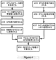
図4に示す流れ図を参照して、本発明の第2の態様の方法の実施例を示す。カウンタ206は、16ビットの連続アップカウンタであり、それは、計数が65、535の全計数から0に移行する時は常に、マーカ信号、この場合はパルスを段階401で生成する。このカウンタのクロック速度は、1MHzであり、従って、これらのパルスは、約65ms毎に発生する。パルスは、リンク207及び211を通じてGPS受信機208に供給されて(段階402)、ここでGPS受信機は、GPS時を測定する(段階403)。この場合に、GPS受信機は、パルスを期待するように事前準備されており、自己の内部クロックがGPS時(この例では世界時)に較正されるように完全な位置及び時間の解を計算している。リンク211を通じたマーカ信号パルスの到達により、現在のGPS時においてレジスタがラッチされ、この時間が読み出されて、時間タグとしてリンク209を通じてプロセッサ204に送り戻される(段階404)。
With reference to the flowchart shown in FIG. 4, an embodiment of the method of the second aspect of the present invention is shown.
一方、段階401から404までとは非同期的に、通信受信機201は、段階405でETSを受信して、リンク203を通じて対応するベースバンドI及びQサンプルをプロセッサ204に転送する。カウンタ206は、プロセッサ205に定期的に割り込みを行い、プロセッサは、カウンタ状態を対応するI及びQサンプルに関連付けることにより応答する。プログラムは、ETSテンプレートとの複素相互相関、及び次に補間を実行し、その結果、計算後に、プログラムは、サブカウント精度を有するカウンタに対するETSの到達のインスタントの値を有する(段階406)。この値は、段階407でソフトウエアプログラム210に転送される。
On the other hand, asynchronously with steps 401 to 404, the
ソフトウエアプログラム210は、ここで、式1を用いてETSのGPS時を計算することができる(段階408)。カウンタ206の速度は、正確に1MHzと仮定される。上述の最初の例のように、実際の周波数は、GPS受信機208によって測定されるカウンタ206からの2つの連続するマーカ信号、及びGPS時の差から推定されるカウンタ速度、及び1つのパルスと次のパルスの間のカウンタ状態の変化(この例では65、536)を用いて判断することができる。
The
本発明の方法はまた、衛星信号の取得又は再取得の支援のためにGPS受信機にGPS時を提供するのに使用することができる。この場合、ソフトウエアプログラム210は、上述のような最新の較正を実行したことから、又は他の場所から(例えば、ネットワーク101内のサーバから)送信される情報からETS信号のGPS時に対する較正を利用することができると仮定される。プロセッサは、次に、段階404でGPS受信機により供給されたGPS時間タグとETSの到達及び較正情報から計算されたGPS時との間の差を計算する付加的な段階409を行うことができる。これは、リンク211を通じてクロック誤差としてGPS受信機に供給することができる。このクロック誤差計算は、代わりにGPS受信機内部で実行することができる。この場合には、ETSの受信及び較正情報から計算された世界時がGPS受信機に供給される。
The method of the present invention can also be used to provide GPS time to a GPS receiver to assist in the acquisition or reacquisition of satellite signals. In this case, the
100 端末
101 GSM通信ネットワーク
102 使用中の送信基地局
105 衛星測位システム
100 terminal 101
Claims (22)
関連する世界時タグを有するマーカ信号をタイミングデバイスから取得する段階と、
前記マーカ信号と独立した発振器との間の時間又は位相関係を測定する段階と、
前記独立した発振器に対する識別された成分の到達時間情報を判断する段階と、
前記世界時タグ及び前記測定された時間又は位相関係から前記識別成分の前記到達時間情報に対応する世界時を計算する段階と、
前記計算された世界時を前記到達時間情報に関連付ける段階と、
を含むことを特徴とする方法。 A method for associating universal time with arrival time information of an identified component of a signal at a terminal of a wireless positioning system, comprising:
Obtaining from the timing device a marker signal having an associated universal time tag;
Measuring a time or phase relationship between the marker signal and an independent oscillator;
Determining arrival time information of identified components for the independent oscillator;
Calculating universal time corresponding to the arrival time information of the identification component from the universal time tag and the measured time or phase relationship;
Associating the calculated universal time with the arrival time information;
A method comprising the steps of:
独立した発振器からマーカ信号を取得する段階と、
前記マーカ信号に世界時タグを割り当てる段階と、
前記独立した発振器に対する識別された成分の到達時間情報を判断する段階と、
前記世界時タグ及び前記判断された相対到達時間情報から前記識別成分の前記到達時間情報に対応する世界時を計算する段階と、
前記計算された世界時を前記到達時間情報に関連付ける段階と、
を含むことを特徴とする方法。 A method for associating universal time with arrival time information of an identified component of a signal, comprising:
Obtaining a marker signal from an independent oscillator;
Assigning a universal time tag to the marker signal;
Determining arrival time information of identified components for the independent oscillator;
Calculating universal time corresponding to the arrival time information of the identification component from the universal time tag and the determined relative arrival time information;
Associating the calculated universal time with the arrival time information;
A method comprising the steps of:
推定到達時間情報における誤差を補正するために使用されることを特徴とする請求項1から請求項12のいずれか1項に記載の方法。 Two marker signals separated by an appropriate time interval, as well as their time tags, are supplied by the timing device, and then each difference in the independent oscillator phase or counter state calculates the oscillator frequency. The frequency of the oscillator used and calculated is
The method according to any one of claims 1 to 12, wherein the method is used to correct an error in the estimated arrival time information.
信号の世界時が既知であるマーカ信号を生成するためのタイミングデバイスと、
独立した発振器と、
前記タイミングデバイスから前記マーカ信号を取得し、該マーカ信号と前記独立発振器の間の時間又は位相関係を測定し、該発振器に対する識別成分の到達時間情報を判断し、前記世界時のタグ及び該測定された時間又は位相関係から該識別成分の該到達時間情報に対応する世界時を計算し、かつ該計算された世界時を該到達時間情報に関連付けるように配置されたプロセッサと、
を有することを特徴とする端末。 A wireless terminal of a wireless positioning system,
A timing device for generating a marker signal whose signal universal time is known;
An independent oscillator,
Obtaining the marker signal from the timing device, measuring a time or phase relationship between the marker signal and the independent oscillator, determining arrival time information of an identification component with respect to the oscillator, and measuring the universal time tag and the measurement A processor arranged to calculate a universal time corresponding to the arrival time information of the discriminating component from the calculated time or phase relationship and to associate the calculated universal time with the arrival time information;
A terminal characterized by comprising:
世界時タグを生成するタイミングデバイスと、
独立した発振器と、
前記独立した発振器からマーカ信号を取得し、該マーカ信号に前記世界時タグを割り当て、該発振器に対する識別成分の到達時間情報を判断し、該世界時タグ及び前記測定された時間又は位相関係から該識別成分の該到達時間情報に対応する世界時を計算し、かつ該計算された世界時を該到達時間情報に関連付けるように配置されたプロセッサと、
を有することを特徴とする端末。 A wireless terminal of a wireless positioning system,
A timing device that generates universal time tags,
An independent oscillator,
Obtaining a marker signal from the independent oscillator, assigning the universal time tag to the marker signal, determining arrival time information of an identification component for the oscillator, and determining the arrival time information of the identification component from the universal time tag and the measured time or phase relationship; A processor arranged to calculate a universal time corresponding to the arrival time information of an identification component and to associate the calculated universal time with the arrival time information;
A terminal characterized by comprising:
Applications Claiming Priority (2)
| Application Number | Priority Date | Filing Date | Title |
|---|---|---|---|
| EP06112194 | 2006-04-04 | ||
| PCT/EP2007/052371 WO2007113086A1 (en) | 2006-04-04 | 2007-03-13 | Associating a universal time with a received signal |
Publications (2)
| Publication Number | Publication Date |
|---|---|
| JP2009530625A true JP2009530625A (en) | 2009-08-27 |
| JP2009530625A5 JP2009530625A5 (en) | 2012-02-09 |
Family
ID=36928601
Family Applications (1)
| Application Number | Title | Priority Date | Filing Date |
|---|---|---|---|
| JP2009500821A Pending JP2009530625A (en) | 2006-04-04 | 2007-03-13 | How to associate universal time with a received signal |
Country Status (6)
| Country | Link |
|---|---|
| US (1) | US7978136B2 (en) |
| EP (1) | EP2002277B1 (en) |
| JP (1) | JP2009530625A (en) |
| AT (1) | ATE555399T1 (en) |
| TW (1) | TWI325061B (en) |
| WO (1) | WO2007113086A1 (en) |
Families Citing this family (29)
| Publication number | Priority date | Publication date | Assignee | Title |
|---|---|---|---|---|
| EP1901088A1 (en) * | 2006-09-18 | 2008-03-19 | Cambridge Positioning Systems Limited | Integrated mobile-terminal navigation |
| US8421675B2 (en) | 2006-12-07 | 2013-04-16 | Digimarc Corporation | Systems and methods for locating a mobile device within a cellular system |
| WO2008073347A1 (en) | 2006-12-07 | 2008-06-19 | Venture Ad Astra, Llc | Space-time calibration system and method |
| US8451763B2 (en) * | 2006-12-07 | 2013-05-28 | Digimarc Corporation | Wireless local area network-based position locating systems and methods |
| US9035829B2 (en) | 2008-09-10 | 2015-05-19 | Nextnav, Llc | Wide area positioning systems and methods |
| US9057606B2 (en) | 2009-09-10 | 2015-06-16 | Nextnav, Llc | Wide area positioning system |
| US8917209B2 (en) | 2009-09-10 | 2014-12-23 | Nextnav, Llc | Coding in a wide area positioning system (WAPS) |
| WO2010030825A1 (en) | 2008-09-10 | 2010-03-18 | Commlabs. Inc. | Wide area positioning system |
| US8086250B2 (en) * | 2009-02-03 | 2011-12-27 | Integrity Tracking, Llc | Communications method |
| US7983185B2 (en) | 2009-02-12 | 2011-07-19 | Zulutime, Llc | Systems and methods for space-time determinations with reduced network traffic |
| US9473963B2 (en) | 2009-05-27 | 2016-10-18 | Echo Ridge Llc | Interactive RF system testing system and method |
| US8521092B2 (en) | 2009-05-27 | 2013-08-27 | Echo Ridge Llc | Wireless transceiver test bed system and method |
| US9291712B2 (en) | 2009-09-10 | 2016-03-22 | Nextnav, Llc | Cell organization and transmission schemes in a wide area positioning system (WAPS) |
| US9372266B2 (en) | 2009-09-10 | 2016-06-21 | Nextnav, Llc | Cell organization and transmission schemes in a wide area positioning system (WAPS) |
| US8463290B2 (en) | 2010-07-09 | 2013-06-11 | Digimarc Corporation | Mobile device positioning in dynamic groupings of communication devices |
| US9588218B2 (en) | 2010-09-30 | 2017-03-07 | Echo Ridge Llc | System and method for robust navigation and geolocation using measurements of opportunity |
| US10212687B2 (en) | 2010-09-30 | 2019-02-19 | Echo Ridge Llc | System and method for robust navigation and geolocation using measurements of opportunity |
| US9176217B2 (en) | 2011-08-02 | 2015-11-03 | Nextnav, Llc | Cell organization and transmission schemes in a wide area positioning system (WAPS) |
| US8812019B2 (en) | 2011-08-05 | 2014-08-19 | Qualcomm Incorporated | Providing wireless transmitter almanac information to mobile device based on expected route |
| US9594170B2 (en) | 2011-09-30 | 2017-03-14 | Echo Ridge Llc | Performance improvements for measurement of opportunity geolocation/navigation systems |
| US9739891B2 (en) | 2011-09-30 | 2017-08-22 | Echo Ridge Llc | System and method of using measurements of opportunity with vector tracking filters for improved navigation |
| US9148808B2 (en) | 2011-12-01 | 2015-09-29 | Echo Ridge Llc | Adaptive RF system testing system and method |
| US9167542B2 (en) | 2012-03-12 | 2015-10-20 | Qualcomm Incorporated | Determining clock models |
| US9282471B2 (en) | 2012-03-21 | 2016-03-08 | Digimarc Corporation | Positioning systems for wireless networks |
| WO2013184701A1 (en) | 2012-06-05 | 2013-12-12 | Arun Raghupathy | Systems and methods for location positioning of user device |
| US9286490B2 (en) | 2013-09-10 | 2016-03-15 | Nextnav, Llc | Systems and methods for providing conditional access to transmitted information |
| US9390279B2 (en) | 2012-09-11 | 2016-07-12 | Nextnav, Llc | Systems and methods for providing conditional access to transmitted information |
| US10149261B2 (en) | 2013-11-04 | 2018-12-04 | Qualcomm Incorporated | Methods and systems for mobile device clock management |
| US10338201B2 (en) | 2015-09-17 | 2019-07-02 | Qualcomm Incorporated | Timing synchronization of LIDAR system to reduce interference |
Citations (1)
| Publication number | Priority date | Publication date | Assignee | Title |
|---|---|---|---|---|
| JP2002318276A (en) * | 2001-02-05 | 2002-10-31 | Nokia Corp | Method, apparatus, and system for gps time synchronization using cellular signal burst |
Family Cites Families (26)
| Publication number | Priority date | Publication date | Assignee | Title |
|---|---|---|---|---|
| US4754465A (en) * | 1984-05-07 | 1988-06-28 | Trimble Navigation, Inc. | Global positioning system course acquisition code receiver |
| EP0303371B1 (en) | 1987-08-10 | 1993-03-10 | Lynxvale Limited | Navigation and tracking system |
| US5225842A (en) | 1991-05-09 | 1993-07-06 | Navsys Corporation | Vehicle tracking system employing global positioning system (gps) satellites |
| US5365516A (en) | 1991-08-16 | 1994-11-15 | Pinpoint Communications, Inc. | Communication system and method for determining the location of a transponder unit |
| US5717406A (en) | 1995-06-07 | 1998-02-10 | Sanconix Inc. | Enhanced position calculation |
| GB9519087D0 (en) | 1995-09-19 | 1995-11-22 | Cursor Positioning Sys Ltd | Navigation and tracking system |
| US5841396A (en) * | 1996-03-08 | 1998-11-24 | Snaptrack, Inc. | GPS receiver utilizing a communication link |
| US5945944A (en) | 1996-03-08 | 1999-08-31 | Snaptrack, Inc. | Method and apparatus for determining time for GPS receivers |
| US5663735A (en) | 1996-05-20 | 1997-09-02 | Trimble Navigation Limited | GPS receiver using a radio signal for improving time to first fix |
| FI103468B (en) | 1996-08-30 | 1999-06-30 | Nokia Telecommunications Oy | Limitation of the mobility of a subscriber terminal in a radio system |
| US5812087A (en) * | 1997-02-03 | 1998-09-22 | Snaptrack, Inc. | Method and apparatus for satellite positioning system based time measurement |
| US6353412B1 (en) | 1998-03-17 | 2002-03-05 | Qualcomm, Incorporated | Method and apparatus for determining position location using reduced number of GPS satellites and synchronized and unsynchronized base stations |
| US6429815B1 (en) | 1998-03-17 | 2002-08-06 | Qualcomm, Incorporated | Method and apparatus for determining search center and size in searches for GPS transmissions |
| US6081229A (en) | 1998-03-17 | 2000-06-27 | Qualcomm Incorporated | System and method for determining the position of a wireless CDMA transceiver |
| GB9912724D0 (en) | 1999-06-01 | 1999-08-04 | Cambridge Positioning Sys Ltd | Radio positioning system |
| US6603978B1 (en) | 2000-03-24 | 2003-08-05 | Ericsson Inc. | Accurate GPS time estimate based on information from a wireless communications system |
| AU2001249449A1 (en) * | 2000-03-30 | 2001-10-15 | Cellguide Ltd. | Providing time synchronization to a gps locator |
| US6665541B1 (en) * | 2000-05-04 | 2003-12-16 | Snaptrack, Incorporated | Methods and apparatuses for using mobile GPS receivers to synchronize basestations in cellular networks |
| US7369599B2 (en) | 2000-12-18 | 2008-05-06 | Qualcomm Incorporated | Method and apparatus for reducing code phase search space |
| JP3721964B2 (en) * | 2000-09-12 | 2005-11-30 | 三菱電機株式会社 | GPS receiver |
| US6445927B1 (en) | 2000-09-18 | 2002-09-03 | Motorola, Inc. | Method and apparatus for calibrating base station locations and perceived time bias offsets in an assisted GPS transceiver |
| US7254402B2 (en) | 2000-10-12 | 2007-08-07 | Qualcomm Incorporated | GPS satellite signal acquisition assistance system and method in a wireless communications network |
| US6778885B2 (en) | 2000-10-16 | 2004-08-17 | Qualcomm Inc. | Apparatus, method, and system of transferring correction information |
| US6865380B2 (en) | 2001-02-05 | 2005-03-08 | Nokia Corporation | Method, apparatus and system for frequency stabilization using cellular signal bursts |
| KR100898530B1 (en) | 2001-03-15 | 2009-05-20 | 퀄컴 인코포레이티드 | Time acquisition in a wireless position determination system |
| US20020193108A1 (en) | 2001-05-10 | 2002-12-19 | Robinett Robert L. | Multi-mode satellite and terrestrial communication device with position location |
-
2007
- 2007-03-13 WO PCT/EP2007/052371 patent/WO2007113086A1/en active Application Filing
- 2007-03-13 US US12/225,860 patent/US7978136B2/en active Active
- 2007-03-13 AT AT07712519T patent/ATE555399T1/en active
- 2007-03-13 JP JP2009500821A patent/JP2009530625A/en active Pending
- 2007-03-13 EP EP07712519A patent/EP2002277B1/en active Active
- 2007-03-21 TW TW096109779A patent/TWI325061B/en not_active IP Right Cessation
Patent Citations (1)
| Publication number | Priority date | Publication date | Assignee | Title |
|---|---|---|---|---|
| JP2002318276A (en) * | 2001-02-05 | 2002-10-31 | Nokia Corp | Method, apparatus, and system for gps time synchronization using cellular signal burst |
Also Published As
| Publication number | Publication date |
|---|---|
| TWI325061B (en) | 2010-05-21 |
| US20090273518A1 (en) | 2009-11-05 |
| WO2007113086A1 (en) | 2007-10-11 |
| US7978136B2 (en) | 2011-07-12 |
| EP2002277B1 (en) | 2012-04-25 |
| EP2002277A1 (en) | 2008-12-17 |
| TW200807008A (en) | 2008-02-01 |
| ATE555399T1 (en) | 2012-05-15 |
Similar Documents
| Publication | Publication Date | Title |
|---|---|---|
| JP2009530625A (en) | How to associate universal time with a received signal | |
| US8253628B2 (en) | Transfer of calibrated time information in a mobile terminal | |
| KR100976752B1 (en) | Method, apparatus and system for synchronizing a cellular communication system to GPS time | |
| US6678510B2 (en) | Method, apparatus and system for GPS time synchronization using cellular signal bursts | |
| US7925278B2 (en) | Method and system for locating a wireless device in a wireless communication network | |
| US7327310B2 (en) | Method and apparatus for managing time in a satellite positioning system | |
| US7236126B2 (en) | AGPS system using NTP server and method for determining the location of a terminal using a NTP server | |
| US9182493B2 (en) | Fine time assistance for global navigation satellite systems | |
| US20090146871A1 (en) | Method and apparatus for managing time in a satellite positioning system | |
| JP2004279409A (en) | Positioning system | |
| KR100881869B1 (en) | Methods and apparatuses for using mobile gps stations to synchronize basestations | |
| KR20010051654A (en) | A method of timing calibration | |
| JP2001183438A (en) | Timing calibration method | |
| KR101099175B1 (en) | Transfer of calibrated time information in a mobile terminal | |
| KR20040008971A (en) | Apparatus and method for measuring information to support location service in universal mobile telecommunication system |
Legal Events
| Date | Code | Title | Description |
|---|---|---|---|
| A131 | Notification of reasons for refusal |
Free format text: JAPANESE INTERMEDIATE CODE: A131 Effective date: 20110912 |
|
| A521 | Request for written amendment filed |
Free format text: JAPANESE INTERMEDIATE CODE: A523 Effective date: 20111209 |
|
| A524 | Written submission of copy of amendment under article 19 pct |
Free format text: JAPANESE INTERMEDIATE CODE: A524 Effective date: 20111209 |
|
| A131 | Notification of reasons for refusal |
Free format text: JAPANESE INTERMEDIATE CODE: A131 Effective date: 20120918 |
|
| A02 | Decision of refusal |
Free format text: JAPANESE INTERMEDIATE CODE: A02 Effective date: 20130304 |