JP2009529845A - Method and apparatus for encoding moving picture by adaptively applying optimal prediction mode, and method and apparatus for decoding moving picture - Google Patents
Method and apparatus for encoding moving picture by adaptively applying optimal prediction mode, and method and apparatus for decoding moving picture Download PDFInfo
- Publication number
- JP2009529845A JP2009529845A JP2009500288A JP2009500288A JP2009529845A JP 2009529845 A JP2009529845 A JP 2009529845A JP 2009500288 A JP2009500288 A JP 2009500288A JP 2009500288 A JP2009500288 A JP 2009500288A JP 2009529845 A JP2009529845 A JP 2009529845A
- Authority
- JP
- Japan
- Prior art keywords
- image
- component
- prediction
- block
- prediction mode
- Prior art date
- Legal status (The legal status is an assumption and is not a legal conclusion. Google has not performed a legal analysis and makes no representation as to the accuracy of the status listed.)
- Pending
Links
Images


Classifications
-
- H—ELECTRICITY
- H04—ELECTRIC COMMUNICATION TECHNIQUE
- H04N—PICTORIAL COMMUNICATION, e.g. TELEVISION
- H04N19/00—Methods or arrangements for coding, decoding, compressing or decompressing digital video signals
- H04N19/10—Methods or arrangements for coding, decoding, compressing or decompressing digital video signals using adaptive coding
- H04N19/102—Methods or arrangements for coding, decoding, compressing or decompressing digital video signals using adaptive coding characterised by the element, parameter or selection affected or controlled by the adaptive coding
- H04N19/103—Selection of coding mode or of prediction mode
-
- H—ELECTRICITY
- H04—ELECTRIC COMMUNICATION TECHNIQUE
- H04N—PICTORIAL COMMUNICATION, e.g. TELEVISION
- H04N19/00—Methods or arrangements for coding, decoding, compressing or decompressing digital video signals
- H04N19/10—Methods or arrangements for coding, decoding, compressing or decompressing digital video signals using adaptive coding
- H04N19/134—Methods or arrangements for coding, decoding, compressing or decompressing digital video signals using adaptive coding characterised by the element, parameter or criterion affecting or controlling the adaptive coding
- H04N19/136—Incoming video signal characteristics or properties
-
- G—PHYSICS
- G06—COMPUTING; CALCULATING OR COUNTING
- G06T—IMAGE DATA PROCESSING OR GENERATION, IN GENERAL
- G06T9/00—Image coding
- G06T9/007—Transform coding, e.g. discrete cosine transform
-
- H—ELECTRICITY
- H04—ELECTRIC COMMUNICATION TECHNIQUE
- H04N—PICTORIAL COMMUNICATION, e.g. TELEVISION
- H04N19/00—Methods or arrangements for coding, decoding, compressing or decompressing digital video signals
- H04N19/10—Methods or arrangements for coding, decoding, compressing or decompressing digital video signals using adaptive coding
- H04N19/102—Methods or arrangements for coding, decoding, compressing or decompressing digital video signals using adaptive coding characterised by the element, parameter or selection affected or controlled by the adaptive coding
- H04N19/103—Selection of coding mode or of prediction mode
- H04N19/109—Selection of coding mode or of prediction mode among a plurality of temporal predictive coding modes
-
- H—ELECTRICITY
- H04—ELECTRIC COMMUNICATION TECHNIQUE
- H04N—PICTORIAL COMMUNICATION, e.g. TELEVISION
- H04N19/00—Methods or arrangements for coding, decoding, compressing or decompressing digital video signals
- H04N19/10—Methods or arrangements for coding, decoding, compressing or decompressing digital video signals using adaptive coding
- H04N19/102—Methods or arrangements for coding, decoding, compressing or decompressing digital video signals using adaptive coding characterised by the element, parameter or selection affected or controlled by the adaptive coding
- H04N19/103—Selection of coding mode or of prediction mode
- H04N19/11—Selection of coding mode or of prediction mode among a plurality of spatial predictive coding modes
-
- H—ELECTRICITY
- H04—ELECTRIC COMMUNICATION TECHNIQUE
- H04N—PICTORIAL COMMUNICATION, e.g. TELEVISION
- H04N19/00—Methods or arrangements for coding, decoding, compressing or decompressing digital video signals
- H04N19/10—Methods or arrangements for coding, decoding, compressing or decompressing digital video signals using adaptive coding
- H04N19/134—Methods or arrangements for coding, decoding, compressing or decompressing digital video signals using adaptive coding characterised by the element, parameter or criterion affecting or controlling the adaptive coding
- H04N19/146—Data rate or code amount at the encoder output
- H04N19/147—Data rate or code amount at the encoder output according to rate distortion criteria
-
- H—ELECTRICITY
- H04—ELECTRIC COMMUNICATION TECHNIQUE
- H04N—PICTORIAL COMMUNICATION, e.g. TELEVISION
- H04N19/00—Methods or arrangements for coding, decoding, compressing or decompressing digital video signals
- H04N19/10—Methods or arrangements for coding, decoding, compressing or decompressing digital video signals using adaptive coding
- H04N19/134—Methods or arrangements for coding, decoding, compressing or decompressing digital video signals using adaptive coding characterised by the element, parameter or criterion affecting or controlling the adaptive coding
- H04N19/146—Data rate or code amount at the encoder output
- H04N19/15—Data rate or code amount at the encoder output by monitoring actual compressed data size at the memory before deciding storage at the transmission buffer
-
- H—ELECTRICITY
- H04—ELECTRIC COMMUNICATION TECHNIQUE
- H04N—PICTORIAL COMMUNICATION, e.g. TELEVISION
- H04N19/00—Methods or arrangements for coding, decoding, compressing or decompressing digital video signals
- H04N19/10—Methods or arrangements for coding, decoding, compressing or decompressing digital video signals using adaptive coding
- H04N19/169—Methods or arrangements for coding, decoding, compressing or decompressing digital video signals using adaptive coding characterised by the coding unit, i.e. the structural portion or semantic portion of the video signal being the object or the subject of the adaptive coding
- H04N19/17—Methods or arrangements for coding, decoding, compressing or decompressing digital video signals using adaptive coding characterised by the coding unit, i.e. the structural portion or semantic portion of the video signal being the object or the subject of the adaptive coding the unit being an image region, e.g. an object
- H04N19/176—Methods or arrangements for coding, decoding, compressing or decompressing digital video signals using adaptive coding characterised by the coding unit, i.e. the structural portion or semantic portion of the video signal being the object or the subject of the adaptive coding the unit being an image region, e.g. an object the region being a block, e.g. a macroblock
-
- H—ELECTRICITY
- H04—ELECTRIC COMMUNICATION TECHNIQUE
- H04N—PICTORIAL COMMUNICATION, e.g. TELEVISION
- H04N19/00—Methods or arrangements for coding, decoding, compressing or decompressing digital video signals
- H04N19/10—Methods or arrangements for coding, decoding, compressing or decompressing digital video signals using adaptive coding
- H04N19/169—Methods or arrangements for coding, decoding, compressing or decompressing digital video signals using adaptive coding characterised by the coding unit, i.e. the structural portion or semantic portion of the video signal being the object or the subject of the adaptive coding
- H04N19/186—Methods or arrangements for coding, decoding, compressing or decompressing digital video signals using adaptive coding characterised by the coding unit, i.e. the structural portion or semantic portion of the video signal being the object or the subject of the adaptive coding the unit being a colour or a chrominance component
-
- H—ELECTRICITY
- H04—ELECTRIC COMMUNICATION TECHNIQUE
- H04N—PICTORIAL COMMUNICATION, e.g. TELEVISION
- H04N19/00—Methods or arrangements for coding, decoding, compressing or decompressing digital video signals
- H04N19/10—Methods or arrangements for coding, decoding, compressing or decompressing digital video signals using adaptive coding
- H04N19/189—Methods or arrangements for coding, decoding, compressing or decompressing digital video signals using adaptive coding characterised by the adaptation method, adaptation tool or adaptation type used for the adaptive coding
- H04N19/19—Methods or arrangements for coding, decoding, compressing or decompressing digital video signals using adaptive coding characterised by the adaptation method, adaptation tool or adaptation type used for the adaptive coding using optimisation based on Lagrange multipliers
-
- H—ELECTRICITY
- H04—ELECTRIC COMMUNICATION TECHNIQUE
- H04N—PICTORIAL COMMUNICATION, e.g. TELEVISION
- H04N19/00—Methods or arrangements for coding, decoding, compressing or decompressing digital video signals
- H04N19/50—Methods or arrangements for coding, decoding, compressing or decompressing digital video signals using predictive coding
- H04N19/593—Methods or arrangements for coding, decoding, compressing or decompressing digital video signals using predictive coding involving spatial prediction techniques
-
- H—ELECTRICITY
- H04—ELECTRIC COMMUNICATION TECHNIQUE
- H04N—PICTORIAL COMMUNICATION, e.g. TELEVISION
- H04N19/00—Methods or arrangements for coding, decoding, compressing or decompressing digital video signals
- H04N19/60—Methods or arrangements for coding, decoding, compressing or decompressing digital video signals using transform coding
- H04N19/61—Methods or arrangements for coding, decoding, compressing or decompressing digital video signals using transform coding in combination with predictive coding
Abstract
動画を符号化する方法及び装置、動画を復号化する方法及び装置に係り、所定画像の特性に基づいて、現在画像の色成分のそれぞれのマクロブロック別に色成分のそれぞれのブロックに最適の予測モードを選択し、この予測モードによって現在画像に対する予測画像を生成し、この予測画像を利用して動画の符号化を行うように、色成分のそれぞれのマクロブロックに最適の予測モードを適応的に適用することによって、動画の符号化及び復号化効率を高めうる。
The present invention relates to a method and apparatus for encoding a moving image and a method and apparatus for decoding a moving image, and based on the characteristics of a predetermined image, an optimal prediction mode for each block of the color component for each macroblock of the color component of the current image The prediction mode for the current image is generated by this prediction mode, and the optimal prediction mode is adaptively applied to each macroblock of the color components so that the video is encoded using this prediction image. By doing so, the encoding and decoding efficiency of a moving image can be improved.
Description
本発明は、動画を符号化する方法及び装置、動画を復号化する方法及び装置に係り、特に、H.264/MPEG−4 AVC(Advanced Video Coding)FRExt(Fidelity Range Extensions)標準分野における動画を符号化する方法及び装置、動画を復号化する方法及び装置に関する。 The present invention relates to a method and apparatus for encoding a moving image and a method and apparatus for decoding a moving image, and more particularly, to a moving image in a standard field of H.264 / MPEG-4 AVC (Advanced Video Coding) FRExt (Fidelity Range Extensions). The present invention relates to a method and apparatus for encoding, and a method and apparatus for decoding a moving image.
“レジデュアル色変換”と呼ばれる新たなRGB符号化技術は、H.264/MPEG−4 AVC FRExt標準化過程で開発された。これは、RGB色空間をYCbCr色空間に変換する時に発生する画質の劣化を防止するためのものである。しかし、H.264/MPEG−4 AVC FRExt上のRGB符号化及び復号化技術も、動画再生機器に適用するにはまだ動画の符号化及び復号化効率が十分に高くないという問題点があった。 A new RGB encoding technique called “residual color conversion” was developed during the H.264 / MPEG-4 AVC FRext standardization process. This is to prevent image quality degradation that occurs when the RGB color space is converted to the YCbCr color space. However, the RGB encoding and decoding technology on H.264 / MPEG-4 AVC FRExt also has a problem that the encoding and decoding efficiency of moving images is not yet high enough to be applied to moving image playback devices. .
本発明が解決しようとする技術的課題は、H.264/MPEG−4 AVC FRExt上のRGB符号化技術の動画符号化及び復号化効率を高めうる装置及び方法を提供することである。 The technical problem to be solved by the present invention is to provide an apparatus and method capable of improving the moving picture coding and decoding efficiency of the RGB coding technique on H.264 / MPEG-4 AVC FRExt.
また、前記の方法をコンピュータで実行させるためのプログラムを記録したコンピュータで読み取り可能な記録媒体を提供することである。 Another object of the present invention is to provide a computer-readable recording medium on which a program for causing the computer to execute the method is recorded.
前記課題を解決するための本発明による符号化装置における予測画像の生成方法は、所定画像の特性に基づいて、現在画像の色成分のそれぞれのブロック別に前記色成分のそれぞれのブロックに最適の予測モードを選択するステップと、前記選択された予測モードによって、前記現在画像に対する予測画像を生成するステップと、を含む。 A method for generating a predicted image in an encoding apparatus according to the present invention for solving the above-described problem is based on characteristics of a predetermined image, and optimal prediction is performed for each block of the color component for each block of the color component of the current image. Selecting a mode; and generating a predicted image for the current image according to the selected prediction mode.
前記他の課題を解決するために、本発明は、前記の符号化装置における予測画像の生成方法をコンピュータで実行させるためのプログラムを記録したコンピュータで読み取り可能な記録媒体を提供する。 In order to solve the other problems, the present invention provides a computer-readable recording medium recording a program for causing a computer to execute a predicted image generation method in the encoding device.
前記さらに他の課題を解決するための本発明による符号化装置における予測画像生成装置は、所定画像の特性に基づいて、現在画像の色成分のそれぞれのブロック別に前記色成分のそれぞれのブロックに最適の予測モードを選択する選択部と、前記選択された予測モードによって、前記現在画像に対する予測画像を生成する生成部と、を備える。 According to another aspect of the present invention, there is provided a predictive image generation apparatus that is optimal for each block of color components for each block of color components of a current image based on characteristics of a predetermined image. A selection unit that selects the prediction mode, and a generation unit that generates a prediction image for the current image according to the selected prediction mode.
前記さらに他の課題を解決するための本発明による符号化方法は、所定画像の特性に基づいて、現在画像の色成分のそれぞれのブロック別に前記色成分のそれぞれのブロックに最適の予測モードを選択するステップと、前記選択された予測モードによって、前記現在画像に対する予測画像を生成するステップと、前記現在画像と前記予測画像との差に該当する色成分のそれぞれのレジデューを生成するステップと、前記生成されたレジデューを符号化することによってビットストリームを生成するステップと、を含む。 According to another aspect of the present invention, there is provided an encoding method that selects an optimum prediction mode for each block of the color component for each block of the color component of a current image based on characteristics of a predetermined image. Generating a predicted image for the current image according to the selected prediction mode; generating a respective residue of color components corresponding to a difference between the current image and the predicted image; Generating a bitstream by encoding the generated residue.
前記さらに他の課題を解決するために、本発明は、前記の符号化方法をコンピュータで実行させるためのプログラムを記録したコンピュータで読み取り可能な記録媒体を提供する。 In order to solve the further another problem, the present invention provides a computer-readable recording medium in which a program for causing a computer to execute the encoding method is recorded.
前記さらに他の課題を解決するための本発明による符号化装置は、所定画像の特性に基づいて、現在画像の色成分のそれぞれのブロック別に前記色成分のそれぞれのブロックに最適の予測モードを選択する選択部と、前記選択された予測モードによって前記現在画像に対する予測画像を生成し、前記現在画像と前記予測画像との差に該当する色成分のそれぞれのレジデューを生成する生成部と、前記生成されたレジデューを符号化することによって、ビットストリームを生成する符号化部と、を備える。 According to another aspect of the present invention, there is provided an encoding apparatus that selects an optimum prediction mode for each block of color components for each block of color components of a current image based on characteristics of a predetermined image. A generating unit that generates a predicted image for the current image according to the selected prediction mode, and generates a respective color component corresponding to a difference between the current image and the predicted image, and the generation An encoding unit that generates a bitstream by encoding the generated residue.
前記さらに他の課題を解決するための本発明による復号化装置における予測画像の生成方法は、ビットストリームを復号化することによって、現在画像の色成分のそれぞれのブロックに最適の予測モードを表す情報を復元するステップと、前記復元された情報が表す予測モードによって、前記現在画像に対する予測画像を生成するステップと、を含む。 According to another aspect of the present invention, there is provided a decoding method for generating a prediction image in a decoding apparatus according to the present invention, wherein information representing a prediction mode optimum for each block of color components of a current image is obtained by decoding a bitstream. And a step of generating a predicted image for the current image according to a prediction mode represented by the recovered information.
前記さらに他の課題を解決するために、本発明は、前記の復号化装置における予測画像の生成方法をコンピュータで実行させるためのプログラムを記録したコンピュータで読み取り可能な記録媒体を提供する。 In order to solve the further another problem, the present invention provides a computer-readable recording medium storing a program for causing a computer to execute the predicted image generation method in the decoding apparatus.
前記さらに他の課題を解決するための本発明による復号化装置における予測画像生成装置は、ビットストリームを復号化することによって、現在画像の色成分のそれぞれのブロックに最適の予測モードを表す情報を復元する復号化部と、前記復元された情報が表す予測モードによって、前記現在画像に対する予測画像を生成する生成部と、を備える。 The predictive image generation apparatus in the decoding apparatus according to the present invention for solving the further another problem described above decodes a bitstream to obtain information indicating an optimal prediction mode for each block of color components of the current image. A decoding unit for restoring, and a generating unit for generating a predicted image for the current image according to a prediction mode represented by the restored information.
前記さらに他の課題を解決するための本発明による復号化方法は、ビットストリームを復号化することによって、現在画像の色成分のそれぞれのブロックに最適の予測モードを表す情報を復元するステップと、前記復元された情報が表す予測モードによって、前記現在画像と前記現在画像に対する予測画像との差に該当するレジデューを生成するステップと、前記復元された情報が表す予測モードによって、前記予測画像を生成するステップと、前記生成されたレジデューと前記生成された予測画面との合算に該当する復元画面を生成するステップと、を含む。 The decoding method according to the present invention for solving the above-described further problem includes a step of restoring information representing a prediction mode optimal for each block of color components of a current image by decoding a bitstream; Generating a prediction corresponding to a difference between the current image and a predicted image with respect to the current image according to a prediction mode represented by the restored information; and generating the predicted image according to a prediction mode represented by the restored information. And a step of generating a restoration screen corresponding to the sum of the generated residue and the generated prediction screen.
前記さらに他の課題を解決するために、本発明は、前記の復号化方法をコンピュータで実行させるためのプログラムを記録したコンピュータで読み取り可能な記録媒体を提供する。 In order to solve the further another problem, the present invention provides a computer-readable recording medium storing a program for causing the computer to execute the decoding method.
前記さらに他の課題を解決するための本発明による復号化装置は、ビットストリームを復号化することによって、現在画像の色成分のそれぞれのブロックに最適の予測モードを表す情報を復元する復号化部と、前記復元された情報が表す予測モードによって、前記予測画像を生成する第1生成部と、前記復元された情報が表す予測モードによって、前記現在画像と前記現在画像に対する予測画像との差に該当するレジデューを生成し、前記生成されたレジデューと前記生成された予測画面との合算に該当する復元画面を生成する第2生成部と、を備える。 The decoding apparatus according to the present invention for solving the further another problem is a decoding unit that decodes a bitstream to restore information representing a prediction mode optimum for each block of color components of a current image. A difference between the current image and the predicted image for the current image according to the first generation unit that generates the predicted image according to the prediction mode represented by the restored information, and the prediction mode represented by the restored information. A second generation unit that generates a corresponding residue and generates a restoration screen corresponding to a sum of the generated residue and the generated prediction screen;
本発明によれば、現在画像の色成分のそれぞれのマクロブロック別に色成分のそれぞれのマクロブロックに最適の予測モードを適応的に適用して動画の符号化及び復号化を行うことによって、動画の符号化及び復号化効率を高めうる。特に、現在画像の色成分のそれぞれのマクロブロック別に、単一予測モード、複合予測モード、インター予測、イントラ予測、レジデュー変換、RCT(Residual Color Transformation)変換、IPP(Inter−Plane Prediction)変換、RCP(Residual Color Prediction)変換などの多様な符号化方式を選択的に適用することによって、動画の符号化及び復号化効率を極大化させうる。 According to the present invention, by encoding and decoding a moving image by adaptively applying an optimal prediction mode to each macroblock of the color component for each macroblock of the color component of the current image, Encoding and decoding efficiency can be improved. In particular, for each macroblock of the color component of the current image, single prediction mode, composite prediction mode, inter prediction, intra prediction, residue conversion, RCT (Residual Color Transformation) conversion, IPP (Inter-Plane Prediction) conversion, RCP By selectively applying various encoding methods such as (Residual Color Prediction) conversion, the encoding and decoding efficiency of a moving image can be maximized.
以下、図面を参照して、本発明の望ましい実施形態を詳細に説明する。特に、以下の実施形態で、現在画像は、現在の動画符号化及び復号化の対象となる画像を意味し、参照画像は、現在画像の符号化または復号化に参照される画像を意味する。一般的に、参照画像は、現在画像の過去画像であるが、現在画像の未来画像となってもよく、複数の画像となってもよい。 Hereinafter, preferred embodiments of the present invention will be described in detail with reference to the drawings. In particular, in the following embodiments, a current image means an image that is a current moving image encoding and decoding target, and a reference image means an image that is referred to for encoding or decoding the current image. In general, the reference image is a past image of the current image, but it may be a future image of the current image or a plurality of images.
図1は、本発明の望ましい一実施形態による動画符号化装置の構成図である。図1を参照するに、本実施形態による動画符号化装置は、最適モード選択部110、レジデュー生成部120、周波数空間変換部130、量子化部400、エントロピー符号化部150、逆量子化部160、周波数空間逆変換部170、及び復元画像生成部180で構成される。
FIG. 1 is a block diagram of a moving picture encoding apparatus according to an exemplary embodiment of the present invention. Referring to FIG. 1, the moving picture coding apparatus according to the present embodiment includes an optimum
最適モード選択部110は、サンプル画像の特性に基づいて、現在画像の色成分のそれぞれのマクロブロック別に色成分のそれぞれのマクロブロックに最適の予測モードを選択する。ここで、色成分のそれぞれのマクロブロックは、相互対応するマクロブロックということを、当業者ならば理解できる。
The optimum
例えば、最適モード選択部110は、現在画像の色成分のそれぞれのマクロブロックに最適である予測モードとして、現在画像の色成分のそれぞれのマクロブロックに一律的に適用される予測モード(以下、“単一予測モード”という)及び現在画像の色成分のそれぞれのマクロブロックに独立的に適用される予測モード(以下、“複合予測モード”)のうち何れか一つを選択しうる。
For example, the optimal
また、最適モード選択部110は、現在画像の色成分のそれぞれのマクロブロックに、最適の予測モードとして単一予測モード及び複合予測モードのうち何れか一つを選択し、これらのうち単一予測モードを選択した場合に、色成分のそれぞれの第1レジデュー間の差に該当する第2レジデューを生成する予測モード(以下、“レジデュー変換モード”という)を選択することもある。
Further, the optimal
また、最適モード選択部110は、現在画像の色成分のそれぞれのマクロブロックに、最適の予測モードとして単一予測モード及び複合予測モードのうち何れか一つを選択し、これらのうち単一予測モードを選択した場合に、RCT(Residual Color Transformation)変換を行う予測モード(以下、“RCT変換モード”という)、IPP(Inter−Plane Prediction)変換を行うモード(以下、“IPP変換モード”という)、及びRCP(Residual Color Prediction)変換を行う予測モード(以下、“RCP変換モード”という)のうち何れか一つを選択することもある。RCT変換、IPP変換、RCP変換については後述する。
Further, the optimal
本実施形態で、サンプル画像としては、現在画像の以前画像のうち何れか一つが使われる。最適モード選択部110は、サンプル画像の色成分のそれぞれのマクロブロックに最適の予測モードを選択するために、このサンプル画像に対して全ての可能な予測モードを一つずつ順次に選択し、選択された予測モードによって符号化された全ての結果を比較して、多数の予測モードのうち、このサンプル画像の色成分のそれぞれのマクロブロックに最適の予測モードを選択する。以後、この予測モードが現在画像の色成分のそれぞれのマクロブロックに最適の予測モードとして使われる。
In the present embodiment, any one of the previous images of the current image is used as the sample image. The optimal
さらに詳細に説明すれば、最適モード選択部110は、現在画像の色成分のそれぞれのマクロブロックに最適である予測モードとして、サンプル画像を符号化した結果に該当するビットストリームの量及びサンプル画像とこのサンプル画像の復元画像との間の画質の歪曲が最も少ない予測モードを選択する。下記のものを参照するに、サンプル画像を符号化した結果に該当するビットストリームの量は、エントロピー符号化部150によって生成されたビットストリームの量となり、サンプル画像の復元画像は、復元画像生成部180によって生成された復元画像となる。
In more detail, the optimum
特に、本実施形態によれば、最適モード選択部110は、ラグランジアン最適化技法を使用して最適モードを選択する。すなわち、最適モード選択部110は、次の式(1)を利用して、原本画像と復元画像との差値を乗算して合算した値の平均から画質の歪曲を算出する。
In particular, according to the present embodiment, the optimal

また、最適モード選択部110は、次の式(2)を利用して画質の歪曲の程度とビットストリームの量のそれぞれの単位との差を調整するために、一定定数“λ”とビットストリームの量“R”とを積算し、この積算値と画質の歪曲の程度“D”とを合算することによって、現在画像の色成分のそれぞれのマクロブロックに最適の予測モードを選択するための最終値“L”を算出する。
Further, the optimal
前記のラグランジアン最適化技法によって実験を行えば、最適モード選択部110は、サンプル画像の色成分のそれぞれの類似性が高い場合には、単一予測モードを選択し、サンプル画像の色成分間の類似性が低い場合には、複合予測モードを選択する。
If an experiment is performed using the Lagrangian optimization technique, the optimal
レジデュー生成部120は、最適モード選択部110によって選択された予測モードによって、色成分のそれぞれのマクロブロック別に現在画像に対する予測画像を生成し、現在画像と予測画像との差に該当するレジデューを生成する。そうでなければ、レジデュー生成部120は、最適モード選択部110によって選択された予測モードによって、色成分のそれぞれのマクロブロック別に現在画像に対する予測画像を生成し、現在画像と予測画像との差に該当する第1レジデューを生成し、色成分のそれぞれのマクロブロック別に第1レジデューの差に該当する第2レジデューを生成する。
The
周波数空間変換部130は、レジデュー生成部120によって生成されたレジデューを色空間から周波数空間に変換する。そうでなければ、周波数空間変換部130は、レジデュー生成部120によって生成された第2レジデューを色空間から周波数空間に変換する。H.264/MPEG−4 AVCでは、色空間から周波数空間に変換する方式としてDHT(Discrete Hadamard Transformation)、DCT(Discrete Cosine Transformation)基盤の整数変換が導入された。
The frequency
量子化部140は、周波数空間変換部130によって変換された値を量子化する。すなわち、量子化部140は、周波数空間変換部130によって変換された結果である周波数成分値を量子化パラメータで割って、その結果を整数値に近似化する。
The
エントロピー符号化部150は、量子化部140によって量子化された値をエントロピー符号化することによってビットストリームを生成し、これを出力する。特に、本実施形態によれば、エントロピー符号化部150は、動画符号化装置によって使われた予測モード、すなわち、最適モード選択部110によって選択された予測モードを表す情報も共にエントロピー符号化することによって、これを含むビットストリームを生成する。H.264/MPEG−4 AVCでは、エントロピー符号化方式でCAVLC(Context−Adaptive Variable Length Coding)、CABAC(Context−Adaptive Binary Arithmetic Coding)が導入された。
The
さらに詳細に説明すれば、エントロピー符号化部150は、現在画像の色成分のそれぞれのマクロブロック別に、マクロブロックヘッダに最適モード選択部110によって選択された予測モードを表す情報を含むビットストリームを生成する。図10に示された動画復号化装置は、このビットストリームを受信して復号化することによって、動画符号化装置がいかなる予測モードを使用したのかが分かる。
More specifically, the
もし、現在画像の色成分の全てのマクロブロックに対して、最適モード選択部110によって選択された予測モードがいずれも同じである場合には、マクロブロックの上位レベルであるシーケンスレベルまたはピクチャレベルで一つのシーケンスを構成する全てのマクロブロック、または一つのピクチャを構成する全てのマクロブロックに対して、最適モード選択部110によって選択された予測モードの一つのみを表す情報を含むビットストリームを生成することによって、マクロブロックヘッダに記録される情報を省略でき、符号化効率を高めうる。
If the prediction modes selected by the optimum
さらに、現在画像の色成分の全てのマクロブロックに対して、最適モード選択部110によって選択された予測モードの一部が同じである場合には、マクロブロックの上位レベルであるシーケンスレベルまたはピクチャレベルで一つのシーケンスを構成するマクロブロック、または一つのピクチャを構成するマクロブロックのうち一部に対して、最適モード選択部110によって選択された予測モードの一つのみを表す情報を含み、残りのものに対しては、マクロブロックヘッダに最適モード選択部110によって選択された予測モードを表す情報を含むビットストリームを生成することによって、符号化効率を高めうる。
Further, when all of the macroblocks of the color component of the current image have the same prediction mode selected by the optimum
逆量子化部160は、量子化部140によって量子化された値を逆量子化する。すなわち、逆量子化部160は、量子化部140によって近似化された整数値に量子化パラメータを積算することによって周波数成分値を復元する。
The
周波数空間逆変換部170は、逆量子化部160によって復元された周波数成分値を周波数空間から色空間に変換することによって、現在画像と予測画像との差に該当するレジデューを復元する。そうでなければ、周波数空間逆変換部170は、逆量子化部160によって復元された周波数成分値を周波数空間から色空間に変換することによって、色成分のそれぞれの第1レジデュー間の差に該当する第2レジデューを復元する。
The frequency space
復元画像生成部180は、レジデュー生成部120によって生成された予測画像と周波数空間逆変換部170によって復元されたレジデューとの合算に該当する復元画像を生成する。そうでなければ、復元画像生成部180は、周波数空間逆変換部170によって復元された第2レジデュー間の合算に該当する第1レジデューを生成し、レジデュー生成部120によって生成された予測画像とこのように生成された第1レジデューとの合算に該当する復元画像を生成する。
The restored
図2は、図1に示されたレジデュー生成部120の構成図である。図2を参照するに、図1に示されたレジデュー生成部120は、単一モードレジデュー生成部1211及び複合モードレジデュー生成部1212で構成される。
FIG. 2 is a configuration diagram of the
単一モードレジデュー生成部1211は、最適モード選択部110によって選択された予測モードが単一予測モードであれば、単一予測モードによって現在画像内の空間的な重畳性を除去する空間上予測(以下、“単一イントラ予測”という)を行うか、または単一予測モードによって現在画像と参照画像との時間的な重畳性を除去する時間上予測(以下、“単一インター予測”という)を行うことによって予測画像を生成する。次いで、単一モードレジデュー生成部1211は、現在画像とこのように生成された予測画像との差に該当するレジデューを生成する。
If the prediction mode selected by the optimum
さらに詳細に説明すれば、単一モードレジデュー生成部1211は、現在画像の色成分のそれぞれのマクロブロックに一律的に適用されるサイズに色成分のそれぞれのマクロブロックを分割し、このように分割された色成分のそれぞれのブロック別に、色成分のそれぞれのブロックに一律的に適用される参照画像と現在画像との間の動きベクトルを決定し、このように決定された動きベクトルを使用して、参照画像から現在画像に対する予測画像を生成することによって単一インター予測を行う。
More specifically, the single mode
すなわち、単一モードレジデュー生成部1211は、現在画像の色成分のそれぞれのマクロブロックを同じサイズに分割し、このように分割された色成分のそれぞれのブロック別に同じ動きベクトルを決定し、このように決定された動きベクトルを使用して、参照画像から現在画像に対する予測画像を生成することによって単一インター予測を行う。
That is, the single mode
図3は、インター予測におけるマクロブロックの分割方法を示す図である。図3を参照するに、インター予測におけるマクロブロックの場合、16×16サイズのマクロブロックを16×16、16×8、8×16、8×16、8×8などの多様なサイズに分割した後、このように分割されたブロック別に動きベクトルが決定される。さらに、8×8サイズのブロックを再び8×8、8×4、4×8、4×4のさらに小さく分割した後、このように分割されたブロック別に動きベクトルが決定されることもある。マクロブロックがさらに小さく分割されるほど、レジデューに現在画像と参照画像との間の精密な動きが含まれる。 FIG. 3 is a diagram illustrating a macroblock division method in inter prediction. Referring to FIG. 3, in the case of a macroblock in inter prediction, a 16 × 16 size macroblock is divided into various sizes such as 16 × 16, 16 × 8, 8 × 16, 8 × 16, and 8 × 8. Thereafter, a motion vector is determined for each of the divided blocks. Furthermore, after a block of 8 × 8 size is divided again into 8 × 8, 8 × 4, 4 × 8, and 4 × 4, a motion vector may be determined for each of the divided blocks. The smaller the macroblock is divided, the more precise the movement between the current image and the reference image is included in the residue.
YCoCg色空間を例と挙げれば、単一モードレジデュー生成部1211は、Y成分のマクロブロック、Co成分のマクロブロック、Cg成分のマクロブロックを何れも同じサイズに分割し、例えば、Y成分のマクロブロック、Co成分のマクロブロック、Cg成分のマクロブロックを何れも8×8サイズに分割し、このように分割されたY成分のブロック、Co成分のブロック、Cg成分のブロック別に同じ動きベクトルを決定する。また、RGB色空間を例と挙げれば、単一モードレジデュー生成部1211は、R成分のマクロブロック、G成分のマクロブロック、B成分のマクロブロックを何れも同じサイズに分割し、例えば、R成分のマクロブロック、G成分のマクロブロック、B成分のマクロブロックを何れも8×8サイズに分割し、このように分割されたR成分のブロック、G成分のブロック、B成分のブロック別に同じ動きベクトルを決定する。
Taking the YCoCg color space as an example, the single mode
また、単一モードレジデュー生成部1211は、現在画像の色成分のそれぞれのマクロブロックに一律的に適用されるサイズに色成分のそれぞれのマクロブロックを分割し、このように分割された色成分のそれぞれのブロック別に色成分のそれぞれのブロックに一律的に適用される予測方向を決定し、このように決定された予測方向を使用して、復元画像生成部180によって生成された復元画像内の隣接画素から現在画像を構成するブロックを予測し、このように予測されたブロックで構成された予測画像を生成することによって、単一イントラ予測を行う。
Also, the single mode
すなわち、単一モードレジデュー生成部1211は、現在画像の色成分のそれぞれのマクロブロックを同じサイズに分割し、このように分割された色成分のそれぞれのブロック別に同じ予測方向を決定し、このように決定された予測方向を使用して、復元画像生成部180によって生成された復元画像内の隣接画素から現在画像を構成するブロックを予測し、このように予測されたブロックで構成された予測画像を生成することによって、単一イントラ予測を行う。
That is, the single mode
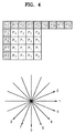
図4は、イントラ予測における予測様子を示す図である。図4を参照するに、16×16サイズのマクロブロックを4×4サイズに分割した後、このように分割されたブロック別に9個の予測方向を使用して予測画像が生成される。そうでなければ、16×16サイズのマクロブロックに対して、4個の予測方向を使用して予測画像が生成されることもある。前者の場合をさらに詳細に説明すれば、4×4サイズのブロックPa,Pb,…,Pqを予測するために、復元画像内の空間上隣接画素P0,P1,…,P12を利用する(41)。0から8までの9個の予測方向を使用して、隣接画素P0,P1,…,P12からPa,Pb,…,Pqを予測する(42)。0の方向を例と挙げれば、隣接画素P1,P2,P3,及びP4を0の方向に該当する垂直下降方向に投影することによって、Pa,Pe,Pi,及びPmはP1から予測し、Pb,Pf,Pj,及びPnはP2から予測し、Pc,Pg,Pk,及びPdはP3から予測し、Pd,Ph,Pl,及びPqはP4から予測する。他の方向の場合も同様に、前記のような投影によってPa,Pb,..,Pqが予測される。 FIG. 4 is a diagram illustrating a prediction state in intra prediction. Referring to FIG. 4, after a 16 × 16 size macroblock is divided into 4 × 4 sizes, a prediction image is generated using nine prediction directions for each of the divided blocks. Otherwise, a predicted image may be generated using four prediction directions for a 16 × 16 macroblock. The former case will be described in more detail. In order to predict 4 × 4 size blocks Pa, Pb,..., Pq, spatially adjacent pixels P0, P1,. ). 9 prediction directions from 0 to 8 are used to predict Pa, Pb,..., Pq from adjacent pixels P0, P1,. Taking the direction of 0 as an example, Pa, Pe, Pi, and Pm are predicted from P1 by projecting adjacent pixels P1, P2, P3, and P4 in the vertical downward direction corresponding to the direction of 0, and Pb , Pf, Pj, and Pn are predicted from P2, Pc, Pg, Pk, and Pd are predicted from P3, and Pd, Ph, Pl, and Pq are predicted from P4. Similarly, in other directions, Pa, Pb,..., Pq are predicted by the projection as described above.
YCoCg色空間を例と挙げれば、単一モードレジデュー生成部1211は、Y成分のマクロブロック、Co成分のマクロブロック、Cg成分のマクロブロックを何れも同じサイズに分割し、例えば、Y成分のマクロブロック、Co成分のマクロブロック、Cg成分のマクロブロックを何れも4×4サイズに分割し、このように分割されたY成分のブロック、Co成分のブロック、Cg成分のブロック別に同じ予測方向を決定する。また、RGB色空間を例と挙げれば、単一モードレジデュー生成部1211は、R成分のマクロブロック、G成分のマクロブロック、B成分のマクロブロックを何れも同じサイズに分割し、例えば、R成分のマクロブロック、G成分のマクロブロック、B成分のマクロブロックを何れも4×4サイズに分割し、このように分割されたR成分のブロック、G成分のブロック、B成分のブロック別に同じ予測方向を決定する。
Taking the YCoCg color space as an example, the single mode
前記のように、単一モードレジデュー生成部1211は、異なる色成分のそれぞれに同じ時間上予測方式及び同じ空間上予測方式を適用するために、色成分のそれぞれのレジデュー間の類似性が大きくなる。また、ブロックのサイズ、動きベクトル、予測方向が全ての色成分に一律的に適用されるため、色成分ごとにこのような情報を符号化させる必要なく、全ての色成分に対して、1回のみこのような情報を符号化させればよいため、全体的な符号化効率を高めうるという長所がある。
As described above, since the single mode
複合モードレジデュー生成部1212は、最適モード選択部110によって選択された予測モードが複合予測モードであれば、複合予測モードによって現在画像と参照画像との時間的重畳性を除去する時間上予測(以下、“複合インター予測”という)を行うか、または現在画像の色成分のそれぞれのマクロブロックに独立的に適用される予測モードによって、現在画像内の空間的重複性を除去する空間上予測(以下、“複合イントラ予測”という)を行うことによって予測画像を生成する。また、複合モードレジデュー生成部1212は、現在画像とこのように生成された予測画像との差に該当するレジデューを生成する。
If the prediction mode selected by the optimal
さらに詳細に説明すれば、複合モードレジデュー生成部1212は、現在画像の色成分のそれぞれのマクロブロックに独立的に適用されるサイズに色成分のそれぞれのマクロブロックを分割し、このように分割された色成分のそれぞれのブロック別に色成分のそれぞれのブロックに独立的に適用される参照画像と現在画像との間の動きベクトルを決定し、このように決定された動きベクトルを使用して、参照画像から現在画像に対する予測画像を生成することによって複合インター予測を行う。
More specifically, the composite mode
すなわち、複合モードレジデュー生成部1212は、現在画像の色成分のそれぞれのマクロブロックを異なるサイズに分割し、このように分割された色成分のそれぞれのブロック別に異なる動きベクトルを決定し、このように決定された動きベクトルを使用して参照画像から現在画像に対する予測画像を生成することによって、複合インター予測を行う。もちろん、複合モードレジデュー生成部1212は、現在画像の色成分のそれぞれのマクロブロックに独立的に適用される予測モードによってインター予測を行うため、現在画像の色成分のそれぞれのマクロブロックを同じサイズに分割し、このように分割された色成分のそれぞれのブロック別に同じ動きベクトルを決定することもある。
That is, the composite mode
YCoCg色空間を例と挙げれば、複合モードレジデュー生成部1212は、Y成分のマクロブロック、Co成分のマクロブロック、Cg成分のマクロブロックを異なるサイズに分割し、例えば、Y成分のマクロブロックを4×4、Co成分のマクロブロックを8×8、Cg成分のマクロブロックを8×8のサイズに分割し、このように分割されたY成分のブロック、Co成分のブロック、Cg成分のブロック別に異なる動きベクトルを決定する。また、RGB色空間を例と挙げれば、複合モードレジデュー生成部1212は、R成分のマクロブロック、G成分のマクロブロック、B成分のマクロブロックを異なるサイズに分割し、例えば、R成分のマクロブロックを8×8、G成分のマクロブロックを4×4、B成分のマクロブロックを8×8のサイズに分割し、このように分割されたR成分のブロック、G成分のブロック、B成分のブロック別に異なる動きベクトルを決定する。
Taking the YCoCg color space as an example, the composite mode
また、複合モードレジデュー生成部1212は、現在画像の色成分のそれぞれのマクロブロックに独立的に適用されるサイズに色成分のそれぞれのマクロブロックを分割し、このように分割された色成分のそれぞれのブロック別に色成分のそれぞれのブロックに独立的に適用される予測方向を決定し、このように決定された予測方向を使用して、復元画像生成部180によって生成された復元画像内の隣接画素から現在画像を構成するブロックを予測し、このように予測されたブロックで構成された予測画像を生成することによって、複合イントラ予測を行う。
Also, the composite mode
すなわち、複合モードレジデュー生成部1212は、現在画像の色成分のそれぞれのマクロブロックを異なるサイズに色成分のそれぞれのマクロブロックを分割し、このように分割された色成分のそれぞれのブロック別に異なる予測方向を決定し、このように決定された予測方向を使用して、復元画像生成部180によって生成された復元画像内の隣接画素から現在画像を構成するブロックを予測し、このように予測されたブロックで構成された予測画像を生成することによって、複合イントラ予測を行う。もちろん、複合モードレジデュー生成部1212は、現在画像の色成分のそれぞれのマクロブロックに独立的に適用される予測モードによってイントラ予測を行うため、現在画像の色成分のそれぞれのマクロブロックを同じサイズに分割し、このように分割された色成分のそれぞれのブロック別に同じ動きベクトルを決定することもある。
In other words, the composite mode
YCoCg色空間を例と挙げれば、複合モードレジデュー生成部1212は、Y成分のマクロブロック、Co成分のマクロブロック、Cg成分のマクロブロックを異なるサイズに分割し、例えば、Y成分のマクロブロックを4×4、Co成分のマクロブロックを16×16、Cg成分のマクロブロックを16×16のサイズに分割し、このように分割されたY成分のブロック、Co成分のブロック、Cg成分のブロック別に異なる予測方向を決定する。また、RGB色空間を例と挙げれば、複合モードレジデュー生成部1212は、R成分のマクロブロック、G成分のマクロブロック、B成分のマクロブロックを異なるサイズに分割し、例えば、R成分のマクロブロックを16×16、G成分のマクロブロックを4×4、B成分のマクロブロックを16×16のサイズに分割し、このように分割されたR成分のブロック、G成分のブロック、B成分のブロック別に異なる予測方向を決定する。
Taking the YCoCg color space as an example, the composite mode
さらに、複合モードレジデュー生成部1212は、現在画像の色成分のそれぞれのマクロブロック別に複合インター予測または複合イントラ予測を行うこともある。すなわち、複合モードレジデュー生成部1212は、現在画像の色成分のそれぞれのマクロブロックのうち何れか一つの色成分のマクロブロックに対しては、複合インター予測を行い、他の色成分のマクロブロックに対しては、複合イントラ予測を行うこともある。
Further, the composite mode
前記のように、複合モードレジデュー生成部1212は、異なる色成分の間に異なる時間上予測方式と異なる空間上予測方式とを行うため、色成分の間に類似性があまりなければ、相互間にそれぞれ独立的な符号化方法を使用して各色成分に最適の方法を使用することによって、予測符号化を効果的に行って、結局、全体的な符号化効率を高めうるが、色成分に独立的に適用されるブロックのサイズ、動きベクトル、及び予測方向を1回のみ符号化すればよいため、符号化効率を高めうる。
As described above, the composite mode
図5は、図1に示されたレジデュー生成部120の他の構成図である。図5を参照するに、図5に示されたレジデュー生成部120は、単一モードレジデュー生成部1221、レジデュー変換部1222、及び複合モードレジデュー生成部1223で構成される。単一モードレジデュー生成部1221及び複合モードレジデュー生成部1223は、図2に示された単一モードレジデュー生成部1211及び複合モードレジデュー生成部1212と同じ機能を行う。
FIG. 5 is another configuration diagram of the
しかしながら、単一モードレジデュー生成部1221でのインター予測またはイントラ予測以後にも、色成分間には重畳性が残っている。レジデュー変換部1222は、このような色成分間の重畳性を除去する役割を行う。単一モードレジデュー生成部1221によって生成されたレジデューとレジデュー変換部1222によって生成されたレジデューとを区別するために、前者を“第1レジデュー”と称し、後者を“第2レジデュー”と称す。
However, even after inter prediction or intra prediction in the single mode
レジデュー変換部1222は、最適モード選択部110によって選択された予測モードがレジデュー変換モードであれば、単一モードレジデュー生成部1221によって生成された第1レジデュー間の差に該当する第2レジデューを生成する。
If the prediction mode selected by the optimum
図6は、図1に示されたレジデュー生成部120のさらに他の構成図である。図6を参照するに、図6に示されたレジデュー生成部120は、単一モードレジデュー生成部1231、RCT(Residual Color Transformation)変換部1232、IPP(Inter−Plane Prediction)変換部1233、及びRCP(Residual Color Prediction)変換部1234、及び複合モードレジデュー生成部1235で構成される。単一モードレジデュー生成部1231及び複合モードレジデュー生成部1235は、図2に示された単一モードレジデュー生成部1211及び複合モードレジデュー生成部1212と同じ機能を行う。前記と同様に、単一モードレジデュー生成部1231によって生成されたレジデューWARCT変換部1232、IPP変換部1233、及びRCP変換部1234によって生成されたレジデューを区別するために、前者を“第1レジデュー”と称し、後者を“第2レジデュー”と称す。
FIG. 6 is still another configuration diagram of the
単一モードレジデュー生成部1221によって生成された第1レジデュー間の差に該当する第2レジデューを生成する方式としては、RCT変換方式、IPP変換方式、RCP変換方式がある。RCT変換は、YCoCg色空間で第2レジデューを生成することによって、IPP変換は、RGB色空間で第2レジデューを生成することによって、RCP変換は、IPP変換と類似しているが、G成分のレジデューを予測子として使用する時に所定のフィルタリングを通じてノイズを除去した後にIPP変換と同じ変換を適用する。
As a method for generating the second residue corresponding to the difference between the first residences generated by the single mode
RCT変換部1232は、最適モード選択部110によって選択された予測モードがRCT変換モードであれば、YCoCg色空間で次の式(3)を利用してY成分、Co成分、Cg成分それぞれの第1レジデュー間の差に該当する第2レジデューを生成する。特に、Y=(R+2G+B)>>2、Co=(R−B)>>1、Cg=(−R+2G−B)>>2の関係にある。
If the prediction mode selected by the optimum
IPP変換部1233は、最適モード選択部110によって選択された予測モードがIPP変換モードであれば、このIPP変換モードによって、RGB色空間で次の式(4)を利用して、R成分、G成分、B成分のそれぞれの第1レジデュー間の差に該当する第2レジデューを生成する。
If the prediction mode selected by the optimum
RCP変換部1234は、最適モード選択部110によって選択された予測モードがRCP変換モードであれば、RCP変換モードによって、RGB色空間で次の式(5)のような5タップフィルタを使用して、R成分、G成分、B成分のそれぞれのノイズを除去した後、R成分、G成分、B成分のそれぞれの第1レジデュー間の差に該当する第2レジデューを生成する。
If the prediction mode selected by the optimum
図8は、図1に示されたレジデュー生成部120のさらに他の構成図である。図8を参照するに、図6に示されたレジデュー生成部120は、複合モードレジデュー生成部1241及びレジデュー変換部1242で構成される。複合モードレジデュー生成部1241は、図2に示された複合モードレジデュー生成部1212と同じ機能を行う。
FIG. 8 is still another configuration diagram of the
ところが、複合モードレジデュー生成部1241でのインター予測またはイントラ予測以後にも、色成分間には重畳性が残っている。レジデュー変換部1242は、このような色成分間の重畳性を除去する役割を行う。単一モードレジデュー生成部1241によって生成されたレジデューとレジデュー変換部1242によって生成されたレジデューとを区別するために、前者を“第1レジデュー”と称し、後者を“第2レジデュー”と称す。
However, even after inter prediction or intra prediction in the composite mode
レジデュー変換部1242は、最適モード選択部110によって選択された予測モードがレジデュー変換モードであれば、レジデュー変換モードによって、複合モードレジデュー生成部1241によって生成された第1レジデュー間の差に該当する第2レジデューを生成する。但し、複合モードレジデュー生成部1241でのインター予測またはイントラ予測以後にも、色成分間には重畳性が残っているが、単一モード方式に比べて、色成分間の類似性が低いため、レジデュー変換部1242での圧縮効率は、レジデュー変換部1222での圧縮効率よりは劣る。
If the prediction mode selected by the optimum
図9は、図2に示された復元画像生成部180の構成図である。図9を参照するに、図2に示された復元画像生成部180は、レジデュー逆変換部181及び予測補償部182で構成される。
FIG. 9 is a configuration diagram of the restored
レジデュー逆変換部181は、周波数空間逆変換部170によって復元された第2レジデュー間の合算に該当する第1レジデューを生成する。例えば、レジデュー逆変換部181は、次の式(8)を利用して、Y成分、Co成分、Cg成分のそれぞれの第2レジデュー間の合算に該当するY成分、Co成分、Cg成分のそれぞれの第1レジデューを生成する。
The residue
そうでなければ、レジデュー逆変換部181は、次の式(9)を利用して、R成分、G成分、B成分のそれぞれの第2レジデュー間の合算に該当するR成分、G成分、B成分のそれぞれの第1レジデューを生成する。
Otherwise, the residue
予測補償部182は、レジデュー生成部120によって生成された予測画像とレジデュー逆変換部181によって生成された第1レジデューとの合算に該当する復元画像を生成する。例えば、予測補償部182は、Y成分、Co成分、及びCg成分ごとに、レジデュー生成部120によって生成された予測画像とレジデュー逆変換部181によって生成された第1レジデューとの合算を算出することによって、YCoCg色空間での復元画像を生成する。そうでなければ、予測補償部182は、R成分、G成分、及びB成分ごとに、レジデュー生成部120によって生成された予測画像とレジデュー逆変換部181によって生成された第1レジデューとの合算を算出することによって、RGB色空間での復元画像を生成する。
The
図10は、本発明の望ましい一実施形態による動画復号化装置の構成図である。図10を参照するに、本実施形態による動画復号化装置は、エントロピー復号化部210、逆量子化部220、周波数空間逆変換部230、予測画面生成部240及び復元画像生成部250で構成される。
FIG. 10 is a block diagram of a moving picture decoding apparatus according to an embodiment of the present invention. Referring to FIG. 10, the moving picture decoding apparatus according to the present embodiment includes an
エントロピー復号化部210は、図1に示された動画符号化装置から出力されたビットストリームをエントロピー復号化することによって、現在画像に該当する整数値及び現在画像の色成分のそれぞれのブロックに最適の予測モードを表す情報を復元する。ここで、現在画像の色成分のそれぞれのブロックに最適である予測モードは、動画符号化装置で使われた予測モードである。
The
逆量子化部220は、エントロピー復号化部210によって復元された整数値を逆量子化することによって周波数成分値を復元する。すなわち、逆量子化部220は、エントロピー復号化部210によって復元された整数値に量子化パラメータを積算することによって周波数成分値を復元する。
The
周波数空間逆変換部230は、逆量子化部220によって復元された周波数成分値を周波数空間から色空間に変換することによって、現在画像と予測画像との差に該当するレジデューを生成する。そうでなければ、周波数空間逆変換部230は、逆量子化部220によって復元された周波数成分値を周波数空間から色空間に変換することによって、色成分のそれぞれの第1レジデュー間の差に該当する第2レジデューを復元する。
The frequency space
予測画像生成部240は、色成分のそれぞれのマクロブロック別にエントロピー復号化部210によって復元された情報が表す予測モードによって、現在画像に対する予測画像を生成する。
The predicted
復元画像生成部250は、予測画像生成部240によって生成された予測画像と周波数空間逆変換部230によって復元されたレジデューとの合算に該当する復元画像を生成する。そうでなければ、復元画像生成部250は、周波数空間逆変換部230によって復元された第2レジデュー間の合算に該当する第1レジデューを生成し、予測画像生成部240によって生成された予測画像とこのように生成された第1レジデュー間の合算に該当する復元画像とを生成する。
The restored
図11は、図10に示された予測画像生成部240の構成図である。図11を参照するに、図10に示された予測画像生成部240は、単一モード予測画像生成部241及び複合モード予測画像生成部242で構成される。
FIG. 11 is a configuration diagram of the predicted
単一モード予測画像生成部241は、エントロピー復号化部210によって復元された情報が単一予測モードを表せば、単一イントラ予測または単一インター予測を行うことによって予測画像を生成する。さらに詳細に説明すれば、単一モード予測画像生成部241は、現在画像の色成分のそれぞれのマクロブロックに一律的に適用されるサイズに分割されたブロック別に、色成分のそれぞれのブロックに一律的に適用される参照画像と現在画像との間の動きベクトルを使用して、参照画像から現在画像に対する予測画像を生成する。すなわち、単一モード予測画像生成部241は、現在画像の色成分のそれぞれのマクロブロックに対して同じサイズに分割されたブロック別に同じ動きベクトルを使用して、参照画像から現在画像に対する予測画像を生成する。
If the information restored by the
また、単一モード予測画像生成部241は、現在画像の色成分のそれぞれのマクロブロックに一律的に適用されるサイズに分割されたブロック別に、色成分のそれぞれのブロックに一律的に適用される予測方向を使用して、復元画像生成部250によって生成された復元画像内の隣接画素から現在画像を構成するブロックを予測し、このように予測されたブロックで構成された予測画像を生成する。すなわち、単一モードレジデュー生成部は、現在画像の色成分のそれぞれのマクロブロックに対して同じサイズに分割されたブロック別に同じ予測方向を使用して、復元画像生成部250によって生成された復元画像内の隣接画素から現在画像を構成するブロックを予測し、このように予測されたブロックで構成された予測画像を生成する。
Also, the single mode predicted
複合モード予測画像生成部242は、エントロピー復号化部210によって復元された情報が複合予測モードを表せば、複合インター予測または複合イントラ予測を行うことによって予測画像を生成する。さらに詳細に説明すれば、複合モード予測画像生成部242は、現在画像の色成分のそれぞれのマクロブロックに独立的に適用されるサイズに分割されたブロック別に、色成分のそれぞれのブロックに独立的に適用される参照画像と現在画像との間の動きベクトルを使用して、参照画像から現在画像に対する予測画像を生成する。すなわち、複合モード予測画像生成部242は、現在画像の色成分のそれぞれのマクロブロックに対して、異なるサイズに分割された色成分のそれぞれのブロック別に異なる動きベクトルを使用して、参照画像から現在画像に対する予測画像を生成する。
If the information restored by the
また、複合モード予測画像生成部242は、現在画像の色成分のそれぞれのマクロブロックに独立的に適用されるサイズに分割されたブロック別に、色成分のそれぞれのブロックに一律的に適用される予測方向を使用して、復元画像生成部250によって生成された復元画像内の隣接画素から現在画像を構成するブロックを予測し、このように予測されたブロックで構成された予測画像を生成することによって、複合イントラ予測を行う。すなわち、複合モード予測画像生成部242は、現在画像の色成分のそれぞれのマクロブロックに対して、異なるサイズに分割されたブロック別に異なる予測方向を使用して、復元画像生成部250によって生成された復元画像内の隣接画素から現在画像を構成するブロックを予測し、このように予測されたブロックで構成された予測画像を生成する。
In addition, the composite mode predicted
図12は、図10に示された復元画像生成部250の構成図である。図12を参照するに、図10に示された復元画像生成部250は、レジデュー逆変換部251及び予測補償部252で構成される。
FIG. 12 is a configuration diagram of the restored
レジデュー逆変換部251は、エントロピー復号化部210によって復元された情報がレジデュー変換モードを表せば、周波数空間逆変換部230によって復元された第2レジデュー間の合算に該当する第1レジデューを生成する。例えば、レジデュー逆変換部251は、前記の式(8)を利用して、Y成分、Co成分、Cg成分のそれぞれの第2レジデュー間の合算に該当するY成分、Co成分、Cg成分のそれぞれの第1レジデューを生成する。そうでなければ、レジデュー逆変換部251は、前記の式(9)を利用して、R成分、G成分、B成分のそれぞれの第2レジデュー間の合算に該当するR成分、G成分、B成分のそれぞれの第1レジデューを生成する。
If the information restored by the
予測補償部252は、予測画像生成部240によって生成された予測画像とレジデュー逆変換部251によって生成された第1レジデューとの合算に該当する復元画像を生成する。例えば、予測補償部252は、Y成分、Co成分、及びCg成分ごとに予測画像生成部240によって生成された予測画像とレジデュー逆変換部251によって生成された第1レジデューとの合算を算出することによって、YCoCg色空間での復元画像を生成する。そうでなければ、予測補償部252は、R成分、G成分、及びB成分ごとに予測画像生成部240によって生成された予測画像とレジデュー逆変換部251によって生成された第1レジデューとの合算を算出することによって、RGB色空間での復元画像を生成する。
The
図13は、図12に示されたレジデュー逆変換部251の構成図である。図13を参照するに、図12に示されたレジデュー逆変換部251は、RCT変換部2511、IPP変換部2512、及びRCP変換部2513で構成される。
FIG. 13 is a configuration diagram of the residue
RCT変換部2511は、エントロピー復号化部210によって復元された情報がRCT変換モードを表せば、前記の式(8)を利用して、Y成分、Co成分、Cg成分のそれぞれの第2レジデュー間の合算に該当するY成分、Co成分、Cg成分のそれぞれの第1レジデューを生成する。
If the information reconstructed by the
IPP変換部2512は、エントロピー復号化部210によって復元された情報がIPP変換モードを表せば、前記の式(9)を利用して、R成分、G成分、B成分のそれぞれの第2レジデュー間の合算に該当するR成分、G成分、B成分のそれぞれの第1レジデューを生成する。
If the information restored by the
RCP変換部2513は、エントロピー復号化部210によって復元された情報がRCP変換モードを表せば、前記の式(9)を利用して、R成分、G成分、B成分のそれぞれの第2レジデュー間の合算に該当するR成分、G成分、B成分のそれぞれの第1レジデューを生成する。
If the information restored by the
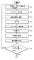
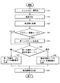
図14A及び図14Bは、本発明の望ましい一実施形態による動画符号化方法を示すフローチャートである。図14A及び図14Bを参照するに、本実施形態による動画符号化方法は、図1に示された動画符号化装置で時系列的に処理されるステップで構成される。したがって、以下省略された内容であっても、図1に示された動画符号化装置について前述された内容は、本実施形態による動画符号化方法にも適用される。 14A and 14B are flowcharts illustrating a moving image encoding method according to an exemplary embodiment of the present invention. Referring to FIGS. 14A and 14B, the moving picture coding method according to the present embodiment includes steps processed in time series by the moving picture coding apparatus shown in FIG. Therefore, even if the content is omitted below, the content described above for the video encoding device shown in FIG. 1 is also applied to the video encoding method according to the present embodiment.
ステップ1401で、動画符号化装置は、サンプル画像に対して全ての可能な予測モードのうち何れか一つを選択する。特に、下記のステップ1406からステップ1401に戻った場合には、動画符号化装置は、全ての可能な予測モードのうち、既に選択された予測モードを除外したもののうち何れか一つを選択する。
In
ステップ1402で、動画符号化装置は、ステップ1401で選択された予測モードによって、色成分のそれぞれのマクロブロック別に現在画像に対する予測画像を生成し、現在画像と予測画像との差に該当するレジデューを生成する。そうでなければ、ステップ1402で、動画符号化装置は、ステップ1401で選択された予測モードによって色成分のそれぞれのマクロブロック別に現在画像に対する予測画像を生成し、現在画像と予測画像との差に該当する第1レジデューを生成し、色成分のそれぞれの第1レジデュー間の差に該当する第2レジデューを生成する。
In
ステップ1403で、動画符号化装置は、ステップ1402で生成されたレジデューを色空間から周波数空間に変換する。そうでなければ、ステップ1403で、動画符号化装置は、ステップ1402で生成された第2レジデューを色空間から周波数空間に変換する。
In
ステップ1404で、動画符号化装置は、ステップ1403で変換された値を量子化する。
In
ステップ1405で、動画符号化装置は、ステップ1404で量子化された値及びステップ1401で選択された予測モードを表す情報をエントロピー符号化することによって、ビットストリームを生成する。
In
ステップ1406で、動画符号化装置は、ステップ1404で量子化された値を逆量子化することによって周波数成分値を復元する。
In
ステップ1407で、動画符号化装置は、ステップ1406で復元された周波数成分値を周波数空間から色空間に変換することによって、現在画像と予測画像との差に該当するレジデューを復元する。そうでなければ、ステップ1407で動画符号化装置は、ステップ1406で復元された周波数成分値を周波数空間から色空間に変換することによって、色成分のそれぞれの第1レジデュー間の差に該当する第2レジデューを復元する。
In
ステップ1408で、動画符号化装置は、ステップ1402で生成された予測画像とステップ1407によって復元されたレジデュー間の合算に該当する復元画像とを生成する。そうでなければ、ステップ1408で、動画符号化装置は、ステップ1407で復元された第2レジデュー間の合算に該当する第1レジデューを生成し、ステップ1402で生成された予測画像とこのように生成された第1レジデュー間の合算に該当する復元画像とを生成する。
In
ステップ1409で、動画符号化装置は、全ての予測モードに対して、前記ステップ1401〜1408が行われたか否かを判断し、もし、全ての予測モードに対して前記ステップ1401〜1408が行われた場合には、ステップ1410に進み、行われていない場合には、ステップ1401に戻る。
In
ステップ1410で、動画符号化装置は、サンプル画像の特性、すなわち、ステップ1401〜1409で行われた結果に基づいて、現在画像の色成分のそれぞれのマクロブロック別に色成分のそれぞれのマクロブロックに最適の予測モードを選択する。すなわち、ステップ1410で、動画符号化装置は、現在画像の色成分のそれぞれのマクロブロックに最適の予測モードとして、ステップ1405で生成されたビットストリームの量及びサンプル画像とステップ1408で生成された復元画像との間の画質の歪曲が最も少ない予測モードを選択する。
In
ステップ1411で、動画符号化装置は、ステップ1410で選択された予測モードによって、色成分のそれぞれのマクロブロック別に現在画像に対する予測画像を生成し、現在画像と予測画像との差に該当するレジデューを生成する。そうでなければ、ステップ1411で、動画符号化装置は、ステップ1410で選択された予測モードによって色成分のそれぞれのマクロブロック別に現在画像に対する予測画像を生成し、現在画像と予測画像との差に該当する第1レジデューを生成し、色成分のそれぞれの第1レジデュー間の差に該当する第2レジデューを生成する。
In
ステップ1412で、動画符号化装置は、ステップ1411で生成されたレジデューを色空間から周波数空間に変換する。そうでなければ、ステップ1412で、動画符号化装置は、ステップ1411で生成された第2レジデューを色空間から周波数空間に変換する。
In
ステップ1413で、動画符号化装置は、ステップ1414で変換された値を量子化する。
In
ステップ1414で、動画符号化装置は、ステップ1413で量子化された値及びステップ1410で選択された予測モードを表す情報をエントロピー符号化することによって、ビットストリームを生成する。
In
ステップ1415で、動画符号化装置は、ステップ1413で量子化された値を逆量子化することによって周波数成分値を復元する。
In
ステップ1416で、動画符号化装置は、ステップ1415で復元された周波数成分値を周波数空間から色空間に変換することによって、現在画像と予測画像との差に該当するレジデューを復元する。そうでなければ、ステップ1416で、動画符号化装置は、ステップ1415で復元された周波数成分値を周波数空間から色空間に変換することによって、色成分のそれぞれの第1レジデュー間の差に該当する第2レジデューを復元する。
In
ステップ1417で、動画符号化装置は、ステップ1411で生成された予測画像とステップ1416で復元されたレジデュー間の合算に該当する復元画像とを生成する。そうでなければ、ステップ1417で、動画符号化装置は、ステップ1416で復元された第2レジデュー間の合算に該当する第1レジデューを生成し、ステップ1411で生成された予測画像とこのように生成された第1レジデュー間の合算に該当する復元画像とを生成する。
In
図15は、本発明の望ましい一実施形態による動画復号化方法を示すフローチャートである。図15を参照するに、本実施形態による動画復号化方法は、図10に示された動画復号化装置で時系列的に処理されるステップで構成される。したがって、以下省略された内容であっても、図10に示された動画復号化装置について前述された内容は、本実施形態による動画復号化方法にも適用される。 FIG. 15 is a flowchart illustrating a moving picture decoding method according to an exemplary embodiment of the present invention. Referring to FIG. 15, the moving picture decoding method according to the present embodiment includes steps processed in time series by the moving picture decoding apparatus shown in FIG. Therefore, the contents described above for the moving picture decoding apparatus shown in FIG. 10 are also applied to the moving picture decoding method according to the present embodiment even if the contents are omitted below.
ステップ1501で、動画復号化装置は、図1に示された動画符号化装置から出力されたビットストリームをエントロピー復号化することによって、現在画像に該当する整数値及び現在画像の色成分のそれぞれのブロックに最適の予測モードを表す情報を復元する。
In
ステップ1502で、動画復号化装置は、ステップ1501で復元された整数値を逆量子化することによって周波数成分値を復元する。
In
ステップ1503で、動画復号化装置は、ステップ1502で復元された周波数成分値を周波数空間から色空間に変換することによって、現在画像と予測画像との差に該当するレジデューを生成する。そうでなければ、ステップ1503で、動画復号化装置は、ステップ1502で復元された周波数成分値を周波数空間から色空間に変換することによって、色成分のそれぞれの第1レジデュー間の差に該当する第2レジデューを復元する。
In
ステップ1504で、動画復号化装置は、ステップ1501で復元された情報がレジデュー変換モードを表せば、ステップ1505に進み、表さなければ、ステップ1506に進む。
In
ステップ1505で、動画復号化装置は、ステップ1502で復元された第2レジデュー間の合算に該当する第1レジデューを生成する。特に、ステップ1505で、動画復号化装置は、ステップ1501で復元された情報がRCT変換モードを表せば、前記の式(8)を利用して、Y成分、Co成分、Cg成分のそれぞれの第2レジデュー間の合算に該当するY成分、Co成分、Cg成分のそれぞれの第1レジデューを生成する。また、ステップ1505で、動画復号化装置は、ステップ1501で復元された情報がIPP変換モードまたはRCP変換モードを表せば、前記の式(9)を利用して、R成分、G成分、B成分のそれぞれの第2レジデュー間の合算に該当するR成分、G成分、B成分のそれぞれの第1レジデューを生成する。
In
RCP変換部1234は、エントロピー復号化部210によって復元された情報がRCP変換モードを表せば、前記の式(9)を利用して、R成分、G成分、B成分のそれぞれの第2レジデュー間の合算に該当するR成分、G成分、B成分のそれぞれの第1レジデューを生成する。
If the information restored by the
ステップ1506で、動画復号化装置は、ステップ1501で復元された情報が単一予測モードを表せば、ステップ1507に進み、複合予測モードを表せば、ステップ1508に進む。
In
ステップ1507で、動画復号化装置は、現在画像の色成分のそれぞれのブロックに一律的に適用されるサイズに分割されたブロック別に、色成分のそれぞれのブロックに一律的に適用される動きベクトルを使用して予測画面を生成するか、または色成分のそれぞれのブロックに一律的に適用される予測方向を使用して予測画面を生成する。
In
ステップ1508で、動画復号化装置は、現在画像の色成分のそれぞれのブロックに独立的に適用されるサイズに分割されたブロック別に、色成分のそれぞれのブロックに独立的に適用される動きベクトルを使用して予測画面を生成するか、または色成分のそれぞれのブロックに独立的に適用される予測方向を使用して予測画面を生成する。
In
ステップ1509で、動画復号化装置は、ステップ1507またはステップ1508で生成された予測画像とステップ1503で復元されたレジデュー間の合算に該当する復元画像とを生成する。そうでなければ、復元画像生成部250は、ステップ1507またはステップ1508で生成された予測画像とステップ1505で生成された第1レジデュー間の合算に該当する復元画像とを生成する。
In
一方、前述した本発明の実施形態は、コンピュータで実行できるプログラムで作成可能であり、コンピュータで読み取り可能な記録媒体を利用して、前記プログラムを動作させる汎用デジタルコンピュータで具現される。また、前述した本発明の実施形態で使われたデータの構造は、コンピュータで読み取り可能な記録媒体に多様な手段を通じて記録される。 On the other hand, the above-described embodiment of the present invention can be created by a program that can be executed by a computer, and is embodied by a general-purpose digital computer that operates the program using a computer-readable recording medium. The data structure used in the above-described embodiment of the present invention is recorded on a computer-readable recording medium through various means.
前記コンピュータで読み取り可能な記録媒体は、マグネチック保存媒体(例えば、ROM(Read Only Memory)、フロッピー(登録商標)ディスク、ハードディスクなど)、光学的判読媒体(例えば、CD−ROM、DVDなど)及びキャリアウェーブ(例えば、インターネットを通じた伝送)のような保存媒体を含む。 The computer-readable recording medium includes a magnetic storage medium (for example, a ROM (Read Only Memory), a floppy (registered trademark) disk, a hard disk, etc.), an optical interpretation medium (for example, a CD-ROM, a DVD, etc.) and Includes storage media such as carrier waves (eg, transmission over the Internet).
以上、本発明についてその望ましい実施形態を中心に説明した。当業者は、本発明が本発明の本質的な特性から逸脱しない範囲で変形された形態で具現されるということが分かるであろう。したがって、開示された実施形態は、限定的な観点でなく、説明的な観点で考慮されねばならない。本発明の範囲は、前述した説明でなく、特許請求の範囲に現れており、それと同等な範囲内にある全ての差異点は、本発明に含まれていると解釈されねばならない。 In the above, this invention was demonstrated centering on the desirable embodiment. Those skilled in the art will appreciate that the present invention may be embodied in variations that do not depart from the essential characteristics of the invention. Accordingly, the disclosed embodiments should be considered in an illustrative, not a limiting sense. The scope of the present invention is shown not in the above description but in the claims, and all differences within the equivalent scope should be construed as being included in the present invention.
Claims (39)
(b)前記選択された予測モードによって、前記現在画像に対する予測画像を生成するステップと、を含む予測画像の生成方法。 (A) selecting an optimal prediction mode for each block of the color component for each block of the color component of the current image based on the characteristics of the predetermined image;
And (b) generating a predicted image for the current image according to the selected prediction mode.
前記色成分のそれぞれのマクロブロックに一律的に適用されるサイズに前記色成分のそれぞれのマクロブロックを分割するステップと、
前記分割された色成分のそれぞれのブロック別に、前記色成分のそれぞれのブロックに一律的に適用される参照画像と現在画像との間の動きベクトルを決定するステップと、
前記決定された動きベクトルを使用して参照画像から現在画像に対する予測画像を生成するステップと、を含むことを特徴とする請求項1に記載の予測画像の生成方法。 The step (b)
Dividing each macroblock of the color component into a size that is uniformly applied to each macroblock of the color component;
Determining a motion vector between a reference image and a current image uniformly applied to each block of the color component for each block of the divided color component;
The method according to claim 1, further comprising: generating a predicted image for a current image from a reference image using the determined motion vector.
前記色成分のそれぞれのマクロブロックに一律的に適用されるサイズに色成分のそれぞれのマクロブロックを分割するステップと、
前記分割された色成分のそれぞれのブロック別に色成分のそれぞれのブロックに一律的に適用される予測方向を決定するステップと、
前記決定された予測方向を使用して復元画像内の隣接画素から現在画像を構成するブロックを予測し、前記予測されたブロックで構成された予測画像を生成するステップと、を含むことを特徴とする請求項1に記載の予測画像の生成方法。 The step (b)
Dividing each macroblock of color components into a size that is uniformly applied to each macroblock of the color components;
Determining a prediction direction uniformly applied to each block of color components for each block of the divided color components;
Predicting a block constituting a current image from neighboring pixels in a restored image using the determined prediction direction, and generating a predicted image composed of the predicted block. The prediction image generating method according to claim 1.
前記色成分のそれぞれのマクロブロックに独立的に適用されるサイズに前記色成分のそれぞれのマクロブロックを分割するステップと、
前記分割された色成分のそれぞれのブロック別に前記色成分のそれぞれのブロックに独立的に適用される参照画像と現在画像との間の動きベクトルを決定するステップと、
前記決定された動きベクトルを使用して参照画像から現在画像に対する予測画像を生成するステップと、を含むことを特徴とする請求項1に記載の予測画像の生成方法。 The step (b)
Dividing each macroblock of the color component into a size that is independently applied to each macroblock of the color component;
Determining a motion vector between a reference image and a current image independently applied to each block of the color component for each block of the divided color component;
The method according to claim 1, further comprising: generating a predicted image for a current image from a reference image using the determined motion vector.
前記色成分のそれぞれのマクロブロックに独立的に適用されるサイズに色成分のそれぞれのマクロブロックを分割するステップと、
前記分割された色成分のそれぞれのブロック別に色成分のそれぞれのブロックに独立的に適用される予測方向を決定するステップと、
前記決定された予測方向を使用して復元画像内の隣接画素から現在画像を構成するブロックを予測し、前記予測されたブロックで構成された予測画像を生成するステップと、を含むことを特徴とする請求項1に記載の予測画像の生成方法。 The step (b)
Dividing each macroblock of color components into sizes that are independently applied to each macroblock of the color components;
Determining a prediction direction to be independently applied to each block of color components for each block of the divided color components;
Predicting a block constituting a current image from neighboring pixels in a restored image using the determined prediction direction, and generating a predicted image composed of the predicted block. The prediction image generating method according to claim 1.
前記選択された予測モードによって、前記現在画像に対する予測画像を生成するステップと、を含む予測画像の生成方法をコンピュータで実行させるためのプログラムを記録したコンピュータで読み取り可能な記録媒体。 Selecting an optimal prediction mode for each block of the color component for each block of the color component of the current image based on the characteristics of the predetermined image;
Generating a predicted image for the current image according to the selected prediction mode; and a computer-readable recording medium storing a program for causing the computer to execute a predicted image generation method.
前記選択された予測モードによって、前記現在画像に対する予測画像を生成する生成部と、を備える予測画像生成装置。 A selection unit that selects an optimal prediction mode for each block of the color component for each block of the color component of the current image based on characteristics of the predetermined image;
A prediction image generation apparatus comprising: a generation unit configured to generate a prediction image for the current image according to the selected prediction mode.
(b)前記選択された予測モードによって、前記現在画像に対する予測画像を生成するステップと、
(c)前記現在画像と前記予測画像との差に該当する色成分のそれぞれのレジデューを生成するステップと、
(d)前記生成されたレジデューを符号化することによってビットストリームを生成するステップと、を含むことを特徴とする符号化方法。 (A) selecting an optimal prediction mode for each block of the color component for each block of the color component of the current image based on the characteristics of the predetermined image;
(B) generating a predicted image for the current image according to the selected prediction mode;
(C) generating each residue of color components corresponding to the difference between the current image and the predicted image;
And (d) generating a bitstream by encoding the generated residue.
(e)前記選択された予測モードによって、前記色成分のそれぞれの第1レジデュー間の差に該当する第2レジデューを生成するステップをさらに含み、
前記(d)ステップは、前記生成された第1レジデューまたは前記生成された第2レジデューを符号化することによって、前記ビットストリームを生成することを特徴とする請求項12に記載の符号化方法。 The residence is a first residence,
(E) generating a second residue corresponding to a difference between each first residue of the color components according to the selected prediction mode;
The encoding method according to claim 12, wherein the step (d) generates the bitstream by encoding the generated first residue or the generated second residue.
前記選択された予測モードによって、前記現在画像に対する予測画像を生成し、前記現在画像と前記予測画像との差に該当する色成分のそれぞれのレジデューを生成する生成部と、
前記生成されたレジデューを符号化することによってビットストリームを生成する符号化部と、を備えることを特徴とする符号化装置。 A selection unit that selects an optimal prediction mode for each block of the color component for each block of the color component of the current image based on characteristics of the predetermined image;
A generation unit that generates a prediction image for the current image according to the selected prediction mode, and generates each residue of color components corresponding to a difference between the current image and the prediction image;
An encoding device comprising: an encoding unit that generates a bitstream by encoding the generated residue.
(b)前記復元された情報が表す予測モードによって、前記現在画像に対する予測画像を生成するステップと、を含むことを特徴とする予測画像の生成方法。 (A) restoring information representing a prediction mode optimal for each block of color components of the current image by decoding the bitstream;
And (b) generating a predicted image for the current image according to a prediction mode represented by the restored information.
前記復元された情報が表す予測モードによって前記現在画像に対する予測画像を生成するステップと、を含むことを特徴とする予測画像の生成方法をコンピュータで実行させるためのプログラムを記録したコンピュータで読み取り可能な記録媒体。 Restoring the information representing the optimal prediction mode for each block of the color components of the current image by decoding the bitstream;
Generating a predicted image for the current image in accordance with a prediction mode represented by the restored information, and capable of being read by a computer recording a program for causing the computer to execute a predicted image generation method recoding media.
前記復元された情報が表す予測モードによって、前記現在画像に対する予測画像を生成する生成部と、を備えることを特徴とする予測画像生成装置。 A decoding unit that restores information representing a prediction mode optimal for each block of color components of the current image by decoding the bitstream;
A predicted image generation apparatus comprising: a generation unit configured to generate a predicted image for the current image according to a prediction mode represented by the restored information.
(b)前記復元された情報が表す予測モードによって、前記現在画像と前記現在画像に対する予測画像との差に該当するレジデューを生成するステップと、
(c)前記復元された情報が表す予測モードによって、前記予測画像を生成するステップと、
(d)前記生成されたレジデューと前記生成された予測画面との合算に該当する復元画面を生成するステップと、を含むことを特徴とする復号化方法。 (A) restoring information representing a prediction mode optimal for each block of color components of the current image by decoding the bitstream;
(B) generating a residue corresponding to a difference between the current image and a predicted image with respect to the current image according to a prediction mode represented by the restored information;
(C) generating the predicted image according to a prediction mode represented by the restored information;
(D) generating a restoration screen corresponding to the sum of the generated residue and the generated prediction screen; and a decoding method comprising:
(e)前記色成分のそれぞれの第1レジデュー間の差に該当する第2レジデューを復元するステップをさらに含み、
前記(b)ステップは、前記復元された情報が表す予測モードによって、前記復元された第2レジデュー間の合算に該当する第1レジデューを生成することを特徴とする請求項33に記載の復号化方法。 The residence is a first residence,
(E) further comprising restoring a second residue corresponding to a difference between each first residue of the color components;
The decoding according to claim 33, wherein the step (b) generates a first residence corresponding to a sum of the restored second residences according to a prediction mode represented by the restored information. Method.
前記復元された整数値を逆量子化することによって周波数成分値を復元するステップと、をさらに含み、
前記(e)ステップは、前記復元された周波数成分値を周波数空間から色空間に変換することによって、前記色成分のそれぞれの第1レジデュー間の差に該当する第2レジデューを復元することを特徴とする請求項34に記載の復号化方法。 The step (a) restores the integer value and the information corresponding to the current image by entropy decoding the bitstream,
Reconstructing frequency component values by dequantizing the reconstructed integer values, and
The step (e) restores a second residue corresponding to a difference between the respective first residences of the color component by converting the restored frequency component value from a frequency space to a color space. The decoding method according to claim 34.
前記復元された情報が表す予測モードによって、前記現在画像と前記現在画像に対する予測画像との差に該当するレジデューを生成するステップと、
前記復元された情報が表す予測モードによって前記予測画像を生成するステップと、
前記生成されたレジデューと前記生成された予測画面との合算に該当する復元画面を生成するステップと、を含むことを特徴とする復号化方法をコンピュータで実行させるためのプログラムを記録したコンピュータで読み取り可能な記録媒体。 Restoring the information representing the optimal prediction mode for each block of the color components of the current image by decoding the bitstream;
Generating a residue corresponding to a difference between the current image and a predicted image with respect to the current image according to a prediction mode represented by the restored information;
Generating the predicted image according to a prediction mode represented by the restored information;
Generating a restoration screen corresponding to the sum of the generated residue and the generated prediction screen, and reading the program on a computer recording a program for causing the computer to execute the decoding method Possible recording media.
前記復元された情報が表す予測モードによって前記予測画像を生成する第1生成部と、
前記復元された情報が表す予測モードによって、前記現在画像と前記現在画像に対する予測画像との差に該当するレジデューを生成し、前記生成されたレジデューと前記生成された予測画面との合算に該当する復元画面を生成する第2生成部と、を備えることを特徴とする復号化装置。 A decoding unit that restores information representing a prediction mode optimal for each block of color components of the current image by decoding the bitstream;
A first generation unit that generates the prediction image according to a prediction mode represented by the restored information;
According to the prediction mode represented by the restored information, a residue corresponding to a difference between the current image and a predicted image with respect to the current image is generated, and corresponds to a sum of the generated residue and the generated prediction screen. And a second generation unit for generating a restoration screen.
Applications Claiming Priority (3)
| Application Number | Priority Date | Filing Date | Title |
|---|---|---|---|
| US78137906P | 2006-03-13 | 2006-03-13 | |
| KR1020060049080A KR101330630B1 (en) | 2006-03-13 | 2006-05-30 | Method and apparatus for encoding moving picture, method and apparatus for decoding moving picture, applying adaptively an optimal prediction mode |
| PCT/KR2007/001217 WO2007105900A1 (en) | 2006-03-13 | 2007-03-13 | Method, medium, and system encoding and/or decoding moving pictures by adaptively applying optimal prediction modes |
Related Child Applications (1)
| Application Number | Title | Priority Date | Filing Date |
|---|---|---|---|
| JP2011225278A Division JP2012034410A (en) | 2006-03-13 | 2011-10-12 | Method and apparatus for generating prediction video, and recording medium |
Publications (1)
| Publication Number | Publication Date |
|---|---|
| JP2009529845A true JP2009529845A (en) | 2009-08-20 |
Family
ID=38687637
Family Applications (4)
| Application Number | Title | Priority Date | Filing Date |
|---|---|---|---|
| JP2009500288A Pending JP2009529845A (en) | 2006-03-13 | 2007-03-13 | Method and apparatus for encoding moving picture by adaptively applying optimal prediction mode, and method and apparatus for decoding moving picture |
| JP2011225278A Pending JP2012034410A (en) | 2006-03-13 | 2011-10-12 | Method and apparatus for generating prediction video, and recording medium |
| JP2014107202A Pending JP2014197865A (en) | 2006-03-13 | 2014-05-23 | Method, apparatus and recording medium for producing prediction image |
| JP2014107203A Pending JP2014158305A (en) | 2006-03-13 | 2014-05-23 | Method and apparatus for generating prediction video, and recording medium |
Family Applications After (3)
| Application Number | Title | Priority Date | Filing Date |
|---|---|---|---|
| JP2011225278A Pending JP2012034410A (en) | 2006-03-13 | 2011-10-12 | Method and apparatus for generating prediction video, and recording medium |
| JP2014107202A Pending JP2014197865A (en) | 2006-03-13 | 2014-05-23 | Method, apparatus and recording medium for producing prediction image |
| JP2014107203A Pending JP2014158305A (en) | 2006-03-13 | 2014-05-23 | Method and apparatus for generating prediction video, and recording medium |
Country Status (6)
| Country | Link |
|---|---|
| US (5) | US10034000B2 (en) |
| EP (2) | EP1994763B1 (en) |
| JP (4) | JP2009529845A (en) |
| KR (2) | KR101330630B1 (en) |
| CN (1) | CN101401437B (en) |
| WO (1) | WO2007105900A1 (en) |
Cited By (5)
| Publication number | Priority date | Publication date | Assignee | Title |
|---|---|---|---|---|
| JP2012010031A (en) * | 2010-06-23 | 2012-01-12 | Nippon Hoso Kyokai <Nhk> | Motion compensation apparatus |
| JP2014222936A (en) * | 2014-07-23 | 2014-11-27 | 株式会社Kddi研究所 | Image decoding device, image decoding method, image encoding/decoding method and image decoding program |
| JP2016005210A (en) * | 2014-06-19 | 2016-01-12 | 三菱電機株式会社 | Terminal and data management device |
| JP2017063507A (en) * | 2010-04-05 | 2017-03-30 | サムスン エレクトロニクス カンパニー リミテッド | Method and apparatus for determining intra prediction mode related to video coding unit and method and apparatus for determining intra prediction mode related to video decoding unit |
| JP2017513315A (en) * | 2014-03-14 | 2017-05-25 | クアルコム,インコーポレイテッド | Universal color space inverse transform coding |
Families Citing this family (33)
| Publication number | Priority date | Publication date | Assignee | Title |
|---|---|---|---|---|
| KR101365575B1 (en) * | 2007-02-05 | 2014-02-25 | 삼성전자주식회사 | Method and apparatus for encoding and decoding based on inter prediction |
| CN103281542B (en) | 2007-06-29 | 2017-07-14 | 夏普株式会社 | Picture coding device, method for encoding images, image decoder, image decoding method |
| KR101407719B1 (en) * | 2008-01-14 | 2014-06-16 | 광주과학기술원 | Multi-view image coding method and apparatus using variable GOP prediction structure, multi-view image decoding apparatus and recording medium storing program for performing the method thereof |
| JP5214742B2 (en) * | 2008-01-21 | 2013-06-19 | テレフオンアクチーボラゲット エル エム エリクソン(パブル) | Predictive image processing |
| KR101291196B1 (en) | 2008-01-25 | 2013-07-31 | 삼성전자주식회사 | Video encoding method and apparatus, and video decoding method and apparatus |
| KR101356448B1 (en) * | 2008-10-01 | 2014-02-06 | 한국전자통신연구원 | Image decoder using unidirectional prediction |
| US8867854B2 (en) | 2008-10-01 | 2014-10-21 | Electronics And Telecommunications Research Institute | Image encoder and decoder using undirectional prediction |
| KR101590511B1 (en) * | 2009-01-23 | 2016-02-02 | 에스케이텔레콤 주식회사 | / / Motion Vector Coding Method and Apparatus |
| CN102106150A (en) * | 2009-02-05 | 2011-06-22 | 松下电器产业株式会社 | Imaging processor |
| JP2010258739A (en) * | 2009-04-24 | 2010-11-11 | Sony Corp | Image processing apparatus, method and program |
| KR101633459B1 (en) * | 2009-08-10 | 2016-06-24 | 삼성전자주식회사 | Apparatus and method for encoding and decoding image data using correlation between colors |
| JP5421757B2 (en) * | 2009-12-11 | 2014-02-19 | 株式会社Kddi研究所 | Image encoding device |
| CN105025298B (en) * | 2010-01-19 | 2019-04-16 | 三星电子株式会社 | The method and apparatus that image is encoded/decoded |
| CN102835111B (en) | 2010-01-19 | 2015-08-12 | 三星电子株式会社 | The motion vector of previous block is used as the motion vector of current block, image to be carried out to the method and apparatus of coding/decoding |
| MY184904A (en) * | 2010-01-19 | 2021-04-30 | Samsung Electronics Co Ltd | Method and apparatus for encoding/decoding images using a motion vector of a previous block as a motion vector for the current block |
| AU2015200748B2 (en) * | 2010-04-05 | 2016-01-07 | Samsung Electronics Co., Ltd. | Method and apparatus for encoding video by compensating for pixel value according to pixel groups, and method and apparatus for decoding video by the same |
| KR101529992B1 (en) | 2010-04-05 | 2015-06-18 | 삼성전자주식회사 | Method and apparatus for video encoding for compensating pixel value of pixel group, method and apparatus for video decoding for the same |
| WO2011126348A2 (en) * | 2010-04-09 | 2011-10-13 | Lg Electronics Inc. | Method and apparatus for processing video data |
| WO2012109582A1 (en) * | 2011-02-10 | 2012-08-16 | Ncomputing Inc. | System and method for multistage optimized jpeg output |
| KR101880325B1 (en) * | 2011-03-09 | 2018-07-19 | 파나소닉 인텔렉츄얼 프로퍼티 코포레이션 오브 아메리카 | Video image encoding device |
| KR102072124B1 (en) | 2011-11-24 | 2020-02-04 | 에스케이텔레콤 주식회사 | Method and Apparatus for Image Encoding/Decoding using detailed prediction unit |
| WO2013077660A1 (en) * | 2011-11-24 | 2013-05-30 | 에스케이텔레콤 주식회사 | Method and apparatus for effective encoding/decoding usnig detailed predictive unit |
| EP2863631A4 (en) * | 2012-07-02 | 2016-03-16 | Samsung Electronics Co Ltd | Method and apparatus for predicting motion vector for coding video or decoding video |
| US9225991B2 (en) * | 2013-05-30 | 2015-12-29 | Apple Inc. | Adaptive color space transform coding |
| US9225988B2 (en) | 2013-05-30 | 2015-12-29 | Apple Inc. | Adaptive color space transform coding |
| CN103391440A (en) * | 2013-07-19 | 2013-11-13 | 华为技术有限公司 | Binarization encoding processing method and device of syntactic information |
| EP3205098B1 (en) * | 2014-10-06 | 2020-01-08 | Telefonaktiebolaget LM Ericsson (publ) | Coding and deriving quantization parameters |
| CN115022623A (en) | 2016-10-04 | 2022-09-06 | 有限公司B1影像技术研究所 | Image data encoding/decoding method and computer-readable recording medium |
| CN114424547A (en) * | 2019-07-05 | 2022-04-29 | 威诺瓦国际有限公司 | Quantization of residual in video coding |
| CN111050166B (en) * | 2019-12-02 | 2023-08-15 | 咪咕视讯科技有限公司 | Prediction mode determination method, apparatus, and computer-readable storage medium |
| CN117834863A (en) * | 2020-04-14 | 2024-04-05 | Lg电子株式会社 | Point cloud data transmitting device and method, and point cloud data receiving device and method |
| US11882295B2 (en) | 2022-04-15 | 2024-01-23 | Meta Platforms Technologies, Llc | Low-power high throughput hardware decoder with random block access |
| US20230334618A1 (en) * | 2022-04-15 | 2023-10-19 | Meta Platforms Technologies, Llc | Block-Based Random Access Capable Lossless Graphics Asset Compression |
Citations (1)
| Publication number | Priority date | Publication date | Assignee | Title |
|---|---|---|---|---|
| JP2004128749A (en) * | 2002-09-30 | 2004-04-22 | Toshiba Corp | Moving image coding method and decoding method |
Family Cites Families (30)
| Publication number | Priority date | Publication date | Assignee | Title |
|---|---|---|---|---|
| US5038216A (en) * | 1989-04-20 | 1991-08-06 | Eastman Kodak Company | Automatic brightness algorithm in a slide to video transfer unit |
| JP2962012B2 (en) | 1991-11-08 | 1999-10-12 | 日本ビクター株式会社 | Video encoding device and decoding device therefor |
| EP0631444B1 (en) | 1992-03-03 | 1998-12-23 | Kabushiki Kaisha Toshiba | Time-varying image encoder |
| JP3032088B2 (en) | 1992-03-03 | 2000-04-10 | 株式会社東芝 | Video encoding device |
| US5667735A (en) * | 1994-05-23 | 1997-09-16 | 2C Optics, Inc. | Opthalmic mold coatings |
| US5821986A (en) * | 1994-11-03 | 1998-10-13 | Picturetel Corporation | Method and apparatus for visual communications in a scalable network environment |
| US6909749B2 (en) * | 2002-07-15 | 2005-06-21 | Pts Corporation | Hierarchical segment-based motion vector encoding and decoding |
| JP3975188B2 (en) | 2002-09-30 | 2007-09-12 | 三星電子株式会社 | Video coding and decoding method and apparatus using spatial prediction coding of hue |
| US7227901B2 (en) * | 2002-11-21 | 2007-06-05 | Ub Video Inc. | Low-complexity deblocking filter |
| KR100750110B1 (en) * | 2003-04-22 | 2007-08-17 | 삼성전자주식회사 | 4x4 intra luma prediction mode determining method and apparatus |
| EP1478189A3 (en) | 2003-05-16 | 2004-12-22 | Samsung Electronics Co., Ltd. | Method and apparatus for encoding/decoding image using image residue prediction |
| US7333544B2 (en) * | 2003-07-16 | 2008-02-19 | Samsung Electronics Co., Ltd. | Lossless image encoding/decoding method and apparatus using inter-color plane prediction |
| CN1578477B (en) * | 2003-07-16 | 2011-05-04 | 三星电子株式会社 | Video encoding/decoding apparatus and method for color image |
| US7426308B2 (en) * | 2003-07-18 | 2008-09-16 | Microsoft Corporation | Intraframe and interframe interlace coding and decoding |
| US7317839B2 (en) * | 2003-09-07 | 2008-01-08 | Microsoft Corporation | Chroma motion vector derivation for interlaced forward-predicted fields |
| US7724827B2 (en) * | 2003-09-07 | 2010-05-25 | Microsoft Corporation | Multi-layer run level encoding and decoding |
| JP4213646B2 (en) * | 2003-12-26 | 2009-01-21 | 株式会社エヌ・ティ・ティ・ドコモ | Image encoding device, image encoding method, image encoding program, image decoding device, image decoding method, and image decoding program. |
| JP2005212601A (en) | 2004-01-29 | 2005-08-11 | Nissan Motor Co Ltd | Vehicle body floor structure |
| US20050276493A1 (en) * | 2004-06-01 | 2005-12-15 | Jun Xin | Selecting macroblock coding modes for video encoding |
| CA2573990A1 (en) * | 2004-07-15 | 2006-02-23 | Qualcomm Incorporated | H.264 spatial error concealment based on the intra-prediction direction |
| KR100657268B1 (en) * | 2004-07-15 | 2006-12-14 | 학교법인 대양학원 | Scalable encoding and decoding method of color video, and apparatus thereof |
| JP2006140758A (en) | 2004-11-12 | 2006-06-01 | Toshiba Corp | Method, apparatus and program for encoding moving image |
| US20060112653A1 (en) * | 2004-11-29 | 2006-06-01 | Swcs Marketing Group Inc. | Drainage apparatus and methods for installing |
| US7672378B2 (en) * | 2005-01-21 | 2010-03-02 | Stmicroelectronics, Inc. | Spatio-temporal graph-segmentation encoding for multiple video streams |
| KR100723403B1 (en) | 2005-02-28 | 2007-05-30 | 삼성전자주식회사 | A prediction image generating method and apparatus using using single coding mode among color components, and an image and video encoding/decoding method and apparatus using it |
| KR101246915B1 (en) | 2005-04-18 | 2013-03-25 | 삼성전자주식회사 | Method and apparatus for encoding or decoding moving picture |
| EP1753242A2 (en) | 2005-07-18 | 2007-02-14 | Matsushita Electric Industrial Co., Ltd. | Switchable mode and prediction information coding |
| EP1909508A4 (en) | 2005-07-22 | 2011-05-25 | Mitsubishi Electric Corp | Image encoding device, image decoding device, image encoding method, image decoding method, image encoding program, image decoding program, computer readable recording medium having image encoding program recorded therein, and computer readable recording medium having image decoding program recorded |
| US8488889B2 (en) * | 2005-07-22 | 2013-07-16 | Mitsubishi Electric Corporation | Image encoder and image decoder, image encoding method and image decoding method, image encoding program and image decoding program, and computer readable recording medium recorded with image encoding program and computer readable recording medium recorded with image decoding program |
| JP5348881B2 (en) * | 2007-12-25 | 2013-11-20 | セミコンダクター・コンポーネンツ・インダストリーズ・リミテッド・ライアビリティ・カンパニー | Vibration compensation control circuit |
-
2006
- 2006-05-30 KR KR1020060049080A patent/KR101330630B1/en not_active IP Right Cessation
-
2007
- 2007-03-13 EP EP07715613.1A patent/EP1994763B1/en not_active Not-in-force
- 2007-03-13 CN CN2007800091920A patent/CN101401437B/en not_active Expired - Fee Related
- 2007-03-13 JP JP2009500288A patent/JP2009529845A/en active Pending
- 2007-03-13 US US11/717,208 patent/US10034000B2/en active Active
- 2007-03-13 EP EP12184397.3A patent/EP2538679A3/en not_active Ceased
- 2007-03-13 WO PCT/KR2007/001217 patent/WO2007105900A1/en active Application Filing
-
2011
- 2011-10-12 JP JP2011225278A patent/JP2012034410A/en active Pending
- 2011-11-03 KR KR1020110114132A patent/KR101383693B1/en active IP Right Grant
-
2012
- 2012-03-02 US US13/410,601 patent/US9654779B2/en active Active
-
2014
- 2014-05-23 JP JP2014107202A patent/JP2014197865A/en active Pending
- 2014-05-23 JP JP2014107203A patent/JP2014158305A/en active Pending
-
2015
- 2015-04-21 US US14/692,264 patent/US20150229920A1/en not_active Abandoned
- 2015-04-21 US US14/692,289 patent/US20150229922A1/en not_active Abandoned
- 2015-04-21 US US14/692,176 patent/US20150249831A1/en not_active Abandoned
Patent Citations (1)
| Publication number | Priority date | Publication date | Assignee | Title |
|---|---|---|---|---|
| JP2004128749A (en) * | 2002-09-30 | 2004-04-22 | Toshiba Corp | Moving image coding method and decoding method |
Non-Patent Citations (2)
| Title |
|---|
| JPN6011035208; Haoping Yu, Limin Liu: 'Advanced 4:4:4 Profile for MPEG4-Part10/H.264' Joint Video Team (JVT) of ISO/IEC MPEG & ITU-T VCEG (ISO/IEC JTC1/SC29/WG11 and ITU-T SG16 Q.6) 16th , 20050724 * |
| JPN6012026195; Shun-ichi Sekiguchi, Yoshimi Isu, Yoshihisa Yamada, Kohtaro Asai, Tokumichi Murakami: Results of CE on separate prediction modes for 4:4:4 coding (CE9) , 20060114, Joint Video Team (JVT) of ISO/IEC MPEG & ITU-T VCE * |
Cited By (8)
| Publication number | Priority date | Publication date | Assignee | Title |
|---|---|---|---|---|
| JP2017063507A (en) * | 2010-04-05 | 2017-03-30 | サムスン エレクトロニクス カンパニー リミテッド | Method and apparatus for determining intra prediction mode related to video coding unit and method and apparatus for determining intra prediction mode related to video decoding unit |
| US9967572B2 (en) | 2010-04-05 | 2018-05-08 | Samsung Electronics Co., Ltd. | Determining intra prediction mode of image coding unit and image decoding unit |
| US10432948B2 (en) | 2010-04-05 | 2019-10-01 | Samsung Electronics Co., Ltd. | Determining intra prediction mode of image coding unit and image decoding unit |
| JP2012010031A (en) * | 2010-06-23 | 2012-01-12 | Nippon Hoso Kyokai <Nhk> | Motion compensation apparatus |
| JP2017513315A (en) * | 2014-03-14 | 2017-05-25 | クアルコム,インコーポレイテッド | Universal color space inverse transform coding |
| US10271052B2 (en) | 2014-03-14 | 2019-04-23 | Qualcomm Incorporated | Universal color-space inverse transform coding |
| JP2016005210A (en) * | 2014-06-19 | 2016-01-12 | 三菱電機株式会社 | Terminal and data management device |
| JP2014222936A (en) * | 2014-07-23 | 2014-11-27 | 株式会社Kddi研究所 | Image decoding device, image decoding method, image encoding/decoding method and image decoding program |
Also Published As
| Publication number | Publication date |
|---|---|
| CN101401437B (en) | 2011-05-25 |
| EP1994763A4 (en) | 2010-11-17 |
| KR20110135843A (en) | 2011-12-19 |
| KR20070093305A (en) | 2007-09-18 |
| WO2007105900A1 (en) | 2007-09-20 |
| US20150229922A1 (en) | 2015-08-13 |
| JP2014158305A (en) | 2014-08-28 |
| US20120163467A1 (en) | 2012-06-28 |
| EP2538679A2 (en) | 2012-12-26 |
| US20150249831A1 (en) | 2015-09-03 |
| JP2012034410A (en) | 2012-02-16 |
| US9654779B2 (en) | 2017-05-16 |
| US20150229920A1 (en) | 2015-08-13 |
| KR101330630B1 (en) | 2013-11-22 |
| US20070211797A1 (en) | 2007-09-13 |
| US10034000B2 (en) | 2018-07-24 |
| EP2538679A3 (en) | 2013-08-07 |
| JP2014197865A (en) | 2014-10-16 |
| EP1994763A1 (en) | 2008-11-26 |
| CN101401437A (en) | 2009-04-01 |
| KR101383693B1 (en) | 2014-04-14 |
| EP1994763B1 (en) | 2014-05-21 |
Similar Documents
| Publication | Publication Date | Title |
|---|---|---|
| KR101383693B1 (en) | Method and apparatus for encoding moving picture, method and apparatus for decoding moving picture, applying adaptively an optimal prediction mode | |
| KR101362757B1 (en) | Method and apparatus for image encoding and decoding using inter color compensation | |
| KR101246915B1 (en) | Method and apparatus for encoding or decoding moving picture | |
| KR100723403B1 (en) | A prediction image generating method and apparatus using using single coding mode among color components, and an image and video encoding/decoding method and apparatus using it | |
| KR101830352B1 (en) | Method and Apparatus Video Encoding and Decoding using Skip Mode | |
| KR101261526B1 (en) | An video encoding/decoding method and apparatus | |
| JP2011160469A (en) | Method and apparatus for encoding/decoding image using single coding mode | |
| JP2009518940A (en) | Image encoding method and apparatus, decoding method and apparatus | |
| KR101648077B1 (en) | Method and Apparatus for Image Encoding/Decoding Using High Resolution Filter | |
| KR20080088040A (en) | Method and apparatus for video encoding and decoding | |
| KR20070096736A (en) | An video encoding/decoding method and apparatus | |
| KR20090098214A (en) | Method and apparatus for video encoding and decoding | |
| KR20120015495A (en) | Method and apparatus for encoding/decoding of video data capable of skipping filtering mode | |
| KR20100019088A (en) | Inter prediction apparatus and video encoding/decoding apparatus and method using same | |
| KR20110058677A (en) | Apparatus and method for extracting correlation parameters between color planes to make prediction image in video codec, and video encoding/decoding apparatus and method using the same |
Legal Events
| Date | Code | Title | Description |
|---|---|---|---|
| A977 | Report on retrieval |
Free format text: JAPANESE INTERMEDIATE CODE: A971007 Effective date: 20110628 |
|
| A131 | Notification of reasons for refusal |
Free format text: JAPANESE INTERMEDIATE CODE: A131 Effective date: 20110712 |
|
| A521 | Written amendment |
Free format text: JAPANESE INTERMEDIATE CODE: A523 Effective date: 20111012 |
|
| A131 | Notification of reasons for refusal |
Free format text: JAPANESE INTERMEDIATE CODE: A131 Effective date: 20120522 |
|
| A521 | Written amendment |
Free format text: JAPANESE INTERMEDIATE CODE: A523 Effective date: 20120822 |
|
| A02 | Decision of refusal |
Free format text: JAPANESE INTERMEDIATE CODE: A02 Effective date: 20121023 |