JP2009525592A - Apparatus for longitudinal pumping of laser media - Google Patents
Apparatus for longitudinal pumping of laser media Download PDFInfo
- Publication number
- JP2009525592A JP2009525592A JP2008551824A JP2008551824A JP2009525592A JP 2009525592 A JP2009525592 A JP 2009525592A JP 2008551824 A JP2008551824 A JP 2008551824A JP 2008551824 A JP2008551824 A JP 2008551824A JP 2009525592 A JP2009525592 A JP 2009525592A
- Authority
- JP
- Japan
- Prior art keywords
- laser
- mirror
- medium
- array
- laser beam
- Prior art date
- Legal status (The legal status is an assumption and is not a legal conclusion. Google has not performed a legal analysis and makes no representation as to the accuracy of the status listed.)
- Pending
Links
Images


Classifications
-
- H—ELECTRICITY
- H01—ELECTRIC ELEMENTS
- H01S—DEVICES USING THE PROCESS OF LIGHT AMPLIFICATION BY STIMULATED EMISSION OF RADIATION [LASER] TO AMPLIFY OR GENERATE LIGHT; DEVICES USING STIMULATED EMISSION OF ELECTROMAGNETIC RADIATION IN WAVE RANGES OTHER THAN OPTICAL
- H01S3/00—Lasers, i.e. devices using stimulated emission of electromagnetic radiation in the infrared, visible or ultraviolet wave range
- H01S3/09—Processes or apparatus for excitation, e.g. pumping
- H01S3/091—Processes or apparatus for excitation, e.g. pumping using optical pumping
- H01S3/094—Processes or apparatus for excitation, e.g. pumping using optical pumping by coherent light
- H01S3/0941—Processes or apparatus for excitation, e.g. pumping using optical pumping by coherent light of a laser diode
- H01S3/09415—Processes or apparatus for excitation, e.g. pumping using optical pumping by coherent light of a laser diode the pumping beam being parallel to the lasing mode of the pumped medium, e.g. end-pumping
-
- H—ELECTRICITY
- H01—ELECTRIC ELEMENTS
- H01S—DEVICES USING THE PROCESS OF LIGHT AMPLIFICATION BY STIMULATED EMISSION OF RADIATION [LASER] TO AMPLIFY OR GENERATE LIGHT; DEVICES USING STIMULATED EMISSION OF ELECTROMAGNETIC RADIATION IN WAVE RANGES OTHER THAN OPTICAL
- H01S3/00—Lasers, i.e. devices using stimulated emission of electromagnetic radiation in the infrared, visible or ultraviolet wave range
- H01S3/02—Constructional details
- H01S3/025—Constructional details of solid state lasers, e.g. housings or mountings
-
- H—ELECTRICITY
- H01—ELECTRIC ELEMENTS
- H01S—DEVICES USING THE PROCESS OF LIGHT AMPLIFICATION BY STIMULATED EMISSION OF RADIATION [LASER] TO AMPLIFY OR GENERATE LIGHT; DEVICES USING STIMULATED EMISSION OF ELECTROMAGNETIC RADIATION IN WAVE RANGES OTHER THAN OPTICAL
- H01S3/00—Lasers, i.e. devices using stimulated emission of electromagnetic radiation in the infrared, visible or ultraviolet wave range
- H01S3/02—Constructional details
- H01S3/04—Arrangements for thermal management
- H01S3/042—Arrangements for thermal management for solid state lasers
-
- H—ELECTRICITY
- H01—ELECTRIC ELEMENTS
- H01S—DEVICES USING THE PROCESS OF LIGHT AMPLIFICATION BY STIMULATED EMISSION OF RADIATION [LASER] TO AMPLIFY OR GENERATE LIGHT; DEVICES USING STIMULATED EMISSION OF ELECTROMAGNETIC RADIATION IN WAVE RANGES OTHER THAN OPTICAL
- H01S3/00—Lasers, i.e. devices using stimulated emission of electromagnetic radiation in the infrared, visible or ultraviolet wave range
- H01S3/05—Construction or shape of optical resonators; Accommodation of active medium therein; Shape of active medium
- H01S3/06—Construction or shape of active medium
- H01S3/0602—Crystal lasers or glass lasers
- H01S3/0604—Crystal lasers or glass lasers in the form of a plate or disc
-
- H—ELECTRICITY
- H01—ELECTRIC ELEMENTS
- H01S—DEVICES USING THE PROCESS OF LIGHT AMPLIFICATION BY STIMULATED EMISSION OF RADIATION [LASER] TO AMPLIFY OR GENERATE LIGHT; DEVICES USING STIMULATED EMISSION OF ELECTROMAGNETIC RADIATION IN WAVE RANGES OTHER THAN OPTICAL
- H01S3/00—Lasers, i.e. devices using stimulated emission of electromagnetic radiation in the infrared, visible or ultraviolet wave range
- H01S3/14—Lasers, i.e. devices using stimulated emission of electromagnetic radiation in the infrared, visible or ultraviolet wave range characterised by the material used as the active medium
- H01S3/16—Solid materials
- H01S3/1601—Solid materials characterised by an active (lasing) ion
- H01S3/1603—Solid materials characterised by an active (lasing) ion rare earth
- H01S3/1618—Solid materials characterised by an active (lasing) ion rare earth ytterbium
-
- H—ELECTRICITY
- H01—ELECTRIC ELEMENTS
- H01S—DEVICES USING THE PROCESS OF LIGHT AMPLIFICATION BY STIMULATED EMISSION OF RADIATION [LASER] TO AMPLIFY OR GENERATE LIGHT; DEVICES USING STIMULATED EMISSION OF ELECTROMAGNETIC RADIATION IN WAVE RANGES OTHER THAN OPTICAL
- H01S3/00—Lasers, i.e. devices using stimulated emission of electromagnetic radiation in the infrared, visible or ultraviolet wave range
- H01S3/23—Arrangements of two or more lasers not provided for in groups H01S3/02 - H01S3/22, e.g. tandem arrangements of separate active media
- H01S3/2308—Amplifier arrangements, e.g. MOPA
- H01S3/2316—Cascaded amplifiers
-
- H—ELECTRICITY
- H01—ELECTRIC ELEMENTS
- H01S—DEVICES USING THE PROCESS OF LIGHT AMPLIFICATION BY STIMULATED EMISSION OF RADIATION [LASER] TO AMPLIFY OR GENERATE LIGHT; DEVICES USING STIMULATED EMISSION OF ELECTROMAGNETIC RADIATION IN WAVE RANGES OTHER THAN OPTICAL
- H01S5/00—Semiconductor lasers
- H01S5/005—Optical components external to the laser cavity, specially adapted therefor, e.g. for homogenisation or merging of the beams or for manipulating laser pulses, e.g. pulse shaping
- H01S5/0071—Optical components external to the laser cavity, specially adapted therefor, e.g. for homogenisation or merging of the beams or for manipulating laser pulses, e.g. pulse shaping for beam steering, e.g. using a mirror outside the cavity to change the beam direction
-
- H—ELECTRICITY
- H01—ELECTRIC ELEMENTS
- H01S—DEVICES USING THE PROCESS OF LIGHT AMPLIFICATION BY STIMULATED EMISSION OF RADIATION [LASER] TO AMPLIFY OR GENERATE LIGHT; DEVICES USING STIMULATED EMISSION OF ELECTROMAGNETIC RADIATION IN WAVE RANGES OTHER THAN OPTICAL
- H01S5/00—Semiconductor lasers
- H01S5/02—Structural details or components not essential to laser action
- H01S5/022—Mountings; Housings
- H01S5/023—Mount members, e.g. sub-mount members
- H01S5/02325—Mechanically integrated components on mount members or optical micro-benches
-
- H—ELECTRICITY
- H01—ELECTRIC ELEMENTS
- H01S—DEVICES USING THE PROCESS OF LIGHT AMPLIFICATION BY STIMULATED EMISSION OF RADIATION [LASER] TO AMPLIFY OR GENERATE LIGHT; DEVICES USING STIMULATED EMISSION OF ELECTROMAGNETIC RADIATION IN WAVE RANGES OTHER THAN OPTICAL
- H01S5/00—Semiconductor lasers
- H01S5/02—Structural details or components not essential to laser action
- H01S5/024—Arrangements for thermal management
- H01S5/02438—Characterized by cooling of elements other than the laser chip, e.g. an optical element being part of an external cavity or a collimating lens
-
- H—ELECTRICITY
- H01—ELECTRIC ELEMENTS
- H01S—DEVICES USING THE PROCESS OF LIGHT AMPLIFICATION BY STIMULATED EMISSION OF RADIATION [LASER] TO AMPLIFY OR GENERATE LIGHT; DEVICES USING STIMULATED EMISSION OF ELECTROMAGNETIC RADIATION IN WAVE RANGES OTHER THAN OPTICAL
- H01S5/00—Semiconductor lasers
- H01S5/40—Arrangement of two or more semiconductor lasers, not provided for in groups H01S5/02 - H01S5/30
- H01S5/4025—Array arrangements, e.g. constituted by discrete laser diodes or laser bar
- H01S5/4031—Edge-emitting structures
- H01S5/4056—Edge-emitting structures emitting light in more than one direction
Abstract
本発明は、少なくとも1つのレーザビームを放射可能な少なくとも1つのレーザダイオード(3)と、上記レーザビームを上記レーザ増幅媒質(2)の上に焦点を合わせる手段(4、4A、4B)と、平行になったレーザビームを生成可能な上記レーザビームを平行にする手段と、を有する、レーザ増幅媒質(2)を縦ポンピングするための装置に関する。本発明は、上記焦点を合わせる手段が少なくとも1つのミラー(4、4A、4B)を有し、上記ミラーは上記平行になったレーザビームが上記増幅媒質(2)に向かって反射されるように配置されていることを特徴とする。 The invention comprises at least one laser diode (3) capable of emitting at least one laser beam; means (4, 4A, 4B) for focusing the laser beam on the laser amplification medium (2); And means for collimating the laser beam capable of generating a collimated laser beam, and a device for longitudinally pumping the laser amplifying medium (2). In the present invention, the focusing means includes at least one mirror (4, 4A, 4B), and the mirror reflects the parallel laser beam toward the amplification medium (2). It is arranged.
Description
本発明は、レーザ増幅媒質の縦ポンピング(longitudinal pumping)のための装置の分野に関する。 The present invention relates to the field of apparatus for longitudinal pumping of laser amplification media.
より具体的には、本発明は、レーザ増幅媒質(2)を縦ポンピングするための装置であって、少なくとも1つのレーザビームを放射可能な、少なくとも1つのレーザダイオードと、前記レーザビームを平行にする手段と、前記平行になったレーザビームを前記レーザ増幅媒質の上に焦点を合わせる手段と、を有する装置に関する。 More specifically, the present invention is an apparatus for longitudinally pumping a laser amplifying medium (2), at least one laser diode capable of emitting at least one laser beam, and the laser beam in parallel. And means for focusing the collimated laser beam on the laser amplification medium.
例えば、そのような装置は、それぞれがレーザビームを放射する複数のレーザダイオードを有する装置に関するドイツ国特許出願DE10235713により知られている。これらのダイオードはレーザビームの伝播の向きの周りに軸方向に配置されており、レーザビームの伝播の向きに関して比較的小さな角度でレーザ媒質に向かってビームを向けるレンズのアレイによって平行にされた放射を放つ。 For example, such a device is known from German Patent Application DE 10235713 relating to a device having a plurality of laser diodes each emitting a laser beam. These diodes are arranged axially around the direction of propagation of the laser beam and are collimated by an array of lenses that direct the beam towards the laser medium at a relatively small angle with respect to the direction of propagation of the laser beam. Unleash.
しかしながら、高エネルギーの縦ポンピングを実行し、小さな入射角を有する多数のレーザビームを放射する多数のレーザダイオードを有するためには、上述したドイツ国特許出願において記載された配置は、複数のダイオード及びレンズのアレイによって焦点が合わせられる必要性のために効率的ではない、ということが理解される。 However, in order to carry out high energy longitudinal pumping and to have a large number of laser diodes emitting a large number of laser beams with a small angle of incidence, the arrangement described in the above mentioned German patent application comprises a plurality of diodes and It is understood that it is not efficient due to the need to be focused by an array of lenses.
従って、本発明の第1の目的は、改善された簡潔さを備えた縦ポンピング装置を提供することにある。 Accordingly, it is a first object of the present invention to provide a longitudinal pumping device with improved simplicity.
本発明の他の目的は、高エネルギーレベルで操作可能な縦ポンピング装置を提供することにある。 Another object of the present invention is to provide a longitudinal pumping device operable at a high energy level.
本発明の他の目的は、多数のポンピングレーザダイオードの存在下において操作可能な縦ポンピング装置を提供することにある。 Another object of the present invention is to provide a longitudinal pumping device operable in the presence of multiple pumping laser diodes.
本発明の他の目的は、その装置に対して、励起ゾーンが励起ロッド(pumped rod)の輪郭(contour)から回折の影響を避けるように分かれている、縦ポンピング装置を提供することにある。 Another object of the present invention is to provide a longitudinal pumping device for the device in which the excitation zone is separated from the pumped rod contour to avoid diffraction effects.
本発明の他の目的は、レーザ増幅媒質の実質的に均一なポンピングを許容することにある。 Another object of the present invention is to allow substantially uniform pumping of the laser amplification medium.
上記目的の少なくとも1つが、レーザ増幅媒質(2)を縦ポンピングするための装置であって、少なくとも1つのレーザビームを放射可能な少なくとも1つのレーザダイオードと、平行になったレーザビームを生成可能な上記レーザビームを平行にする手段と、上記平行になったレーザビームを上記レーザ増幅媒質の上に焦点を合わせる手段と、を有しており、上記焦点を合わせる手段は少なくとも1つのミラーを有しており、上記ミラーは上記平行になったレーザビームが上記増幅媒質に向かって反射されるように配置されていることを特徴とする装置の発明に従って達成される。 At least one of the above objects is an apparatus for longitudinally pumping the laser amplifying medium (2), which is capable of generating a parallel laser beam with at least one laser diode capable of emitting at least one laser beam. Means for collimating the laser beam and means for focusing the collimated laser beam on the laser amplification medium, and the means for focusing comprises at least one mirror. The mirror is achieved in accordance with the invention of a device characterized in that the parallel laser beam is arranged to be reflected towards the amplification medium.
レーザロッド構成を採用するために、上記レーザ媒質は円柱であり、上記円柱の回転軸は上記レーザ媒質の放射の軸と一致して位置付けられており、上記装置は上記レーザ媒質を取り囲む複数のダイオードを有している。従って、ミラーがビームを増幅媒質に向かって反射されることを許容するので、本発明に係る装置はコンパクトである。 In order to employ a laser rod configuration, the laser medium is a cylinder, the rotation axis of the cylinder is positioned to coincide with the axis of radiation of the laser medium, and the device comprises a plurality of diodes surrounding the laser medium have. The device according to the invention is therefore compact, since the mirror allows the beam to be reflected towards the amplification medium.
標準のダイオード構成を用いて、本発明を製造するコストを低減するために、上記複数のダイオードは、上記増幅媒質の縦放射軸と一致して位置付けられた複数のダイオードアレイによって形成されており、上記装置は複数のミラーを有しており、上記ミラーの内の各1つは上記アレイの内の1つと関連している。各ミラーとビームによって関連付けられている各ダイオードアレイとの所定の関連性は、ポンピングされる体積を調整することを可能にする。 In order to reduce the cost of manufacturing the present invention using a standard diode configuration, the plurality of diodes are formed by a plurality of diode arrays positioned in alignment with the longitudinal emission axis of the amplification medium; The apparatus has a plurality of mirrors, each one of which is associated with one of the arrays. The predetermined association between each mirror and each diode array associated by the beam makes it possible to adjust the pumped volume.
ポンピングされる体積を最小にするために、上記アレイは上記増幅媒質の周りに一定の角度をあけて配置されており、上記アレイの内の各1つは、上記アレイ及び上記アレイに関連している上記ミラーの中央の間の直線によって定められる軸と上記レーザ媒質の上記放射の軸とによって形成される角度を定めており、上記ミラーは、上記アレイ及び上記アレイに関連している上記ミラーの中央を通過する上記直線と、上記レーザ媒質の上記放射の軸とに関して、上記角度に従って傾いている。 In order to minimize the pumped volume, the array is arranged at an angle around the amplification medium, each one of which is associated with the array and the array. Defining an angle formed by an axis defined by a straight line between the centers of the mirrors and the axis of the radiation of the laser medium, the mirror being the array and the mirror associated with the array. The straight line passing through the center and the axis of radiation of the laser medium are inclined according to the angle.
上記装置が上記媒質を冷却する手段を有する場合、上記冷却手段は上記少なくとも1つのダイオード及び上記増幅媒質の間に位置付けられており、ドープされない物質が上記少なくとも1つのミラーと、上記反射されたビームの軌跡の中にある上記増幅媒質との間に配置されることが好ましい。これは上記冷却する手段によって生成されるサーマルレンズのパワーを低減する。 If the apparatus has means for cooling the medium, the cooling means is positioned between the at least one diode and the amplification medium, and an undoped substance is the at least one mirror and the reflected beam. It is preferable to arrange | position between the said amplification media in the locus | trajectory. This reduces the power of the thermal lens produced by the cooling means.
低エネルギーポンピングシステムに対して、上記装置は、第1レーザビームを放射可能な第1レーザダイオード及び第2レーザビームを放射可能な第2レーザダイオードを有しており、上記装置は、上記第1レーザダイオードに関連している第1ミラー及び上記第2レーザダイオードに関連している第2ミラーを有しており、上記増幅媒質は第1縦表面及び第2縦表面を有しており、上記第1ミラーは上記第1レーザビームを上記増幅媒質の上記第1縦表面に向かって反射するように配置されており、上記第2ミラーは上記第2レーザビームを上記増幅媒質の上記第2縦表面に向かって反射するように配置されている。 For a low energy pumping system, the apparatus includes a first laser diode capable of emitting a first laser beam and a second laser diode capable of emitting a second laser beam, wherein the apparatus comprises the first laser diode. A first mirror associated with the laser diode and a second mirror associated with the second laser diode, the amplification medium having a first longitudinal surface and a second longitudinal surface; The first mirror is arranged to reflect the first laser beam toward the first vertical surface of the amplification medium, and the second mirror reflects the second laser beam to the second vertical surface of the amplification medium. It arrange | positions so that it may reflect toward the surface.
実施例増幅媒質の均一な発光を得るために、上記少なくとも1つのミラーは放物面ミラーである。 In order to obtain a uniform emission of the amplification medium, the at least one mirror is a parabolic mirror.
本発明は、添付の図面の助けと共により理解されるだろう。 The invention will be better understood with the aid of the accompanying drawings.
本願の目的のために、”縦ポンピング”という言葉は、ポンピングビーム(又は複数のビーム)が、増幅されたレーザビームの入力又は出力表面と同じ光学的表面によって、増幅媒質の中に挿入されるポンピングモードを言及するために用いられるだろう。 For the purposes of this application, the term “longitudinal pumping” means that the pumping beam (or beams) is inserted into the amplification medium by the same optical surface as the input or output surface of the amplified laser beam. Will be used to refer to the pumping mode.
図1に示される発明の第1実施形態によれば、本発明の縦ポンピング装置1は、レーザロッドの形におけるレーザ増幅媒質2、ダイオードのアレイ3、及び1つ又は複数の折り返しミラー4を有する。また、縦ポンピング装置1は、例えばレンズ5のアセンブリの形で、ダイオードによって放射されたビームを平行にする手段を有する。また、縦ポンピング装置1は、例えばダイオード3及びロッド2の間に配置されて、ダイオード3及びロッド2を冷却するための装置6を有する。
According to a first embodiment of the invention shown in FIG. 1, a
レーザダイオードのアレイ3は、円柱形状で固体の増幅媒質2を取り囲む王環状のもの(crown)を形成し、上記円柱の回転軸はレーザビームの放射Δの方向と一致している。アレイ3によって放射されたビームはレンズ5のアセンブリによって平行にされて、凹型のミラー4によって返される。そして、凹型のミラーは、レーザロッド2の端の1つの上にビームの焦点を合わすように配置されている。ダイオードから放射された複数の平行になったビームは、レーザロッドの端において重ねあわされて、中央において高い強度を有する実質的に均一な染みを形成する。
The
また、発明によれば、レーザロッド2をその両方の端において輝かせることも可能である。これは、レーザロッド2が設けられており、第1端2a及び第2端2b、ダイオードアレイ3Aの第1の王環状のもの及びダイオードアレイ3Bの第2の王環状のものを有している、本発明の第2実施形態の図2に示されている。これらの2つの王環状のものはロッド2を取り囲んでいる。第1の王環状のもの3Aは、平行になった光ビームを上記端2aの側にある第1ミラー4Aに向かって放射する。次に、この光は第1端2aに向かって反射される。同様にして、アレイ3Bによって放射された光ビームは、端2bに向かってミラー4Bによって反射される。この構成において、ポンピングされるゾーンの断面積及び増幅されるポンピングされるビームの直径を、光学的出力比を最適化するように、同時に適合することが可能である。
According to the invention, it is also possible to make the
円柱状ロッド2がその周辺部において冷却される場合、例えば冷却装置6によって、システムの回転軸の周りを回転するサーマルレンズ(thermal lens)が設置される。サーマルレンズのパワーを低減する1つの方法は、熱勾配に縦成分を与えるように、ロッドをその端によって冷却することからなる。このために、図3に示すように、熱が保持されないドープされないロッド端7がロッドの1つの端に結合されて、ロッドが最大の熱の堆積を有する点において効率的に冷却されることを許容する。このように、増幅媒質2における熱の堆積によって生ずる光学的歪みが比較的低いレベルで保持される。
When the
図1,2及び3のように、ダイオードのアレイ3が増幅ロッド2の周りに王環状に配置されている構成において、王環状のものにおけるダイオードの数及びその直径を増加することによって、高エネルギー装置を形成することは容易である。そして、ミラーの焦点距離及びダイオード3とミラー4との間の距離を増加して、ミラーの配置が調整される。
In an arrangement in which the
少ない数のダイオードを有する低エネルギーポンピング装置に対して、図4に示されるような配置が用いられ得る。この装置では、アレイ3A又は少ない数のダイオードアレイのスタックがミラー4Aに向かって平行になったビームを放射する。次に、ミラー4Aはビームをレーザ媒質2に向かって反射する。第2のアレイ3Bは、第1ビームの焦点に関して第1アレイに対して実質的に対称に配置されている。また、第2ミラー4Bが設けられて、媒質2に向かって第2アレイ3Bによって放射され平行になったビームを反射する。そのように作り出された増幅率の大きさはドープされたYAGプレートにおける1mmの直径を有するレーザビームを増幅するために適合している。
For a low energy pumping device with a small number of diodes, an arrangement as shown in FIG. 4 may be used. In this apparatus, an
上述した本発明の様々な実施形態において、構成は、例として、出力エネルギー及び用いられるレーザ物質の特性に従って見積もられる例えばその直径dによって定められるポンピングされる体積の断面積、ポンピングパルス又はポンピングパワーに含まれるエネルギーのような、所定の既知のパラメータに基づいて寸法が定められる。後者のこのエネルギーから必要とされるレーザロッドの数Nを見積もることが可能である。ポンピングヘッドをコンパクトにするために、ダイオードアレイ3の王環状のものの直径Dは、アレイがお互いにすぐ隣り合うように調整される。
In the various embodiments of the present invention described above, the configuration is, for example, as estimated according to the output energy and the characteristics of the laser material used, eg to the cross-sectional area of the pumped volume defined by its diameter d, pumping pulse or pumping power. Dimensions are determined based on predetermined known parameters, such as the energy contained. It is possible to estimate the number N of laser rods required from this latter energy. In order to make the pumping head compact, the diameter D of the
レーザロッド2の位置で焦点が合わされ実質的に均一なビームを得るために、ミラー4、4A、4Bは焦点距離fを有する放物面を有することが好ましい。
In order to obtain a substantially uniform beam focused at the position of the
ダイオード3は、円柱レンズを用いて、ある1つの軸、いわゆる”ラピッド(rapid)”軸、に従って視準が合わされることを理解すべきである。従って、第1次においてミラー4はダイオードの2つの画像を形成する。第1の画像は、円柱レンズによって平行にされミラー4の主焦点に位置付けられた結合の画像であり、第2の画像はミラー上のアレイの直接の画像である。アレイの第2の画像の位置において、ビームは最小の寸法であり、これは、ポンピングされる体積の直径dと一致されていなければならない寸法である。なおかつ、この画像はミラーに位置合わせされておらず、従って、王環状のものの様々なアレイによって供給される画像は結合されていない。
It should be understood that the
できるだけ最小のポンピングされる体積を得るために、一実施形態に従って、これらの画像を軸の上に結合することが可能である。そのようにするために、ミラー4は、ダイオードアレイ3の数に従って、複数の同一のサブミラーに分けられることが可能である。そして、各ミラーの軸は、もし2αが軸(アレイ ー ミラーの中央)及びシステムの軸Δによって範囲が定められる角度である場合、角度αだけシステムの軸に関して傾いている。近似によって角度αを計算するために用いられる式は、
α=1/2*Arctan(D/(2*(x+f))
である。ここで、xはアレイからミラーの焦点までの軸に沿った距離であり、Dはアレイの王環状のものの直径であり、fはミラーの焦点距離である。
In order to obtain the smallest possible pumped volume, these images can be combined on an axis according to one embodiment. To do so, the mirror 4 can be divided into a plurality of identical submirrors according to the number of
α = 1/2 * Arctan (D / (2 * (x + f))
It is. Where x is the distance along the axis from the array to the focal point of the mirror, D is the diameter of the royal ring of the array, and f is the focal length of the mirror.
下記の記載は、一方においては、ほとんど連続なモードにおけるYb:YAG結晶を低エネルギーポンピングすることによる寸法決定の例であり、他方においては、100mJのオーダのエネルギーレベルと共にNd:YAG結晶をポンピングすることによる寸法決定の例である。 The following description is an example of sizing on the one hand by low energy pumping of a Yb: YAG crystal in an almost continuous mode, and on the other hand pumping an Nd: YAG crystal with an energy level on the order of 100 mJ. It is an example of the dimension determination by.
例えば、Yb:YAGプレートが、プレート内においてブリュースタ入射で循環し1mmの直径を有するレーザビームに対応して約1mmから1.8mmの断面積を有する体積をポンピングするように、図4の構成に従ってポンピングされる。この構成によれば、2つの合焦システムは独立して調整され得るので、上述した角度条件はない。適当なミラー寸法に関しては、ポンピングレーザアレイが10mmの標準長さを有し、15mmの焦点距離が選択される。1.8mmの長さのポンピングされる体積を得るために、0.18のミラー拡大が必要とされる。xをアレイからミラーの焦点までの軸に従った距離とすると、拡大g=f/xを提供するニュートン式は、83mmの距離xを与える。そして、アレイの直接の画像は、焦点面から距離x’=f2/x又は2.7mmに位置付けられる。 For example, the configuration of FIG. 4 is such that a Yb: YAG plate pumps a volume having a cross-sectional area of about 1 mm to 1.8 mm corresponding to a laser beam having a diameter of 1 mm circulating in the plate at Brewster incidence. Pumped according to. According to this configuration, the two focusing systems can be adjusted independently, so there is no angle condition as described above. For suitable mirror dimensions, the pumping laser array has a standard length of 10 mm and a focal length of 15 mm is selected. In order to obtain a pumped volume with a length of 1.8 mm, a mirror enlargement of 0.18 is required. The Newton equation providing magnification g = f / x gives a distance x of 83 mm, where x is the distance along the axis from the array to the mirror focus. The direct image of the array is then located at a distance x ′ = f 2 / x or 2.7 mm from the focal plane.
前に定義済みのダイオードはダイオードの遅軸、つまり平行でない軸、と共に10°のトータル発散を有する。従って、ミラーは全てのビームを捕まえるために少なくとも34mmの直径を有しなければならない。この直径を有する金属ミラーはダイヤモンド加工によって十分に実現可能である。 The previously defined diode has a total divergence of 10 ° with the slow axis of the diode, i.e. a non-parallel axis. Thus, the mirror must have a diameter of at least 34 mm in order to capture all the beams. A metal mirror having this diameter can be sufficiently realized by diamond machining.
更に、図4におけるように、3つのダイオードからなる2つのスタック3A、3Bと共に、必要なパワーが達成され得る。ダイオード間の間隔が1.4mmであるので、プレートにおけるダイオードの画像は0.25mmだけ分離される。画像が互い違いの行になるようにミラーを調整することによって、面における画像の厚みを考慮する望ましいセクションを実質的に占有することが可能である。
Furthermore, as in FIG. 4, the required power can be achieved with two
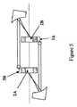
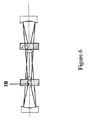
下記は、図5及び6を参照して中間エネルギー構成を述べる。100mJのオーダのエネルギーレベルに対して、例えば、レーザダイオードの40個のアレイ3が用いられる。これらの40個のアレイは、端から端までに配置されて2つのロッド2A、2Bをポンピングする5個のアレイからなる8個のスタックに分配される。2つのロッドは熱負荷を分配する長所を有する。4つのサブミラーが装置の各側部に配置されている。図5にはその内の2つだけが示されている。スタックの対角線の寸法が励起される直径を定める。1.2mmだけ分離されたアレイと共に、0.36のミラー拡大が要求される。30mmの焦点距離を有する放物面ミラーと共に、アレイからミラーの焦点までの距離xが83mmであり、第2の画像から焦点面までの距離x’が11mmである。システムの軸に関してサブミラーの傾き角αの角度は40mmの王環状のもの直径に対して約5°である。
The following describes the intermediate energy configuration with reference to FIGS. For an energy level on the order of 100 mJ, for example, 40
王環状のものの直径は、ビームの軌跡が各サブミラー内に完全に含まれるように計算される。 The diameter of the royal ring is calculated so that the beam trajectory is completely contained within each submirror.
Claims (11)
少なくとも1つのレーザビームを放射可能な、少なくとも1つのダイオードのアレイによって形成された少なくとも1つのレーザダイオード(3、3A、3B)と、
平行になったレーザビームを生成可能な前記レーザビームを平行にする手段と、
前記レーザビームを前記レーザ増幅媒質(2)の上に焦点を合わせる手段(4、4A、4B)であって、前記焦点を合わせる手段は少なくとも1つのミラーを有しており、前記ミラーは前記平行になったレーザビームが前記増幅媒質に向かって反射されるように配置されている、手段と、
を有しており、
前記ミラーは、それぞれが前記ダイオードのアレイに関連している、複数の同一のサブミラーに分かれていることを特徴とする装置。 An apparatus for longitudinally pumping a laser amplifying medium (2),
At least one laser diode (3, 3A, 3B) formed by an array of at least one diode capable of emitting at least one laser beam;
Means for collimating said laser beam capable of producing a collimated laser beam;
Means (4, 4A, 4B) for focusing the laser beam on the laser amplifying medium (2), wherein the means for focusing comprises at least one mirror, the mirror being the parallel Means arranged to reflect the laser beam into the amplification medium;
Have
The apparatus is characterized in that the mirror is divided into a plurality of identical submirrors, each associated with the array of diodes.
Applications Claiming Priority (2)
| Application Number | Priority Date | Filing Date | Title |
|---|---|---|---|
| FR0650339A FR2896921B1 (en) | 2006-01-31 | 2006-01-31 | DEVICE FOR LONGITUDINAL PUMPING OF A LASER MEDIUM |
| PCT/FR2007/000143 WO2007088263A1 (en) | 2006-01-31 | 2007-01-25 | Device for longitudinal pumping of a laser medium |
Publications (2)
| Publication Number | Publication Date |
|---|---|
| JP2009525592A true JP2009525592A (en) | 2009-07-09 |
| JP2009525592A5 JP2009525592A5 (en) | 2010-03-11 |
Family
ID=36603370
Family Applications (1)
| Application Number | Title | Priority Date | Filing Date |
|---|---|---|---|
| JP2008551824A Pending JP2009525592A (en) | 2006-01-31 | 2007-01-25 | Apparatus for longitudinal pumping of laser media |
Country Status (5)
| Country | Link |
|---|---|
| US (1) | US20100014547A1 (en) |
| EP (1) | EP1979998A1 (en) |
| JP (1) | JP2009525592A (en) |
| FR (1) | FR2896921B1 (en) |
| WO (1) | WO2007088263A1 (en) |
Cited By (3)
| Publication number | Priority date | Publication date | Assignee | Title |
|---|---|---|---|---|
| JP2015515150A (en) * | 2012-04-26 | 2015-05-21 | コーニンクレッカ フィリップス エヌ ヴェ | Optically pumped solid state laser device with self-aligned pump optics |
| JP2016503957A (en) * | 2012-12-11 | 2016-02-08 | コーニンクレッカ フィリップス エヌ ヴェKoninklijke Philips N.V. | Optically pumped solid-state laser device having self-arranged pumping optical system and high gain |
| JP2016535935A (en) * | 2013-10-30 | 2016-11-17 | コーニンクレッカ フィリップス エヌ ヴェKoninklijke Philips N.V. | Laser device including optical pump extended cavity laser |
Families Citing this family (9)
| Publication number | Priority date | Publication date | Assignee | Title |
|---|---|---|---|---|
| CN101414728B (en) * | 2008-07-25 | 2010-06-02 | 华中科技大学 | Disc piece solid laser |
| RU2517963C1 (en) * | 2010-04-19 | 2014-06-10 | Хуачжун Юниверсити Оф Сайенс Энд Текнолоджи | Disc-shaped solid laser |
| WO2013013382A1 (en) * | 2011-07-25 | 2013-01-31 | 华中科技大学 | Homogenized rod based multi-pump disc solid-state laser |
| DE102011054024B4 (en) * | 2011-09-28 | 2014-10-09 | Deutsches Zentrum für Luft- und Raumfahrt e.V. | Infrared laser amplifier system |
| FR2987467B1 (en) * | 2012-02-27 | 2016-12-09 | Somfy Sas | METHODS FOR CONTROLLING AND CONFIGURING A DOMOTIC INSTALLATION AND DOMOTIC INSTALLATION USING THESE METHODS |
| CN102684051B (en) * | 2012-04-25 | 2014-04-09 | 华中科技大学 | Disc laser amplifier |
| BR112014026319A2 (en) * | 2012-04-26 | 2017-06-27 | Koninklijke Philips Nv | optically pulsed vertical cavity surface-emitting laser device |
| CN103050877B (en) * | 2012-12-20 | 2014-10-29 | 华中科技大学 | Splicing technology-based compact type multi-disc tandem-connection solid laser |
| US11402617B2 (en) | 2018-07-12 | 2022-08-02 | Clark Wagner | System and method for generating white light for projectors |
Citations (2)
| Publication number | Priority date | Publication date | Assignee | Title |
|---|---|---|---|---|
| JPH02185082A (en) * | 1989-01-12 | 1990-07-19 | Asahi Glass Co Ltd | Laser diode-excited solid state laser |
| DE102004012014A1 (en) * | 2004-03-11 | 2005-10-13 | Osram Opto Semiconductors Gmbh | Surface emitting laser with semiconductor chip, resonator mirror outside chip and at least one optical pumping device of chip, with pumping device containing pump laser beam shaper, reversing element and concave mirror on common platform |
Family Cites Families (5)
| Publication number | Priority date | Publication date | Assignee | Title |
|---|---|---|---|---|
| US5553088A (en) * | 1993-07-02 | 1996-09-03 | Deutsche Forschungsanstalt Fuer Luft- Und Raumfahrt E.V. | Laser amplifying system |
| US6285702B1 (en) * | 1999-03-05 | 2001-09-04 | Coherent, Inc. | High-power external-cavity optically-pumped semiconductor laser |
| US6393038B1 (en) * | 1999-10-04 | 2002-05-21 | Sandia Corporation | Frequency-doubled vertical-external-cavity surface-emitting laser |
| DE10054289A1 (en) * | 2000-11-02 | 2002-02-28 | Rofin Sinar Laser Gmbh | Solid body laser with laser intensifier for intensifying oscillator beams produced from resonator uses sheet of crystal as intensifier medium for intensifying oscillator beam emerging from resonator |
| DE10338417B3 (en) * | 2003-08-18 | 2005-05-25 | Els Elektronik Laser System Gmbh | Laser with laser amplifier with a disk-shaped active medium |
-
2006
- 2006-01-31 FR FR0650339A patent/FR2896921B1/en not_active Expired - Fee Related
-
2007
- 2007-01-25 JP JP2008551824A patent/JP2009525592A/en active Pending
- 2007-01-25 US US12/223,229 patent/US20100014547A1/en not_active Abandoned
- 2007-01-25 WO PCT/FR2007/000143 patent/WO2007088263A1/en active Application Filing
- 2007-01-25 EP EP07730861A patent/EP1979998A1/en not_active Ceased
Patent Citations (2)
| Publication number | Priority date | Publication date | Assignee | Title |
|---|---|---|---|---|
| JPH02185082A (en) * | 1989-01-12 | 1990-07-19 | Asahi Glass Co Ltd | Laser diode-excited solid state laser |
| DE102004012014A1 (en) * | 2004-03-11 | 2005-10-13 | Osram Opto Semiconductors Gmbh | Surface emitting laser with semiconductor chip, resonator mirror outside chip and at least one optical pumping device of chip, with pumping device containing pump laser beam shaper, reversing element and concave mirror on common platform |
Cited By (3)
| Publication number | Priority date | Publication date | Assignee | Title |
|---|---|---|---|---|
| JP2015515150A (en) * | 2012-04-26 | 2015-05-21 | コーニンクレッカ フィリップス エヌ ヴェ | Optically pumped solid state laser device with self-aligned pump optics |
| JP2016503957A (en) * | 2012-12-11 | 2016-02-08 | コーニンクレッカ フィリップス エヌ ヴェKoninklijke Philips N.V. | Optically pumped solid-state laser device having self-arranged pumping optical system and high gain |
| JP2016535935A (en) * | 2013-10-30 | 2016-11-17 | コーニンクレッカ フィリップス エヌ ヴェKoninklijke Philips N.V. | Laser device including optical pump extended cavity laser |
Also Published As
| Publication number | Publication date |
|---|---|
| EP1979998A1 (en) | 2008-10-15 |
| FR2896921B1 (en) | 2010-06-04 |
| FR2896921A1 (en) | 2007-08-03 |
| US20100014547A1 (en) | 2010-01-21 |
| WO2007088263A1 (en) | 2007-08-09 |
Similar Documents
| Publication | Publication Date | Title |
|---|---|---|
| JP2009525592A (en) | Apparatus for longitudinal pumping of laser media | |
| US7773653B2 (en) | Diode laser arrangement and associated beam shaping unit | |
| JP3589299B2 (en) | Beam shaping device | |
| JP6547072B2 (en) | Wavelength beam combining laser system utilizing a prism for beam quality improvement and bandwidth reduction | |
| US7277229B2 (en) | Linear light beam generating optical system | |
| JP5330801B2 (en) | Laser gain medium, laser oscillator and laser amplifier | |
| KR101702246B1 (en) | Laser beam amplification by homogenous pumping of an amplification medium | |
| JPH05509179A (en) | high energy light source | |
| US8761223B2 (en) | Laser apparatuses with large-number multi-reflection pump systems | |
| US8439523B2 (en) | Laser energy source device | |
| JP2009525592A5 (en) | ||
| EP2342597B1 (en) | Interleaving laser beams | |
| JP2006222399A (en) | Semiconductor laser device | |
| JP7153862B2 (en) | Laser system with stepped slow-axis collimator | |
| JP7296605B2 (en) | Systems and methods for alignment of wavelength beam-combining resonators | |
| CN102738705A (en) | Diode laser | |
| JPH09307161A (en) | Semiconductor laser excitation solid-state laser device | |
| JP4347467B2 (en) | Concentrator | |
| JPH1168197A (en) | Solid laser device excited by semiconductor laser | |
| JPH0983048A (en) | Solid state laser | |
| JP2000277837A (en) | Solid state laser device | |
| JPH07287189A (en) | Optical path changer and laser device using the same | |
| US20230178966A1 (en) | Laser module with beam rotator | |
| JP7453328B2 (en) | Conversion device for laser radiation | |
| CN109494551B (en) | Disc laser |
Legal Events
| Date | Code | Title | Description |
|---|---|---|---|
| A521 | Written amendment |
Free format text: JAPANESE INTERMEDIATE CODE: A523 Effective date: 20100120 |
|
| A621 | Written request for application examination |
Free format text: JAPANESE INTERMEDIATE CODE: A621 Effective date: 20100120 |
|
| A977 | Report on retrieval |
Free format text: JAPANESE INTERMEDIATE CODE: A971007 Effective date: 20120316 |
|
| A131 | Notification of reasons for refusal |
Free format text: JAPANESE INTERMEDIATE CODE: A131 Effective date: 20120619 |
|
| A02 | Decision of refusal |
Free format text: JAPANESE INTERMEDIATE CODE: A02 Effective date: 20121113 |