JP2009525075A - Apparatus and method for attaching rod to spine - Google Patents
Apparatus and method for attaching rod to spine Download PDFInfo
- Publication number
- JP2009525075A JP2009525075A JP2008552525A JP2008552525A JP2009525075A JP 2009525075 A JP2009525075 A JP 2009525075A JP 2008552525 A JP2008552525 A JP 2008552525A JP 2008552525 A JP2008552525 A JP 2008552525A JP 2009525075 A JP2009525075 A JP 2009525075A
- Authority
- JP
- Japan
- Prior art keywords
- anchor
- rod
- catch
- arms
- arm
- Prior art date
- Legal status (The legal status is an assumption and is not a legal conclusion. Google has not performed a legal analysis and makes no representation as to the accuracy of the status listed.)
- Pending
Links
Images


Classifications
-
- A—HUMAN NECESSITIES
- A61—MEDICAL OR VETERINARY SCIENCE; HYGIENE
- A61B—DIAGNOSIS; SURGERY; IDENTIFICATION
- A61B17/00—Surgical instruments, devices or methods, e.g. tourniquets
- A61B17/56—Surgical instruments or methods for treatment of bones or joints; Devices specially adapted therefor
- A61B17/58—Surgical instruments or methods for treatment of bones or joints; Devices specially adapted therefor for osteosynthesis, e.g. bone plates, screws, setting implements or the like
- A61B17/68—Internal fixation devices, including fasteners and spinal fixators, even if a part thereof projects from the skin
- A61B17/70—Spinal positioners or stabilisers ; Bone stabilisers comprising fluid filler in an implant
- A61B17/7001—Screws or hooks combined with longitudinal elements which do not contact vertebrae
- A61B17/7032—Screws or hooks with U-shaped head or back through which longitudinal rods pass
-
- A—HUMAN NECESSITIES
- A61—MEDICAL OR VETERINARY SCIENCE; HYGIENE
- A61B—DIAGNOSIS; SURGERY; IDENTIFICATION
- A61B17/00—Surgical instruments, devices or methods, e.g. tourniquets
- A61B17/56—Surgical instruments or methods for treatment of bones or joints; Devices specially adapted therefor
- A61B17/58—Surgical instruments or methods for treatment of bones or joints; Devices specially adapted therefor for osteosynthesis, e.g. bone plates, screws, setting implements or the like
- A61B17/68—Internal fixation devices, including fasteners and spinal fixators, even if a part thereof projects from the skin
- A61B17/70—Spinal positioners or stabilisers ; Bone stabilisers comprising fluid filler in an implant
- A61B17/7001—Screws or hooks combined with longitudinal elements which do not contact vertebrae
- A61B17/7032—Screws or hooks with U-shaped head or back through which longitudinal rods pass
- A61B17/7034—Screws or hooks with U-shaped head or back through which longitudinal rods pass characterised by a lateral opening
Abstract
ロッドを脊椎部に接続する接続装置およびその方法を提供する。本装置は、アンカーの近位端に取り付けられた受け部を含み得る。受け部は、ロッドを収容できるサイズの受け止め部を備え、そのサイズは開位置と閉位置との間において調節可能である。1つ以上の部材が受け部に取り付けられ、受け止め部のサイズを調節する。一部の実施形態において、移動可能部材は、回転され得、および/または回転可能であり得、アンカーに対して異なる角度の位置にてロッドを収容する。
【選択図】図1A connecting device and method for connecting a rod to a spine are provided. The device can include a receptacle attached to the proximal end of the anchor. The receiving portion includes a receiving portion of a size that can accommodate the rod, and the size is adjustable between an open position and a closed position. One or more members are attached to the receiver to adjust the size of the receiver. In some embodiments, the movable member can be rotated and / or rotatable to house the rod at different angular positions relative to the anchor.
[Selection] Figure 1
Description
本発明は、一般にロッドを配置する方法および装置に関し、より詳細には、様々な方向にて脊椎ロッドを受け取り、そのロッドを脊椎部へ接続する装置および方法に関する。 The present invention relates generally to a method and apparatus for positioning a rod, and more particularly to an apparatus and method for receiving a spinal rod in various directions and connecting the rod to the spine.
脊椎は、頸部、胸部、腰部、および仙尾部を含む4つの領域に分けられる。頸部はC1−C7として識別される上から7個の脊椎部を含む。胸部はT1−T12として識別される次の12個の脊椎部を含む。腰部はL1−L5として識別される5個の脊椎部を含む。仙尾部は仙骨および尾骨を形成する9個の結合した脊椎部を含む。脊柱の脊椎部は、頸部の湾曲、胸部の湾曲、および腰仙部の湾曲を含む湾曲した形状にて配置されている。脊椎ロッドはこれらの領域のうちの1つ以上において、脊椎部を支持および配置するために埋め込むことができる。ロッドは脊柱の一区分に沿って延び、脊柱の湾曲に従うように湾曲した形状を有している。しばしば2つ以上のロッドが接続され、脊椎部を支持および配置するように組み合わされて使用される。 The spine is divided into four regions including the cervix, thorax, lumbar region, and sacral region. The neck includes the top seven vertebrae identified as C1-C7. The chest includes the following 12 vertebrae identified as T1-T12. The lumbar region includes five spine portions identified as L1-L5. The sacral region includes nine connected vertebrae that form the sacrum and coccyx. The spine of the spine is arranged in a curved shape including a neck curvature, a chest curvature, and a lumbosacral curvature. The spinal rod can be implanted to support and position the spine in one or more of these regions. The rod extends along a section of the spinal column and has a curved shape to follow the curvature of the spinal column. Often two or more rods are connected and used in combination to support and position the spine.
取り付け機構は、ロッドを脊椎部に取り付けるために用いられる。取り付け機構は脊椎部に取り付けられ、またロッドに取り付けられる。取り付け機構は通常、ロッドが配置されるべき位置で脊椎部に取り付けられる。これにより、ロッドと取り付け機構との間の取り付けが容易となる。取り付け機構はしっかりとロッドに接続されるべきであり、ロッドの位置を維持するための強いアンカーを提供するべきである。 The attachment mechanism is used to attach the rod to the spine. The attachment mechanism is attached to the spine and attached to the rod. The attachment mechanism is typically attached to the spine at the location where the rod is to be placed. Thereby, attachment between a rod and an attachment mechanism becomes easy. The attachment mechanism should be securely connected to the rod and provide a strong anchor to maintain the position of the rod.
本出願は、ロッドを脊椎部に接続するための装置および方法に関する。一実施形態において、本装置は、アンカーの近位端に取り付けられた受け部を含む。受け部は、ロッドを収容できるサイズにされた、開位置と閉位置との間において調節可能な受け止め部を備えている。1つ以上の部材が受け部に取り付けられ、受け止め部のサイズを調節する。一部の実施形態において、可動部材が回転され得、および/または回転可能であり、アンカーに対して異なる角度の位置にてロッドを収容する。 This application relates to an apparatus and method for connecting a rod to a spine. In one embodiment, the device includes a receptacle attached to the proximal end of the anchor. The receptacle includes a receptacle sized to accommodate the rod and adjustable between an open position and a closed position. One or more members are attached to the receiver to adjust the size of the receiver. In some embodiments, the movable member can be rotated and / or rotatable to house the rod at different angular positions relative to the anchor.
本出願はロッドを脊椎部に接続するための接続装置およびその方法に関する。一実施形態において、本装置は、アンカーの近位端に取り付けられた受け部を備える。受け部はロッドを配置するための受け止め部を備える。受け止め部は、開位置と閉位置との間において調節可能とすることができる。一部の実施形態において、可動部材は、異なる角度の位置においてロッドを収容できるように、回転可能および/または調節可能とすることができる。 The present application relates to a connection device and method for connecting a rod to a spine. In one embodiment, the device comprises a receptacle attached to the proximal end of the anchor. The receiving portion includes a receiving portion for arranging the rod. The catch may be adjustable between an open position and a closed position. In some embodiments, the movable member can be rotatable and / or adjustable to accommodate the rod at different angular positions.
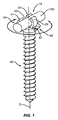
図1は、アンカー30の近位端に取り付けられた受け部20を有する装置の一実施形態を示す。受け部20は、ロッド100を収容するためにサイズ合わせをされた受け止め部15を備える。1つ以上のアーム21が受け部20に移動可能に配置され、受け止め部15のサイズを調節する。アーム21は開位置と閉位置との間で選択的に配置可能であり、受け止め部15内にロッド100を受け止め、維持する。ロック機構50は、閉位置においてアーム21を維持でき、ロッド100が受け止め部15から取れてしまうのを防ぐ。一実施形態において、受け部20は、脊椎部に挿入される前に、アンカー30と一体化して形成される。一実施形態において、受け部20の1つ以上のアーム21は、アンカー30を用いて、単一の方法にて形成される。別の実施形態において、受け部20は、アンカー30の近位端に接続される別個の要素である。受け部20のアンカー30への取り付けは、ネジ、リベットなどを含む留め具、接着剤、あるいは、はんだ付け、ろう付けなど、様々な方法にて達成することができる。一実施形態において、受け部20は、アンカー30に回転可能に接続される独立した部材である。受け部20は、アンカー30に対しておよそ360度回転可能であり、図1の矢印にて示されるように、様々な角度配置にてロッド100を収容する。
FIG. 1 illustrates one embodiment of a device having a
図2は、受け部20の近位端に配置されたアンカー30を用いた装置の一実施形態の分解図を示す。アンカー30は、遠位端と近位端との間に延びる細長形状であり、中心線Cを含む。先端32は、挿入工程の間、脊椎部に食い込むために、遠位端に配置され得る。ネジ山33は、シャフト31の一部または全体に沿って延びていてもよい。図2は、アンカーの一実施形態を示す。様々な異なるタイプのアンカー30が、受け部20とともに用いられてもよく、本出願の範囲はこれらの様々に異なるタイプのアンカーを網羅することは理解されよう。
FIG. 2 shows an exploded view of one embodiment of the device using an
受け部20は、第1の部材22および第2の部材23を備える。一実施形態において、第1の部材22は、中間にある空隙25の両側に間隔を置かれて配置されたアーム21を備える。一実施形態において、アーム21は、基部26から外側に延び、基部26に固定されて取り付けられる。別の実施形態において、アーム21は、基部26に対して可動に取り付けられる。凹部24は、アーム21の間の基部26の上表面内に配置されてもよい。一実施形態において、凹部24は、下側端が上側端よりも大きいダブテール形状(dovetail shape)である。
一実施形態において、アーム21は、アンカー30と単一の方法にて一体的に形成される。本実施形態において、アンカー30の近位端はさらに、アンカー30を脊椎部に取り付けるための駆動工具を受けるための接続具を備えてもよい。接続具は、アレンキードライバー、フィリップスのスクリュードライバー、クロスポイント スクリュードライバー、フラットヘッド スクリュードライバー、およびスターポイント スクリュードライバーなど、様々な異なる駆動工具に対応し得る。
The receiving
In one embodiment,
図2の実施形態に示されるように、第2の部材23は、アーム21およびプラットホーム27を備える。プラットホーム27は、凹部24内に滑り込んで嵌合し基部26に沿った横方向への移動を可能にする幅を有する。。一実施形態において、プラットホーム27は、より大きい下面およびより小さい上面を有し、凹部27のダブテール形状を補完する。ダブテール形状は第1の部材22に対して第2の部材23が横方向に滑動することを可能にし、第2の部材23が凹部27から上方へ外れるのを防ぐ。一実施形態において、1つ以上の延長部28は、プラットホーム27から横方向外側に延びており、凹部24内のレセプタクル29内に嵌合する。レセプタクル29は側方に設けられる壁によって画定されており、第2の部材23が第1の部材22から外れるのを防ぐ。
As shown in the embodiment of FIG. 2, the
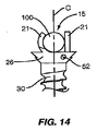
アーム21は、様々な形状およびサイズを有してもよい。一実施形態において、図2に示されるように、アーム21は、ロッド100の形状と一致するように、湾曲した形状を有する。別の実施形態において、図5に示されるように、アーム21は直線形状を有する。一実施形態において、図14に示されるように、アーム21は異なる形状およびサイズを有する。受け部20はさらに、異なる数のアーム21を含んでもよい。図2の実施形態において、第1の部材22は、2つのアームを含み、第2の部材23は単一のアーム21を含む。図12の実施形態において、各部材22、23は2つのアーム21を含む。アーム21はオフセットされていてもよく、または一直線に配置されていてもよい。別の実施形態において、図13に示されるように、アーム21は実質的に同じサイズおよび同じ形状を有し、空隙25を含まない。
The
一実施形態において、第1の部材22のアーム21は、第2の部材23のアーム21からオフセットされており、第2の部材23のアーム21は空隙25と位置を合わせて配置される。一実施形態において、第2の部材23のアーム21の幅が空隙25の幅よりも狭いので、完全なオフセットとなる。別の実施形態においては、アーム21間に部分的な重複部が存在する。第2の部材23のアーム21が空隙25よりも広い幅を含む場合、または第2の部材23のアーム21が空隙25と正しく位置合わせされていない場合、部分的な重複が生じ得る。オフセットの構成は、アーム21によってロッド100に適用される力はゼロとなる。オフセットはさらに、保持力を広い面積に拡散させ、ロッド100の折り曲げを防ぐ。
In one embodiment, the
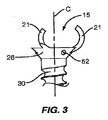
図3は、基部26に取り付けられた第2の部材23を示し、プラットホーム27は凹部24内に配置されている。一実施形態において、プラットホーム27の上面は、基部26の表面と実質的に同一平面である。他の実施形態において、プラットホーム27は基部26の水平面の上方に延びているか、または基部26の水平面の下方に位置される。受け止め部15はアーム21の間に形成される。図3は開位置を示しており、アーム21はロッド100を受け止めるために、広く間隔を置かれている。
FIG. 3 shows the
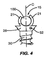
図4は、閉位置におけるアーム21を示す。アーム21間の間隔は閉位置において変化し得る。一実施形態において、アーム21はロッド100と接触する。別の実施形態において、アーム21はロッド100から間隔を置いて離れている。図4に示されるように、第2の部材23は第1の部材22に対して横方向に移動され、受け止め部15のサイズを縮小し、アーム21をロッド100と接触するように配置する。本実施形態において、アーム21は、少なくともロッド100の周囲を部分的に延びる長さを有し、アーム21間の開口部はロッド100の幅よりも小さく、ロッド100が抜けてしまうのを防ぐ。
FIG. 4 shows the
一実施形態において、受け止め部15は、アンカー30の中心線Cが受け止め部15を通って延びるように、アンカー30と位置合わせされている。図4に示されるように、ロッド100は、アーム21が閉位置にある場合、中心線C上に配置される。
In one embodiment, the
ロック機構50は第2の部材23の位置を固定する。ロック機構50は、開位置または閉位置、あるいはそれらの間の位置において、第2の部材23を固定する。様々に異なるロック機構50が活用されてもよい。図1は、第2の部材23の裏側の位置にて、凹部24内に挿入されたブロック51を含む一実施形態を示す。ブロック51は、凹部24に沿って、閉位置から開位置へ、第2の部材23が移動するのを防ぐ。一実施形態において、留め具が凹部24内のブロック51に取り付けられる。別の実施形態において、ブロック51は、凹部24内のレセプタクル29内に嵌合する延長部を有する。
The
図2及び図3は、ロック機構50の別の実施形態を示す。留め具52は、第1の部材22内の開口内に延び、凹部24内に配置された第2の部材23と接触する。一実施形態において、留め具52は第2の部材23と接触し、凹部24の壁に対して第2の部材23を押し付け、それにより位置を維持する。ロック機構50の別の実施形態は図2に示され、第2の部材23のプラットホーム27を通って延びる開口53を含む。留め具(図示されず)は開口53を通って延び、第1の部材22と接触し、第2の部材23の位置を維持する。一実施形態において、凹部24内に位置する開口(図示されず)は、留め具52の遠位端を受け止める。
2 and 3 show another embodiment of the
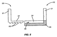
ロック機構50はさらに、図5に示されるラチェット機構をさらに含んでもよい。第1の部材22は、凹部24へと延びる1つ以上のラチェット部材56を含む。ラチェット部材56は、延長位置と奥の位置との間で移動可能である。第2の部材23は、プラットホーム27の下面上に位置する傾斜した歯55を含む。第2の部材23の、凹部24に沿った内側への動きによって、歯55がラチェット部材56に対して滑動する。ラチェット部材56は凹部24の中に向かって下方へ圧迫され、第2の部材23が凹部24に沿って滑動することを可能にする。歯55の傾斜方向は、閉位置への、内側への動きを提供するが、外側への動きを妨げる。一実施形態において、ラチェット部材56と動作可能なように接続された解放機構(図示されず)は、部材56を奥の位置に移動させ、第2の部材23を解放することを可能にする。別の実施形態において、ラチェット部材56は静止しており、歯55は、凹部24内のプラットホーム27が移動する間、弾性的に変形する。歯55の形状は、閉位置への移動を可能にし、開位置への移動を阻止する。
The
一実施形態において、部材22および23のうちの一方が、アンカー30に対して固定して配置され、受け止め部15の位置を一定に保たせる。別の実施形態では、受け止め部15を横方向へ移動させてロッド100を収容することを特徴とする。図6A、図6B、および図6Cは、一実施形態における構成部品を示す。図6Aに示されるように、アンカー30は、近位端に取り付けられた基部26を含む。基部26は、スロット61を形成する側壁62および底部63を含む。底部63は、アンカー30に対する様々な角度にて配置されてもよい。一実施形態において、図6Aに示されるように、底部63は実質的に中心線Cと直交する。
In one embodiment, one of the
図6Bは、空隙25によって分離された対のアーム21を有する第1の部材22を示す。第1および第2の部分64、65は、アーム21から外側に延びている。各部分64、65は、基部26のスロット61内に嵌合されるようにサイズを合わされたエッジ67を含む。部分64、65は、空隙66によって間隔を置かれている。へこみ部分68は、第1および第2の部分64、65の間に延びている。図6Cは、アーム21および外側に延びているプラットホーム27を有する第2の部材23を示す。プラットホーム27は、第1の部材22の内側のスロット67内に嵌合するエッジ68を含む。
FIG. 6B shows a
図7は、基部26上に配置された第1および第2の部材22、23を有する装置の組み立てられた図を示す。第1の部材22は、部分64、65の下端が底部63上におかれ、基部26のスロット61内に第1および第2の部分64、65の外側のスロット67が配置された状態で、配置される。第2の部材23は、第1および第2の部分64、65の間に形成された空隙66内に配置されるプラットホーム27を含む。プラットホーム27上のエッジ68は、第1および第2の部分64、65の内側のスロット67内に嵌合し、プラットホーム27の下面は、基部26のフロア63上におかれる。
FIG. 7 shows an assembled view of the apparatus having first and
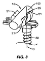
図7は、開位置における受け部20を示し、離されたアーム21は拡大された受け止め部15を形成している。一実施形態において、第1および第2の部材22、23の両方は、基部26内を移動可能であり、受け止め部15の位置を横方向に調節する。図7の方向において、中心線Cは、受け止め部15を通って延びている。部材22、23の両方が移動できるので、アンカー30から横方向へオフセットされているロッドを収容できる。図8は、閉位置における受け部20を示し、受け止め部15はサイズが縮小され、アーム21はロッド100を収容している。さらに、受け止め部15は、アンカー30の中心線Cから横方向へオフセットされている。特に、両部材22、23は基部26内を移動させられ、アンカー30から横方向へオフセットされたロッド100を収容する。ロック機構50は部材22、23の位置をロックするために備えられている。一実施形態において、ロック機構50はプラットホーム27の端部、ならびに第1および第2の部分64、65に配置されてもよく、部材22、23が基部26からはずれてしまうのを防ぐ。
FIG. 7 shows the receiving
一実施形態において、受け止め部15は、アンカー30とは反対側の上面側から開く。例として、図1および図8の実施形態は、アンカー30から離れ、上方に開く受け止め部15を有する。別の実施形態において、受け止め部15は、アンカー30の中心線Cに対して、横方向への他の角度に配置される。図9および図10は、さらに横方向に向いた、受け止め部15の開口を有する実施形態を示す。図9は、基部26に固定されて接続された第1の部材22を有する受け部20の一実施形態を示し、第1の部材22は角度を付けられている。第2の部材23は、図9に示される開位置と図10に示される閉位置との間で、基部26内に、移動可能なように配置される。図9および図10の実施形態において、受け止め部15は、アンカー20の中心線Cに位置合わせされている。横方向に角度を付けられた開口の別の実施形態において、受け止め部15はアンカーの中心線Cからオフセットされている。他の実施形態において、受け止め部15の開口の横方向への角度は、中心線Cの各側に対して、約90度の範囲に及んでいてもよい。
In one embodiment, the receiving
図9および図10に示される実施形態は、基部26上に摺動可能に配置された第2の部材23を含む。図9に示されるように、第2の部材23は、開口位置において、第1の部材22から離れる方向に摺動する。図10は閉位置を示し、第2の部材は第1の部材22の方向へ摺動し、プラットホーム27の一部は、第1の部材22のアーム21を越えて延びている。別の実施形態において、第1および第2の部材22、23の両方は、基部26に対して移動可能である。
The embodiment shown in FIGS. 9 and 10 includes a
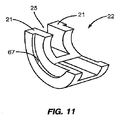
図6Aに概して示される一実施形態において、基部26は、中心線Cに対して直交しない角度にて、角度を付けられている。これにより、受け止め部15への開口は横方向に角度を付けられる。部材22、23の片方または両方は、開位置と閉位置との間において、受け止め部15のサイズを調整することができるように、基部26に沿って移動可能である。一実施形態において、部材22、23の片方または両方は、基部26内を滑り、受け止め部15のサイズを調節する。別の実施形態において、部材22、23の片方または両方は、基部26に対して回転可能である。図11は、回転可能な第2の部材22の一実施形態を示す。第2の部材22は、外縁に沿って延びているスロット67を有する湾曲形状を有する。第2の部材22は、基部26の底部63に対して嵌合し、スロット67は基部26のスロット61内に配置される。第2の部材22は基部26内で移動可能であり、受け止め部15の位置およびサイズを調節する。
In one embodiment, shown generally in FIG. 6A, the
図に示され、本明細書に記載された実施形態は、本装置および本方法の例示に過ぎない。一実施形態の要素は、他の実施形態に記載された要素と互いに代替可能であってもよい。例として、図2および図3は、固定された第1の部材22および移動可能な第2の部材23を有する装置を示す。他の実施形態は、移動可能な第1の部材22および固定された第2の部材23、ならびに、移動可能な第1および第2の部材22、23を特徴とする。
The embodiments shown in the figures and described herein are merely illustrative of the apparatus and method. Elements of one embodiment may be interchangeable with elements described in other embodiments. By way of example, FIGS. 2 and 3 show an apparatus having a fixed
用語「遠位」は、通常、患者の方向、あるいは、装置のユーザから離れた方向として定義される。反対に、「近位」は一般に、患者から離れ、ユーザの方を意味する。「下」、「下方」、「下側」、「上」、「上方」など、空間に関連する用語は、第2の要素に対する第1の要素の配置を説明するための、記載の簡便さのために用いられる。これらの用語は、図に示されたもの以外の異なる方位のみならず、装置の異なる方位も包含することが意図されている。さらに、「第1」、「第2」などの用語はまた、様々な要素、領域、部分などを記載するための用いられており、限定を意図したものではない。同様の用語は、記載を通して同様の要素を参照する。 The term “distal” is usually defined as the direction of the patient or away from the user of the device. Conversely, “proximal” generally means away from the patient and towards the user. Terms related to space, such as “lower”, “lower”, “lower”, “upper”, “upper”, are described for convenience in describing the placement of the first element relative to the second element. Used for. These terms are intended to encompass not only different orientations other than those shown in the figures, but also different orientations of the device. Further, terms such as “first”, “second” and the like are also used to describe various elements, regions, portions, etc., and are not intended to be limiting. Like terms refer to like elements throughout the description.
本明細書にて用いられるように、「有する」、「からなる」、「含む」、「備える」などの用語は、記載された要素または特徴の存在を示す、限定のない用語であり、さらなる要素または特徴を排除しない。「a」、「an」、「the」などの冠詞は、文脈が別段の意味を明らかに示さない限り、複数のみならず、単数も含むことが意図されている。 As used herein, terms such as “having”, “consisting of”, “including”, “comprising” are non-limiting terms indicating the presence of the described element or feature, and Do not exclude elements or features. Articles such as “a”, “an”, “the” are intended to include the singular as well as the plural unless the context clearly indicates otherwise.
本発明は、本発明の範囲および本質的な特性から逸脱することなく、本明細書において説明された記載以外の、特定の方法において実行されてもよい。本発明の実施形態は、それゆえ、あらゆる意味において、例示として考慮されるべきであり、限定を付すものではなく、添付の請求の範囲の意味および等価物の範囲内から由来するあらゆる変更は、本発明に包含されていることが意図されている。 The present invention may be implemented in specific ways other than those described herein without departing from the scope and essential characteristics of the invention. The embodiments of the present invention are therefore to be considered in all respects as illustrative and not restrictive, and all modifications coming from within the meaning and equivalent scope of the appended claims are not intended. It is intended to be encompassed by the present invention.
Claims (29)
遠位端と近位端との間に延びる中心線を有するアンカーと、
前記近位端に接続され、前記ロッドを受け止めるための受け止め部を形成する、オフセットされた第1および第2のアームとを備え、
前記アームの距離は、拡大された距離を有する第1の位置と縮小された距離を有する第2の位置との間において調節可能であり、前記中心線は前記第1の位置と前記第2の位置の両方において前記受け止め部を通って延びている、装置。 A device for connecting a rod to the spine,
An anchor having a center line extending between the distal end and the proximal end;
Offset first and second arms connected to the proximal end and forming a catch for receiving the rod;
The distance of the arm is adjustable between a first position having an enlarged distance and a second position having a reduced distance, and the center line is the first position and the second position. A device extending through the catch in both positions.
遠位端および近位端を有するアンカーと、
前記近位端に配置され、受け止め部を形成するアームを有する第1および第2の部材であって、前記第1の部材のアームは前記第2の部材における空隙に位置合わせされる、第1および第2の部材とを備え、
前記第1および第2の部材は、前記近位端に移動可能なように接続され、前記ロッドを受け止めるための拡大されたサイズを有する第1の位置と、前記ロッドを収容するための縮小されたサイズを有する第2の位置との間における前記受け止め部のサイズを調節する、装置。 A device for connecting a rod to the spine,
An anchor having a distal end and a proximal end;
First and second members having arms disposed at the proximal end and forming a receiving portion, wherein the first member arms are aligned with a gap in the second member; And a second member,
The first and second members are movably connected to the proximal end and have a first position having an enlarged size for receiving the rod and a reduced size for receiving the rod. Adjusting the size of the catch between the second position having a different size.
遠位端および近位端を有するアンカーと、
前記近位端に接続され、基部の外側に延びる第1のアームを有する第1の部材であって、前記アームは、前記アームの間に空隙を有して間隔を置かれて配置される、第1の部材と、
前記近位端に配置され、外側に延びる第2のアームを有する第2の部材であって、前記第1の部材と対向して配置されて前記第2の部材と前記第1の部材との間に受け止め部を形成し、前記第2のアームは前記空隙と位置合わせされる、第2の部材とを備え、
前記第1および第2の部材の少なくとも1つは、前記ロッドを受け止めるための拡大されたサイズを有する第1の位置と、前記ロッドを収容するための縮小されたサイズを有する第2の位置との間において、前記受け止め部のサイズを調節するように移動可能である、装置。 A device for connecting a rod to the spine,
An anchor having a distal end and a proximal end;
A first member having a first arm connected to the proximal end and extending outside a base, the arms being spaced apart with a gap between the arms; A first member;
A second member having a second arm disposed at the proximal end and extending outward, wherein the second member is disposed to face the first member, and the second member and the first member A second member that forms a catch in between, the second arm being aligned with the gap,
At least one of the first and second members has a first position having an enlarged size for receiving the rod and a second position having a reduced size for receiving the rod. Between which the device is movable to adjust the size of the catch.
前記脊椎部に挿入されるアンカーの近位端に接続された第1および第2の部材上のアームの間隔を開けるステップと、
前記第1および第2の部材のアームの間に形成された受け止め部に前記ロッドを挿入するステップと、
前記第1および第2の部材のアームを共に移動させ、前記第1の部材のアームが前記第2の部材における空隙と位置合わせされ、オフセットの構成を形成し、前記ロッドを前記受け止め部に収容し、前記アンカーの中心線に位置合わせされる、ステップとを含む、方法。 A method of connecting a rod to the spine,
Spacing the arms on the first and second members connected to the proximal ends of the anchors inserted into the spine;
Inserting the rod into a receiving portion formed between the arms of the first and second members;
The arms of the first and second members are moved together, the arms of the first member are aligned with the gaps in the second member to form an offset configuration, and the rod is received in the receiving portion And aligning to a centerline of the anchor.
Applications Claiming Priority (2)
| Application Number | Priority Date | Filing Date | Title |
|---|---|---|---|
| US11/343,158 US7803175B2 (en) | 2006-01-30 | 2006-01-30 | Devices and methods for attaching a rod to a vertebral member |
| PCT/US2007/060604 WO2007087486A1 (en) | 2006-01-30 | 2007-01-17 | Devices and methods for attaching a rod to a vertebral member |
Publications (2)
| Publication Number | Publication Date |
|---|---|
| JP2009525075A true JP2009525075A (en) | 2009-07-09 |
| JP2009525075A5 JP2009525075A5 (en) | 2009-11-26 |
Family
ID=37908228
Family Applications (1)
| Application Number | Title | Priority Date | Filing Date |
|---|---|---|---|
| JP2008552525A Pending JP2009525075A (en) | 2006-01-30 | 2007-01-17 | Apparatus and method for attaching rod to spine |
Country Status (4)
| Country | Link |
|---|---|
| US (1) | US7803175B2 (en) |
| EP (1) | EP1983912A1 (en) |
| JP (1) | JP2009525075A (en) |
| WO (1) | WO2007087486A1 (en) |
Families Citing this family (7)
| Publication number | Priority date | Publication date | Assignee | Title |
|---|---|---|---|---|
| US7494265B2 (en) | 2006-03-01 | 2009-02-24 | Entegris, Inc. | System and method for controlled mixing of fluids via temperature |
| US8636783B2 (en) | 2006-12-29 | 2014-01-28 | Zimmer Spine, Inc. | Spinal stabilization systems and methods |
| US8197512B1 (en) * | 2008-07-16 | 2012-06-12 | Zimmer Spine, Inc. | System and method for spine stabilization using resilient inserts |
| US20100241172A1 (en) * | 2009-03-23 | 2010-09-23 | Ashok Biyani | Pedicle screw including stationary and movable members for facilitating the surgical correction of spinal deformities |
| EP2498696A4 (en) * | 2009-11-09 | 2014-09-03 | Applied Orthopaedics Llp | Apparatus for retaining bone |
| US10265104B2 (en) * | 2015-09-23 | 2019-04-23 | Deniz Ufuk Erbulut | Pedicle screw |
| US9980755B2 (en) * | 2016-03-29 | 2018-05-29 | Globus Medical, Inc. | Revision connectors, systems, and methods thereof |
Citations (2)
| Publication number | Priority date | Publication date | Assignee | Title |
|---|---|---|---|---|
| JPH1052440A (en) * | 1996-06-07 | 1998-02-24 | Robaato Read Shokai:Kk | Screw for bone fixing |
| JP2001017441A (en) * | 1999-07-02 | 2001-01-23 | Sulzer Orthopedics Ltd | Spinal column holding device |
Family Cites Families (32)
| Publication number | Priority date | Publication date | Assignee | Title |
|---|---|---|---|---|
| US3353775A (en) * | 1965-10-19 | 1967-11-21 | Atlas Electrical Fittings Co | Conduit bracket |
| US4648388B1 (en) * | 1985-11-01 | 1995-10-31 | Acromed Corp | Apparatus and method for maintaining vertebrae in a desired relationship |
| FR2645732B1 (en) * | 1989-04-13 | 1997-01-03 | Cotrel Yves | VERTEBRAL IMPLANT FOR OSTEOSYNTHESIS DEVICE |
| US5002542A (en) * | 1989-10-30 | 1991-03-26 | Synthes U.S.A. | Pedicle screw clamp |
| US5344422A (en) * | 1989-10-30 | 1994-09-06 | Synthes (U.S.A.) | Pedicular screw clamp |
| US5540689A (en) * | 1990-05-22 | 1996-07-30 | Sanders; Albert E. | Apparatus for securing a rod adjacent to a bone |
| FR2697992B1 (en) * | 1992-11-18 | 1994-12-30 | Eurosurgical | Device for attaching to a rod of an organ, in particular for spinal orthopedic instrumentation. |
| US5437670A (en) * | 1993-08-19 | 1995-08-01 | Danek Medical, Inc. | Attachment plate for top-tightening clamp assembly in a spinal fixation system |
| US5415659A (en) * | 1993-12-01 | 1995-05-16 | Amei Technologies Inc. | Spinal fixation system and pedicle clamp |
| US5662653A (en) * | 1996-02-22 | 1997-09-02 | Pioneer Laboratories, Inc. | Surgical rod-to-bone attachment |
| US5746741A (en) * | 1996-05-06 | 1998-05-05 | Tufts University | External fixator system |
| CA2264672C (en) * | 1996-10-24 | 2010-11-30 | Spinal Concepts, Inc. | Method and apparatus for spinal fixation |
| US6416515B1 (en) * | 1996-10-24 | 2002-07-09 | Spinal Concepts, Inc. | Spinal fixation system |
| DE29700737U1 (en) * | 1997-01-16 | 1997-02-27 | Halfen Gmbh & Co Kg | Clamping screw |
| US6783526B1 (en) * | 1997-05-15 | 2004-08-31 | Howmedica Osteonics Corp. | Transverse rod connector clip |
| FR2763236B1 (en) * | 1997-05-16 | 1999-10-15 | Scient X | IMPLANT FOR A VERTEBRAL HOOK TYPE OSTEOSYNTHESIS DEVICE |
| US6179838B1 (en) * | 1998-02-24 | 2001-01-30 | Daniel Fiz | Bone fixation arrangements and method |
| US6090111A (en) * | 1998-06-17 | 2000-07-18 | Surgical Dynamics, Inc. | Device for securing spinal rods |
| FR2781663B1 (en) * | 1998-07-30 | 2000-10-13 | Materiel Orthopedique En Abreg | SPINAL OSTEOSYNTHESIS DEVICE |
| US6110172A (en) * | 1998-07-31 | 2000-08-29 | Jackson; Roger P. | Closure system for open ended osteosynthesis apparatus |
| US6562038B1 (en) * | 2000-03-15 | 2003-05-13 | Sdgi Holdings, Inc. | Spinal implant connection assembly |
| CA2476335C (en) | 2002-02-11 | 2009-10-27 | Raoul Donath | Device for connecting a longitudinal member to a bone |
| FR2842724B1 (en) * | 2002-07-23 | 2005-05-27 | Spine Next Sa | VERTEBRAL FASTENING SYSTEM |
| FR2848408B1 (en) * | 2002-12-17 | 2005-08-19 | Vitatech | DEVICE WITH ANTERIOR PLATE FOR MAINTAINING THE RACHIS |
| FR2852815B1 (en) | 2003-03-26 | 2006-09-01 | Jean Pierre Lenfant | IMPLANTABLE GAME-RETRACTING DEVICE FOR POSITIONAL MAINTENANCE OF VERTEBRATES |
| WO2005037115A1 (en) | 2003-10-14 | 2005-04-28 | Eurosurgical | Device for occipital fixation |
| GB0326888D0 (en) * | 2003-11-19 | 2003-12-24 | Depuy Int Ltd | A hook |
| US7503924B2 (en) | 2004-04-08 | 2009-03-17 | Globus Medical, Inc. | Polyaxial screw |
| US7938848B2 (en) * | 2004-06-09 | 2011-05-10 | Life Spine, Inc. | Spinal fixation system |
| EP1627608B1 (en) * | 2004-08-20 | 2009-05-06 | Stryker Trauma SA | Clamp element and joint element |
| US7404818B2 (en) * | 2004-11-30 | 2008-07-29 | Warsaw Orthopedic, Inc. | Side-loading adjustable bone anchor |
| US7674277B2 (en) * | 2004-12-01 | 2010-03-09 | Warsaw Orthopedic, Inc. | Side-loading bone anchor |
-
2006
- 2006-01-30 US US11/343,158 patent/US7803175B2/en active Active
-
2007
- 2007-01-17 EP EP07710153A patent/EP1983912A1/en not_active Withdrawn
- 2007-01-17 JP JP2008552525A patent/JP2009525075A/en active Pending
- 2007-01-17 WO PCT/US2007/060604 patent/WO2007087486A1/en active Application Filing
Patent Citations (2)
| Publication number | Priority date | Publication date | Assignee | Title |
|---|---|---|---|---|
| JPH1052440A (en) * | 1996-06-07 | 1998-02-24 | Robaato Read Shokai:Kk | Screw for bone fixing |
| JP2001017441A (en) * | 1999-07-02 | 2001-01-23 | Sulzer Orthopedics Ltd | Spinal column holding device |
Also Published As
| Publication number | Publication date |
|---|---|
| US20070191843A1 (en) | 2007-08-16 |
| US7803175B2 (en) | 2010-09-28 |
| EP1983912A1 (en) | 2008-10-29 |
| WO2007087486A1 (en) | 2007-08-02 |
Similar Documents
| Publication | Publication Date | Title |
|---|---|---|
| JP2009525075A (en) | Apparatus and method for attaching rod to spine | |
| US9486248B2 (en) | Occipital plate for spinal fusion | |
| US8246623B2 (en) | Progressive reduction instrument for reduction of a vertebral rod and method of use | |
| JP5912056B2 (en) | Multi-axis pedicle screw and fixation system kit including the same | |
| US8328854B2 (en) | Cervical plate ratchet pedicle screws | |
| US9149306B2 (en) | Spinous process device | |
| US7678114B2 (en) | Vertebral implant inserter and method of use | |
| US7776070B2 (en) | Occipital plating systems and methods | |
| US8057518B2 (en) | Spanning connector for connecting a spinal fixation element and an offset bone anchor | |
| KR20100038314A (en) | Clamps used for interconnecting a bone anchor to a rod | |
| JP2010508996A (en) | Rear fixing device and method of use | |
| US20120191144A1 (en) | Instrument for reduction of a vertebral rod and method of use | |
| JP2008536584A (en) | Cam base and rod connection system and method | |
| US20080071274A1 (en) | Percutaneous Screw Assembly and Placement Method | |
| KR101537062B1 (en) | An apparatus for fixing vertebra | |
| US20130006307A1 (en) | Cross link for spinal rod system | |
| US20140088650A1 (en) | Polyaxial Connector for Spinal Fixation Systems | |
| US20080234765A1 (en) | Rod reduction methods and devices | |
| EP2713919B1 (en) | Bone screw system with connecting portion | |
| JP2009511129A (en) | Adjustable occipital plate | |
| AU2004231542A1 (en) | Spinal fixation sytem and method | |
| JP2008505740A (en) | Spinal rod insertion instrument | |
| CN1972637A (en) | Rod persuader | |
| JP5656855B2 (en) | Mobile occipital vertebral fixation system | |
| US10478233B2 (en) | Adjustable hook |
Legal Events
| Date | Code | Title | Description |
|---|---|---|---|
| A521 | Request for written amendment filed |
Free format text: JAPANESE INTERMEDIATE CODE: A523 Effective date: 20091008 |
|
| A621 | Written request for application examination |
Free format text: JAPANESE INTERMEDIATE CODE: A621 Effective date: 20091008 |
|
| A131 | Notification of reasons for refusal |
Free format text: JAPANESE INTERMEDIATE CODE: A131 Effective date: 20111222 |
|
| A977 | Report on retrieval |
Free format text: JAPANESE INTERMEDIATE CODE: A971007 Effective date: 20111222 |
|
| A601 | Written request for extension of time |
Free format text: JAPANESE INTERMEDIATE CODE: A601 Effective date: 20120322 |
|
| A602 | Written permission of extension of time |
Free format text: JAPANESE INTERMEDIATE CODE: A602 Effective date: 20120329 |
|
| A02 | Decision of refusal |
Free format text: JAPANESE INTERMEDIATE CODE: A02 Effective date: 20120813 |