JP2009524285A - Receiver using non-pilot reference channel to equalize received signal - Google Patents
Receiver using non-pilot reference channel to equalize received signal Download PDFInfo
- Publication number
- JP2009524285A JP2009524285A JP2008550377A JP2008550377A JP2009524285A JP 2009524285 A JP2009524285 A JP 2009524285A JP 2008550377 A JP2008550377 A JP 2008550377A JP 2008550377 A JP2008550377 A JP 2008550377A JP 2009524285 A JP2009524285 A JP 2009524285A
- Authority
- JP
- Japan
- Prior art keywords
- signals
- signal
- channel
- power
- received
- Prior art date
- Legal status (The legal status is an assumption and is not a legal conclusion. Google has not performed a legal analysis and makes no representation as to the accuracy of the status listed.)
- Pending
Links
- 238000000034 method Methods 0.000 claims description 51
- 238000012545 processing Methods 0.000 claims description 19
- 230000008569 process Effects 0.000 claims description 14
- 238000001914 filtration Methods 0.000 claims description 6
- 230000008929 regeneration Effects 0.000 claims 1
- 238000011069 regeneration method Methods 0.000 claims 1
- 230000003111 delayed effect Effects 0.000 abstract description 15
- 230000005540 biological transmission Effects 0.000 description 16
- 230000007480 spreading Effects 0.000 description 15
- 238000010586 diagram Methods 0.000 description 11
- 238000012549 training Methods 0.000 description 10
- 238000004364 calculation method Methods 0.000 description 8
- 238000011143 downstream manufacturing Methods 0.000 description 8
- 238000011144 upstream manufacturing Methods 0.000 description 8
- 230000006870 function Effects 0.000 description 7
- 108010003272 Hyaluronate lyase Proteins 0.000 description 2
- 238000013459 approach Methods 0.000 description 2
- 230000008901 benefit Effects 0.000 description 2
- 230000008859 change Effects 0.000 description 2
- 230000007274 generation of a signal involved in cell-cell signaling Effects 0.000 description 2
- 230000003287 optical effect Effects 0.000 description 2
- 230000009467 reduction Effects 0.000 description 2
- 230000004044 response Effects 0.000 description 2
- 210000003813 thumb Anatomy 0.000 description 2
- 238000006243 chemical reaction Methods 0.000 description 1
- 239000003795 chemical substances by application Substances 0.000 description 1
- 230000007423 decrease Effects 0.000 description 1
- 230000001934 delay Effects 0.000 description 1
- 238000013461 design Methods 0.000 description 1
- 230000005670 electromagnetic radiation Effects 0.000 description 1
- 238000011478 gradient descent method Methods 0.000 description 1
- 238000012804 iterative process Methods 0.000 description 1
- 238000002372 labelling Methods 0.000 description 1
- 239000000463 material Substances 0.000 description 1
- 230000004048 modification Effects 0.000 description 1
- 238000012986 modification Methods 0.000 description 1
- 239000013307 optical fiber Substances 0.000 description 1
- 238000005457 optimization Methods 0.000 description 1
- 230000000737 periodic effect Effects 0.000 description 1
- 230000003252 repetitive effect Effects 0.000 description 1
- 239000007787 solid Substances 0.000 description 1
Images


Classifications
-
- H—ELECTRICITY
- H04—ELECTRIC COMMUNICATION TECHNIQUE
- H04B—TRANSMISSION
- H04B1/00—Details of transmission systems, not covered by a single one of groups H04B3/00 - H04B13/00; Details of transmission systems not characterised by the medium used for transmission
- H04B1/06—Receivers
-
- H—ELECTRICITY
- H04—ELECTRIC COMMUNICATION TECHNIQUE
- H04L—TRANSMISSION OF DIGITAL INFORMATION, e.g. TELEGRAPHIC COMMUNICATION
- H04L25/00—Baseband systems
- H04L25/02—Details ; arrangements for supplying electrical power along data transmission lines
- H04L25/03—Shaping networks in transmitter or receiver, e.g. adaptive shaping networks
- H04L25/03006—Arrangements for removing intersymbol interference
- H04L25/03012—Arrangements for removing intersymbol interference operating in the time domain
- H04L25/03019—Arrangements for removing intersymbol interference operating in the time domain adaptive, i.e. capable of adjustment during data reception
- H04L25/03038—Arrangements for removing intersymbol interference operating in the time domain adaptive, i.e. capable of adjustment during data reception with a non-recursive structure
- H04L25/03044—Arrangements for removing intersymbol interference operating in the time domain adaptive, i.e. capable of adjustment during data reception with a non-recursive structure using fractionally spaced delay lines or combinations of fractionally integrally spaced taps
-
- H—ELECTRICITY
- H04—ELECTRIC COMMUNICATION TECHNIQUE
- H04B—TRANSMISSION
- H04B1/00—Details of transmission systems, not covered by a single one of groups H04B3/00 - H04B13/00; Details of transmission systems not characterised by the medium used for transmission
- H04B1/69—Spread spectrum techniques
- H04B1/707—Spread spectrum techniques using direct sequence modulation
- H04B1/7097—Interference-related aspects
-
- H—ELECTRICITY
- H04—ELECTRIC COMMUNICATION TECHNIQUE
- H04L—TRANSMISSION OF DIGITAL INFORMATION, e.g. TELEGRAPHIC COMMUNICATION
- H04L25/00—Baseband systems
- H04L25/02—Details ; arrangements for supplying electrical power along data transmission lines
- H04L25/03—Shaping networks in transmitter or receiver, e.g. adaptive shaping networks
- H04L25/03006—Arrangements for removing intersymbol interference
- H04L2025/03433—Arrangements for removing intersymbol interference characterised by equaliser structure
- H04L2025/03439—Fixed structures
- H04L2025/03445—Time domain
- H04L2025/03471—Tapped delay lines
- H04L2025/03509—Tapped delay lines fractionally spaced
-
- H—ELECTRICITY
- H04—ELECTRIC COMMUNICATION TECHNIQUE
- H04L—TRANSMISSION OF DIGITAL INFORMATION, e.g. TELEGRAPHIC COMMUNICATION
- H04L25/00—Baseband systems
- H04L25/02—Details ; arrangements for supplying electrical power along data transmission lines
- H04L25/03—Shaping networks in transmitter or receiver, e.g. adaptive shaping networks
- H04L25/03006—Arrangements for removing intersymbol interference
- H04L2025/03592—Adaptation methods
- H04L2025/03598—Algorithms
- H04L2025/03611—Iterative algorithms
- H04L2025/03617—Time recursive algorithms
-
- H—ELECTRICITY
- H04—ELECTRIC COMMUNICATION TECHNIQUE
- H04L—TRANSMISSION OF DIGITAL INFORMATION, e.g. TELEGRAPHIC COMMUNICATION
- H04L25/00—Baseband systems
- H04L25/02—Details ; arrangements for supplying electrical power along data transmission lines
- H04L25/03—Shaping networks in transmitter or receiver, e.g. adaptive shaping networks
- H04L25/03006—Arrangements for removing intersymbol interference
- H04L2025/03592—Adaptation methods
- H04L2025/03598—Algorithms
- H04L2025/03681—Control of adaptation
- H04L2025/03687—Control of adaptation of step size
Abstract
1実施形態では、受信機が基準発生器および主等化器を有する。基準発生器は1つまたはそれ以上のパイロット基準信号を用いて受信信号を等化する。次いで、基準発生器は等化信号の1つまたはそれ以上の所定のデータチャネルをデコードし、各デコードチャネルのデータについて硬決定を行い、各デコードチャネルの元のコードシーケンスを再生する。主等化器は、1つまたはそれ以上のパイロット信号と一緒に、各再エンコードチャネルを追加の基準信号として用いて、受信信号の時間遅延されたバージョンを等化する。代替実施形態では、受信機は、再エンコードチャネルの数およびそれらチャネルの電力に基づいてルックアップテーブルから最適なステップサイズを選択するステップサイズ発生器を有してもよい。次いで、ステップサイズが主等化器によって再エンコードチャネルと一緒に用いられて、時間遅延された受信信号を等化する。In one embodiment, the receiver has a reference generator and a main equalizer. The reference generator equalizes the received signal using one or more pilot reference signals. The reference generator then decodes one or more predetermined data channels of the equalization signal, makes a hard decision on the data of each decode channel, and regenerates the original code sequence of each decode channel. The main equalizer equalizes the time delayed version of the received signal using each re-encoded channel as an additional reference signal along with one or more pilot signals. In an alternative embodiment, the receiver may have a step size generator that selects an optimal step size from a lookup table based on the number of re-encoding channels and the power of those channels. The step size is then used by the main equalizer along with the re-encode channel to equalize the time delayed received signal.
Description
(関連出願の相互参照)
本願は代理人ドケット番号Banna3−2−2号である2006年1月12日出願の仮出願第60/758,514号の出願日の利益を主張し、同仮出願の教示を参照により本願に援用する。
(Cross-reference of related applications)
This application claims the benefit of the filing date of provisional application No. 60 / 758,514, filed on January 12, 2006, with agent docket number Banna 3-2-2, and the teachings of that provisional application are incorporated herein by reference. Incorporate.
発明の分野
本発明は信号処理受信機に関し、更に具体的には、当該受信機によって受信された信号を等化することに関する。
The present invention relates to signal processing receivers, and more specifically to equalizing signals received by the receiver.
関連出願の説明
先行技術の受信機の概要
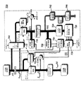
図1はパイロットチャネルを用いて受信信号を等化(例えば、初期化(「トレイン」)および追跡)する先行技術の受信機100の1実施のブロック図を示している。受信機100は、上流側処理部102、チップレート正規化最小2乗平均(NLMS)型等化器104、デスクランブラ/デスプレッダ106、および下流側処理部108を有する。上流側処理部102はアナログ/デジタル変換、ルート二乗余弦フィルタリング、または受信信号を調製して等化するための他の処理を含む事前等化処理を実行する。NLMS等化器104は上流側処理部102からデジタルデータy(i)を受信し、信号y(i)を等化して元の伝送前信号に近似させ、等化信号

NLMS等化器104は、有限インパルス応答(FIR)フィルタ110、係数更新器112、およびエラー計算器114を備える更新ループを用いてデジタル信号y(i)を等化する。FIRフィルタ110は着信デジタル信号y(i)を受信し、係数w(i)を信号y(i)に適用し、等化信号
正規化最小2乗平均法を用いた係数計算
係数w(i)は当該分野で公知の多数の方法のいずれか1つを用いて計算され得る。図1の実施形態によれば、係数更新器112は信号y(i)およびエラー信号e(i)を受信し、正規化最小2乗平均(NLMS)法を用いて新しい係数w(i+1)を計算する。NLMS法は最小2乗平均(LMS)法の変法である。ここで、新しい係数w(i+1)の各々は以下の式(1)のように計算される:
wLMS(i+1)=wLMS(i)−μ∇wE[|e(i)2|] (1)
(式中、∇wはエラー信号e(i)の期待値E[|e(i)|2]の勾配であり、μは更新ステップサイズである。)。
Coefficient Calculation Using Normalized Least Mean Square Method The coefficient w (i) can be calculated using any one of a number of methods known in the art. According to the embodiment of FIG. 1, the
w LMS (i + 1) = w LMS (i) -μ∇ w E [| e (i) 2 |] (1)
(Where w is the slope of the expected value E [| e (i) | 2 ] of the error signal e (i) and μ is the update step size).
期待値E[|e(i)|2](すなわち、平均2乗誤差(MSE))は「誤差特性曲面」として表すことができる。曲面上の極小値によって表される最小2乗平均誤差(MMSE)に達するために、勾配降下法を用いて全曲面をステップする。式(1)のMSEがMMSEに近付くに従って、タップ重みw(i)の精度は上がる。式(1)の推定値の代わりに瞬間的な推定値を代入すれば、以下のような式(2)の特定のLMS計算が得られる:
wLMS=(i+1)=wLMS(i)−Δy(i)e*(i) (2)
式中、小さなスカラーがステップサイズΔとして選択され、e*(i)はエラー信号e(i)の複素共役である。NLMS係数wNLMS(i+1)を得るために、LMS式(2)を正規化して以下のように式(3)を生成する:
w LMS = (i + 1) = w LMS (i) −Δy (i) e * (i) (2)
Where a small scalar is selected as the step size Δ, and e * (i) is the complex conjugate of the error signal e (i). To obtain the NLMS coefficient w NLMS (i + 1), LMS equation (2) is normalized to produce equation (3) as follows:
エラー計算
元の伝送前信号を概算する際のNLMS等化器104の精度は、エラー信号e(i)によって測定される。したがって、エラーe(i)が小さいと、等化器性能が改善したことを表す。エラー信号e(i)はFIRフィルタ110の等化出力
典型的な伝送においては、伝送信号の大部分は受信機によって知られていない。しかし、既知のビットシーケンスを含んだパイロット信号z(i)が、トレーニングおよびトラッキングのために伝送され得る。式(4)の基準x(i)の代わりにパイロットz(i)を代入すれば、式(5)に示されるようにエラー信号e’(i)が得られる:
第3世代パートナーシッププロジェクト(3GPP)用途においては、受信機は一般的なパイロットチャネル(CPICH)を用いて等化される。また、CPICHは、受信機によって知られている、スクランブルシーケンスcscram(i)および拡散シーケンスcch(i)を有する。3GPPリリース5コンパチブル受信機の場合、1次パイロットチャネル(PCPICH)、2次パイロットチャネル(SCPICH)のいずれか、またはこの両方が、継続的なトラッキングおよびトレーニングに使用され得る。SCPICHはPCPICHとは異なる拡散シーケンスおよびスクランブルコードを有する。
3GGPおよび他の用途でのパイロット信号電力は典型的には、総伝送電力の10%に制限される。パイロット信号は総受信信号電力の小さな部分しか表さないので、信号エラーe’(i)は決してゼロに近似しない。また、パイロットz(i)だけが勾配推定を計算する際に用いられるため、入力信号y(i)の未知のデータシンボルが、勾配雑音の原因となる。エラーe’(i)を最小化し、ひいては等化性能を上げるために、パイロット信号電力が増大され得る。しかし、パイロット信号電力を増大すれば、パイロット信号と一緒に伝送できるデータ量が低減される。 Pilot signal power in 3GGP and other applications is typically limited to 10% of the total transmitted power. Since the pilot signal represents only a small portion of the total received signal power, the signal error e '(i) never approximates zero. Also, since only pilot z (i) is used in calculating the gradient estimate, unknown data symbols in the input signal y (i) cause gradient noise. In order to minimize the error e '(i) and thus improve the equalization performance, the pilot signal power can be increased. However, if the pilot signal power is increased, the amount of data that can be transmitted together with the pilot signal is reduced.
1実施形態では、本発明は受信信号を等化する方法である。この方法は(a)1つまたはそれ以上の受信信号の第1のセットを等化して、1つまたはそれ以上の等化信号の第1のセットを発生するステップ、(b)1つまたはそれ以上の等化信号の第1のセットを処理して、受信信号の1つまたはそれ以上の非パイロットチャネルの第1のセットに相当する1つまたはそれ以上のデコードデータストリームの第1のセットを発生するステップ、(c)1つまたはそれ以上のデコードデータストリームの第1のセットから1つまたはそれ以上の基準信号を発生するステップ、および(d)1つまたはそれ以上の受信信号の第2のセットを等化して、1つまたはそれ以上の等化信号の第2のセットを発生するステップを含む。1つまたはそれ以上の等化信号の第1のセットの等化は、受信信号の少なくとも1つのパイロットチャネルに基づく。また、1つまたはそれ以上の受信信号の第2のセットの等化は、(1)少なくとも1つのパイロットチャネルおよび(2)1つまたはそれ以上のデコードデータストリームの第1のセットから発生された1つまたはそれ以上の基準信号に基づく。 In one embodiment, the present invention is a method for equalizing a received signal. The method comprises the steps of (a) equalizing a first set of one or more received signals to generate a first set of one or more equalized signals; (b) one or more The first set of equalized signals is processed to produce a first set of one or more decoded data streams corresponding to the first set of one or more non-pilot channels of the received signal. Generating, (c) generating one or more reference signals from a first set of one or more decoded data streams, and (d) a second of one or more received signals. And generating a second set of one or more equalized signals. The equalization of the first set of one or more equalized signals is based on at least one pilot channel of the received signal. Also, equalization of the second set of one or more received signals was generated from (1) at least one pilot channel and (2) the first set of one or more decoded data streams. Based on one or more reference signals.
別の実施形態では、本発明は受信信号を等化する装置である。この装置は(a)1つまたはそれ以上の受信信号の第1のセットを等化して1つまたはそれ以上の等化信号の第1のセットを発生するように適合された第1の等化器、(b)1つまたはそれ以上の等化信号の第1のセットを処理して、受信信号の1つまたはそれ以上の非パイロットチャネルの第1のセットに相当する1つまたはそれ以上のデコードデータストリームの第1のセットを発生するように適合された第1のデコーダ、(c)1つまたはそれ以上のデコードデータストリームの第1のセットから1つまたはそれ以上の基準信号を発生するように適合された基準信号発生器、および(d)1つまたはそれ以上の受信信号の第2のセットを等化して1つまたはそれ以上の等化信号の第2のセットを発生するように適合された第2の等化器を備える。1つまたはそれ以上の等化信号の第1のセットの等化は受信信号の少なくとも1つのパイロットチャネルに基づく。また、1つまたはそれ以上の受信信号の第2のセットの等化は、(1)少なくとも1つのパイロットチャネルおよび(2)1つまたはそれ以上のデコードデータストリームの第1のセットから発生された1つまたはそれ以上の基準信号に基づく。 In another embodiment, the present invention is an apparatus for equalizing a received signal. The apparatus includes: (a) a first equalization adapted to equalize a first set of one or more received signals to generate a first set of one or more equalized signals. (B) processing one first set of one or more equalized signals to represent one or more corresponding to the first set of one or more non-pilot channels of the received signal; A first decoder adapted to generate a first set of decoded data streams; (c) generating one or more reference signals from the first set of one or more decoded data streams; A reference signal generator adapted to, and (d) equalize the second set of one or more received signals to generate a second set of one or more equalized signals Adapted second equalizer Provided. The equalization of the first set of one or more equalized signals is based on at least one pilot channel of the received signal. Also, equalization of the second set of one or more received signals was generated from (1) at least one pilot channel and (2) the first set of one or more decoded data streams. Based on one or more reference signals.
更に別の実施形態では、本発明は受信機において受信信号を等化する方法である。この方法はフィルタ係数のセットに基づいて受信信号を濾波して、等化信号を発生することを含む。フィルタ係数のセットは(1)エラー信号を計算すること、および(2)エラー信号に基づいてフィルタ係数のセットを更新することによって適応的に発生される。このエラー信号は等化信号を、受信機によって先験的に知られているビットパターンを有する第1のチャネルを少なくとも含む1つまたはそれ以上の基準チャネルと比較することによって計算される。ここでは、第1のチャネルはパイロットチャネルとして以外の目的で受信機によって使用される。 In yet another embodiment, the present invention is a method for equalizing a received signal at a receiver. The method includes filtering the received signal based on a set of filter coefficients to generate an equalized signal. The set of filter coefficients is adaptively generated by (1) calculating an error signal and (2) updating the set of filter coefficients based on the error signal. This error signal is calculated by comparing the equalized signal with one or more reference channels including at least a first channel having a bit pattern known a priori by the receiver. Here, the first channel is used by the receiver for purposes other than as a pilot channel.
本発明の他の態様、特徴、および利点は以下の詳細な説明、添付の特許請求の範囲、および添付図面からより完全に明白となろう。それらにおいて同様の参照番号は類似するか同一の要素を示す。 Other aspects, features and advantages of the present invention will become more fully apparent from the following detailed description, the appended claims and the accompanying drawings. In the drawings, like reference numbers indicate similar or identical elements.
データ信号からの追加の基準信号の発生
図2は本発明の1実施形態の受信機200の単純化されたブロック図を示す。受信機200は受信信号から追加の基準信号を発生し、この追加の基準信号を用いて受信信号を等化するように適合されている。受信機200は、上流側処理部202、デスクランブラ/デスプレッダ206、および下流側処理部208を有しており、これらは図1の先行技術の受信機100の上流側処理部102、デスクランブラ/デスプレッダ106、および下流側処理部108に類似する。受信機200はまた、基準発生器218、主チップレート正規化最小2乗平均(NLMS)等化器204、および入力サンプル遅延バッファ216を有する。
Generating an Additional Reference Signal from a Data Signal FIG. 2 shows a simplified block diagram of a
基準発生器218は補助NLMSチップレート等化器220、デスプレッダ/デスクランブラ222、シンボル決定ブロック224、およびチップシーケンス発生器226を有する。補助NLMS等化器220は上流側処理部202からデジタル信号y(i)を受信し、(すなわち、パイロットチャネルz(i)を基準として用いる)先行技術の受信機100のNLMS等化器104と類似する様式で信号y(i)を等化し、等化信号
追加の基準信号を用いた受信信号の等化
入力サンプル遅延バッファ216が受信デジタル信y(i)を遅延し、遅延信号ydelayed(i)を主NLMS等化器204に伝送する。先行技術のNLMS等化器104と同様、主NLMS等化器204は有限インパルス応答(FIR)フィルタ210、係数更新器212、およびエラー計算器214を備えた更新ループである。FIRフィルタ210は遅延信号ydelayed(i)を受信し、係数wmain(i)を信号ydelayed(i)に適用し、等化信号
エラー信号emain(i)はパイロットz(i)および基準信号発生器218によって発生された1つまたはそれ以上の追加の基準信号vk(i)を用いて計算される。式(4)は以下のような主エラー信号emain(i)を生成するために修正される:
次いで、新しいタップ重みwmain(i+1)が、主エラー信号emain(i)および遅延着信信号ydelayed(i)を用いて、式(7)に示すように式(3)を修正することによって計算される。
等化後、拡散シーケンスおよびスクランブルコードが、デスクランブラ/デスプレッダ206によって等化信号
1つまたはそれ以上の追加の基準信号vk(i)をエラー計算に加算することによって、エラー信号emain(i)は先行技術の受信機100のエラー信号e’(i)よりも、ゼロにより近く近似する。このより正確なエラー計算により、同じステップサイズ
パイロット電力を維持し、上記のような追加の基準信号を用いることによって、伝送データ量を低減することなく、トレーニングおよびトラッキングに使用可能な有効電力を増大することができる。この電力の増大は、ビットエラーレートを低減することによって受信機の性能を改善し、したがって、受信機の全体的スループットを増大させる。他方、トレーニングおよびトラッキングに追加の基準信号を用いながら、パイロット電力を低減することができる。ここでは、パイロット電力の低減は、受信機が先行技術の受信機のものと同じビットエラーレートを維持しながら、より多くのデータを送信することを可能にする。他の実施はパイロット電力を部分的に低減するだけで、ビットエラーレートの低減およびデータ伝送速度の増大を達成することができる。 By maintaining pilot power and using additional reference signals as described above, the available power available for training and tracking can be increased without reducing the amount of transmitted data. This increase in power improves the performance of the receiver by reducing the bit error rate, and thus increases the overall throughput of the receiver. On the other hand, pilot power can be reduced while using additional reference signals for training and tracking. Here, the reduction in pilot power allows the receiver to transmit more data while maintaining the same bit error rate as that of the prior art receiver. Other implementations can achieve a reduced bit error rate and increased data transmission rate by only partially reducing pilot power.
追加の基準信号として用いてよい例示的チャネル
この発明は受信機が1つまたはそれ以上のパイロットチャネルを用いてデータ信号を等化する種々の用途で使用されてよい。そういった用途の1例が、3GPP受信機への高速ダウンリンクパケットアクセス(HSDPA)伝送である。HSDPA伝送においては、追加の基準信号を発生するのに使用し得るチャネルには、1から4個の高速共有制御チャネル(HSSCCH)、1次共有物理チャネル(PCCPCH)、高速共有データチャネル(HSPDSCH)、およびダウンリンク物理チャネル(DPCH)が挙げられる。
Exemplary Channels that may be Used as Additional Reference Signals The present invention may be used in various applications where a receiver equalizes a data signal using one or more pilot channels. One example of such an application is high speed downlink packet access (HSDPA) transmission to a 3GPP receiver. In HSDPA transmission, the channels that can be used to generate additional reference signals include 1 to 4 high speed shared control channels (HSSCCH), primary shared physical channel (PCCPCH), and high speed shared data channel (HSPDSCH). , And downlink physical channel (DPCH).
HSSCCHチャネルの少なくとも1つがHSDPA伝送中に存在するであろう。上記のように、デスクランブラ/デスプレッダ222が等化信号
SCHチャネルが伝送されないとき、PCCPCHチャネルはスロットの残りの90パーセントの間に伝送される。追加の基準信号が、HSSCCHチャネルに関して上記に用いられた方法に類似する様式でPCCPCHから生成され得る。PCCPCHは比較的大きな拡散シーケンス(すなわち、256チップ/シンボル)を有する。したがって、正確な硬決定は各PCCPCHソフトシンボルについて別々に行われてよく、主等化器204は256チップほどの小さい遅延を用いて動作できる。
When the SCH channel is not transmitted, the PCCPCH channel is transmitted during the remaining 90 percent of the slot. Additional reference signals may be generated from the PCCPCH in a manner similar to the method used above for the HSSCCH channel. PCCPCH has a relatively large spreading sequence (ie 256 chips / symbol). Thus, accurate hard decisions may be made separately for each PCCPCH soft symbol, and
HSPDSCHは比較的小さな拡散シーケンス(すなわち、約16チップ/シンボル)を有する。拡散シーケンスが小さいために、シンボル決定ブロック224は各ソフトシンボルrk(n)について別々に正確な硬決定を行うことができない恐れがある。その代わりに、シンボル決定ブロック224が多数のシンボルを受信し、周期的冗長検査を実行する。シンボルにエラーがない場合、次いでシンボル決定ブロック224は各シンボルについて硬決定を行う。このプロセスは2つまたはそれ以上の伝送時間インターバル(TTI)を要し、したがって、主等化器204は1つのTT1を超える遅延を用いて動作することに留意されたい。次いで、シンボルは元のチャネル拡散係数およびスクランブルコードを用いてチップシーケンス発生器226によってスクランブルおよび拡散されて、追加の基準vk(i)を形成する。
HSPDSCH has a relatively small spreading sequence (ie about 16 chips / symbol). Due to the small spreading sequence, the
DPCHは様々な時間で変化し得る拡散シーケンスを有する。このチャネルの能力は、チャネルが比較的高い拡散シーケンスを有しているときに最高になる。この場合、追加の基準はHSSCCHチャネルに用いられる方法と同様の様式で発生され得る。 The DPCH has a spreading sequence that can change at various times. This channel capacity is highest when the channel has a relatively high spreading sequence. In this case, the additional criteria can be generated in a manner similar to the method used for the HSSCCH channel.
チャネルイネーブルおよびステップサイズ最適化
追加の基準信号を用いることにより得られた改善に加えて、受信機のスループットの更なる改善は、主等化器の係数更新器によって使用される最適なステップサイズを選択することによって達成可能である。
Channel Enable and Step Size Optimization In addition to the improvements obtained by using additional reference signals, further improvements in receiver throughput can be achieved by reducing the optimal step size used by the main equalizer coefficient updater. It can be achieved by selecting.
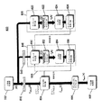
図3は1つまたはそれ以上の追加の基準信号を発生し、利用可能な追加の基準の数およびそれら基準の電力に基づいてルックアップテーブルから最適なステップサイズ
ステップサイズ発生器328はCPICH出力計算器330、HSSCCHチャネル出力計算器332、チャネルイネーブル/ステップサイズ選択器334、および基準計算器336を有する。CPICH出力計算器330は等化信号
HSSCCH出力計算器332は各チャネルkについて逆スクランブルおよび逆拡散されたシンボルrk(n)を受信し、1つのTTIの最大について、各HSSCCHチャネルkのシンボル電力を計算する。この実施形態では、シンボル1つ当たり128チップが存在する場合、その電力は式(10)および(11)に示すように計算される:
Hssch_Power_Nrk(n)=N (12)
可能性のある1実施形態では、Nが1に等しくなるように電力計算には1つのシンボルだけが使用される。他の実施形態では、式(11)の電力を発生するのに用いられるシンボルの数Nは1より大きくなり得る。例えば、式(11)の電力は、長さが7680チップであり、シンボル1つ当たり128チップを有する伝送時間インターバル(TTI)について計算され得る。この場合、数NはNが60に等しくなるまで(すなわち、7680/128=60)、128チップ毎に1だけ増分されるであろう。次のTTIの開始時に、Nは0にリセットされる。
The
Hssch_Power_Nr k (n) = N (12)
In one possible embodiment, only one symbol is used in the power calculation so that N is equal to one. In other embodiments, the number N of symbols used to generate the power of equation (11) may be greater than one. For example, the power of equation (11) may be calculated for a transmission time interval (TTI) that is 7680 chips in length and has 128 chips per symbol. In this case, the number N will be incremented by 1 every 128 chips until N equals 60 (ie, 7680/128 = 60). At the start of the next TTI, N is reset to zero.
チャネルイネーブル/ステップサイズ選択器334は、各HSSCCHチャネルkについてのCPICH出力計算器330およびHSSCCH出力計算器332からの計算値を受け取る。次いで、これらの計算値を用いてどのチャネルがトレーニングおよびトラッキングに使用可能であるかが検出される。使用可能なチャネル数および各チャネルの電力に基づき、チャネルイネーブル/ステップサイズ選択器334が、ルックアップテーブルから最適なステップサイズを検索するのに用いられる指数を識別する。このプロセスは擬似コードの逐次段階を通して実行され得る。
Channel enable /
図4(a)および(b)は図3のチャネルイネーブル/ステップサイズ選択器334の機能を実施する擬似コード400の1実施を示す。図5は図4(a)および(b)の擬似コード400についてのパラメータの表を示す。擬似コード400のライン1では、
chip_countが所定周波数HSSCCH_SELECTOR_FREQUENCYと比較される。考えられる1つの実施では、HSSCCH_SELECTOR_FREQUENCYが128チップになるように選択される。擬似コード400は128チップ毎に、図4(a)のライン3から9に示したような先の反復の間で、4つのHSSCCHチャネルについて計算された値をリセットする。
4 (a) and 4 (b) show one implementation of
The chip_count is compared with a predetermined frequency HSSCCH_SELECTOR_FREQENCY. In one possible implementation, HSSCCH_SELECTOR_FREQENCY is selected to be 128 chips.
ライン11では、擬似コード400はより高い層から受け取られた情報を用いて、どのHSSCCHチャネルが存在するかを決定する。存在し得る各チャネルについて、チャネルイネーブル/ステップサイズ選択器334がHSSCCH_Channel_SW_Enabled[k]信号を受信する。次いで、擬似コード400が4つのHSSCCHチャネルのどれが追加の基準信号として用いるのに十分な電力を有するかを決定する(ライン10から24)。次いで、十分な電力を有するチャネルがイネーブルになる。特に、擬似コード400のラインでは13、各HSSCCHチャネルの平均電力(Hsscch_Power_Est[k])は、計算された相当するHSSCCH電力(Hsscch_Power_Sum[k])を電力計算に用いられたシンボルの総数(Hsscch_Power_Nrk(n))で割ることによって計算される。次いで、各平均電力を用いて、ライン14に示したような、各チャネルkについての電力比(Calculated_pwr_ratio[k])が計算される。
In
各チャネルkについての電力比は、最大電力比(HSSCCH_MAX_PWR_FOR_TRAINING)および最小電力比(HSSCCH_MIN_PWR_FOR_TRAINING)についての所定の閾値と比較される(ライン15から20)。あるチャネルkの電力比が最大閾値より大きい場合、擬似コード400がそのチャネルの電力比を最大閾値と等しく設定する。次いで、電力比が最小閾値より大きいが、最大閾値以下である各チャネルkに関し、擬似コード400がその電力比の平方根を計算し(Calculated_SQPWRS[k])、イネーブル信号を真に設定する(HSSCCH_Channel_Enabled[k])(それぞれライン22および23)。電力比が最小電力比閾値より低いチャネルkはイネーブルにされない(すなわち、追加の基準信号を発生させるのに用いられない)。
The power ratio for each channel k is compared to a predetermined threshold for the maximum power ratio (HSSCCH_MAX_PWR_FOR_TRAING) and the minimum power ratio (HSSCCH_MIN_PWR_FOR_TRAING) (
本発明の代替実施形態では、擬似コード400は上記電力比以外の電力値を発生し得ることに留意されたい。また、擬似コード400はこの他の電力値が上記最小閾値以外の電力閾値条件を満たすかどうかも決定し得る。例えば、擬似コード400はCPICH電力がHSSCCH電力によって割られる電力値を計算してもよい(すなわち、Cpich_Power_estimate/Hsscch_Power_Est[k])。この例では、HSSCCHチャネルはHSSCCHチャネルの電力値が最大閾値未満のときに電力閾値条件を満たす。他の実施が本発明の範囲内で可能である。
Note that in alternative embodiments of the present invention,
次に、擬似コード400は、各チャネルを2ビットの2進数に関連付けることによって各チャネルkを:高電力、中電力、低電力、または超低電力チャネルとして指定する(TCBin[k]=0、1、2、3)(ライン25から34)。高電力チャネルは所定の最大電力比(HSSCCH_BIN_LIMIT_MAX)より大きい電力比を有し、3に等しい2ビットの2進数が割り当てられる(ライン28から29)。中電力チャネルは所定の中電力比(HSSCCH_BIN_LIMIT_MID)よりも大きく、最大電力比以下の電力比を有する。各中電力チャネルには2に等しい2ビットの2進数(ライン30から31)が割り当てられる。低電力チャネルは所定の最小電力比(HSSCCH_BIN_LIMIT_MIN)より大きく、中電力比以下の電力比を有する。各低電力チャネルには1に等しい2ビットの2進数が割り当てられる(ライン32から33)。超低電力チャネルは最小電力比以下の電力比を有し、0に等しい2ビットの2進数が割り当てられる(ライン34)。
各チャネルkに2進数が割り当てられた後、擬似コード400は最大から最小までの2ビットの2進数をアレンジすることによって最高電力からのチャネルを最低電力にソートし、その結果8ビットの2進数が得られる(図4(b)のライン37)。次いで、この8ビット2進数が、3ビットのルックアップテーブルインデックス番号に相当する4桁の10進数に再計算される(DeltaLUTindex=0,...,7)(ライン41から51)。1例として、3つの低電力チャネルおよび1つの超低電力チャネルを有する伝送は、ルックアップテーブルのインデックス番号3に相当する10進数1110のを生成する(ライン46)。別の例として、1つの高電力チャネル、2つの中電力チャネルおよび1つの低電力チャネルを有する伝送は、ルックアップテーブルのインデックス番号7に相当する10進数3221を生じるであろう(ライン51)。この例およびある種の他の場合には、最後の2または3桁はルックアップテーブルインデックス番号を決定するのに関連しないかもしれないことに留意されたい。
After each channel k is assigned a binary number, the
インデックス番号が決定されると、ステップサイズがルックアップテーブルから選択され得る。テーブルに含まれたステップサイズはハードウェア設計者によって事前に定められてもよく、アプリケーション間で変動し得る。次いで、選択されたステップサイズは図3の係数更新器312に伝送され、そこで、係数計算を実行するのに用いられる。また、チャネルイネーブル信号および各チャネルkについての電力比の平方根が基準計算器336に伝送される。
Once the index number is determined, the step size can be selected from a lookup table. The step sizes included in the table may be predetermined by the hardware designer and may vary between applications. The selected step size is then transmitted to the
図6は図3の受信機300の基準計算器336の1実施形態を示す。基準計算器336は「And」ゲート602およびサムブロック604を有する。各「And」ゲート602はチップシーケンス発生器326からのHSSCCHチャネルまたは受信機によって知られたCPICHチャネルのいずれかを受信する。更に、各「And」ゲートは受信されたチャネル(例えば、HSSCCHチャネルkについての図4のHSSCCH_Channel_Enabled[k])に相当するチャネルイネーブル信号を受信する。CPICHチャネルは常にイネーブルであることに留意されたい。イネーブルなHSSCCHおよびCPICHチャネルが組み合わされる前に、それらを以下の式(13)および(14)に示すようにスケールすることができる。
サムブロック604はスケールされたイネーブルなチャネルを共に加算して1つの合わされた基準信号を作る。合わされた基準信号は乗算器606に伝送され、基準信号はそこで係数2によって乗算される。次いで、乗算器606は合わされた基準信号を図3のエラー計算器314に伝送する。
A
結論
追加の基準信号を発生するのに上記以外のチャネルが用いられる本発明の種々の実施形態が想定され得る。そういったチャネルは3GPP伝送に用いられる他のチャネルまたは3GPP以外の用途に用いられるチャネルであり得る。
CONCLUSION Various embodiments of the invention can be envisaged where channels other than those described above are used to generate additional reference signals. Such a channel may be another channel used for 3GPP transmission or a channel used for applications other than 3GPP.
また、上記以外のチャネルが基準発生器218によって処理されずに追加の基準として用いられてもよい。そういったチャネルには、受信機によって先験的に知られているビットパターンを有するチャネルおよびパイロットチャネルとして以外の目的で使用されるチャネルを含む。例えば、3GPP受信機では、各スロットの最初の10%の間に伝送される同期(SCH)チャネルは、受信機によって知られたビットパターンを有する。このチャネルは、式(4)の知られた基準x(i)がパイロットz(i)およびSCHチャネルの知られた値を含むように、パイロットチャネルに加えて用いられ得る。これらの追加の基準チャネルは、基準発生器218などの基準発生器の存在および使用と無関係に使用され得る。
Also, channels other than those described above may be used as additional criteria without being processed by the
チップレートNLMS等化器以外の等化器が主等化器、補助等化器、または主等化器および補助等化器両方の代わりとして用いられる本発明の代替実施形態が想定され得る。このような他の等化器には、限定するものではないが、LMS等化器および帰納的最小2乗式等化器が挙げられる。 Alternative embodiments of the present invention may be envisaged where an equalizer other than a chip rate NLMS equalizer is used in place of the main equalizer, the auxiliary equalizer, or both the main equalizer and the auxiliary equalizer. Such other equalizers include, but are not limited to, LMS equalizers and recursive least squares equalizers.
本発明の更なる実施形態は、2つまたはそれ以上の受信機を有する装置において実施され得る。2つまたはそれ以上の受信機は、1つまたはそれ以上の受信機がデータ信号から追加の基準信号を発生させることによって補助受信機として機能するように、かつ他の1つまたはそれ以上の受信機が追加の基準信号を用いて受信信号を等化することによって主受信機として機能するように、適合され得る。例えば、R99要件を満たす受信機を有する装置、例えばレイク受信機、およびリリース6またはリリース7信号を受信する高度な受信機がこの発明のために用いられてもよい。
Further embodiments of the present invention may be implemented in an apparatus having two or more receivers. Two or more receivers may function as an auxiliary receiver by one or more receivers generating an additional reference signal from the data signal and one or more other receptions The machine can be adapted to function as a main receiver by equalizing the received signal with an additional reference signal. For example, devices having receivers that meet the R99 requirements, such as rake receivers, and advanced receivers that receive
図7はtransmit−diverse信号を受信するかまたは追加の基準信号を発生させるのに用いることのできる2つの受信機を有する、本発明の1実施形態の装置700の単純化されたブロック図を示す。装置700はダイバーシティ受信モードと基準信号発生モードとの間で装置を切り換えるダイバーシティ選択器740を有する。基準信号発生モードの間、ダイバーシティ選択器は補助受信機の下流側処理部(すなわち、シンボル推定器742およびLLRデマッパー744)を無効にし、装置700は受信機300の機能に類似する機能を実行する(すなわち、基準信号およびステップサイズを発生し、この基準信号およびステップサイズを用いて受信信号を等化する)。ダイバーシティモードの間、ダイバーシティ選択器はCPICH出力計算器730、HSSCCH出力計算器732、チャネルイネーブル/ステップサイズ選択器734、基準計算器736、シンボル決定ブロック724、およびチップシーケンス発生器726を無効にする。このモードでは、装置700は2つのtransmit−diverse信号を受信し、2つの受信機を用いてこの2つの信号を別々に処理する。
FIG. 7 shows a simplified block diagram of an
本発明の更に別の実施形態によれば、補助等化器は主係数更新器によって計算された係数w(i)を使用することもできる。この実施そういった1つの実施形態が図3に示唆されている。図3において受信機300は補助等化器320が係数更新器312から係数wmain(i)を受け取るのを可能にする接続ライン338を有する。この機能は任意のものであり、使用されるときには、補助等化器320はその自身の係数w(i)を計算するために別個の係数更新器を使用しなくてもよい。したがって、電力は補助等化器320の係数更新器を動作させないことによって温存され得る。幾つかの実施形態によれば、補助等化器320は係数更新器を有さなくてもよく、したがって、係数更新器312から受信された係数wmain(i)のみに依存するであろう。他の実施形態によれば、補助等化器320は係数更新器を有してもよく、ある場合には等化器320その自身の係数w(i)を発生することができる、別の場合には、等化器320係数更新器312にから受信された係数wmain(i)に依存することができる。例えば、補助等化器320はその自身の係数w(i)を発生してトレーニングオペレーションを改善してもよい。次いで、トラッキングオペレーションの間は、補助等化器320は電力が温存されるように、係数更新器312からの係数wmain(i)に依存してもよい。
According to yet another embodiment of the invention, the auxiliary equalizer can also use the coefficient w (i) calculated by the main coefficient updater. One such embodiment of this implementation is suggested in FIG. In FIG. 3, the
図8は2つまたはそれ以上の基準発生器を有する、本発明の1実施形態の受信機800の単純化されたブロック図を示す。装置800は上流側処理部802、遅延バッファ816、主NLMS等化器804、デスクランブラ/デスプレッダ806、下流側処理部808を有する。これらは図2の受信機200の相当する要素のオペレーションに類似したオペレーションを実行する。装置800はまたパイプライン型に接続された基準発生器818および848を有する。基準発生器818は基準発生器218のオペレーションと類似するオペレーションを実行して1つまたはそれ以上の基準信号の第1のセットを発生させる。基準発生器848は、遅延バッファ846からの受信信号y(i)の遅延されたバージョンを受信し、1つまたはそれ以上の基準信号の第1のセットおよび考えられる1つまたはそれ以上のパイロット信号を用いて1つまたはそれ以上の基準信号の第2のセットを発生する。次いで、1つまたはそれ以上の基準信号の第2のセットが主等化器804によって用いられて、遅延された受信信号ydelayed(i)を等化し得る。3つ以上の基準発生器を用いる追加の実施形態が想定され得る。この場合、第1の基準発生器を除き、各基準発生器が前の基準発生器から出力された1つまたはそれ以上の基準信号を用いて受信信号を遅延されたバージョンを等化するように、各基準発生器は前の基準発生器とパイプライン式に接続されよう。
FIG. 8 shows a simplified block diagram of a
1つまたはそれ以上の基準信号のセットを反復的に発生する本発明の更に別の実施形態が想定され得る。そういった1つの実施形態が図8に示唆されており、基準発生器848はチップシーケンス発生器856から等化器850まで延びる点線の接続ライン862を示している。1つまたはそれ以上の基準信号のセットを発生後、基準発生器848は1つまたはそれ以上の基準信号のセットおよび可能性のある1つまたはそれ以上のパイロットチャネルを用いて1つまたはそれ以上の基準信号の次のセットを発生することができる。この反復的プロセスは1つまたはそれ以上の基準信号の最終セットを主NLMS等化器804に適用する前に、任意の所望の回数繰り返されてもよい。
Still another embodiment of the present invention can be envisaged that iteratively generates one or more sets of reference signals. One such embodiment is suggested in FIG. 8, where the
パイロット電力を維持し、1つまたはそれ以上の基準信号の追加のセットを反復的に発生するか、または追加の基準発生器を使用することにより、元の伝送信号を近似する際の1つまたはそれ以上の基準信号の最終セットの精度が増大され得る。他方、このパイロット電力は1つまたはそれ以上の基準信号の追加のセットの発生を用いて低減することができ、1つまたはそれ以上の基準信号の最終セットの精度が維持され得る。他の実施はパイロットチャネルの電力および/または数を部分的に低減することによって、パイロット電力の低減および1つまたはそれ以上の基準信号の最終セットの精度の増大の両方を達成することができる。 One or more in approximating the original transmission signal by maintaining pilot power and generating an additional set of one or more reference signals repeatedly or by using an additional reference generator The accuracy of the final set of further reference signals can be increased. On the other hand, this pilot power can be reduced using the generation of an additional set of one or more reference signals, and the accuracy of the final set of one or more reference signals can be maintained. Other implementations can achieve both a reduction in pilot power and an increase in the accuracy of the final set of one or more reference signals by partially reducing the power and / or number of pilot channels.
図8は2つの基準発生器818および848を有するある実施形態を示す。ここでは、基準発生器848は1つまたはそれ以上の基準信号のセットを反復的に発生することができるが、本発明はこれに限定されるものではない。1つの基準発生器またはパイプライン化された複数の基準発生器を使用する種々の実施形態が想定され得る。このうち少なくとも1つの基準発生器は1つまたはそれ以上の基準信号のセットの反復的発生を支援し得る。そういった実施形態の設計は、パイプライン化された基準発生器、反復的発生、またはこの両方を用いることのトレードオフを考慮し得る。特に、1つまたはそれ以上の基準信号のセットを反復的に発生するのに、ハードウェアは少なくて済み、パイプライン化された基準発生器よりも消費する電力は少ない。他方、次の基準発生器が受信信号の特定のセットを処理する間に、前の基準発生器が受信信号の次のセットを処理するのに用いられ得るので、パイプライン化された基準発生器の待ち時間は、反復的処理よりも短くなり得る。種々の実施形態は上記2つのアプローチを組み合せることによってこれらのトレードオフのバランスを取り得る。
FIG. 8 shows an embodiment having two
本明細書で用いられる場合、用語「パイロット」とは、受信機によって先験的に知られているビットパターンを有する任意の信号を指す。したがって、用語「パイロット」は、トレーニング以外には用途のない従来のパイロットチャネルだけでなく第3世代パートナーシッププロジェクト(3GPP)型の受信機に用いられる同期チャネル(SCH)などの他の用途がある知られたチャネルも含む。したがって、図2の基準信号z(i)は、1つまたはそれ以上の他のパイロットチャネルに加えて、あるいはそれに代わって、パイロット(例えば、SCH)して以外に受信機機能のために従来から用いられるチャネルに基づくものであり得る。 As used herein, the term “pilot” refers to any signal having a bit pattern that is known a priori by the receiver. Thus, the term “pilot” is known not only for conventional pilot channels that have no use other than training, but also for other uses such as synchronization channels (SCH) used in third generation partnership project (3GPP) type receivers. Included channels. Thus, the reference signal z (i) of FIG. 2 is conventionally used for receiver functions other than in addition to or in place of one or more other pilot channels (eg, SCH). It can be based on the channel used.
本明細書において「1実施形態」または「ある実施形態」に言及することは、その実施形態に関連して記載された特定の特徴、構造または特性を本発明の少なくとも1つの実施形態に含むことができることを意味する。本明細書の様々な箇所で句「1実施形態では」が登場することは、必ずしももすべて、同じ実施形態を指すものでもないし、別個または代替の実施形態は必ずしも他の実施形態を相互に排除するものでもない。同じことが用語「実施」に当てはまる。 References herein to “one embodiment” or “an embodiment” include in the at least one embodiment of the invention the particular feature, structure, or characteristic described in connection with that embodiment. Means you can. The appearances of the phrase “in one embodiment” in various places in the specification do not necessarily all refer to the same embodiment, and separate or alternative embodiments do not necessarily exclude other embodiments from one another. It's not something to do. The same applies to the term “implementation”.
本発明は、単一の集積回路(ASICまたはFPGAなど)、マルチチップモジュール、単一のカード、またはマルチカード回路パックとしての可能な実施を含む、回路ベースのプロセスとして実施されてよい。当業者には明白であるように、回路要素の種々の機能はソフトウェアプログラムにおける処理ブロックとして実施されてもよい。そういったソフトウェアは、例えば、デジタル信号プロセッサ、マイクロコントローラ、または汎用コンピュータに使用され得る。 The present invention may be implemented as a circuit-based process including possible implementation as a single integrated circuit (such as an ASIC or FPGA), a multi-chip module, a single card, or a multi-card circuit pack. As will be apparent to those skilled in the art, the various functions of the circuit elements may be implemented as processing blocks in a software program. Such software can be used, for example, in digital signal processors, microcontrollers, or general purpose computers.
本発明はそれら方法を実践するための方法および装置の形態で具現化することができる。本発明はまた、有形の媒体、例えば、磁気記録媒体、光学記録媒体、固体メモリ、フロッピー(登録商標)ディスク、CD−ROM、ハードドライブ、または他の任意の機械読取可能記憶媒体において具現化されるプログラムコードの形態で具現化することも可能である。ここでは、プログラムコードがコンピュータなどの機械にロードされ、それによって実行されるとき、機械は本発明を実践する装置となる。本発明はまた、例えば、記憶媒体に格納されるか、機械にロードされるおよび/または機械によって実行されるか、あるいは電線または電気ケーブル、光ファイバ、あるいは電磁放射などの幾つかの伝送媒体またはキャリアにより伝送される、プログラムコードの形態で具現化することもでき、ここでは、プログラムコードがコンピュータなどの機械にロードされ、それによって実行されるとき、機械は本発明を実践する装置となる。汎用プロセッサで実施されるとき、このプログラムコードセグメントはプロセッサと結び付いて特定の論理回路と同様に動作する固有のデバイスを提供する。本発明はまた、本発明の方法および/または装置を用いて発生される、電気的または光学的にある媒体によって伝送される信号値のビットストリームまたは他の配列、磁気記録媒体において格納された磁界の変化、等の形態で具現化することも可能である。 The present invention can be embodied in the form of methods and apparatuses for practicing those methods. The present invention is also embodied in a tangible medium, such as a magnetic recording medium, optical recording medium, solid state memory, floppy disk, CD-ROM, hard drive, or any other machine-readable storage medium. It can also be embodied in the form of program code. Here, when the program code is loaded into and executed by a machine such as a computer, the machine becomes a device for practicing the present invention. The invention can also be stored in a storage medium, loaded into a machine and / or performed by a machine, or some transmission medium such as a wire or electrical cable, optical fiber, or electromagnetic radiation, or It can also be embodied in the form of program code transmitted by a carrier, where the machine becomes an apparatus for practicing the invention when the program code is loaded into and executed by a machine such as a computer. When implemented on a general-purpose processor, the program code segments combine with the processor to provide a unique device that operates analogously to specific logic circuits. The present invention also provides a bitstream or other arrangement of signal values transmitted by an electrical or optical medium generated using the method and / or apparatus of the present invention, a magnetic field stored in a magnetic recording medium. It is also possible to embody in a form such as a change.
明示しない限り、各数値および範囲は、単語「about」または「approximately」がその値または範囲の値の頭に付いているかのように、概算的なものであると解釈されるべきである。 Unless explicitly stated, each numerical value and range should be interpreted as being approximate, as if the word “about” or “approximated” precedes the value of the value or range.
本発明の性質を説明するために記載し、例示したパーツの詳細、材料、および配置の様々な変更が、添付の特許請求の範囲に明示されたような本発明の範囲を逸脱することなく
当業者によってなされてよいことを更に理解されたい。
Various changes in the details, materials, and arrangement of parts described and illustrated to illustrate the nature of the invention may be made without departing from the scope of the invention as set forth in the appended claims. It should be further understood that this may be done by a vendor.
図面番号および/または図面の参照ラベルを各請求項において用いることは、特許請求の範囲を解釈し易くするために、特許請求される主題の1つまたはそれ以上の可能な実施形態を特定することを意図するものである。こういった使用は必ずしも対応する図に示した実施形態に特許請求の範囲を限定するものと解釈されるべきではない。 The use of drawing numbers and / or reference labels in the drawings in each claim identifies one or more possible embodiments of the claimed subject matter to facilitate interpreting the claims. Is intended. Such use is not necessarily to be construed as limiting the scope of the claims to the embodiments shown in the corresponding figures.
本明細書に記載した例示の方法のステップは必ずしも記載の順序で実行される必要はなく、そのような方法のステップの順序は単なる例示であることを理解されたい。同様に、追加のステップがそういった方法に含まれてもよいし、本発明の種々の実施形態と一致する方法において、ある種のステップが省かれてもよいし、組み合わされてもよい。 It should be understood that the steps of the exemplary methods described herein are not necessarily performed in the order described, and the order of the steps of such methods is merely exemplary. Similarly, additional steps may be included in such methods, and certain steps may be omitted or combined in methods consistent with various embodiments of the invention.
添付の特許請求の範囲中の要素は、ある場合には、対応するラベリングを用いて特定の順序で列挙されるが、特許請求の範囲の記述がそれらの要素の一部または全部実施するための特定の順序を暗示しない限り、それらの要素がその特定の順序で実施されることに限定されることを必ずしも意図するものではない。 Elements in the appended claims are, in some cases, listed in a particular order using corresponding labeling, but the claims are intended to implement some or all of those elements. Unless implied by a particular order, it is not necessarily intended that the elements be limited to being performed in that particular order.
Claims (29)
(a)受信信号の少なくとも1つのパイロットチャネルに基づいて1つまたはそれ以上の受信信号の第1のセットを等化して、1つまたはそれ以上の等化信号の第1のセットを発生するステップ;
(b)1つまたはそれ以上の等化信号の前記第1のセットを処理して、前記受信信号の1つまたはそれ以上の非パイロットチャネルの第1のセットに相当する1つまたはそれ以上のデコードデータストリームの第1のセットを発生するステップ;
(c)1つまたはそれ以上のデコードデータストリームの前記第1のセットから1つまたはそれ以上の基準信号を発生するステップ;および
(d)(1)前記少なくとも1つのパイロットチャネルおよび(2)前記1つまたはそれ以上の基準信号の両方に基づいて1つまたはそれ以上の受信信号の第2のセットを等化して、1つまたはそれ以上の等化信号の第2のセットを発生するステップ、を含む、方法。 A method for equalizing a received signal,
(A) equalizing a first set of one or more received signals based on at least one pilot channel of the received signal to generate a first set of one or more equalized signals; ;
(B) processing the first set of one or more equalized signals to correspond to one or more first sets of one or more non-pilot channels of the received signal; Generating a first set of decoded data streams;
(C) generating one or more reference signals from the first set of one or more decoded data streams; and (d) (1) the at least one pilot channel and (2) the Equalizing a second set of one or more received signals based on both one or more reference signals to generate a second set of one or more equalized signals; Including a method.
(1)1つまたはそれ以上の等化信号の前記第1のセットを前記少なくとも1つのパイロットチャネルと比較することによってエラー信号を計算する処理;および
(2)前記エラー信号に基づいてフィルタ係数の前記第1のセットを更新する処理により適応的に発生される、請求項1に記載の方法。 Step (a) includes filtering the first set of one or more received signals based on the first set of filter coefficients, wherein the first set of filter coefficients comprises:
(1) a process of calculating an error signal by comparing the first set of one or more equalized signals with the at least one pilot channel; and (2) a filter coefficient based on the error signal; The method of claim 1, wherein the method is adaptively generated by the process of updating the first set.
(1)1つまたはそれ以上の等化信号の前記第2のセットを(i)前記少なくとも1つのパイロットチャネルおよび(ii)前記1つまたはそれ以上の基準信号の両方と比較することによってエラー信号を計算する処理;および
(2)前記エラー信号に基づいてフィルタ係数の前記第2のセットを更新する処理により、適応的に発生される、請求項1に記載の方法。 Step (d) comprises filtering the second set of one or more received signals based on the second set of filter coefficients, wherein the second set of filter coefficients comprises:
(1) an error signal by comparing the second set of one or more equalized signals with both (i) the at least one pilot channel and (ii) the one or more reference signals. The method of claim 1, wherein the method is adaptively generated by: (2) updating the second set of filter coefficients based on the error signal.
(1)1つまたはそれ以上のデコードデータストリームの前記第1のセットについて硬決定の第1のセットを発生する処理;および
(2)前記1つまたはそれ以上の基準信号として用いられる硬決定の前記第1のセットを記録する処理を含む、請求項1に記載の方法。 Step (c) is:
(1) processing to generate a first set of hard decisions for the first set of one or more decoded data streams; and (2) hard decisions used as the one or more reference signals. The method of claim 1, comprising processing to record the first set.
(1)前記1つまたはそれ以上の非パイロットチャネルの各々に関連する電力値が電力閾値条件を満たすかどうかを決定する処理;および
(2)基準信号を発生するのに使用するために、関連する電力値が前記電力閾値条件を満たす非パイロットチャネルに相当する各デコードデータストリームをイネーブルにする処理を含む、請求項1に記載の方法。 Step (c) is:
(1) a process for determining whether a power value associated with each of the one or more non-pilot channels satisfies a power threshold condition; and (2) an association for use in generating a reference signal. The method of claim 1, comprising enabling each decoded data stream corresponding to a non-pilot channel whose power value to satisfy the power threshold condition.
(1)(a)前記受信信号の少なくとも1つのパイロットチャネルに基づいて1つまたはそれ以上の受信信号の第1のセットを等化して、1つまたはそれ以上の等化信号の第1のセットを発生するように適合された第1の等化器(例えば220)、(b)1つまたはそれ以上の等化信号の前記第1のセットを処理して、前記受信信号の1つまたはそれ以上の非パイロットチャネルの第1のセットに相当する1つまたはそれ以上のデコードデータストリームの第1のセットを発生するように適合された第1のデコーダ(例えば222)、(c)シンボル決定ブロック(例えば224)、および1つまたはそれ以上のデコードデータストリームの前記第1のセットから1つまたはそれ以上の基準信号を発生するように適合されチップシーケンス発生器(例えば226)を含む、
1つまたはそれ以上の受信信号の前記第1のセットから前記1つまたはそれ以上の基準信号を発生するように適合された第1の基準発生器(例えば218)と、
(2)(i)前記少なくとも1つのパイロットチャネルおよび(ii)前記1つまたはそれ以上の基準信号の両方に基づいて1つまたはそれ以上の受信信号の第2のセットを等化して、1つまたはそれ以上の等化信号の第2のセットを発生するように適合された第2の等化器(例えば204)とを備える、装置。 An apparatus for equalizing a received signal,
(1) (a) a first set of one or more equalized signals by equalizing a first set of one or more received signals based on at least one pilot channel of the received signals; A first equalizer adapted to generate (e.g. 220), (b) processing the first set of one or more equalized signals to produce one or more of the received signals A first decoder adapted to generate a first set of one or more decoded data streams corresponding to the first set of non-pilot channels (eg 222), (c) a symbol determination block Adapted to generate one or more reference signals from the first set of one or more decoded data streams (eg 224), and one or more decoded data streams. Containing vessels (e.g. 226),
A first reference generator (eg, 218) adapted to generate the one or more reference signals from the first set of one or more received signals;
(2) equalizing a second set of one or more received signals based on both (i) the at least one pilot channel and (ii) the one or more reference signals; Or a second equalizer (eg, 204) adapted to generate a second set of equalized signals or more.
前記第1の基準発生器および前記1つまたはそれ以上の追加の基準発生器がパイプライン化された様式で接続され;
各追加の基準発生器が(i)前記受信信号の少なくとも1つのパイロットチャネルおよび(ii)パイプライン化された前の基準発生器によって発生された1つまたはそれ以上の基準信号に基づいて、1つまたはそれ以上の受信信号の前記第1のセットを等化するように適合された、請求項16に記載の装置。 The apparatus further comprises one or more additional reference generators (eg 848);
The first reference generator and the one or more additional reference generators are connected in a pipelined manner;
Each additional reference generator is based on (i) at least one pilot channel of the received signal and (ii) one or more reference signals generated by the pipelined previous reference generator. The apparatus of claim 16, adapted to equalize the first set of one or more received signals.
フィルタ係数の前記第1のセットが、
(1)1つまたはそれ以上の等化信号の前記第1のセットを少なくとも前記1つのパイロットチャネルと比較することによってエラー信号を計算すること;および
(2)前記エラー信号に基づいてフィルタ係数の前記第1のセットを更新すること
によって適応的に発生される、請求項14に記載の装置。 The first equalizer is adapted to filter the first set of one or more received signals based on the first set of filter coefficients;
The first set of filter coefficients is
(1) calculating an error signal by comparing the first set of one or more equalized signals with at least the one pilot channel; and (2) a filter coefficient based on the error signal; The apparatus of claim 14, wherein the apparatus is adaptively generated by updating the first set.
フィルタ係数の前記第2のセットが、
(1)1つまたはそれ以上の等化信号の第2のセットを(i)前記少なくとも1つのパイロットチャネルおよび(ii)前記1つまたはそれ以上の基準信号の両方と比較することによってエラー信号を計算すること;および
(2)前記エラー信号を用いてフィルタ係数の前記第2のセットを更新することによって適応的に発生される、請求項14に記載の装置。 The second equalizer comprises a filter (eg, 210) adapted to filter the second set of one or more received signals based on the second set of filter coefficients;
The second set of filter coefficients is
(1) error signal by comparing a second set of one or more equalized signals with both (i) the at least one pilot channel and (ii) the one or more reference signals. 15. The apparatus of claim 14, wherein the apparatus is adaptively generated by calculating; and (2) updating the second set of filter coefficients with the error signal.
(1)前記1つまたはそれ以上のデコードデータストリームのために硬決定の第1のセットを発生するように適合された、シンボル決定処理部(例えば224)と;
(2)前記1つまたはそれ以上の基準信号として用いられるために硬決定の前記第1のセットを記録するように適合された、チップシーケンス再生成処理部(例えば226)とを備える、請求項14に記載の装置。 The first reference signal generator comprises:
(1) a symbol decision processor (eg, 224) adapted to generate a first set of hard decisions for the one or more decoded data streams;
(2) comprising a chip sequence regeneration processor (eg, 226) adapted to record the first set of hard decisions to be used as the one or more reference signals. 14. The apparatus according to 14.
(1)1つまたはそれ以上の非パイロットチャネルの各々に関連する電力値が電力閾値条件を満たすかどうかを決定するように;かつ
(2)基準信号を発生するのに使用するために、関連する電力値が前記電力閾値条件を満たす非パイロットチャネルに相当する各デコードデータストリームをイネーブルにするように、適合された、請求項14に記載の装置。 The first reference signal generator is:
(1) to determine whether the power value associated with each of the one or more non-pilot channels satisfies a power threshold condition; and (2) related to use to generate a reference signal 15. The apparatus of claim 14, adapted to enable each decoded data stream corresponding to a non-pilot channel whose power value to satisfy the power threshold condition.
前記第1および第2の等化器がtransmit−diverse信号を別々に処理するように機能するように構成された第2の構成を支援する、請求項14に記載の装置。 A first configuration in which the apparatus is configured to generate the one or more reference signals used by the second equalizer; and the first and second 15. The apparatus of claim 14, wherein the second equalizer supports a second configuration configured to function to separately process a transmit-diverce signal.
フィルタ係数の前記セットが、
(1)前記等化信号を、第1のチャネルがパイロットチャネルとして以外の目的で前記受信機によって用いられる前記受信機によって先験的に知られたビットパターンを有する少なくとも第1のチャネルを含む1つまたはそれ以上の基準チャネルと比較することによってエラー信号を計算する処理;および
(2)前記エラー信号に基づいてフィルタ係数の前記セットを更新する処理によって適応的に発生される、方法。 A method of equalizing a received signal of a receiver by filtering the received signal based on a set of filter coefficients to generate an equalized signal,
The set of filter coefficients is
(1) The equalization signal includes at least a first channel having a bit pattern a priori known by the receiver used by the receiver for purposes other than the first channel as a pilot channel 1 Calculating the error signal by comparing with one or more reference channels; and (2) adaptively generated by the process of updating the set of filter coefficients based on the error signal.
Applications Claiming Priority (2)
| Application Number | Priority Date | Filing Date | Title |
|---|---|---|---|
| US75851406P | 2006-01-12 | 2006-01-12 | |
| PCT/US2007/000622 WO2007126446A2 (en) | 2006-01-12 | 2007-01-10 | Receiver employing non-pilot reference channels for equalizing a received signal |
Publications (2)
| Publication Number | Publication Date |
|---|---|
| JP2009524285A true JP2009524285A (en) | 2009-06-25 |
| JP2009524285A5 JP2009524285A5 (en) | 2010-02-18 |
Family
ID=38655955
Family Applications (1)
| Application Number | Title | Priority Date | Filing Date |
|---|---|---|---|
| JP2008550377A Pending JP2009524285A (en) | 2006-01-12 | 2007-01-10 | Receiver using non-pilot reference channel to equalize received signal |
Country Status (6)
| Country | Link |
|---|---|
| US (2) | US8098723B2 (en) |
| EP (1) | EP1980072A2 (en) |
| JP (1) | JP2009524285A (en) |
| KR (1) | KR101393450B1 (en) |
| AU (1) | AU2007243937B2 (en) |
| WO (1) | WO2007126446A2 (en) |
Cited By (1)
| Publication number | Priority date | Publication date | Assignee | Title |
|---|---|---|---|---|
| JP2017517936A (en) * | 2014-04-24 | 2017-06-29 | 富士通株式会社 | Adaptive equalizer, adaptive equalization method and receiver |
Families Citing this family (11)
| Publication number | Priority date | Publication date | Assignee | Title |
|---|---|---|---|---|
| US7660568B2 (en) * | 2004-09-27 | 2010-02-09 | Alcatel-Lucent Usa Inc. | Method and apparatus for generating a channel estimate using a non-pilot portion of a signal |
| EP1924004B1 (en) * | 2005-09-06 | 2015-04-08 | Fujitsu Ltd. | Equalizer device and method |
| US8098723B2 (en) | 2006-01-12 | 2012-01-17 | Agere Systems Inc. | Receiver employing non-pilot reference channels for equalizing a received signal |
| CN102106171B (en) * | 2009-04-27 | 2014-06-25 | 华为技术有限公司 | Method and device for switching |
| US8315339B2 (en) * | 2009-05-05 | 2012-11-20 | Telefonaktiebolaget Lm Ericsson (Publ) | Channel estimation |
| WO2011123017A1 (en) * | 2010-03-31 | 2011-10-06 | Telefonaktiebolaget L M Ericsson (Publ) | Methods and devices for carrier activation/deactivation in a multi-carrier communication system |
| CN102025392A (en) * | 2010-12-06 | 2011-04-20 | 意法·爱立信半导体(北京)有限公司 | Interference elimination method and device |
| US9078179B2 (en) * | 2012-11-16 | 2015-07-07 | Qualcomm Incorporated | IRAT measurement reporting method in TD-SCDMA |
| US9237044B1 (en) * | 2013-05-17 | 2016-01-12 | Altera Corporation | Methods for joint optimization of link equalization |
| WO2020102824A2 (en) | 2018-11-14 | 2020-05-22 | Skywave Networks Llc | Low-latency channel equalization using a secondary channel |
| CN110784424B (en) * | 2019-11-04 | 2022-03-22 | 中国电子科技集团公司第五十四研究所 | Intelligent combined balancing device for self-adaptive transmission link |
Citations (2)
| Publication number | Priority date | Publication date | Assignee | Title |
|---|---|---|---|---|
| EP1372308A1 (en) * | 2002-06-11 | 2003-12-17 | Texas Instruments Incorporated | Method and apparatus for adaptive channel equalization using decision feedback |
| US20040127164A1 (en) * | 2002-12-20 | 2004-07-01 | Texas Instruments Incorporated | Reconfigurable chip level equalizer architecture |
Family Cites Families (26)
| Publication number | Priority date | Publication date | Assignee | Title |
|---|---|---|---|---|
| US4021738A (en) | 1976-03-01 | 1977-05-03 | Bell Telephone Laboratories, Incorporated | Adaptive equalizer with fast convergence properties |
| DE2945331C2 (en) | 1979-11-09 | 1984-05-30 | Nixdorf Computer Ag, 4790 Paderborn | Device in a signal or data processing system for setting a signal processing circuit |
| FR2554996B1 (en) | 1983-11-14 | 1986-02-28 | Labo Electronique Physique | METHOD AND DEVICE FOR DETERMINING THE OPTIMAL POSITION OF THE REFERENCE COEFFICIENT OF AN ADAPTIVE EQUALIZER |
| EP0511698B1 (en) * | 1991-04-23 | 1998-07-08 | Laboratoires D'electronique Philips S.A.S. | Semi-recursive adaptive equalizer |
| JP2833609B2 (en) | 1991-09-12 | 1998-12-09 | 日本電気株式会社 | Decision feedback type automatic equalizer |
| JP2770839B2 (en) | 1992-02-26 | 1998-07-02 | 日本電気株式会社 | Adaptive receiver |
| JP2746107B2 (en) | 1994-03-31 | 1998-04-28 | 日本電気株式会社 | Feedforward amplifier |
| DE19506324C1 (en) | 1995-02-23 | 1995-10-12 | Siemens Ag | Adaptive balance filter guaranteeing optimal matching to line |
| KR100224837B1 (en) | 1997-02-21 | 1999-10-15 | 윤종용 | Method and circuit for adaptive signal processing in digital vcr |
| JP2000182330A (en) | 1998-12-16 | 2000-06-30 | Matsushita Electric Ind Co Ltd | Information reproducing method and information reproducing device |
| US7269212B1 (en) | 2000-09-05 | 2007-09-11 | Rambus Inc. | Low-latency equalization in multi-level, multi-line communication systems |
| AU2001250925A1 (en) | 2000-03-21 | 2001-10-03 | Telcordia Technologies, Inc. | Combined adaptive spatio-temporal processing and multi-user detection for cdma wireless systems |
| US7072392B2 (en) | 2000-11-13 | 2006-07-04 | Micronas Semiconductors, Inc. | Equalizer for time domain signal processing |
| US7006566B2 (en) * | 2001-04-10 | 2006-02-28 | Koninklijke Philips Electronics N.V. | Two stage equalizer for trellis coded systems |
| US7106792B2 (en) * | 2001-06-04 | 2006-09-12 | Qualcomm, Inc. | Method and apparatus for estimating the signal to interference-plus-noise ratio of a wireless channel |
| EP1421700A4 (en) | 2001-08-10 | 2008-04-23 | Adaptive Networks Inc | Digital equalization process and mechanism |
| US20030219113A1 (en) | 2002-05-21 | 2003-11-27 | Bershad Neil J. | Echo canceller with double-talk and channel impulse response adaptation |
| US7167507B2 (en) | 2002-07-01 | 2007-01-23 | Lucent Technologies Inc. | Equalizer and method for performing equalization in a wireless communications system |
| FR2860669B1 (en) | 2003-10-07 | 2005-12-02 | Inst Francais Du Petrole | METHOD FOR RE-ESTABLISHING DEFORMED DATA FOLLOWING THEIR TRANSMISSION ON A TRANSMISSION CABLE |
| US20050249274A1 (en) | 2004-05-10 | 2005-11-10 | Larosa Christopher P | Linear filter equalizer |
| US7116705B2 (en) * | 2004-11-08 | 2006-10-03 | Interdigital Technology Corporation | Method and apparatus for reducing the processing rate of a chip-level equalization receiver |
| US7684481B2 (en) * | 2005-03-01 | 2010-03-23 | Broadcom Corporation | High speed data packet access minimum mean squared equalization with direct matrix inversion training |
| US7529297B2 (en) * | 2005-03-01 | 2009-05-05 | Broadcom Corporation | Equalizer training method using re-encoded bits and known training sequences |
| JP2007006264A (en) | 2005-06-24 | 2007-01-11 | Toshiba Corp | Diversity receiver |
| US8098723B2 (en) * | 2006-01-12 | 2012-01-17 | Agere Systems Inc. | Receiver employing non-pilot reference channels for equalizing a received signal |
| US20080063041A1 (en) | 2006-09-08 | 2008-03-13 | Noam Galperin | Fast training equalization of a signal |
-
2007
- 2007-01-10 US US12/158,388 patent/US8098723B2/en not_active Expired - Fee Related
- 2007-01-10 AU AU2007243937A patent/AU2007243937B2/en not_active Ceased
- 2007-01-10 KR KR1020087019804A patent/KR101393450B1/en not_active IP Right Cessation
- 2007-01-10 JP JP2008550377A patent/JP2009524285A/en active Pending
- 2007-01-10 WO PCT/US2007/000622 patent/WO2007126446A2/en active Application Filing
- 2007-01-10 EP EP07794310A patent/EP1980072A2/en not_active Withdrawn
-
2011
- 2011-12-06 US US13/311,654 patent/US8462839B2/en not_active Expired - Fee Related
Patent Citations (2)
| Publication number | Priority date | Publication date | Assignee | Title |
|---|---|---|---|---|
| EP1372308A1 (en) * | 2002-06-11 | 2003-12-17 | Texas Instruments Incorporated | Method and apparatus for adaptive channel equalization using decision feedback |
| US20040127164A1 (en) * | 2002-12-20 | 2004-07-01 | Texas Instruments Incorporated | Reconfigurable chip level equalizer architecture |
Cited By (1)
| Publication number | Priority date | Publication date | Assignee | Title |
|---|---|---|---|---|
| JP2017517936A (en) * | 2014-04-24 | 2017-06-29 | 富士通株式会社 | Adaptive equalizer, adaptive equalization method and receiver |
Also Published As
| Publication number | Publication date |
|---|---|
| KR20080087159A (en) | 2008-09-30 |
| AU2007243937A1 (en) | 2007-11-08 |
| EP1980072A2 (en) | 2008-10-15 |
| US8462839B2 (en) | 2013-06-11 |
| WO2007126446A2 (en) | 2007-11-08 |
| US20120076194A1 (en) | 2012-03-29 |
| US8098723B2 (en) | 2012-01-17 |
| WO2007126446A3 (en) | 2008-04-17 |
| AU2007243937B2 (en) | 2011-03-17 |
| KR101393450B1 (en) | 2014-05-13 |
| US20090080506A1 (en) | 2009-03-26 |
Similar Documents
| Publication | Publication Date | Title |
|---|---|---|
| JP2009524285A (en) | Receiver using non-pilot reference channel to equalize received signal | |
| US6975672B2 (en) | Apparatus and methods for intersymbol interference compensation in spread spectrum communications | |
| US6956893B2 (en) | Linear minimum mean square error equalization with interference cancellation for mobile communication forward links utilizing orthogonal codes covered by long pseudorandom spreading codes | |
| US7693210B2 (en) | Hybrid rake/equalizer receiver for spread spectrum systems | |
| JP5346074B2 (en) | Method and apparatus for successive interference cancellation with covariance route processing | |
| US20090296798A1 (en) | Hsdpa co-processor for mobile terminals | |
| US8654913B2 (en) | Equalisation processing | |
| US8126043B2 (en) | Method and apparatus for block-based signal demodulation | |
| US20060034352A1 (en) | Methods and apparatus to facilitate improved code division multiple access receivers | |
| CN1203693C (en) | Adaptive equalization method and adaptive equalizer | |
| TW200931901A (en) | A radio receiver in a wireless communications system | |
| TW200935830A (en) | A radio receiver in a wireless communications system | |
| US8611398B2 (en) | Process for processing MIMO data streams in a 3GPP HSDPA receiver, and receiver for doing the same | |
| WO2014139953A1 (en) | Iterative successive interference cancellation in mu-mimo using interference whitening and channel reestimation | |
| JP2005518152A (en) | Method and system for equalizing signals transmitted over a channel of a communication system | |
| US20080075159A1 (en) | Receiver having multiple stages of equalization with tap coefficient copying | |
| KR100993183B1 (en) | Hybrid rake/equalizer receiver for spread spectrum systems | |
| WO2009029340A1 (en) | System and method for equalizing an incoming signal |
Legal Events
| Date | Code | Title | Description |
|---|---|---|---|
| A521 | Request for written amendment filed |
Free format text: JAPANESE INTERMEDIATE CODE: A523 Effective date: 20091216 |
|
| A621 | Written request for application examination |
Free format text: JAPANESE INTERMEDIATE CODE: A621 Effective date: 20091216 |
|
| A521 | Request for written amendment filed |
Free format text: JAPANESE INTERMEDIATE CODE: A523 Effective date: 20101216 |
|
| A131 | Notification of reasons for refusal |
Free format text: JAPANESE INTERMEDIATE CODE: A131 Effective date: 20120130 |
|
| A521 | Request for written amendment filed |
Free format text: JAPANESE INTERMEDIATE CODE: A523 Effective date: 20120501 |
|
| A02 | Decision of refusal |
Free format text: JAPANESE INTERMEDIATE CODE: A02 Effective date: 20120807 |