JP2009523547A - 3D scan recovery - Google Patents
3D scan recovery Download PDFInfo
- Publication number
- JP2009523547A JP2009523547A JP2008551367A JP2008551367A JP2009523547A JP 2009523547 A JP2009523547 A JP 2009523547A JP 2008551367 A JP2008551367 A JP 2008551367A JP 2008551367 A JP2008551367 A JP 2008551367A JP 2009523547 A JP2009523547 A JP 2009523547A
- Authority
- JP
- Japan
- Prior art keywords
- dimensional
- image
- images
- data
- data set
- Prior art date
- Legal status (The legal status is an assumption and is not a legal conclusion. Google has not performed a legal analysis and makes no representation as to the accuracy of the status listed.)
- Withdrawn
Links
Images


Classifications
-
- G—PHYSICS
- G06—COMPUTING; CALCULATING OR COUNTING
- G06T—IMAGE DATA PROCESSING OR GENERATION, IN GENERAL
- G06T17/00—Three dimensional [3D] modelling, e.g. data description of 3D objects
-
- A—HUMAN NECESSITIES
- A61—MEDICAL OR VETERINARY SCIENCE; HYGIENE
- A61C—DENTISTRY; APPARATUS OR METHODS FOR ORAL OR DENTAL HYGIENE
- A61C9/00—Impression cups, i.e. impression trays; Impression methods
- A61C9/004—Means or methods for taking digitized impressions
- A61C9/0046—Data acquisition means or methods
-
- G—PHYSICS
- G01—MEASURING; TESTING
- G01B—MEASURING LENGTH, THICKNESS OR SIMILAR LINEAR DIMENSIONS; MEASURING ANGLES; MEASURING AREAS; MEASURING IRREGULARITIES OF SURFACES OR CONTOURS
- G01B11/00—Measuring arrangements characterised by the use of optical techniques
- G01B11/24—Measuring arrangements characterised by the use of optical techniques for measuring contours or curvatures
-
- G—PHYSICS
- G06—COMPUTING; CALCULATING OR COUNTING
- G06T—IMAGE DATA PROCESSING OR GENERATION, IN GENERAL
- G06T7/00—Image analysis
- G06T7/30—Determination of transform parameters for the alignment of images, i.e. image registration
-
- A—HUMAN NECESSITIES
- A61—MEDICAL OR VETERINARY SCIENCE; HYGIENE
- A61C—DENTISTRY; APPARATUS OR METHODS FOR ORAL OR DENTAL HYGIENE
- A61C9/00—Impression cups, i.e. impression trays; Impression methods
- A61C9/004—Means or methods for taking digitized impressions
- A61C9/0046—Data acquisition means or methods
- A61C9/0086—Acoustic means or methods
-
- G—PHYSICS
- G06—COMPUTING; CALCULATING OR COUNTING
- G06T—IMAGE DATA PROCESSING OR GENERATION, IN GENERAL
- G06T2200/00—Indexing scheme for image data processing or generation, in general
- G06T2200/04—Indexing scheme for image data processing or generation, in general involving 3D image data
-
- G—PHYSICS
- G06—COMPUTING; CALCULATING OR COUNTING
- G06T—IMAGE DATA PROCESSING OR GENERATION, IN GENERAL
- G06T2200/00—Indexing scheme for image data processing or generation, in general
- G06T2200/24—Indexing scheme for image data processing or generation, in general involving graphical user interfaces [GUIs]
-
- G—PHYSICS
- G06—COMPUTING; CALCULATING OR COUNTING
- G06T—IMAGE DATA PROCESSING OR GENERATION, IN GENERAL
- G06T2207/00—Indexing scheme for image analysis or image enhancement
- G06T2207/10—Image acquisition modality
- G06T2207/10016—Video; Image sequence
-
- G—PHYSICS
- G06—COMPUTING; CALCULATING OR COUNTING
- G06T—IMAGE DATA PROCESSING OR GENERATION, IN GENERAL
- G06T2207/00—Indexing scheme for image analysis or image enhancement
- G06T2207/10—Image acquisition modality
- G06T2207/10028—Range image; Depth image; 3D point clouds
-
- G—PHYSICS
- G06—COMPUTING; CALCULATING OR COUNTING
- G06T—IMAGE DATA PROCESSING OR GENERATION, IN GENERAL
- G06T2207/00—Indexing scheme for image analysis or image enhancement
- G06T2207/30—Subject of image; Context of image processing
- G06T2207/30004—Biomedical image processing
- G06T2207/30036—Dental; Teeth
Abstract
インクリメンタルな一連の合致させた3次元データセットとして3次元画像を取得するスキャニングシステムは、成功したインクリメンタルな合致性をリアルタイムで試行し、かつ以前取得したデータに対する新規取得データの関係に応じてさまざまな視覚的なユーザーキューとプロセス変更を提供することによって向上する。このシステムを用いて、3次元スキャンをエラーなしに完了させるよう支援することが可能である。さらには、本明細書に記載の方法とシステムを有効な形で用いて、遮蔽面又は閉塞面などの複雑な表面の分離したサブセクションにわたって連続的な3次元スキャンを維持させることによって、この表面をスキャンすることが可能である。ある1つの有用な歯科用途では、咬合状態にある2つの歯列弓について、3次元表面のフルスキャンを得ることが可能である。 Scanning systems that acquire 3D images as a series of incrementally matched 3D datasets attempt a successful incremental match in real time and vary depending on the relationship of newly acquired data to previously acquired data. Improve by providing visual user queues and process changes. With this system, it is possible to assist in completing a three-dimensional scan without error. Furthermore, this method and system described herein can be used effectively to maintain this surface by maintaining a continuous three-dimensional scan across separate subsections of a complex surface such as a shielded or occluded surface. Can be scanned. In one useful dental application, it is possible to obtain a full scan of the three-dimensional surface for two dental arches in the occlusal state.
Description
(発明の分野)
本発明は3次元スキャニングに関するものであり、さらに詳細には、データ取得を無効にした後に3次元スキャンを再開させる技法に関するものである。
(Field of Invention)
The present invention relates to three-dimensional scanning, and more particularly to techniques for resuming a three-dimensional scan after invalidating data acquisition.
(関連出願の相互参照)
本出願は、2006年1月20日申請の米国特許出願第11/337,182号の優先権を主張するものである。
(Cross-reference of related applications)
This application claims priority from US patent application Ser. No. 11 / 337,182, filed Jan. 20, 2006.
(関連技術の説明)
対象物から3次元データを取得するためのさまざまな技法が存在する。これらの技法は、構造レーザー照射又はその他の制御刺激(X線、超音波、又は、磁気共鳴など)を用いる技法から、1つ以上のカメラからキャプチャーしたビデオデータに直接作用する技法まで、多岐に渡る。これらの技法を区別及び比較するための数多くの基準を考案できる一方で、ある1つの広義のカテゴリーでは、インクリメンタル(incremental)な3次元データを取得して3次元フルモデルにまとめあげる連続スキャニングを採用している。
(Description of related technology)
There are various techniques for acquiring three-dimensional data from an object. These techniques range from techniques that use structural laser irradiation or other controlled stimuli (such as X-rays, ultrasound, or magnetic resonance) to techniques that act directly on video data captured from one or more cameras. Cross. While a number of criteria can be devised to distinguish and compare these techniques, one broad category employs continuous scanning that takes incremental 3D data and summarizes it into a full 3D model. ing.
この後者のカテゴリーでは、特定の検出技術に関わらず、スキャニングプロセスは、インクリメンタルデータのキャプチャー、3次元データのインクリメンタルな抽出、及び、インクリメンタルデータの共通座標系への登録、という概念上の工程に分けることができる。最後のレジストレーション工程では、インクリメンタルデータをまとめて、スキャン対象物の単一の3次元モデルを作り上げる。典型的な実施態様では、登録から取得を切り離し、登録は、データ取得の完了後、後処理工程で行う。これによって比較的包括的な処理が可能になる一方で、スキャンが終了するまでスキャン全体の精度と完成度を評価できないため、重大なデメリットが生じる。新たなスキャン(場合によってはフルスキャン)を開始させて、問題のある結果を完全に置き換えなければ、インクリメンタルデータ内の回復不能なエラー又はギャップを識別及び修正できない。商業上の用途では、これによって、スキャニングの有効原価を増大させる遅延と不便性が生じると思われる。 In this latter category, regardless of the specific detection technique, the scanning process is divided into conceptual steps: capturing incremental data, incrementally extracting 3D data, and registering incremental data in a common coordinate system. be able to. In the final registration process, the incremental data is combined to create a single three-dimensional model of the scan object. In an exemplary embodiment, acquisition is decoupled from registration, which is performed in a post-processing step after completion of data acquisition. While this allows for relatively comprehensive processing, there is a significant disadvantage because the accuracy and completeness of the entire scan cannot be evaluated until the scan is complete. Unrecoverable errors or gaps in incremental data cannot be identified and corrected without starting a new scan (possibly a full scan) to completely replace the problematic results. In commercial applications, this may cause delays and inconveniences that increase the effective cost of scanning.
ある特定のケースでは、無効になったか又は使用不能なスキャンセグメントのリカバリ(recovery)は、ロボット工学、非依存指示、又は、大域座標系内にスキャニングデバイスを確実に配置することができるその他の技法を用いることによって、対応することが可能である。このアプローチは、さらなる設備費用を課すのに加え、さらにはスキャンの対象物の位置と配向が同じ大域座標系内に保持されている場合に、前回のスキャンを継続させる目的でしか利用できない。 In certain cases, the recovery of invalid or unusable scan segments is robotics, independent instructions, or other techniques that can reliably place the scanning device in the global coordinate system. It is possible to cope with this by using. In addition to imposing additional equipment costs, this approach can only be used for the purpose of continuing the previous scan if the position and orientation of the object to be scanned are held in the same global coordinate system.
インクリメンタルスキャンにおけるエラーからのリカバリを認識及び支援する処理技法に対するニーズが依然として存在する。また、スキャンの進行中に、無効になったスキャニングシーケンスからのリカバリをサポートするリアルタイムフィードバックシステムに対するニーズも依然として存在する。 There remains a need for processing techniques that recognize and assist recovery from errors in incremental scans. There also remains a need for a real-time feedback system that supports recovery from an invalid scanning sequence while a scan is in progress.
インクリメンタルな一連の合致した3次元データセットとして3次元画像を取得するスキャニングシステムは、成功したインクリメンタルな合致性をリアルタイムで試行し、かつ以前取得したデータに対する新規取得データの関係に応じてさまざまな視覚的なユーザーキューとプロセス変更を提供することによって向上する。このシステムを用いて、3次元スキャンをエラーなしに完了させるよう支援してよい。さらには、本明細書に記載の方法とシステムとを有効な形で用いて、遮蔽面又は閉塞面などの複雑な表面の分離したサブセクションにわたって連続的な3次元スキャンを維持させることによって、表面をスキャンしてよい。ある1つの有用な歯科用途では、咬合状態にある2つの歯列弓について、3次元表面のフルスキャンを得てよい。 Scanning systems that acquire 3D images as an incremental series of matched 3D datasets attempt a successful incremental match in real time and vary in visual depending on the relationship of newly acquired data to previously acquired data. Improve by providing dynamic user queues and process changes. This system may be used to assist in completing the 3D scan without error. In addition, the method and system described herein can be used in an effective manner to maintain a continuous three-dimensional scan across separate subsections of complex surfaces such as shielding surfaces or occlusion surfaces. You may scan. In one useful dental application, a full scan of the three-dimensional surface may be obtained for two dental arches in the occlusal state.
ある1つの態様では、本明細書で開示する方法は、対象物から3次元表面データを3次元画像シーケンス(sequence of three-dimensional images)として取得し、3次元画像シーケンスの各画像が、3次元画像シーケンスのうちの少なくとも1つの以前の画像に合致する、工程と、次の3次元画像のための画像セットを取得する工程と、を含むことが可能である。この画像セットを次の3次元画像に変換でき、かつ次の3次元画像を3次元表面データに合致させることができる場合には、3次元表面データと次の3次元画像は、ディスプレイ内で対象物の2次元画像の上に重ねる。さらに、画像セットを次の3次元画像に変換できないか、又は、次の3次元画像を3次元表面データに合致させることができない場合には、リカバーモード(recover mode)を開始させる。リカバーモードは、対象物の最新の2次元画像を対象物の以前の2次元画像の上にディスプレイ内で重ねる工程を含むことが可能である。この2次元画像は、3次元画像シーケンスのうちの1つの画像を取得した位置から見た対象物の画像を表している。これに加えて、最新の2次元画像は、画像セットを取得した位置から見た対象物の画像を表している。リカバーモードはさらに、後続の3次元画像を少なくとも1つ取得し、後続の3次元画像を3次元画像シーケンスの1つ以上に試行的に合致させることを含むことが可能である。 In one aspect, the method disclosed herein acquires 3D surface data from an object as a sequence of three-dimensional images, and each image of the 3D image sequence is 3D. The method may include matching a previous image of at least one of the image sequences and obtaining an image set for the next three-dimensional image. If this image set can be converted to the next 3D image and the next 3D image can be matched to the 3D surface data, the 3D surface data and the next 3D image are the target in the display. Overlay on a two-dimensional image of an object. Further, if the image set cannot be converted into the next three-dimensional image or the next three-dimensional image cannot be matched with the three-dimensional surface data, a recover mode is started. The recover mode can include overlaying the latest two-dimensional image of the object on the previous two-dimensional image of the object in the display. This two-dimensional image represents an image of the object viewed from the position where one image of the three-dimensional image sequence is acquired. In addition, the latest two-dimensional image represents the image of the object viewed from the position where the image set is acquired. The recover mode may further include acquiring at least one subsequent 3D image and trial matching the subsequent 3D image with one or more of the 3D image sequences.
この方法にはさらに、次の3次元画像に変換でき、かつ次の3次元画像を3次元表面データに合致させることができる場合に、次の3次元画像を3次元表面データに追加することを含むことが可能である。この方法では、以前の2次元画像と最新の2次元画像にビデオフレームを含むことが可能である。この方法にはさらに、ユーザー入力に応じて手動でリカバーモードを開始させることを含めてもよい。また、この方法にはさらに、無効になった取得の検出に応じてリカバーモードを自動的に開始させることを含めてよい。無効になった取得の検出としては、例えばモーションブラー(motion blur)の検出を挙げてよい。無効になった取得の検出としては、3次元データの不十分なリカバリの検出も挙げてよい。この方法では、リカバーモードに、リカバリを試みる際に、対象物の部分を強調表示する工程を含むことが可能である。また、強調表示する部分は、3次元画像シーケンスうちの以前の画像を複数含むことが可能である。リカバーモードは、少なくとも1つの後続の3次元画像をリカバーモード中に取得した1つ以上の追加画像に試行的に合致させる工程を含めてよく、試行的に合致させるには、試行的に合致させる適合性に基づき3次元画像シーケンスから基準画像を選択することを含むことが可能である。試行的に合致させる適合性は、以前の3次元画像内の画像データのエントロピーを基準にしてよい。また、試行的に合致における適合性は、以前の3次元画像内の3次元データの量を基準にしてもよい。これに加えて、又は、これに代えて、試行的な合致(test fitting)における適合性は、イメージングデバイスのレンジ及び視野内における3次元データの配置を基準にしてもよい。試行的な合致のための適合性の判断は、少なくとも1つの後続の3次元画像の、3次元画像シーケンスのうちの1つ以上の画像に対する時間的近接性を基準にしてもよい。試行的な合致のための適合性の判断は、少なくとも1つの後続の3次元画像の、3次元画像シーケンスのうちの1つ以上に対する空間的近接性を基準にしてもよい。リカバーモードには、3次元画像シーケンスのうちの1つ以上の画像を手動で選択する工程を含めてよい。リカバーモードは、3次元画像シーケンスのうちの最初又は最後の画像から基準画像を選択することを含むことが可能である。 The method further includes adding the next 3D image to the 3D surface data if it can be converted to the next 3D image and the next 3D image can be matched to the 3D surface data. It is possible to include. In this way, it is possible to include video frames in the previous 2D image and the latest 2D image. The method may further include manually initiating the recovery mode in response to user input. The method may further include automatically initiating a recovery mode in response to detection of an invalidated acquisition. For example, detection of acquisition that has become invalid may include detection of motion blur. Detection of acquisition that has become invalid may include detection of insufficient recovery of three-dimensional data. In this method, the recovery mode can include a step of highlighting a portion of the object when attempting recovery. Further, the highlighted portion can include a plurality of previous images in the three-dimensional image sequence. The recover mode may include a trial match of at least one subsequent three-dimensional image to one or more additional images acquired during the recover mode, where the trial match is a trial match. It may include selecting a reference image from the three-dimensional image sequence based on suitability. The suitability for trial matching may be based on the entropy of the image data in the previous three-dimensional image. Further, the suitability in trial matching may be based on the amount of three-dimensional data in the previous three-dimensional image. In addition or alternatively, the fit in the test fitting may be based on the range of the imaging device and the placement of the three-dimensional data within the field of view. The determination of suitability for trial matching may be based on temporal proximity of at least one subsequent three-dimensional image to one or more images of the three-dimensional image sequence. The determination of suitability for trial matching may be based on spatial proximity of at least one subsequent three-dimensional image to one or more of the three-dimensional image sequences. The recover mode may include manually selecting one or more images of the three-dimensional image sequence. The recover mode can include selecting a reference image from the first or last image of the three-dimensional image sequence.
別の態様では、本明細書で開示する方法は、対象物の3次元表面データを提供する工程と、対象物の3次元画像のための画像セットを取得する工程とを含むことが可能である。この方法では、画像セットを3次元表面データに合致させることができない場合に、ランディング(landing)モードを開始させてよく、このランディングモードは、前記対象物の最新の2次元画像をディスプレイ内で前記対象物の以前の2次元画像の上に重ねる工程であって、前記以前の2次元画像が、前記3次元表面データのうちの少なくとも一部を取得した位置から見た前記対象物の画像を表し、前記最新の2次元画像が、画像セットを取得した位置から見た対象物の画像を表す工程と、少なくとも後続の3次元画像を1つ取得する工程と、この少なくとも1つの後続の3次元画像を第2の3次元表面復元物に合致させる工程と、前記少なくとも1つの後続の3次元画像を前記3次元表面データに試行的に合致させる工程とを含むことが可能である。この方法では、画像セットを3次元表面データに合致させることができる場合には、3次元表面データと後続の3次元画像を対象物の2次元画像の上にディスプレイ内で重ね、かつ第2の3次元表面再構成物を3次元表面データに追加する。 In another aspect, the methods disclosed herein can include providing three-dimensional surface data of an object and obtaining an image set for a three-dimensional image of the object. . In this method, if the image set cannot be matched to the 3D surface data, a landing mode may be initiated, which will display the latest 2D image of the object in the display. Overlaying a previous two-dimensional image of an object, the previous two-dimensional image representing an image of the object viewed from a position from which at least a portion of the three-dimensional surface data has been acquired The latest two-dimensional image represents the image of the object viewed from the position from which the image set was acquired, the step of acquiring at least one subsequent three-dimensional image, and the at least one subsequent three-dimensional image Matching a second three-dimensional surface reconstruction with a trial matching of the at least one subsequent three-dimensional image with the three-dimensional surface data. A. In this method, if the image set can be matched to the 3D surface data, the 3D surface data and the subsequent 3D image are superimposed on the 2D image of the object in the display, and the second A 3D surface reconstruction is added to the 3D surface data.
この方法では、以前の2次元画像と最新の2次元画像にビデオフレームを含めてもよい。この方法はさらに、ユーザー入力に応じて手動でランディングモードを開始させることを含むことが可能である。この方法は、ランディングモード内で、ランディングを試みる際に、対象物の部分を強調表示することを含むことが可能である。強調表示する部分は、3次元表面データの一部を含むことが可能である。試行的な合致は、基準画像の試行的な合致のための適合性に基づき、3次元表面データから基準画像を選択することを含むことが可能である。試行的な合致のための適合性は、以前の3次元画像内の画像データのエントロピー、以前の3次元画像内の3次元データの量、イメージングデバイスのレンジ及び視野内における3次元データの配置、及び、画像セットの、3次元表面データの一部に対する空間的近接性のうちのいずれか1つ以上を基準としてよい。この方法はさらに、試行的な合致のために、3次元表面データの部分を手動で選択することを含むことが可能である。試行的な合致のためには、3次元表面データを構築する場合に用いた3次元画像シーケンスから、最初又は最後の画像から、基準画像を選択することを含むことが可能である。以前の2次元画像と最新の2次元画像には、ビデオフレームを含めてよい。この方法は、さらに、ユーザー入力に応じてリカバーモードを手動で開始させることを含むことが可能である。これに加えて、この方法はさらに、試行的な合致のために、3次元表面データから部分を手動で選択することを含むことが可能である。 In this method, video frames may be included in the previous two-dimensional image and the latest two-dimensional image. The method may further include manually initiating a landing mode in response to user input. The method may include highlighting a portion of the object when attempting a landing within the landing mode. The highlighted portion can include a part of the three-dimensional surface data. The trial match can include selecting a reference image from the three-dimensional surface data based on the suitability for the trial match of the reference image. Suitability for trial matching is the entropy of image data in the previous 3D image, the amount of 3D data in the previous 3D image, the range of the imaging device and the placement of the 3D data in the field of view, And any one or more of the spatial proximity of the image set to a portion of the 3D surface data. The method can further include manually selecting portions of the three-dimensional surface data for trial matching. For trial matching, it may include selecting a reference image from the first or last image from the three-dimensional image sequence used in constructing the three-dimensional surface data. The previous two-dimensional image and the latest two-dimensional image may include a video frame. The method may further include manually initiating a recovery mode in response to user input. In addition, the method can further include manually selecting portions from the three-dimensional surface data for trial matching.
別の態様では、本明細書で開示するシステムは、対象物から3次元表面データを3次元画像シーケンスとして取得するスキャニングデバイスを搭載することが可能で、3次元画像シーケンスの各画像が、3次元画像シーケンスの少なくとも1つの以前の画像に合致する。スキャニングデバイスには、1つ以上の追加の3次元画像を取得して、それを3次元表面データに追加する取得モードを搭載してよい。これに加えて、スキャニングデバイスには、1つ以上の追加の3次元画像を3次元画像シーケンスのうちの1つ以上の画像に試行的に合致させて取得モードを回復させるリカバリモードを有し、取得モードとリカバリモードとを区別するための1つ以上の視覚的インジケータを提供するようなディスプレイを適応することが可能である。 In another aspect, the system disclosed herein can be equipped with a scanning device that acquires 3D surface data from an object as a 3D image sequence, wherein each image of the 3D image sequence is 3D. Match at least one previous image in the image sequence. The scanning device may be equipped with an acquisition mode that acquires one or more additional 3D images and adds them to the 3D surface data. In addition to this, the scanning device has a recovery mode in which one or more additional three-dimensional images are trially matched to one or more images of the three-dimensional image sequence to recover the acquisition mode; It is possible to adapt the display to provide one or more visual indicators to distinguish between acquisition mode and recovery mode.
このシステムでは、さらに、ディスプレイが、リカバリモードで対象物を操作する際にオペレーターにガイダンスを提供するようになされることが可能である。 In this system, the display can further be adapted to provide guidance to the operator when operating the object in the recovery mode.
別の態様では、第1の対象物から第1の3次元データセットを取得する第1の取得を行う工程と、第1の対象物に対して一定の配向で第2の対象物を配置する工程と、第1の対象物の表面上の位置から始まり、かつ第2の対象物の少なくとも一部を含む第2の3次元データセットを取得する第2の取得を行う工程とが含まれている方法を本明細書で開示する。この方法では、第1の対象物と第2の対象物はそれぞれ、剛体にしてよい。 In another aspect, performing a first acquisition of acquiring a first three-dimensional data set from the first object, and arranging the second object in a fixed orientation relative to the first object. And performing a second acquisition that acquires a second three-dimensional data set that begins at a position on the surface of the first object and includes at least a portion of the second object. A method is disclosed herein. In this method, each of the first object and the second object may be a rigid body.
この方法では、第1の対象物の表面上の位置には、第1の対象物から3次元データを抽出する際に用いた3次元画像シーケンスのうちの空間的に近接する複数の画像を含めてよい。また、この方法では、第1の対象物の表面上の位置には、第1の対象物から3次元データを抽出する際に用いた3次元画像シーケンスのうちの時間的に近接する複数の画像を含めてよい。これに代えて、この方法では、第1の対象物として第1の歯列弓を含むことが可能である。第2の3次元データセットの少なくとも一部を第1の3次元データセットの少なくとも一部に合致させて、統合的な3次元データセットを提供することが可能である。 In this method, the position on the surface of the first object includes a plurality of spatially close images of the three-dimensional image sequence used when extracting the three-dimensional data from the first object. You can. In this method, a plurality of images that are close in time among the three-dimensional image sequence used when extracting the three-dimensional data from the first object are located at positions on the surface of the first object. May be included. Alternatively, the method can include a first dental arch as the first object. At least a portion of the second three-dimensional data set can be matched to at least a portion of the first three-dimensional data set to provide an integrated three-dimensional data set.
この方法はさらに、第2の対象物の表面上の位置で第2の取得を終了させる工程と、第1の対象物を取り除く工程と、第2の対象物の表面上の位置から始まる3次元データを取得する第3の取得を行う工程とを含むことが可能である。第2の対象物の表面上の位置には、第2の対象物から3次元データを抽出する際に用いた3次元画像シーケンスのうちの空間的に近接する複数の画像を含めてよい。これに代えて、第2の対象物の表面上の位置には、第2の対象物から3次元データを抽出する際に用いた3次元画像シーケンスのうちの時間的に近接する複数の画像を含めてよい。 The method further includes terminating the second acquisition at a position on the surface of the second object, removing the first object, and three-dimensional starting from a position on the surface of the second object. Performing a third acquisition to acquire data. The position on the surface of the second object may include a plurality of spatially close images in the three-dimensional image sequence used when extracting the three-dimensional data from the second object. Instead, at a position on the surface of the second object, a plurality of images that are temporally close in the 3D image sequence used when extracting the 3D data from the second object are displayed. May be included.
この方法はさらに、第1の3次元データセット、第2の3次元データセット、第3の3次元データセットを合成して、統合的なセットにすることを含むことが可能である。この方法では、第2の対象物が第2の歯列弓を含み、一定の配向が咬合状態での前記第1の歯列弓と前記第2の歯列弓とを含むことが可能である。 The method can further include combining the first three-dimensional data set, the second three-dimensional data set, and the third three-dimensional data set into an integrated set. In this method, a second object may include a second dental arch, and a certain orientation may include the first dental arch and the second dental arch in an occlusal state. .
別の態様では、本明細書で開示するシステムには、第1の対象物から第1の3次元データセットの第1の取得を行うための取得手段と、第1の対象物に対して一定の配向で第2の対象物を配置する配置手段とを搭載してよい。このシステムでは、取得手段に、第1の対象物の表面上の位置から始まり、かつ第2の対象物の少なくとも一部を含む第2の3次元データセットの第2の取得を行う手段を搭載することが可能である。このシステムでは、第1の対象物と第2の対象物はそれぞれ、剛体にしてよい。 In another aspect, the system disclosed herein includes acquisition means for performing a first acquisition of a first three-dimensional data set from a first object, and constant for the first object. And an arrangement means for arranging the second object in the orientation. In this system, the acquisition means includes means for performing a second acquisition of a second three-dimensional data set starting from a position on the surface of the first object and including at least a part of the second object. Is possible. In this system, each of the first object and the second object may be a rigid body.
このシステムでは、第1の対象物の表面上の位置には、第1の対象物から3次元データを抽出する際に用いた3次元画像シーケンスのうちの空間的に近接する複数の画像を含めてよい。これに代えて、第1の対象物の表面上の位置には、第1の対象物から3次元データを抽出する際に用いた3次元画像シーケンスのうちの時間的に近接する複数の画像を含めてよい。第1の対象物としては、第1の歯列弓を含むことが可能である。第2の3次元データセットの少なくとも一部を第1の3次元データセットの少なくとも一部に合致させて、統合的な3次元データセットを提供することが可能である。このシステムにはさらに、第2の対象物の表面上の位置で第2の取得を終了させる制御手段を搭載してよく、この配置手段に、第1の対象物を取り除く手段を搭載してよく、また、この取得手段に、第2の対象物の表面上の位置から始まる3次元データの第3の取得を行う手段を搭載してよい。第2の対象物の表面上の位置には、第2の対象物から3次元データを抽出する際に用いた3次元画像シーケンスのうちの空間的に近接する複数の画像を含めてよい。これに代えて、第2の対象物の表面上の位置には、第2の対象物から3次元データを抽出する際に用いた3次元画像シーケンスのうちの時間的に近接する複数の画像を含めてよい。このシステムにはさらに、第1の3次元データセットと、第2の3次元データセットと、第3の3次元データセットとを合成して、統合的な3次元データセットにするコンピューティング手段を搭載してよい。このシステムでは、第2の対象物が第2の歯列弓を含み、一定の配向が咬合状態での第1の歯列弓と第2の歯列弓とを含むことが可能である。 In this system, the position on the surface of the first object includes a plurality of spatially close images of the three-dimensional image sequence used when extracting the three-dimensional data from the first object. You can. Instead, at a position on the surface of the first object, a plurality of images that are temporally close in the 3D image sequence used when extracting 3D data from the first object are displayed. May be included. The first object can include a first dental arch. At least a portion of the second three-dimensional data set can be matched to at least a portion of the first three-dimensional data set to provide an integrated three-dimensional data set. The system may further be equipped with control means for terminating the second acquisition at a position on the surface of the second object, and this arrangement means may be equipped with means for removing the first object. Moreover, a means for performing a third acquisition of three-dimensional data starting from a position on the surface of the second object may be mounted on the acquisition means. The position on the surface of the second object may include a plurality of spatially close images in the three-dimensional image sequence used when extracting the three-dimensional data from the second object. Instead, at a position on the surface of the second object, a plurality of images that are temporally close in the 3D image sequence used when extracting the 3D data from the second object are displayed. May be included. The system further includes computing means for combining the first three-dimensional data set, the second three-dimensional data set, and the third three-dimensional data set into an integrated three-dimensional data set. May be installed. In this system, the second object may include a second dental arch, and the fixed orientation may include a first dental arch and a second dental arch with an occlusal state.
別の態様では、本明細書で開示する方法は、前記第2の対象物に対して一定の配向で第1の対象物を配置する工程と、前記第1の対象物の第1の部分と第2の対象物の第1の部分とを含む第1の3次元データセットを取得する工程と、第1の対象物の表面上の位置から始まり、前記第1の対象物の第1の部分とは異なる第1の対象物の第2の部分を含む第2の3次元データセットを、孤立状態の第1の対象物から取得する工程と、第1の3次元データセットを第2の3次元データセットと合成する工程、とを含むことが可能である。
この方法では、第1の対象物と第2の対象物は剛体にしてよい。これに代えて、第1の対象物として第1の歯列弓を含むことが可能である。第1の対象物の表面上の位置には、第1の対象物から3次元データを抽出する際に用いた3次元画像シーケンスのうちの空間的に近接する複数の画像を含めてよい。これに代えて、第1の対象物の表面上の位置には、第1の対象物から3次元データを抽出する際に用いた3次元画像シーケンスのうちの時間的に近接する複数の画像を含めてよい。この方法はさらに、第2の対象物の表面上の位置から始まり、第2の対象物の第2の部分を含む第3の3次元データセットを、孤立状態の第2の対象物から取得する工程と、第3の3次元データセットを第1及び第2の3次元データセットと合成する工程とを含むことが可能である。第2の対象物の表面上の位置は、第2の対象物から3次元データを抽出する場合に用いた3次元画像シーケンスのうちの空間的に近接する複数の画像を含むことが可能である。これに代えて、第2の対象物の表面上の位置は、第2の対象物から3次元データを抽出する場合に用いた3次元画像シーケンスのうちの時間的に近接する複数の画像を含むことが可能である。第2の対象物が第2の歯列弓を含み、一定の配向が咬合状態での第1の歯列弓と第2の歯列弓とを含むことが可能である。
In another aspect, a method disclosed herein includes placing a first object in a fixed orientation relative to the second object, and a first portion of the first object. Obtaining a first three-dimensional data set comprising a first part of a second object and starting from a position on the surface of the first object, the first part of the first object Obtaining a second three-dimensional data set including a second portion of the first object different from the first object in the isolated state; and obtaining the first three-dimensional data set from the second 3 Synthesizing with a dimensional data set.
In this method, the first object and the second object may be rigid bodies. Alternatively, it is possible to include a first dental arch as the first object. The position on the surface of the first object may include a plurality of spatially close images of the three-dimensional image sequence used when extracting the three-dimensional data from the first object. Instead, at a position on the surface of the first object, a plurality of images that are temporally close in the 3D image sequence used when extracting 3D data from the first object are displayed. May be included. The method further starts from a position on the surface of the second object and obtains a third three-dimensional data set including the second portion of the second object from the isolated second object. And combining a third three-dimensional data set with the first and second three-dimensional data sets. The position on the surface of the second object can include a plurality of spatially close images of the three-dimensional image sequence used when extracting three-dimensional data from the second object. . Instead, the position on the surface of the second object includes a plurality of images that are close in time in the three-dimensional image sequence used when three-dimensional data is extracted from the second object. It is possible. The second object may include a second dental arch, and the fixed orientation may include a first dental arch and a second dental arch with an occlusal state.
別の態様では、本明細書で開示する方法は、対象物から第1の3次元データセットを提供する工程と、対象物をスキャニングして1つ以上の追加の3次元画像を取得する工程と、1つ以上の追加の3次元画像の各々を3次元データセットに試行的に合致させる工程と、合致が成功した場合に、1つ以上の追加の3次元画像を3次元データセットに追加する工程、とを含む。 In another aspect, a method disclosed herein includes providing a first three-dimensional data set from an object; scanning the object to obtain one or more additional three-dimensional images; Trially matching each of the one or more additional three-dimensional images to the three-dimensional data set and, if the match is successful, adding one or more additional three-dimensional images to the three-dimensional data set And a process.
この方法は、1つ以上の追加の3次元画像のうちの新しい画像の各々を相互に合致させて、第2の3次元データセットを提供する工程と、合致が成功した場合に、第2の3次元データセットを第1の3次元データセットに追加する工程を含むことが可能である。3次元データには、3次元表面データを含めてよい。これに代えて、1つ以上の追加の3次元画像に、対象物の2次元画像セットから抽出した表面データを含めてもよい。この方法では、3次元データセットは、対象物から3次元画像シーケンスとして取得された3次元表面データを含むことが可能で、3次元画像シーケンスの各画像が、3次元画像シーケンスのうちの少なくとも1つの以前の画像に合致する。 The method includes matching each of the new ones of the one or more additional three-dimensional images with each other to provide a second three-dimensional data set; and if the match is successful, the second Adding a three-dimensional data set to the first three-dimensional data set can be included. The three-dimensional data may include three-dimensional surface data. Alternatively, the surface data extracted from the two-dimensional image set of the object may be included in one or more additional three-dimensional images. In this method, the three-dimensional data set can include three-dimensional surface data acquired as a three-dimensional image sequence from an object, and each image of the three-dimensional image sequence is at least one of the three-dimensional image sequences. Match two previous images.
別の態様では、本明細書で開示するシステムには、対象物から第1の3次元データセットを提供する格納手段と、対象物をスキャニングして1つ以上の追加の3次元画像を取得する取得手段と、1つ以上の追加の3次元画像の各画像を3次元データセットに試行的に合致させるコンピューティング手段とを搭載してよい。このコンピューティング手段にはさらに、成功した合致を検出する手段を搭載してよく、合致が成功した場合には、1つ以上の追加の3次元画像を3次元データセットに追加してよい。 In another aspect, the system disclosed herein includes storage means for providing a first three-dimensional data set from an object, and scanning the object to obtain one or more additional three-dimensional images. Acquiring means and computing means for trial matching each image of the one or more additional three-dimensional images with the three-dimensional data set may be installed. The computing means may further include means for detecting a successful match, and if the match is successful, one or more additional 3D images may be added to the 3D data set.
このシステムでは、コンピューティング手段に、1つ以上の追加の3次元画像のうちの新しい画像の各々を相互に合致させて、第2の3次元データセットを提供する手段を含めてよく、合致が成功した場合には、第2の3次元データを第1の3次元データに追加してよい。このシステムでは、3次元データに3次元表面データを含めてよい。これに代えて、このシステムでは、1つ以上の追加の3次元画像に、対象物の2次元画像セットから抽出した表面データを含めてもよい。これに加えて、3次元データセットは、対象物から3次元画像シーケンスとして取得した3次元表面データを含むことが可能で、3次元画像シーケンスの各画像が、3次元画像シーケンスのうちの少なくとも1つの以前の画像に合致する。 In this system, the computing means may include means for matching each of the new ones of the one or more additional three-dimensional images with each other to provide a second three-dimensional data set. If successful, the second three-dimensional data may be added to the first three-dimensional data. In this system, three-dimensional surface data may be included in the three-dimensional data. Alternatively, the system may include surface data extracted from a two-dimensional image set of objects in one or more additional three-dimensional images. In addition, the three-dimensional data set can include three-dimensional surface data acquired from the object as a three-dimensional image sequence, and each image of the three-dimensional image sequence is at least one of the three-dimensional image sequences. Match two previous images.
別の態様では、本明細書で開示するコンピュータプログラム製品は、コンピュータ読み取り可能な媒体上で具現化されると思われるコンピュータで実行可能なコードをむことが可能で、前記製品を、1つ以上のコンピューティングデバイス上で実行したとき、対象物から第1の3次元データセットを提供するステップと、前記対象物をスキャニングして、前記1つ以上の追加の3次元画像を取得するステップと、前記1つ以上の追加の3次元画像の各々を3次元データセットに試行的に合致させる工程と、合致が成功した場合に、前記1つ以上の追加の3次元画像を3次元データセットに追加するステップ、を実行させる。 In another aspect, a computer program product disclosed herein can include computer-executable code that may be embodied on a computer-readable medium, wherein one or more of the products are Providing a first three-dimensional data set from an object when executed on the computing device, and scanning the object to obtain the one or more additional three-dimensional images; Trially matching each of the one or more additional three-dimensional images to a three-dimensional data set and, if the match is successful, adding the one or more additional three-dimensional images to the three-dimensional data set Step to perform.
このコンピュータプログラム製品にはさらに、前記1つ以上の追加の3次元画像の新しい画像の各々を相互に合致させて、第2の3次元データセットを提供するステップと、合致が成功した場合に、前記第2の3次元データセットを前記第1の3次元データに追加するステップを実行させるコードをさらに含むことが可能である。 The computer program product further includes matching each of the new images of the one or more additional three-dimensional images with each other to provide a second three-dimensional data set; and if the match is successful, It may further include code for performing the step of adding the second three-dimensional data set to the first three-dimensional data.
このコンピュータプログラム製品は、3次元データに3次元表面データを含むことが可能である。これに代えて、このコンピュータプログラム製品は、前記1つ以上の追加の3次元画像が、対象物の2次元画像セットから抽出された表面データを含む。3次元データセットは、3次元データセットは、対象物から3次元画像シーケンスとして取得された3次元表面データを含むことが可能で、3次元画像シーケンスの各画像が、3次元画像シーケンスのうち少なくとも1つの以前の画像に合致する。 The computer program product can include 3D surface data in 3D data. Alternatively, the computer program product includes surface data in which the one or more additional three-dimensional images are extracted from a two-dimensional image set of objects. The three-dimensional data set can include three-dimensional surface data acquired as a three-dimensional image sequence from an object, and each image of the three-dimensional image sequence is at least one of the three-dimensional image sequences. Match one previous image.
別の態様では、本明細書で開示する方法は、対象物から第1の3次元データセットを提供する工程と、対象物をスキャニングして、1つ以上の追加の3次元画像を取得する工程と、1つ以上の追加の3次元画像の各画像を第1の3次元データセットにリアルタイムで試行的に合致させる工程と、試行的な合致に関係したリアルタイムの視覚的フィードバックをユーザーに提供する工程とを含むことが可能である。 In another aspect, a method disclosed herein includes providing a first three-dimensional data set from an object, and scanning the object to obtain one or more additional three-dimensional images. Providing each user of one or more additional three-dimensional images with a first three-dimensional data set in real time and providing the user with real-time visual feedback related to the trial match. It is possible to include a process.
この方法は、リアルタイムの視覚的フィードバックを提供する工程には、試行的な合致が成功した場合に、第1の3次元データセットと1つ以上の追加の3次元画像とを対象物のビデオ画像の上に重ねることを含むことが可能である。リアルタイムの視覚的フィードバックを提供する工程には、試行的な合致が成功した場合に、1つ以上のナビゲーションキューを表示させることを含むことが可能である。試行的な合致が成功した場合、この方法にはさらに、1つ以上の追加の3次元画像のうちの新しい画像の各画像を相互に合致させて、第2の3次元データセットを提供する工程を含むことが可能である。合致が成功した場合、この方法はさらに、第2の3次元データセットを第1の3次元データセットに追加する工程を含むことが可能である。3次元データは、3次元表面データを含むことが可能である。1つ以上の追加の3次元画像には、対象物の2次元画像セットから抽出した表面データを含めてもよい。これに加えて、3次元データセットは、対象物から3次元画像シーケンスとして取得された3次元表面データを含むことが可能で、3次元画像シーケンスの各画像が、3次元画像シーケンスのうちの少なくとも1つの以前の画像に合致する。 The method includes providing a first three-dimensional data set and one or more additional three-dimensional images as a video image of an object if trial matching is successful in providing real-time visual feedback. Can be included. Providing real-time visual feedback can include displaying one or more navigation cues when a trial match is successful. If the trial match is successful, the method further includes matching each image of the new one of the one or more additional 3D images with each other to provide a second 3D data set. Can be included. If the match is successful, the method may further include adding a second three-dimensional data set to the first three-dimensional data set. The three-dimensional data can include three-dimensional surface data. One or more additional three-dimensional images may include surface data extracted from a two-dimensional image set of the object. In addition, the three-dimensional data set can include three-dimensional surface data acquired as a three-dimensional image sequence from the object, and each image of the three-dimensional image sequence is at least one of the three-dimensional image sequences. Match one previous image.
別の態様では、本明細書で開示するシステムには、対象物から第1の3次元データセットを提供する格納手段と、対象物をスキャニングして1つ以上の追加の3次元画像を取得する取得手段と、1つ以上の追加の3次元画像の各画像を第1の3次元データセットにリアルタイムで試行的に合致させるコンピューティング手段と、試行的合致に関係したリアルタイムの視覚的フィードバックをユーザーに提供する表示手段を有する。 In another aspect, the system disclosed herein includes storage means for providing a first three-dimensional data set from an object, and scanning the object to obtain one or more additional three-dimensional images. The acquisition means, computing means for trial matching each image of the one or more additional three-dimensional images to the first three-dimensional data set in real time, and real-time visual feedback related to the trial match Display means provided for
このシステムでは、リアルタイムの視覚的フィードバックの提供工程は、試行的な合致が成功した場合に、第1の3次元データセットと1つ以上の追加の3次元画像を対象物のビデオ画像の上に重ねる工程を含むことが可能である。これに代えて、リアルタイムの視覚的フィードバックを提供する工程は、試行的な合致が成功した場合に、1つ以上のナビゲーションキューを表示させる工程を含むことが可能である。コンピューティング手段は、試行的な合致が成功した場合に、1つ以上の追加の3次元画像のうちの新しい画像の各画像を相互に合致させて、第2の3次元データセットをもたらし、かつ合致可能な場合に、第2の3次元データセットを第1の3次元データセットに追加する手段を含むことが可能である。これに代えて、3次元データに3次元表面データを含めてもよい。1つ以上の追加の3次元画像には、対象物の2次元画像セットから抽出した表面データを含めてもよい。3次元データセットは、対象物から3次元画像シーケンスとして取得された3次元表面データを含むことが可能で、3次元画像シーケンスの各画像が、3次元画像シーケンスのうちの少なくとも1つの以前の画像に合致する。 In this system, the process of providing real-time visual feedback includes the first 3D data set and one or more additional 3D images on top of the video image of the object if the trial match is successful. It is possible to include an overlapping process. Alternatively, providing real-time visual feedback can include displaying one or more navigation cues when a trial match is successful. The computing means matches each of the new images of the one or more additional three-dimensional images to each other to produce a second three-dimensional data set if the trial match is successful, and Means can be included for adding the second three-dimensional data set to the first three-dimensional data set if a match is possible. Instead, three-dimensional surface data may be included in the three-dimensional data. One or more additional three-dimensional images may include surface data extracted from a two-dimensional image set of the object. The three-dimensional data set can include three-dimensional surface data acquired as a three-dimensional image sequence from the object, and each image of the three-dimensional image sequence is at least one previous image of the three-dimensional image sequence. It matches.
別の態様では、本明細書で開示するコンピュータプログラム製品は、コンピュータ読み取り可能な媒体上で具現化され、コンピュータで実行可能なコードを含むことが可能で、前記製品を1つ以上のコンピューティングデバイス上で実行したときと、対象物から第1の3次元データセットを提供するステップと、前記対象物をスキャニングして、1つ以上の追加の3次元画像を取得するステップと、前記1つ以上の追加の3次元画像の各々を、第1の3次元データセットにリアルタイムで試行的に合致させる工程と、試行的な合致に関係したリアルタイムの視覚的フィードバックをユーザーに提供する工程とを実行させる。 In another aspect, a computer program product disclosed herein can be embodied on a computer-readable medium and include computer-executable code, the product being one or more computing devices. When executed above, providing a first three-dimensional data set from an object, scanning the object to obtain one or more additional three-dimensional images, and the one or more Causing each of the additional three-dimensional images to perform a trial match in real time with the first three-dimensional data set and providing the user with real-time visual feedback related to the trial match. .
このコンピュータプログラム製品では、リアルタイムの視覚的フィードバックを提供する工程は、試行的な合致が成功した場合に、第1の3次元データセットと1つ以上の追加の3次元画像を対象物のビデオ画像の上に重ねる工程を含むことが可能である。これに代えて、リアルタイムの視覚的フィードバックを提供する工程は、試行的な合致が成功した場合に、1つ以上のナビゲーションキューを表示する工程を含むことが可能である。このコンピュータプログラム製品にはさらに、合致適合が成功した場合に、1つ以上の追加の3次元画像の新しい画像の各々を相互に合致させて、第2の3次元データセットをもたらし、合致が成功した場合に、第2の3次元データセットを第1の3次元データに追加する工程を行うコンピュータコードを搭載してもよい。3次元データには、3次元表面データを含めてもよい。1つ以上の追加の3次元画像には、対象物の2次元画像セットから抽出した表面データを含めてもよい。3次元データセットは、対象物から3次元画像シーケンスとして取得された3次元表面データを含むことが可能で、3次元画像シーケンスの各画像が、3次元画像シーケンスのうちの少なくとも1つの以前の画像に合致する。 In this computer program product, the step of providing real-time visual feedback includes converting a first three-dimensional data set and one or more additional three-dimensional images into a video image of an object if trial matching is successful. Can be included. Alternatively, providing real-time visual feedback can include displaying one or more navigation cues when a trial match is successful. The computer program product further matches each new image of one or more additional three-dimensional images with each other if a match match is successful, resulting in a second three-dimensional data set, with a successful match. In this case, a computer code for performing a step of adding the second three-dimensional data set to the first three-dimensional data may be installed. The three-dimensional data may include three-dimensional surface data. One or more additional three-dimensional images may include surface data extracted from a two-dimensional image set of the object. The three-dimensional data set can include three-dimensional surface data acquired as a three-dimensional image sequence from the object, and each image of the three-dimensional image sequence is at least one previous image of the three-dimensional image sequence. It matches.
インクリメンタルな3次元スキャニングデバイスを操作しているユーザーに、リアルタイムの視覚的フィードバックを提供するための技法について以下に説明する。ただし、本明細書で開示する発明概念は、このような用途に限定されるものではなく、数多くのイメージング用途で有効な形で用いてよいことは分かるであろう。例えば、可視光・ビデオベースのシステムについて詳しく説明されているが、本明細書に記載の技法は、例えばX線、赤外若しくは紫外光、超音波、レーザー光などをベースとするその他の画像診断法に有効な形で適用してもよい。別の例としては、本明細書に記載のシステムは、2次元画像システム又はその他の用途で有効な形で用いてよい。この場合、ユーザーフィードバック及び補正は、リアルタイムの視覚的フィードバックによって補強することが可能である。さらなる例としては、本明細書に記載のシステム及び方法は、インクリメンタルな画像データが無効になったか、品質が所定の閾値よりも低くなった場合に、対象物の部分の再スキャニングを自動化する自動ロボットシステムで用いてよい。このような変形物、及び、当業者であれば理解できるであろう代替的な実施形態はいずれも、本開示の範囲内に入るものと意図している。 Techniques for providing real-time visual feedback to a user operating an incremental 3D scanning device are described below. However, it will be appreciated that the inventive concepts disclosed herein are not limited to such applications and may be used in a form that is useful for many imaging applications. For example, although described in detail for visible light and video based systems, the techniques described herein may be used for other diagnostic imaging based on, for example, X-ray, infrared or ultraviolet light, ultrasound, laser light, and the like. It may be applied in any form that is legal. As another example, the systems described herein may be used in a form that is useful in two-dimensional imaging systems or other applications. In this case, user feedback and correction can be augmented by real-time visual feedback. As a further example, the systems and methods described herein provide an automated system that automates rescanning of portions of an object when incremental image data becomes invalid or the quality falls below a predetermined threshold. It may be used in a robot system. Any such variations and alternative embodiments that would be understood by one skilled in the art are intended to be within the scope of this disclosure.
以下の説明文では、「画像」という用語は一般に、像平面内に対象物の2次元像を形成する2次元ピクセル一式を指す。「画像セット」という用語は一般に、3次元データに変換されると思われる関連2次元画像一式を指す。「ポイントクラウド」という用語は一般に、多数の2次元像から復元される対象物の3次元像を形成する3次元の点一式を指す。3次元画像キャプチャーシステムでは、多数の該ポイントクラウドをレジスタ及び合成して、移動カメラによってキャプチャーした画像から構築されているポイントクラウドの集合体にしてもよい。したがって、別の意味が明確に指示されているか又は文脈から明白である場合を除き、ピクセルとは一般に2次元データを指し、点とは一般に3次元データを指すことが分かるであろう。 In the following description, the term “image” generally refers to a set of two-dimensional pixels that form a two-dimensional image of an object in the image plane. The term “image set” generally refers to a set of related 2D images that would be converted to 3D data. The term “point cloud” generally refers to a set of 3D points that form a 3D image of an object that is reconstructed from a number of 2D images. In the three-dimensional image capture system, a large number of point clouds may be registered and combined to form a collection of point clouds constructed from images captured by a moving camera. Thus, it will be appreciated that a pixel generally refers to two-dimensional data and a point generally refers to three-dimensional data unless another meaning is explicitly indicated or apparent from the context.
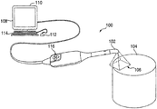
図1は画像キャプチャーシステムを示している。一般に、システム100には、像平面106内の対象物104の画像をキャプチャーして、その画像をコンピュータ108に転送するスキャナー102を搭載してよく、コンピュータ108には、ディスプレイ110と1つ以上の入力用デバイス、例えばマウス112又はキーボード114を搭載してよい。
FIG. 1 shows an image capture system. In general,
スキャナー102には、3次元ポイントクラウドのリカバー元となると思われる画像をキャプチャーするのに適している、いずれかのカメラ又はカメラシステムを搭載することが可能である。例えば、カメラ102には、例えばハート(Hart)らに対する米国特許公開第20040155975号に開示されているようなマルチアパーチャーシステムを採用してよく、前記特許のすべての内容は参照により本明細書に組み込まれる。ハート(Hart)は、1つのマルチアパーチャーシステムを開示しているが、多数の2次元画像から3次元ポイントクラウドを再構成させるのに適しているいずれかのマルチアパーチャーシステムを同様に用いてよいことが分かるであろう。マルチアパーチャーの実施形態の1つでは、スキャナー102には、レンズの中心光軸及びいずれかの付属の画像ハードウェア沿いのセンターアパーチャーといった複数のアパーチャーを搭載してよい。これに加えて、または、これに代えて、スキャナー102には、微妙に異なる多数の透視図から対象物の2次元画像を得るために多数のカメラ又は光パスをそれぞれ一定の関係に保つステレオスコープカメラ、トリスコープカメラ、又は、その他のマルチカメラ若しくはその他の構成を搭載してもよい。スキャナー102には、1つの画像セット又は多数の画像セットから3次元ポイントクラウドを抽出させるのに適している処理を搭載してよく、又は、各2次元画像セットを、以下で説明するコンピュータ108に内臓されているような外部プロセッサに送信してよい。別の実施形態では、スキャナー102では、3次元データ、又は、3次元データに変換することができる2次元データを取得するのに適している構造光、レーザースキャニング、直接測距、又は、その他のいずれかの技術を採用してよい。1つの実施形態では、スキャナー102は、自由に位置づけ可能な手持ち式のプローブのうち、ユーザーが画像捕捉システム100を制御するための、例えば、起動させたりスキャンを停止させたりするためのユーザー入力用デバイス、例えば、ボタン、レバー、ダイヤル、サムホイール、スイッチなどを少なくとも1つ有するプローブである。
The
図1には示されていないが、当然ながら、画像キャプチャー中に、多数の補助照明システムを有用な形で用いてもよい。例えば、対象物104を照らす1つ以上のスポットライトによって周囲照度を上昇させて、画像取得を高速化し、かつ被写界深度(空間分解能の深度)を向上させてよい。これに加えて、又は、これに代えて、スキャナー102に、ストロボ、フラッシュ、又は、その他の光源を搭載して、画像取得中に対象物104の照明を補完してもよい。
Although not shown in FIG. 1, it will be appreciated that a number of auxiliary lighting systems may be used in a useful manner during image capture. For example, the ambient illuminance may be increased by one or more spotlights that illuminate the
対象物104は、いずれかの物体、物体の集合体、物体の一部、又は、その他の対象物にしてよい。図1では、単純な幾何学的形状として図示されているが、対象物104は、これよりもはるかに複雑な表面、及び、いずれかの数の別々の要素を有する。例えば、歯科用イメージング用途では、対象物104としては、歯、歯の4半部、又は、対向する2つの歯列弓(ここから印象材をとるのが望ましい)が含まれている歯群全体が含まれる。これに加えて、又は、これに代えて、対象物104は、歯科補綴物、例えば、インレイ、クラウン、若しくは、その他のいずれかの歯科補綴物、インプラント、又は、同等物を含む。対象物104は、歯科用模型、例えば、1本の歯、複数の歯、軟組織の石膏模型、ワックスアップ、凹凸が逆の印象、又は、これらの組み合わせを含む。特定の例では、3次元の点のキャプチャーを向上させる目的で、光学的又は非平滑化造影剤を対象物104の表面に塗布してよい。別の実施形態では、対象物104は、ヒトの頭又はその一部であってよく、補聴器、眼鏡、ゴーグルなどの用途では、ヒトの頭又はその一部から取った3次元模型が望ましい。別の実施形態では、対象物104は、ミニチュアなど、デジタルアニメーションで用いる物体の物理的模型、3次元デジタルアニメーションプロセスで用いる物理的模型にしてよい。前記の例から、本明細書に記載されている技法を用いるシステムは、レンジが比較的狭い高解像度の3次元画像の取得を目的とした幅広い用途にうまく適応することが可能であることが分かるであろう。ただし、マルチアパーチャー又はマルチカメラシステム、並びに、その他の3次元イメージングシステム及び技術をベースとするその他のさまざまな3次元イメージング用途に対して、画像キャプチャーシステム100への適切な合致がなされると思われ、またこのような変形物がすべて、本開示の範囲内に含まれることを意図していることは、当業者であれば分かるであろう。
The
像平面106としては、カメラ102の2次元視野を含むことが可能である。「像平面」という用語は、本段落で使用する場合、画像をキャプチャーする光学センサー(フィルム又はセンサーなど)内の平面ではなく、イメージング環境内の平面を指すことが分かるであろう。像平面106は矩形で図示されているが、スキャナー102によってもたらされる例えば正方形、円、又は、その他の形状を形成させてよい。一般に、スキャナー102には、スキャナー102の物理的構造と環境条件、例えば周辺光によって決まる像平面106の範囲内の画像取得の被写界深度又は深度分解能レンジを有する。
コンピュータ108は、例えば、パーソナルコンピュータ又はその他の処理デバイスにしてよい。1つの実施形態では、コンピュータ108は、デュアル2.8GHzオプテロン(Opteron)中央演算処理装置、2ギガバイトのランダムアクセスメモリ、タヤンサンダー(TYAN Thunder)K8WEマザーボード、及び、250ギガバイト、10,000rpmのハードドライブを有するパーソナルコンピュータを含む。このシステムを動作させて、本明細書に記載の技法を用いて、リアルタイムで1画像セット当たり約1,500個の点をキャプチャーし、かつ100万個超の点から成る集合体のポイントクラウドを保管することが可能である。さらに一般的には、対象物104のサイズ、画像取得速度、及び、3次元の点の所要空間分解能によって、コンピュータ108の処理能力が変わるであろう。コンピュータ108には、カメラシステム100とのユーザインタラクション用として、キーボード114、ディスプレイ110、及び、マウス112などの周辺機器を搭載してもよい。ディスプレイ110は、ディスプレイ110との直接的かつ物理的インタラクションを通じてユーザー入力を受信可能なタッチスクリーンディスプレイにしてよい。
The
コンピュータ108とスキャナー102の間の通信では、例えば、有線接続、あるいは、例えば、IEEE802.11(無線イーサネット(登録商標)としても知られている)、ブルートゥース、又は、例えば、無線周波、赤外線、若しくは、その他の無線通信媒体を用いるその他のいずれかの適した無線規格を基盤とする無線接続など、いずれかの適した通信リンクを用いてよい。医療上のイメージング又はその他の高感度用途では、スキャナー102から無線で画像をコンピュータ108に転送するようにしてよい。コンピュータ108では、スキャナー102に対する制御信号が生成されるようにすることが可能で、これは、画像取得コマンドに加えて、フォーカス又はズームといった従来型のカメラ制御を含むことが可能である。
For communication between the
3次元画像キャプチャーシステム100の一般的動作の例では、スキャナー102に2次元画像セットを取得させることが可能で、その一方で、スキャナー102を、対象物の表面の上を通過させる。3次元ポイントクラウドを抽出するために、この2次元画像セットをコンピュータ108に転送してよい。新たに取得した2次元画像セットの3次元データは、多種多様の技法を用いて、抽出、及び、既存の3次元データへの合致化すなわち「スティッチング」を行ってよい。このような技法のある有用な例の1つは、同一所有者による米国出願第11/270,135号(2005年11月9日申請)に記載されており、この特許の内容全体は、参照により本明細書に組み込まれる。ただし、この例は本開示を限定するものではなく、本明細書に記載の原理は、広範な3次元画像キャプチャーシステムに適用してよいことは分かるであろう。
In an example of the general operation of the 3D
時々、このようなインクリメンタルなデータ取得システムでは、以下でさらに詳しく説明されている理由により、合致又はスティッチングが成功しない場合がある。このような状況で、ユーザーは、視覚的フィードバックを通じて、リカバーモードが開始されたことを通知されてもよい。リカバーモードでは、システム100が、新たなスキャンデータを、以前取得したデータに試行的に合致させ、かつ視覚的フィードバックをユーザーに提供して、対象物上のスキャン位置に戻るようにナビゲートする(この位置で、以前のスキャン内容の再取得が試みられる)のを支援することによって、以前のスキャン内容を再取得する試みが可能になる。関連するランディングモードでは、ユーザーが、既存の3次元モデルにレジスタ又は接続される新たなスキャンを開始させることが可能である。同様の視覚的フィードバックを提供してユーザーを適切なスキャン位置に誘導し、スキャンが再取得された場合にユーザーに通知することも可能である。これらの技法については以下でさらに詳しく説明するが、まず、スティッチリカバリとランディングのプロセスの詳細な説明から始め、図2及び図3を参照しながら説明する。対応するユーザーインターフェースについては、図4以降の図を参照しながらさらに詳しく説明する。
Sometimes such an incremental data acquisition system may not succeed in matching or stitching for reasons explained in more detail below. In such a situation, the user may be notified that the recovery mode has been initiated through visual feedback. In recover mode, the
図2には、3次元スキャニングのプロセスが描かれている。プロセス200は、工程204に示されているように、センサーから候補フレームを、例えば上記のとおりスキャナー102から画像セットを取得することによって202を始めてよい。プロセス200のこの局面の最中に、ビデオ画像、例えばスキャニングデバイスのある位置又は視点から見た対象物のビデオ画像をディスプレイ110上でレンダリングしてよい。このビューが、画像キャプチャーシステム100のユーザーが、対象物104に対してスキャナー102を配置するのを支援することを可能にする。このような実施形態では、このビューは、ユーザーが対象物104の周辺でスキャナー102を動かすのに応じて連続的にシフトして、スキャナー102の視点の視覚的表示を常に対象物104の上に保持させることになる。別の実施形態では、対象物104は、ディスプレイ100内に静的な非移動性配向で表示させてよく、その一方で、スキャナーの位置及び配向に関係した視覚的キューをユーザーインターフェース内に提供してよい。
FIG. 2 depicts the process of three-dimensional scanning.
工程206で示されているように、候補フレームから3次元データを抽出してよい。言い換えると、画像セットのような2次元データを3次元データ又は3次元画像に変換してよい。本明細書で使用するとき、3次元データ、3次元表示、3次元モデル、3次元画像、3次元表面マップなどの用語は、スキャニングデバイスによってキャプチャーしたインクリメンタルスキャンの結果から作り上げた3次元表示又はその一部を言葉で表す目的で同義的に用いる。ただし、これらの語句の異なる意味が明記されているか、又は、文脈から明らかである場合はこの限りではない。
As indicated at
数多くの技法を用いて、候補フレームから3次元の点の値を算出してよい。例えば、立体照合技法は、画像類似性、例えばピクセル強度の相互情報量又は相関関係の確率的手法を含む。別のタイプの適切な導出法は、例えば、空間的及び/又は時間的勾配を用いるオプティカルフローを含む。ステレオカメラ構成では、例えば、画像セットには典型的に2つの画像が含まれている。ただし、マルチアパーチャーカメラ構成、例えば、3つ又は4つのアパーチャーを有するカメラ、又は、同様のカメラシステムを用いて、3つ以上の画像を画像セットに含めてもよい。さらには、各3次元データセットには、フレーム候補からリカバーされると思われる点のすべて又は大半を含める必要はないことが分かるはずである。ポイントクラウドは、例えば、(元の画像セットのピクセル密度と比べて)候補フレーム画像セットの疎メッシュから算出してよい。この手法は、リアルタイムイメージング用途での処理を加速させるのにとりわけ適していると思われる。疎メッシュは、画像セット内のピクセルのいずれかのサブセットから得ることが可能である。規則正しい方形グリッドは例えば、画像の2段集出を用いる階層化法にとりわけ適している。ただし、例えば三角形、正方形、四辺形などのその他のメッシュを用いて、ポイントクラウドの導出のために画像セット内で規則的又は不規則的間隔のピクセルを選択してもよい。一部の実施形態では、比較的まばらなピクセルデータサブセットをリアルタイムレンダリング及びフィードバック用に用いてよく、その一方で、コンピュータ的にさらに集中的な後処理工程(この工程は、さらに高い精度及び密度を提供することが可能である)で用いるために、もっと緻密又は完璧な形のピクセルデータをストレージ(storage)する。 A number of techniques may be used to calculate a three-dimensional point value from a candidate frame. For example, stereo matching techniques include a probabilistic approach to image similarity, such as mutual information or correlation of pixel intensities. Another type of suitable derivation includes, for example, optical flow using spatial and / or temporal gradients. In a stereo camera configuration, for example, an image set typically includes two images. However, more than two images may be included in the image set using a multi-aperture camera configuration, for example, a camera with three or four apertures, or a similar camera system. Furthermore, it should be appreciated that each three-dimensional data set need not include all or most of the points that are likely to be recovered from the frame candidates. The point cloud may be calculated, for example, from a sparse mesh of the candidate frame image set (compared to the pixel density of the original image set). This approach appears particularly suitable for accelerating processing in real-time imaging applications. A sparse mesh can be obtained from any subset of pixels in the image set. A regular square grid is particularly suitable, for example, for a layering method using a two-stage collection of images. However, other meshes such as triangles, squares, quadrilaterals, etc. may be used to select regular or irregularly spaced pixels in the image set for point cloud derivation. In some embodiments, a relatively sparse pixel data subset may be used for real-time rendering and feedback, while a more computationally intensive post-processing step (which increases the accuracy and density). Storage of more precise or perfect form of pixel data for use.
3次元の点のポイントクラウドから成る3次元表面データは、2次元画像セットから抽出しやすいと思われる3次元データの1つのタイプであることが分かるであろう。ただし、当該技術分野において既知のさまざまな技法を用いて、その他の形態の3次元データを得てもよい。このデータ、は例えば、相互接続している多角形、例えば三角形又はその他の規則的若しくは不規則的な多角形の3次元マップから成る3次元表面データ、あるいは、内部と対象物の表面点を反映しているボリューム3次元データを含むことが可能である。このような変形物はいずれも本開示の範囲内に入るものとして意図している。 It will be appreciated that 3D surface data consisting of a point cloud of 3D points is one type of 3D data that is likely to be extracted from a 2D image set. However, other forms of three-dimensional data may be obtained using various techniques known in the art. This data, for example, reflects 3D surface data consisting of 3D maps of interconnected polygons, such as triangles or other regular or irregular polygons, or surface points of interior and objects Volume three-dimensional data can be included. Any such variations are intended to be within the scope of this disclosure.
工程208に示されているように、3次元データを抽出したら、抽出がうまくいったか判断するために評価を行うことが可能である。一般に、この評価では、インクリメンタルスキャンから再構成した3次元フルモデルとの比較によるのではなく、内部整合性のためにインクリメンタルデータのリカバリを試行する。例えば、対象物から横方向に離れていくスキャナーの動きによって、抽出データが不十分な量になるか、又は、抽出データがまったく得られない場合がある。同様に、特定のイメージング技術では、スキャナーの高速動作によって、取得した2次元画像セット内にブレが生じる場合があり、このブレは、3次元データへの変換の妨げとなる。このモーションブラーは、3次元データの抽出に適さない画像セットをレンダリングするか、又は、抽出した3次元データの品質を低下させる場合がある。スキャナーのその他の動作、例えば、対象物に近すぎたり、対象物から離れすぎるなど、スキャナーの物理的スキャニングレンジ外への動作(これもまた技術依存性である)などによって、低品質又は不十分な抽出3次元データを引き起こす場合がある。その他のイメージングアーチファクトも同様に、3次元データを抽出するのには適さない(又はあまり適さない)特定の画像セット(対象物表面上のテキスチャーの欠如、光の焦点不良又は解像度の不良、鏡面性又はシャドーのような照明異常、光学経路内の構成要素のひずみ及び収差アーチファクトなど)をレンダリングする場合がある。対象物の物理的特性などのその他の要因が、データ取得の低下を引き起こす場合がある。例えば、高反射面は3次元変換の妨げとなる場合がある。成功度に関するさまざまな定量的測度を用いてよく、さまざまな実施形態では、得られる3次元モデルの所望の精度に従ってユーザーが数的閾値を指定してよい。2次元データ(又は、上で概ね説明されているように、その他のセンサーデータ)がうまく3次元データに変換されたことが判明した場合、プロセス200は、工程210に進むことが可能である。2次元データが3次元データにうまく変換されなかったことが判明した場合、プロセスは、工程224に進むことが可能である。
As shown in
工程210では、基準フレーム又は画像(以前に取得済みの画像セット又は抽出済みの3次元データ)があるかどうかに関係して判断を行ってよい。1つの実施形態では、その時点で取得中であるフレームがシーケンス内の第1のフレームである場合を除き、基準フレームは常に利用可能であろう。さまざまな実施形態で、インクリメンタルデータの比較用として、異なるデータタイプ(2次元ソースデータ、変換済み3次元データ点など)を用いてよい。ただし、工程210では、プロセス200は、画像フレームの品質ではなく、基準フレームの存在について試行するに過ぎない。基準フレームが存在する場合には、プロセス200は工程212に進むことが可能である。基準フレームが存在しない場合には、プロセス200は工程220に進むことが可能である。
In
工程212に示されているように、インクリメンタルな3次元画像データは、既存の3次元モデルに合致又はスティッチングさせてよい。1つの実施形態では、このプロセスは、連続的な画像キャプチャーのための位置又は視点の間にスキャナー動作を導き出すことによって行う。ただし、新しい3次元画像の素性を、以前取得した3次元モデルに直接合致させるなどのその他の技法を用いてよい。新しい3次元データを既存の3次元データにレジスタするために有用な形で用いてよいこのような技法はいずれも、本開示の範囲内にあることを意図している。工程212で合致を試みたら、プロセス200は工程214に進めることが可能である。
As shown in
工程214では、工程212で得た合致(この合致は、以前取得した3次元データに追加するまでは、試行的な合致とみなされると思われる)に対し、成功度における試行を行ってよい。試行的な合致では、新たに取得した3次元データの一部又は全部を、以前取得した3次元データと比較するためのあらゆる定量的技法を用いてよい。相関又は素性照合などの試行を用いて、信頼性スコア、又は、合致性に関するその他の客観的尺度を得てよい。さらに、定量限界又はレンジを用いて合致性の成功度を測定する場合、この限界又はレンジは、数的な合致性パラメータの明確な選択、又は、質的な合致性パラメータ(強、中、弱など)の選択のいずれかによってユーザーが制御してよい。さらに、ユーザーの評価及びフィードバックを合致アルゴリズムに組み入れてよく、このアルゴリズムは、例えば、よく再発する合致不良、又は、規定の不具合事象に対応させてよい。工程214では単一の試行的な合致が示されているが、この工程中、あらゆる試行的な合致を行ってもよいことは分かるであろう。この方式では、連続的に取得した多数の3次元画像で、3次元モデルを構築するためにその全部又は一部が用いられる画像のそれぞれを、新たに取得した3次元データに試行的な合致をさせることが可能である。このアプローチは特定の有用性を有し、試行的な合致では、2次元画像セットデータから抽出したいずれかの3次元データの代わりに、又は、この3次元データに加えて、2次元画像セットデータを用いてよい。
In
1つの例示的な実施形態では、多種多様な基準フレーム(本明細書では基準画像ともいう)を試行的な合致のために選択してよい。基準フレームの数は、さまざまな基準を用いて選択してよい。例えば、基準フレームは、新しいインクリメンタルデータに対する時間的近接性に従って選択してよい。すなわち、最新の画像セット又は3次元データセットのグループを試行的な合致のために用いることが可能である。別の例として、新しいインクリメンタルデータに対する空間的近接性に従って基準フレームを選択してよい。すなわち、対象物上における最後の既知の点に最も物理的に近い画像セット又は3次元データセットのグループを用いてよい。候補基準フレームを選択する目的で、画像エントロピー、データ密度、データ量、及び/又は、スキャニングパラメータ(視野内における焦点距離又は位置など)といったその他の技法を単独で又は組み合わせて、適切な形で用いてよい。1つの実施形態では、基準フレームは、3次元モデルを作成する際に用いるインクリメンタルな3次元画像シーケンスの最初の画像から選択して、ユーザーが、元々のスキャンを開始させた位置から再取得を試みることが可能である。1つの実施形態では、基準フレームとして、3次元モデルを作成する際に用いるインクリメンタルな3次元画像シーケンスの最後の画像を選択して、ユーザーが、元々のスキャンが無効になった位置から再取得を試みられるようにしてよい。1つの実施形態では、ユーザーが、試行的な合致のために、3次元モデル上の点又は部分を具体的に選択してよい。このユーザーによる選択を用いて、上記の技法に基づき候補フレームの一群を抽出してよい。手動による選択については、図3のスティッチリカバーモードを参照しながら、さらに詳しく論じていく。一般に、手動による選択は、既存の3次元モデル上の1つ以上の点を選択する目的で、ユーザーインターフェースの操作を通じて実現することが可能である。 In one exemplary embodiment, a wide variety of reference frames (also referred to herein as reference images) may be selected for trial matching. The number of reference frames may be selected using various criteria. For example, the reference frame may be selected according to temporal proximity to new incremental data. That is, the latest image set or group of 3D data sets can be used for trial matching. As another example, a reference frame may be selected according to spatial proximity to new incremental data. That is, an image set or group of three-dimensional data sets that are physically closest to the last known point on the object may be used. Use other techniques alone or in combination, such as image entropy, data density, data volume, and / or other scanning parameters (such as focal length or position in the field of view) to select candidate reference frames You can. In one embodiment, the reference frame is selected from the first image of the incremental 3D image sequence used in creating the 3D model, and the user attempts to reacquire from the location where the original scan was initiated. It is possible. In one embodiment, as the reference frame, the last image of the incremental 3D image sequence used in creating the 3D model is selected and the user re-acquires from the position where the original scan was invalidated. May be tried. In one embodiment, the user may specifically select a point or portion on the three-dimensional model for trial matching. This user selection may be used to extract a group of candidate frames based on the techniques described above. Manual selection will be discussed in more detail with reference to the stitch recovery mode of FIG. In general, manual selection can be achieved through operation of a user interface for the purpose of selecting one or more points on an existing three-dimensional model.
新しい3次元データが既存の3次元データにうまく合致している場合、プロセスを工程216に進めことが可能である。新しい3次元データが既存の3次元データにうまく合致していない場合には、プロセスを工程226に進めてよい。 If the new 3D data matches well with the existing 3D data, the process can proceed to step 216. If the new 3D data does not match the existing 3D data well, the process may proceed to step 226.
工程216に示されているように、新しいか又はインクリメンタルな3次元データを3次元モデルに追加してよい。カメラモーション評価を用いる1つの実施形態では、この工程には、工程218に描かれているように、インクリメンタルな3次元データを3次元モデルの座標系に剛体変換することを含めてよい。ただし、新しい3次元データを既存の3次元データにレジスタするのに適しているいずれかの技法を工程216で有用な形で用いることが可能で、特定の技法の選択は、特定の画像キャプチャーシステムのスキャニングテクノロジー及び/又はセンサーデータに従って変えてよいことが分かるであろう。
As shown in
工程220に示されているように、後にスキャナー102から1つ以上の順編成データセットを取得するのに合わせて、次に、新しいか又はインクリメンタルな3次元データを候補基準フレームとして選択してよい。この時点で、プロセス200を工程222に進めてよい。
As shown in
工程222に示されているように、スキャンが終了したのか判断を行ってよい。これには、例えば、スキャナー102上の入力デバイス116を通じて、マウス112を通じて、キーボード114を通じて、又は、タッチスクリーンの実施形態の場合はディスプレイ110を通じて、受信したユーザー入力を含めてよい。一部の実施形態では、このようなユーザー入力を受容したらいずれかの時点でプロセス200を停止させてよいことが分かるであろう。スキャンが終了したと判断したら、プロセス200を工程228に進めて終了してよい。スキャンが終了していないと判断したら、プロセスを工程204に戻し、新しい候補フレームをスキャナー102から取得してよい。以下の処理工程による後続のパスでは、後続の合致工程用の基準フレームとして、「新たに取得した」3次元データを用いてよい。
As indicated at
工程224で示されているように、3次元データの抽出に失敗した場合(工程214を参照しながら論じたように、ある種の合致の失敗として理解してよい)、プロセス200を進めて、少なくとも1つの基準フレームが存在しているか判断することが可能である。基準フレームがない場合には、プロセスを工程222に進めてから、続いて工程204に進めてよく、工程204では、新しい候補フレームを取得することが可能である。基準フレームが存在する場合には、プロセスを工程226に進めてよく、工程226は、より一般的には、スティッチリカバリモード226を表す。
As shown in
スティッチリカバーモード226では、プロセス200は、新たに取得した各データセットを3次元モデルのある部分に試行的に合致させることによって、スキャンの再取得又は再開を試みることが可能である。この局面の最中、プロセスでは、任意に応じて、順編成のインクリメンタルなデータセットから新しい3次元モデルを作り上げることを開始してよい。この方式では、元の3次元モデルに対する適合性が成功した形で元のスキャンを再取得したら、リカバーモード中に取得した3次元データのすべてを即座に元の3次元モデルにレジスタしてよい。明記されていないが、一部の実施形態では、ユーザーが故意にスキャンを中断させた場合などに、ユーザーがリカバーモード226を手動で選択してよいことが分かるであろう。「再取得」「再開」という用語は、本明細書では、信号劣化のために無効になったスキャンか、ユーザーの操作を通じて明白に停止したスキャンかのいずれかを表す目的で、同義的に用いることに注目するであろう。
In the stitch recover
1つの態様では、本明細書に記載されているプロセス200、及び、このプロセスを具現化させるシステムは、2つの操作モードを有する。取得モードでは、上記のとおり、通常取得、3次元データへの変換、3次元モデルへの試行的な合致が起こることが可能である。リカバーモードでは、又は、下記のランディングモード内で、新たに取得したインクリメンタルデータを3次元モデルに試行的に合致させる。しかしこのインクリメンタルデータを第2のモデルにも合致させて、リカバーモード中に有用な3次元データを引き続き取得できるようにすることが可能で、これについては、図3を参照しながらさらに詳しく説明する。
In one aspect, the
別の態様では、画像キャプチャーシステム100がリカバーモード又は通常取得モードにあるか否かに関係して、モニター110を通じて視覚的キュー又は表示をユーザーに提供してよい。例えば、通常取得モードでは、ディスプレイ100に、スキャナー102から見た場合の対象物104のビデオ画像を表示させてよい。コンピュータで3次元モデルをレンダリングしてよく、この3次元モデルは、対象物104について取得した表面データの3次元ポイントクラウド(ビデオ画像の上に重ねられている)にしてよい。表面データは、シェーディング、又は、ワイヤーフレーム、又は、その他のビジュアル技法によってレンダリングして、表面データの3次元形状を視覚化してよい。このモードでは、ユーザーエクスペリエンスは、取得した3次元モデルを反映する点又はその他の表面レンダリング(多角形など)によって、実質的に対象物104の表面を吹付塗装するというものにしてよい。リカバー(又はランディング)モードでは、コンピュータで、スキャナー102から見た場合の対象物104のビデオ画像をレンダリングしてよいが、コンピュータ108では、3次元モデルのレンダリングを削除又は停止してもよい。これによって、取得が無効になったという即時のユーザーフィードバックを提供してよい。これに加えて、コンピュータでは、スキャナー102の以前の位置、とりわけ、再取得用の基準フレームとして選択した、対象物104上の以前の位置又は場所から、対象物104の以前のビデオ画像をレンダリングして、最新のビデオ画像の上に重ねてよい。以前の場所から見た場合の、重ねたビデオ画像は、異なる色又は異なる不透明度でレンダリングして、最新のビデオ画像から視覚的オフセットを提供することが可能である。以前のビデオ画像を重ねることによって、再取得をアルゴリズム的に試行的に合致させる場所の上でセンタリングした場合、システムは、ユーザーがスキャナー102を対象物104上の所望の位置で再センタリングする補助になるフィードバックをユーザーに提供することができる。つまり、ユーザーに、取得モード及びリカバーモードに関する視覚的キューを提供してよい。リカバーモードは特に、視覚的フィードバックを提供して、ユーザーが元の3次元モデルの3次元データ取得を再取得することを補助することが可能である。その他の技法(方向指示用矢印又は音声キューなど)を用いて、対象物104に対して適切な場所に戻るようユーザーに指示してよいことが分かるであろう。上記のコンピュータ108を用いて、画像キャプチャーと整合するビデオレートで視覚的キュー又は表示をレンダリングして、システムがリアルタイムの視覚的フィードバックをユーザーに提供するようにしてよい。
In another aspect, a visual cue or display may be provided to the user through the
以下では、リカバーモードについてさらに詳しく説明していく。 In the following, the recovery mode will be described in more detail.
図3に示されているように、リカバーモードプロセス300は、スティッチリカバーモード302を開始させることによって始めることが可能である。これは、上述の図2を参照しながら述べた環境のいずれか(ユーザーによるリカバーモードの手動選択など)を通じて発生させてよい。
As shown in FIG. 3, the recover
工程304に示されているように、適切な基準フレームを選択してよい。このフレームには、1つ以上の基準フレームを含めてよく、上で図2の工程214を参照しながら述べた技法のいずれかを用いて選択してよい。リカバーモード用の基準フレームは、図2の取得モード中に作り上げた3次元モデルから選択した基準フレームであることが分かるであろう。1つ以上の基準フレームを選択した後、プロセス300は工程306に進めてよい。
As indicated at
工程306に示されているように、基準フレームをディスプレイに合わせて割り当ててよい。これは、工程304で選択した基準フレームの1つに対応するビデオ画像、及び、本発明のディスプレイでの使用に適したいずれかの対応する2次元又は3次元データにしてよい。さらに一般的には、インクリメンタルデータを合致させる際に用いる特定のイメージング技術及び/又は技法に従って基準フレームの内容を変えてよい。
As indicated in
工程308に示されているように、スキャナー102から新しいデータフレーム(最新のビデオ画像など)を取得してよい。
As shown in
工程310に示されているように、最新のビデオ画像は、工程306で選択した基準ビデオ画像の上に重ねた状態で、モニター110上で表示させてよい。この画像は、ユーザーに対する視覚的表示として、モニター110上で重ねてよい。基準ビデオ画像は、スキャナーの最新の位置からキャプチャーした最新のビデオ画像の上に重ねてよく、各ビデオ画像は、視覚的キュー(色、不透明度など)を利用して区別する。このように重ねることによって、スキャナーが現在どこに配置されているか、及び、スキャンを再取得するにはスキャナーをどこに配置すべきかの双方をユーザーに知らせて、ユーザーが、リカバリに適切な位置にスキャナーを操作するようにしてよい。
As shown in
工程312に示されているように、新しいデータフレームから3次元データを、例えば図2の工程206に関する部分に記載されているように抽出してよい。
As shown in
工程314に示されているように、抽出の成功度を、例えば図2の工程208を参照しながら上述したように評価してよい。抽出がうまくいった場合には、プロセス300を工程316に進めてよい。抽出がうまくいかなかった場合には、プロセス300を工程308に進めてよく、工程308では、新しいデータフレームを取得してよい。
As shown in
工程316に示されているように、図2の工程212を参照しながら上述したような技法を用いて、新たに抽出した3次元データを取得モードの基準フレーム(単一又は複数)に試行的に合致させることが可能である。
As shown in
工程318に示されているように、試行的な合致では、成功度について評価してよい。新しいデータの、基準フレーム(単一又は複数)に対する試行的な合致が成功した場合には、プロセス300を工程320に進めて、リカバーモードを開始させてよい。新しいデータの基準フレーム(単一又は複数)への試行的な合致が成功した場合には、プロセス300を工程308に戻し、工程308で、スキャナー102から新しいデータフレームを取得することが可能である。この時点では、新たに抽出した3次元データを、リカバーモードで以前抽出した3次元データに合致させてよい。この方式では、リカバーモード内で新しい3次元モデルを作成してよい。元々(取得モード)の3次元モデルへの試行的な合致が成功した場合には、うまく合致したフレーム又は3次元画像に基づく変換を用いて、新しい3次元モデル全体、又は、そのうちの選択部分を、元々の3次元モデルにレジスタしてよい。
As shown in
オプティカルフロー技法を用いて、工程212における隣接する画像セット内のピクセル間の対応を割り出すなどすることによって、上記の工程を変えてよいことと、スキャンを停止、開始、若しくは、再始動(リカバー)させる手動入力を提供して、図2に描かれている一連の工程を無効にするなどによって、又は、抽出工程と試行的な合致工程を一緒に行うことによって、工程の順序を変えてよいことは分かるであろう。別の例として、例えば、以前にデータを取得した対象物の部分からスキャンをキャプチャーし、新たにキャプチャーしたスキャンを取得済みの3次元モデルにレジスタすることによって、基準フレームの選択プロセスを自動化してよい。この時点では、試行的な合致及び/又は合致のための後続の基準フレームの選択は、新たに取得したデータのレジスタ位置周辺からキャプチャーした画像セットをベースにすることが可能である。これに加えて、一部の工程を追加若しくは削除してよく、又は、複数の工程を一体化させてもよい。同様に、ある特定のコンピュータ環境では、いくつかの工程を平行して行ってよく(複数の基準フレームに試行的に合致させるなど)、又は、ある特定の工程を1つ以上のプロセス又はプロセッサに分配してよい。1つの変形物では、スキャナーを一定の位置に保持してよく、また、スキャナーの像面内で対象物を動かすことによって、3次元画像キャプチャーを行ってよい。このような変形物及び修正物はすべて、本開示の範囲内に入ることを意図している。
An optical flow technique may be used to alter the above steps, such as by determining the correspondence between pixels in adjacent image sets in
本明細書に記載の3次元イメージング技法に適したハードウェア、ソフトウェア、又は、これらの組み合わせの中で上記のプロセスを実現させてよいことが分かるであろう。前記プロセスは、内部及び/又は外部メモリとともに、1つ以上のマイクロプロセッサ、マイクロコントローラ、組込型マイクロコントローラ、プログラム可能なデジタル信号プロセッサ、又は、プログラム可能なその他のデバイスの中で実現させてよい。これに加えて、又は、この代わりに、前記プロセスには特定用途向け集積回路、プログラム可能なゲートアレイ、プログラム可能なアレイ論理、又は、電子信号を処理するように構成されているその他のいずれかのデバイスを含めてよい。さらには、前記プロセスは、上記デバイスのうちの1つの上で作動させるためにストレージ、コンパイル、又は、読み取られるCなどの構造化プログラミング言語、C++などのオブジェクト指向プログラミング言語、又は、その他の高レベル又は低レベルなプログラミング言語(アセンブリ言語、ハードウェア記述言語、並びに、データベースプログラミング言語及び技術など)のいずれか、並びに、プロセッサ、プロセッサアーキテクチャの不均一な組み合わせ、又は、異なるハードウェアとソフトウェアの組み合わせ、を用いて作成したコンピュータ実行コードとして実現させてよいことが分かるであろう。同時に、処理は、多数の方法でカメラ及び/又はコンピュータにわたって分布させてよく、あるいは、すべての機能性を専用の独立した画像捕捉デバイスに統合させてもよい。このような順列と組み合わせはすべて、本開示の範囲内にあることを意図している。 It will be appreciated that the above process may be implemented in hardware, software, or a combination thereof suitable for the three-dimensional imaging techniques described herein. The process may be implemented in one or more microprocessors, microcontrollers, embedded microcontrollers, programmable digital signal processors, or other programmable devices with internal and / or external memory. . In addition or alternatively, the process may include an application specific integrated circuit, a programmable gate array, programmable array logic, or any other that is configured to process electronic signals. May include other devices. Furthermore, the process may be stored, compiled, or read to operate on one of the devices, a structured programming language such as C, an object oriented programming language such as C ++, or other high level Or any low-level programming language (such as assembly language, hardware description language, and database programming language and technology) and a non-uniform combination of processors, processor architectures, or a combination of different hardware and software, It will be understood that it may be realized as computer-executed code created using At the same time, processing may be distributed across the camera and / or computer in a number of ways, or all functionality may be integrated into a dedicated independent image capture device. All such permutations and combinations are intended to be within the scope of this disclosure.
図2及び図3を参照しながら上で述べたプロセスに関連する工程を行うための手段には、図1を参照しながら上で述べた画像キャプチャーシステム100のいずれかの適切なコンポーネントとともに、このシステムの動作を制御するのに適しているいずれかのソフトウェア及び/又はハードウェアを搭載してよいことも分かるであろう。以下の図は、例えば図1の画像キャプチャーシステム100のディスプレイ110内でレンダリングされると思われるユーザーインターフェースと関連させながら、本明細書で開示するシステム及び方法を説明するものである。
Means for performing steps related to the process described above with reference to FIGS. 2 and 3 include this, along with any suitable components of the
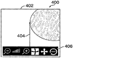
図4は、画像キャプチャーシステム用のユーザーインターフェースの図を示している。ユーザーインターフェース400には、モニター(図1のディスプレイ110など)の上にレンダリングされるウィンドウ402を搭載してよい。ウィンドウ402内では、図1のスキャナー102のようなスキャナーの視野も含め、ビデオ画像を表示してよい。この視野内では、1つ以上のユーザーコントロール406とともに、図1の対象物104のような対象物404を表示してよい。図4は、いずれかの画像取得工程の前のユーザーインターフェースを具体的に示している。したがって、取得済み3次元モデルのレンダリング、又は、基準画像を最新のビデオ画像の上に積み重ねたものはない。
FIG. 4 shows a diagram of a user interface for an image capture system. The
ユーザーコントロール406には一般に、3次元モデルを操作(例えば、回転、拡大縮小、パンなど)したり、ランディング対象を選択したり、画像キャプチャーシステムの動作を制御(例えば、取得の開始又は停止など)したりなどするための1つ以上のコントロールを含めてよい。この1つ以上のコントロールは、例えば、上で図1を参照しながら述べたユーザー入力デバイスのいずれか、例えばモニターとの物理的インタラクション(この場合、ディスプレイ110は、タッチスクリーンを含む)を用いて操作してよい。
User controls 406 generally operate (eg, rotate, scale, pan, etc.) a 3D model, select a landing target, and control the operation of an image capture system (eg, start or stop acquisition) One or more controls may be included to do so. This one or more controls may be performed using, for example, any of the user input devices described above with reference to FIG. 1, for example, physical interaction with a monitor (in this case,
図5は、上で図4を参照しながら説明したような画像キャプチャーシステムの、取得モード状態にあるユーザーインターフェースの図を示している。この図では、1組の3次元の点から成る3次元画像502の初期取得が行われている。この3次元画像、すなわち3次元モデルの第1の要素は、このユーザーインターフェース内で、図5における多数のXによって描かれているように、対象物104の上に重ねるようにレンダリングすることが可能である。これらの点は、後続の3次元画像と区別するためにXとして示されているが、実際には、ユーザーインターフェース内で単に点又はピクセルとしてレンダリングしてよいことは分かるであろう。このようなレンダリングでは、擬似照明によるピクセルのシェーディングなどの技法、又は、キャプチャーした3次元の点の輪郭に関する視覚的キューを提供するその他のいずれかの技法を用いて、ヒトの観察者が、スキャンによってキャプチャーした3次元形状をさらに容易に解釈できるようにしてよい。
FIG. 5 shows a diagram of the user interface in an acquisition mode state of an image capture system as described above with reference to FIG. In this figure, initial acquisition of a three-
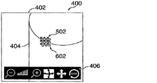
図6は、上で図4〜5を参照しながら説明したような画像キャプチャーシステムの、取得モード状態にあるユーザーインターフェースの図を示している。この図では、1組の3次元の点から成る3次元画像602の第2の取得が行われている。この図における3次元の点の第2のセットは、第1の3次元画像502にうまく合致されており、3次元モデルに追加されている。これらの点は、その他の3次元画像と区別するためにOとして示されているが、実際には、ユーザーインターフェース内で単に点又はピクセルとしてレンダリングしてよいことは分かるであろう。数多くの成功した取得及び合致を通じて、大規模な3次元モデルを取得してよく、また、シェーディングによってポイントクラウドの集合体をレンダリングして、ポイントクラウドの3次元図をシミュレートしてよく、そのすべてを対象物の最新のビデオ画像の上に重ねてよい。
FIG. 6 shows a diagram of the user interface in an acquisition mode state of the image capture system as described above with reference to FIGS. In this figure, a second acquisition of a three-
図7は、上で図4〜6を参照しながら説明したような画像キャプチャーシステムの、リカバーモード状態にあるユーザーインターフェースの図を示している。この図では、十分な3次元データを抽出できなかったか、又は、新しい3次元画像を3次元モデルに合致できなかったなどの理由から、スキャン取得は無効になっている。システムがリカバーモードにあることをユーザーに知らせるために、多数の視覚的キューを提供することが可能である。例えば、図7に示されているように、モデルの3次元の点502、602は削除してよい。別の例として、対象物の以前のビデオ画像702を対象物の最新のビデオ画像404の上に重ねてよい。画像702、404の各々は、その本質を指し示すために、異なる色又は不透明度でレンダリングすることが可能である。このフォーマットでは、ナビゲーション情報が提供される。例えば、最新のビデオ画像404を以前のビデオ画像702と揃えるために、ユーザーは、スキャナーを右に動かしてよい。すなわち、対象物の最新のビデオ画像404を左に移し、以前のビデオ画像702と揃えるようにしてよい。以前のビデオ画像702は、上で図3を参照しながら概ね述べたように、スキャンの再取得用の1つ以上の基準フレームとの関係に従って選択してよい。一般に、以前のビデオ画像702と最新のビデオ画像を揃えたら(拡大縮小及び回転も含む)、新たに取得したセット又は3次元画像が、基準フレームの1つにうまく合致するべきであり、又は、基準フレームの1つにうまく合致する可能性が向上するはずである。これに加えて、又は、この代わりに、図7は、ユーザーがストレージ済み3次元モデル用にスキャンを再取得しようとするランディングモードを示していることは分かるであろう。
FIG. 7 shows a diagram of the user interface in the recover mode state of the image capture system as described above with reference to FIGS. In this figure, scan acquisition is disabled because sufficient 3D data could not be extracted or a new 3D image could not be matched with the 3D model. A number of visual cues can be provided to inform the user that the system is in recover mode. For example, as shown in FIG. 7, the three-
図8は、上で図4〜図7を参照しながら説明したような画像キャプチャーシステムの、リカバーモード状態にあるユーザーインターフェースの図を示している。図8は、図7に対する一般的な比較を提供しており、図7では、ユーザーはスキャナーを操作して、最新のビデオ画像404を以前のビデオ画像702に、さらに近く、整列させている。これに加えて、又は、この代わりに、図8は、ユーザーが、ストレージ済み3次元モデル用にスキャンを再取得しようとするランディングモードを示していることが分かるであろう。
FIG. 8 shows a diagram of the user interface in a recover mode state of the image capture system as described above with reference to FIGS. FIG. 8 provides a general comparison to FIG. 7, in which the user operates the scanner to align the
図9は、上で図4〜図8を参照しながら説明したような画像キャプチャーシステムの、スキャンを再取得した後のユーザーインターフェースの図を示している。この図では、ユーザーが最新のビデオ画像404を再整列させて、新たに取得した3次元画像が基準画像の1つにうまく合致できるようにしている。したがって、リカバーモードを終了させたら、システムは取得モードに戻り、3次元モデルに追加するために追加の3次元データを取得し始める。3次元モデルのポイントクラウド902(任意に応じて、リカバーモード中に取得したデータも含む)を最新のビデオ画像404の上に重ねて、再取得をユーザーに伝える。さらに、この視覚化によって、スキャニングを行った位置と追加のスキャニングが適切であると思われる位置をユーザーに知らせる。
FIG. 9 shows a diagram of the user interface after re-acquiring a scan of an image capture system as described above with reference to FIGS. In this figure, the user has rearranged the
別の実施形態では、ユーザーが、既存の3次元モデルにレジスタ又は接続される新たなスキャンを開始しようとするランディングモードを提供してよい。ランディングモード内で、システムでは任意に応じて、元の3次元モデルにうまく合致させる前に、順次的フレームを相互に合致させることによって補完的な3次元モデルを作成することが可能である。さまざまな実施形態で、スキャンの再取得用に元の3次元モデル上の点を選択するユーザーの能力によって、ランディングモードを区別してよい。 In another embodiment, a user may provide a landing mode that attempts to initiate a new scan that is registered or connected to an existing 3D model. Within the landing mode, the system can optionally create a complementary 3D model by matching sequential frames to each other before successfully matching the original 3D model. In various embodiments, landing modes may be distinguished by the user's ability to select points on the original 3D model for scan reacquisition.
1つの態様では、本明細書に記載のシステム及び方法は、スキャンの無効化及び再取得についてリアルタイムのユーザーフィードバックを提供することによって、リアルタイムのスキャニング動作を向上させる。別の態様では、本明細書に記載のシステム及び方法は、ストレージ済み3次元モデルとともに用いて、画像キャプチャーシステムの機能を強化してよい。このような強化機能の多数の例について以下で説明する。 In one aspect, the systems and methods described herein improve real-time scanning behavior by providing real-time user feedback on scan invalidation and reacquisition. In another aspect, the systems and methods described herein may be used with a stored 3D model to enhance the functionality of an image capture system. A number of examples of such enhancement functions are described below.
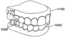
1つの実施形態では、ある物体の複数のスキャン(さまざまな時間に取ったスキャンを含む)を1つのスキャンとして解釈してよい。例えば、歯科用途では、義歯用の表面処理の前と後に、歯の表面をスキャンすることが可能である。第2の処理後スキャンを開始させることによって、歯の未処理表面のスキャンを再取得することによって、処理表面のスキャン前及びスキャン後の構造を合成して、義歯で満たされる空間を取り囲む1つの表面図にしてよい。 In one embodiment, multiple scans of an object (including scans taken at various times) may be interpreted as a single scan. For example, in dental applications, the tooth surface can be scanned before and after the denture surface treatment. By re-acquiring a scan of the untreated surface of the tooth by initiating a second post-process scan, the pre-scan and post-scan structures of the treated surface are combined to enclose a space filled with the denture It may be a surface view.
別の実施形態では、ユーザーインターフェースを修正して、スキャナーの再配向を可能にしてよい。これは、ユーザーが手を変えるか、歯列弓の中間点の周辺にスキャナーを向けるかすることによって、歯列弓のフルスキャンを2等分して行うのが最も利便的である歯科用途でとりわけ有用と思われる。リモートセンサーを歯から離れるように素早く引いてスティッチロスに影響を及ぼすか、「一時停止」ボタン(上記のユーザー入力デバイスのいずれかと思われる)を押すかによって、スキャンを意図的に中断させることができるであろう。この時点で、ユーザーは、スキャン(1つ以上の基準画像を含む)をユーザーインターフェース内で180度(又はその他の角度)の差で再配向してよい。これによって、スティッチリカバリモードにおける表示、及び、画像相関という2つの目的のためにシステム座標を回転させてよい。続いて、オペレーターは、スキャナーを180度回転させて、上記のリカバーモードを用いてスティッチのリカバーを試みることも可能である。スティッチがリカバーしたら、通常の方法でスキャンを進めて、残りの歯をキャプチャーすることができる。 In another embodiment, the user interface may be modified to allow scanner reorientation. This is the most convenient dental application where a full scan of the dental arch is divided into two equal parts by changing the hand or pointing the scanner around the midpoint of the dental arch. It seems to be particularly useful. The scan can be intentionally interrupted by quickly pulling the remote sensor away from the tooth to affect stitch loss or by pressing the “pause” button (which seems to be one of the user input devices above) It will be possible. At this point, the user may re-orient the scan (including one or more reference images) by a 180 degree (or other angle) difference within the user interface. Thus, the system coordinates may be rotated for the two purposes of display in stitch recovery mode and image correlation. Subsequently, the operator can rotate the scanner 180 degrees and attempt to recover the stitch using the above recovery mode. Once the stitch is recovered, the scan can proceed in the usual way to capture the remaining teeth.
別の実施形態では、ユーザーインターフェースを修正して、再取得を試みる場所となる対象物の点又は部分の選択を可能にしてよい。このインターフェースでは、例えばユーザーがインターフェース内で回転、並進、又は、拡大縮小させることが可能な3次元モデルのポイントクラウドを表示させてよい。スキャンのリカバリ用に点又は区域を選択する目的で、コントロール(マウス、キーボード、スキャナー上の入力デバイスを用いるか、タッチスクリーンディスプレイを通じてアクセス可能にしてよい)を提供してよい。上で概ね述べたような選択プロセスを用いて、選択した点に対する空間的又は時間的近接性に従って、又は、いずれかのその他の適切な選択基準に従って、1つ以上の基準フレームを選択してよい。続いて、それまでのスキャンデータから、ユーザーの選択に従って、基準フレーム、画像セット、又は、3次元データを選択してよい。選択プロセスの完了後、ユーザーが、リカバーモードを開始させて、上記の技法を用いて無効になったスティッチをリカバーする試みが可能になる。 In another embodiment, the user interface may be modified to allow selection of a point or portion of the object from which to attempt reacquisition. In this interface, for example, a point cloud of a three-dimensional model that a user can rotate, translate, or scale in the interface may be displayed. Controls (which may be accessible using a mouse, keyboard, input device on the scanner, or accessible through a touch screen display) may be provided for the purpose of selecting points or areas for scan recovery. Using the selection process as generally described above, one or more reference frames may be selected according to spatial or temporal proximity to the selected point, or according to any other suitable selection criteria . Subsequently, a reference frame, an image set, or three-dimensional data may be selected from the previous scan data according to the user's selection. After the selection process is complete, the user can initiate a recover mode to attempt to recover invalid stitches using the techniques described above.
別の実施形態では、本明細書に記載の技法を適用して、3次元画像の連続シーケンスとして3次元データを取得するスキャニングデバイスによって、複雑な表面、関節構造を呈する表面、閉じた面、又は、その他の困難な表面のスキャニングを可能にしてよい。この用途については、以下で、関節構造を呈する1対の歯列弓を参照しながら例示する。 In another embodiment, a scanning device that applies the techniques described herein to acquire 3D data as a continuous sequence of 3D images, a complex surface, a surface that exhibits a joint structure, a closed surface, or Other difficult surface scanning may be enabled. This application is illustrated below with reference to a pair of dental arches that exhibit a joint structure.
図10は、スキャニング対象物の第1の構成要素の3次元図である。第1の構成要素1002は、この図では孤立した状態で、すなわち、第1の構成要素1002と関連のある第2の構成要素(図示なし)から隔離した状態で示されている。この実施例における第1の構成要素1002は、ヒトの歯の下顎歯列弓(周辺軟部組織も含む)である。スキャンの目的では、咬合状態にある歯の下顎及び上顎歯列弓表面マップの取得が可能になる。上記の画像キャプチャーシステム100を用いる歯列弓のスキャンは、歯科患者の口内から歯の露出面の連続スキャン、始点としての利便的ないずれかの位置の選択、及び、いずれかの露出部分を横切るスキャン経路1106内での進行、外面上の別の位置1008での終了を含むことが可能である。この時点で、スキャンを手動で終了させるか、又は、第1の構成要素1002用のスキャニング範囲の外にスキャナーを素早く移動させるなどの操作を通じてスキャンを終了させてよい。上記のリカバーモードの実施形態の1つによれば、このスキャンの最後に1つ以上の基準フレームを確立させてよい。露出面をスキャニングすることによって、第1の構成要素1002、すなわち下顎歯列弓の完全な3次元表面スキャンを取得してよい。同時に、所望の位置でこのシステムを強制的にリカバリモードにすることによって、利便的な再取得点を確立することが可能である。図示されているようにスキャン経路1006は歯列弓の下を通る(これは歯科用モデルにふさわしいと思われる)が、口腔内でキャプチャーする患者の歯のライブスキャンは典型的に露出面を横切るだけであることが評価されるであろう。
FIG. 10 is a three-dimensional view of the first component of the scanning object. The
図11は、スキャニング対象物の第1及び第2の構成要素の3次元図である。第1の構成要素1002は、図10の下顎歯列弓にしてよい。第2の構成要素1102は、前記下顎歯列弓と咬合状態にある上顎歯列弓にしてよい。リカバーモードから第2のスキャンを開始する際、第1のスキャンを終了させた下顎歯列弓上の位置1008の周辺でスキャンを再取得してよい。続いて、スキャンを第2の構成要素上の位置1104の上へと続け、位置1104で、スキャンをリカバーモード状態で再び終了させてよい。
FIG. 11 is a three-dimensional view of the first and second components of the scanning object. The
図12は、スキャニング対象物の第2の構成要素の3次元図である。図12は、第2の構成要素1102を孤立した状態で示している。矢印1201は、前にスキャンが終了した位置1104で第3のスキャンを開始することを示している。リカバーモード内からこの位置1104でスキャンを再取得してよい。スティッチリカバリ後、第2の構成要素の一部又は全部のスキャンを完了させて、その構成要素の表面上の位置1202で終結するようにしてよい。第2の構成要素1102を取り囲むように概ね描かれているが、ヒトの歯の口内スキャンのような表面スキャンは典型的に露出面に対してのみ可能であることが分かるであろう。この方式でスキャニングすると、上顎歯列弓に関する完全な3次元表面マップを得ることが可能で、咬合状態の下顎歯列弓は、ヒトの歯の一連の口内スキャンから得られる場合がある。この、咬合レジストレーションのデジタルバージョンは、1つ以上の閉塞した歯表面を伴う義歯の製作で有用である場合がある。さらに一般的には、この技法は、数多くのスキャニング環境に適切な形で合致させてよい。例えば、この技法を適用して、蓋、又は、内側部分にアクセスするために分離させてよいその他の構成要素を有する密閉した箱の内側及び外側の3次元表面のフルスキャンを得ることが可能である
FIG. 12 is a three-dimensional view of the second component of the scanning object. FIG. 12 shows the
図10〜図12を参照しながら述べた技法では、スティッチングが無効になった区域から基準フレームを選択するリカバーモードを利用するが、数多くの合致物及び変形物が可能であることが分かるであろう。例えば、1つの実施形態では、取得が無効化したスキャンの開始点と終結点についてリカバーモードで試行的に合致させることが可能である。このようなリカバーモードを用いる場合、この技法は、一定の関係にある2つの物体に及ぶスキャンから始めてよく、このスキャンは、第1の物体上から始め、第2の物体上で終結する。これらの物体を分離させたら、最初のスキャンの開始点及び終結点から2つの別々のリカバリを開始させてよい。別の実施形態では、基準フレーム用の点の選択を可能にするユーザーインターフェースを用いて、多種多様なスキャン順序を可能にしてよい。ただし、少なくとも1つのスキャンが、所望の配向で双方の物体に及ぶことを条件とする。さらなる変形物では、上記の技法の直接的な拡張によって、いずれかの数の別々の物体を1つ以上の配向で順次的に、又は、その他の形でスキャンしてよい。したがって、本明細書では、剛体であると思われる複数の物体を相互に一定の配向でスキャニングするためのシステム及び方法を開示する。 Although the technique described with reference to FIGS. 10-12 utilizes a recover mode that selects a reference frame from an area where stitching has been disabled, it will be appreciated that many matches and variations are possible. I will. For example, in one embodiment, the start and end points of a scan for which acquisition has been invalidated can be trial matched in recover mode. When using such a recovery mode, the technique may start with a scan that spans two objects in a fixed relationship, starting from a first object and ending on a second object. Once these objects are separated, two separate recoveries may be initiated from the beginning and end of the first scan. In another embodiment, a wide variety of scan orders may be enabled using a user interface that allows selection of points for the reference frame. Provided that at least one scan spans both objects in the desired orientation. In further variations, any number of separate objects may be scanned sequentially in one or more orientations, or otherwise, by direct extension of the above technique. Accordingly, disclosed herein is a system and method for scanning a plurality of objects that appear to be rigid with respect to each other in a fixed orientation.
特定の好ましい実施形態と関連させながら本発明を開示してきたが、当業者であれば別の実施形態を認識するであろうし、そのような変形物、修正物、及び、代用物は、本開示の範囲内に含まれると意図している。したがって、本発明は請求項を参照しながら理解するものとし、この請求項は法律によって許される最も広い意味で解釈するものとする。 While the present invention has been disclosed in connection with certain preferred embodiments, those skilled in the art will recognize other embodiments, and such variations, modifications, and alternatives are disclosed in the present disclosure. It is intended to be included within the scope of Accordingly, the invention is to be understood with reference to the following claims, which are to be construed in the broadest sense permitted by law.
本発明及び本発明の詳細な説明は、以下の図を参照することによって理解してよい。 The invention and detailed description thereof may be understood by reference to the following figures.
Claims (101)
次の3次元画像のための画像セットを取得する工程と、
前記画像セットを前記次の3次元画像に変換でき、かつ前記次の3次元画像を3次元表面データに合致させることができる場合に、3次元表面データと前記次の3次元画像をディスプレイ内で対象物の2次元画像の上に重ねる工程と、
前記画像セットを前記次の3次元画像に変換できない、又は前記次の3次元画像を前記3次元表面データに合致させることができない場合に、リカバーモードを開始する工程とを含む方法であって、
前記リカバーモードが、
前記対象物の最新の2次元画像をディスプレイ内で前記対象物の以前の2次元画像の上に重ねる工程であって、前記以前の2次元画像が前記3次元画像シーケンスのうちの1つの画像を取得した位置から見た前記対象物の画像を表し、前記最新の2次元画像が前記画像セットを取得した位置から見た前記対象物の画像を表す、工程と、
少なくとも1つの後続の3次元画像を取得する工程と、
前記少なくとも1つの後続の3次元画像を前記3次元画像シーケンスの画像の1つ以上に試行的に合致させる工程とを含む、方法。 Obtaining three-dimensional surface data from the object as a three-dimensional image sequence, each image of the three-dimensional image sequence matching at least one previous image of the three-dimensional image sequence;
Obtaining an image set for the next three-dimensional image;
If the image set can be converted to the next 3D image and the next 3D image can be matched to 3D surface data, the 3D surface data and the next 3D image are displayed in the display. Superimposing on a two-dimensional image of the object;
Starting the recovery mode when the image set cannot be converted into the next three-dimensional image or when the next three-dimensional image cannot be matched with the three-dimensional surface data,
The recover mode is
Superimposing a latest two-dimensional image of the object on a previous two-dimensional image of the object in a display, wherein the previous two-dimensional image represents one image of the three-dimensional image sequence. Representing the image of the object viewed from the acquired position, the latest two-dimensional image representing the image of the object viewed from the position from which the image set was acquired; and
Obtaining at least one subsequent three-dimensional image;
Trial matching the at least one subsequent 3D image with one or more of the images of the 3D image sequence.
試行的な合致が、試行的な合致のための適合性に基づき前記3次元画像シーケンスから基準画像を選択する工程を含む、請求項1に記載の方法。 The recovering mode includes trial matching at least one subsequent three-dimensional image with one or more additional images acquired during the recovering mode;
The method of claim 1, wherein trial matching includes selecting a reference image from the three-dimensional image sequence based on suitability for trial matching.
対象物の3次元画像用の画像セットを取得する工程と、
前記画像セットを前記3次元表面データに合致させることができない場合に、ランディングモードを開始させる工程とを含む方法であって、
前記ランディングモードが、
前記対象物の最新の2次元画像を前記ディスプレイ内で前記対象物の以前の2次元画像の上に重ねるステップであって、前記最新の2次元画像が前記画像セットを取得した位置から見た前記対象物の画像を表し、前記以前の2次元画像が前記3次元表面データの少なくとも一部を取得した位置から見た前記対象物の画像を表す、ステップと、
少なくとも1つの後続の3次元画像を取得する工程と、
前記少なくとも1つの後続の3次元画像を第2の3次元表面再構成物に合致させるステップと、
前記少なくとも1つの後続の3次元画像を前記3次元表面データに試行的に合致させるステップと、
前記画像セットを前記3次元表面データに合致可能な場合に、前記3次元表面データと前記次の3次元画像をディスプレイ内で前記対象物の2次元画像の上に重ね、かつ前記第2の3次元表面再構成物を前記3次元表面データに追加するステップとを有する、方法。 Providing three-dimensional surface data of the object;
Obtaining an image set for a three-dimensional image of the object;
Initiating a landing mode if the image set cannot be matched to the three-dimensional surface data,
The landing mode is
Overlaying the latest two-dimensional image of the object on the previous two-dimensional image of the object in the display, wherein the latest two-dimensional image is viewed from the position from which the image set was acquired. Representing an image of an object, wherein the previous two-dimensional image represents an image of the object viewed from a position from which at least a portion of the three-dimensional surface data was acquired;
Obtaining at least one subsequent three-dimensional image;
Matching the at least one subsequent 3D image to a second 3D surface reconstruction;
Trial matching the at least one subsequent 3D image with the 3D surface data;
If the image set can be matched to the 3D surface data, the 3D surface data and the next 3D image are superimposed on the 2D image of the object in a display, and the second 3D Adding a three-dimensional surface reconstruction to the three-dimensional surface data.
前記取得モードと前記リカバリモードとを区別するための1つ以上の視覚的インジケータを提供するようになされたディスプレイとを含む、システム。 A scanning device for acquiring 3D surface data from an object as a 3D image sequence, wherein each image of the 3D image sequence matches at least one of the previous images of the 3D image sequence, and one or more Having an acquisition mode of acquiring and adding to the 3D surface data one or more additional 3D images to one or more images of the 3D image sequence A device that has a recovery mode that recovers the acquisition mode to match
And a display adapted to provide one or more visual indicators for distinguishing between the acquisition mode and the recovery mode.
前記第1の対象物に対して一定の配向で第2の対象物を配置する工程と、
前記第1の対象物の表面上の位置から始まり前記第2の対象物の少なくとも一部を含む第2の3次元データセットの第2の取得を行う工程とを含む、方法。 Performing a first acquisition of a first three-dimensional data set from a first object;
Disposing a second object in a fixed orientation relative to the first object;
Performing a second acquisition of a second three-dimensional data set starting from a position on the surface of the first object and including at least a portion of the second object.
前記第1の対象物を取り除く工程と、
前記第2の対象物の表面上の前記位置から始まる3次元データの第3の取得を行う工程とをさらに含む、請求項35に記載の方法。 Ending the second acquisition at a position on the surface of the second object;
Removing the first object;
36. The method of claim 35, further comprising performing a third acquisition of three-dimensional data starting from the position on the surface of the second object.
前記第1の対象物に対して一定の配向で第2の対象物を配置する配置手段とを含むシステムであって、
前記取得手段が、前記第1の対象物の表面上の位置から始まり、かつ前記第2の対象物の少なくとも一部を含む、第2の3次元データセットの第2の取得を行う手段を含む、システム。 An acquisition means for performing a first acquisition of a first three-dimensional data set from a first object;
A placement means for placing a second object in a fixed orientation relative to the first object,
The acquisition means includes means for performing a second acquisition of a second three-dimensional data set starting from a position on the surface of the first object and including at least a portion of the second object. ,system.
前記第1の対象物を取り除く手段を含む前記配置手段と、
前記第2の対象物の表面上の位置から始まる3次元データの第3の取得を行う手段を含む前記取得手段とをさらに備える、請求項46に記載のシステム。 Control means for terminating the second acquisition at a position on the surface of the second object;
The placement means including means for removing the first object;
47. The system of claim 46, further comprising the acquisition means including means for performing a third acquisition of three-dimensional data starting from a position on the surface of the second object.
前記第1の対象物の第1の部分と前記第2の対象物の第1の部分とを含む第1の3次元データセットを取得する工程と、
前記第1の対象物の表面上の位置から始まり前記第1の対象物の前記第1の部分とは異なる前記第1の対象物の第2の部分を含む第2の3次元データセットを、孤立状態の前記第1の対象物から取得する工程と、
前記第1の3次元データを前記第2の3次元データと合成する工程とを含む、方法。 Placing the first object in a fixed orientation relative to the second object;
Obtaining a first three-dimensional data set comprising a first part of the first object and a first part of the second object;
A second three-dimensional data set comprising a second part of the first object starting from a position on the surface of the first object and different from the first part of the first object; Obtaining from the first object in an isolated state;
Combining the first three-dimensional data with the second three-dimensional data.
前記第3の3次元データセットを前記第1及び前記第2の3次元データセットと合成する工程とをさらに含む、請求項57に記載の方法。 Obtaining a third three-dimensional data set from the isolated second object starting from a position on the surface of the second object and including a second portion of the second object; ,
58. The method of claim 57, further comprising combining the third three-dimensional data set with the first and second three-dimensional data sets.
前記対象物をスキャニングして、1つ以上の追加の3次元画像を取得する工程と、
前記1つ以上の追加の3次元画像の各画像を前記3次元データセットに試行的に合致させる工程と、
合致が成功した場合に、前記1つ以上の追加の3次元画像を前記3次元データセットに追加する工程とを含む、方法。 Providing a first three-dimensional data set from an object;
Scanning the object to obtain one or more additional three-dimensional images;
Trial matching each image of the one or more additional three-dimensional images with the three-dimensional data set;
Adding the one or more additional three-dimensional images to the three-dimensional data set if a match is successful.
合致が成功した場合に、前記第2の3次元データセットを前記第1の3次元データセットに追加する工程とをさらに含む、請求項66に記載の方法。 Matching each of the new ones of the one or more additional three-dimensional images to each other to provide a second three-dimensional data set;
68. The method of claim 66, further comprising: adding the second three-dimensional data set to the first three-dimensional data set if a match is successful.
前記対象物をスキャニングして1つ以上の追加の3次元画像を取得する取得手段と、
前記1つ以上の追加の3次元画像の各々を前記3次元データセットに試行的に合致させるコンピューティング手段であって、さらに、合致が成功したことを検出し、合致が成功したことを検出した場合に、前記1つ以上の追加の3次元画像を前記3次元データセットに追加する手段とを備えた、システム。 Storage means for providing a first three-dimensional data set from an object;
Obtaining means for scanning the object to obtain one or more additional three-dimensional images;
Computing means for trial matching each of the one or more additional three-dimensional images with the three-dimensional data set, further detecting successful matching and detecting successful matching And means for adding the one or more additional three-dimensional images to the three-dimensional data set.
対象物から第1の3次元データセットを提供するステップと、
前記対象物をスキャニングして、1つ以上の追加の3次元画像を取得するステップと、
前記1つ以上の追加の3次元画像の各々を、前記3次元データセットに試行的に合致させるステップと、
合致が成功した場合に、前記1つ以上の追加の3次元画像を前記3次元データセットに追加するステップとを実行させる、コンピュータプログラム製品。 A computer program product embodied on a computer-readable medium and comprising computer-executable code when the product is executed on one or more computing devices,
Providing a first three-dimensional data set from the object;
Scanning the object to obtain one or more additional three-dimensional images;
Trial matching each of the one or more additional three-dimensional images with the three-dimensional data set;
A computer program product that, if successful, adds the one or more additional three-dimensional images to the three-dimensional data set.
前記対象物をスキャニングして、1つ以上の追加の3次元画像を取得する工程と、
前記1つ以上の追加の3次元画像の各画像を前記3次元データセットにリアルタイムで試行的に合致させる工程と、
試行的な合致に関係したリアルタイムの視覚的フィードバックをユーザーに提供する工程とを含む、方法。 Providing a first three-dimensional data set from an object;
Scanning the object to obtain one or more additional three-dimensional images;
Trial matching each image of the one or more additional three-dimensional images with the three-dimensional data set in real time;
Providing the user with real-time visual feedback related to the trial match.
合致が成功した場合に、前記第2の3次元データセットを前記第1の3次元データセットに追加する工程をさらに含む、請求項81に記載の方法。 Matching each of the one or more new images of the one or more additional three-dimensional images to each other to provide a second three-dimensional data set if a trial match is not successful;
82. The method of claim 81, further comprising adding the second three-dimensional data set to the first three-dimensional data set if a match is successful.
前記対象物をスキャニングして1つ以上の追加の3次元画像を取得する取得手段と、
前記1つ以上の追加の各3次元画像を前記第1の3次元データセットにリアルタイムで試行的に合致させるコンピューティング手段と、
試行的な合致に関係したリアルタイムの視覚的フィードバックをユーザーに提供する表示手段とを備える、システム。 Storage means for providing a first three-dimensional data set from an object;
Obtaining means for scanning the object to obtain one or more additional three-dimensional images;
Computing means for trial matching the one or more additional three-dimensional images with the first three-dimensional data set in real time;
And a display means for providing the user with real-time visual feedback related to the trial match.
合致が成功した場合に、前記第2の3次元データセットを前記第1の3次元データセットに追加する手段とを備える、請求項88に記載のシステム。 The computing means matches each of the new images of the one or more additional three-dimensional images to each other to provide a second three-dimensional data set if a trial match is not successful. Means to
90. The system of claim 88, comprising means for adding the second three-dimensional data set to the first three-dimensional data set if a match is successful.
対象物から第1の3次元データセットを提供するステップと、
前記対象物をスキャニングして、1つ以上の追加の3次元画像を取得するステップと、
前記1つ以上の追加の3次元画像の各々を、前記第1の3次元データセットにリアルタイムで試行的に合致させるステップと、
試行的な合致に関係したリアルタイムの視覚的フィードバックをユーザーに提供するステップとを実行させる、コンピュータプログラム製品。 A computer program product comprising computer-executable code embodied on a computer-readable medium when the product is executed on one or more computing devices;
Providing a first three-dimensional data set from the object;
Scanning the object to obtain one or more additional three-dimensional images;
Trial matching each of the one or more additional three-dimensional images to the first three-dimensional data set in real time;
Providing a user with real-time visual feedback related to the trial match.
合致が成功した場合に、前記第2の3次元データセットを前記第1の3次元データに追加するステップとを実行させるコンピュータコードをさらに含む、請求項95に記載のコンピュータプログラム製品。 Matching each of the one or more new images of the one or more additional three-dimensional images to each other to provide a second three-dimensional data set if a trial match is not successful;
96. The computer program product of claim 95, further comprising computer code that, when a match is successful, causes the step of adding the second three-dimensional data set to the first three-dimensional data.
Applications Claiming Priority (2)
| Application Number | Priority Date | Filing Date | Title |
|---|---|---|---|
| US11/337,182 US8035637B2 (en) | 2006-01-20 | 2006-01-20 | Three-dimensional scan recovery |
| PCT/US2007/001287 WO2007084589A2 (en) | 2006-01-20 | 2007-01-19 | Three-dimensional scan recovery |
Publications (2)
| Publication Number | Publication Date |
|---|---|
| JP2009523547A true JP2009523547A (en) | 2009-06-25 |
| JP2009523547A5 JP2009523547A5 (en) | 2010-03-04 |
Family
ID=38197780
Family Applications (1)
| Application Number | Title | Priority Date | Filing Date |
|---|---|---|---|
| JP2008551367A Withdrawn JP2009523547A (en) | 2006-01-20 | 2007-01-19 | 3D scan recovery |
Country Status (4)
| Country | Link |
|---|---|
| US (2) | US8035637B2 (en) |
| EP (6) | EP2620913B1 (en) |
| JP (1) | JP2009523547A (en) |
| WO (1) | WO2007084589A2 (en) |
Cited By (9)
| Publication number | Priority date | Publication date | Assignee | Title |
|---|---|---|---|---|
| JP2009078133A (en) * | 2007-08-16 | 2009-04-16 | Steinbichler Optotechnik Gmbh | Device for determining 3d coordinates of object, in particular of tooth |
| JP2010154920A (en) * | 2008-12-26 | 2010-07-15 | Canon Inc | Three-dimensional shape data processor, three-dimensional shape data processing method, and program |
| WO2011007632A1 (en) * | 2009-07-13 | 2011-01-20 | Canon Kabushiki Kaisha | Tomography apparatus and tomogram correction processing method |
| JP2014094228A (en) * | 2012-11-12 | 2014-05-22 | Canon Inc | Subject information acquiring apparatus and control method therefor |
| WO2017057330A1 (en) * | 2015-09-28 | 2017-04-06 | オリンパス株式会社 | Endoscope system and image processing method |
| JP2019126705A (en) * | 2018-01-25 | 2019-08-01 | 廣達電腦股▲ふん▼有限公司 | Device and method of three-dimensional image processing |
| JP2021007739A (en) * | 2019-06-14 | 2021-01-28 | ジーイー・プレシジョン・ヘルスケア・エルエルシー | Method and system for generating target 3d point cloud in medical imaging system |
| JP2021111254A (en) * | 2020-01-15 | 2021-08-02 | 株式会社モリタ製作所 | Information processing apparatus and data processing method |
| KR20210130111A (en) * | 2020-04-21 | 2021-10-29 | 주식회사 메디트 | Align-state indicating apparatus and method thereof |
Families Citing this family (126)
| Publication number | Priority date | Publication date | Assignee | Title |
|---|---|---|---|---|
| US8035637B2 (en) * | 2006-01-20 | 2011-10-11 | 3M Innovative Properties Company | Three-dimensional scan recovery |
| US8043091B2 (en) | 2006-02-15 | 2011-10-25 | Voxelogix Corporation | Computer machined dental tooth system and method |
| US8366442B2 (en) | 2006-02-15 | 2013-02-05 | Bankruptcy Estate Of Voxelogix Corporation | Dental apparatus for radiographic and non-radiographic imaging |
| WO2011017393A1 (en) | 2009-08-04 | 2011-02-10 | Eyecue Vision Technologies Ltd. | System and method for object extraction |
| US7835811B2 (en) | 2006-10-07 | 2010-11-16 | Voxelogix Corporation | Surgical guides and methods for positioning artificial teeth and dental implants |
| WO2008098340A1 (en) * | 2007-02-16 | 2008-08-21 | Countlab Inc. | A container filling machine |
| US7916911B2 (en) | 2007-02-26 | 2011-03-29 | Align Technology, Inc. | System and method for digital tooth imaging |
| US20090061381A1 (en) * | 2007-09-05 | 2009-03-05 | Duane Milford Durbin | Systems and methods for 3D previewing |
| US8456471B2 (en) | 2008-08-26 | 2013-06-04 | Leica Geosystems | Point-cloud clip filter |
| DE102008054985B4 (en) | 2008-12-19 | 2012-02-02 | Sirona Dental Systems Gmbh | Method and device for optical measurement of three-dimensional objects by means of a dental 3D camera using a triangulation method |
| US8908995B2 (en) | 2009-01-12 | 2014-12-09 | Intermec Ip Corp. | Semi-automatic dimensioning with imager on a portable device |
| US10603008B2 (en) * | 2009-02-19 | 2020-03-31 | Tessonics Corporation | Ultrasonic device for assessment of internal tooth structure |
| WO2010142929A1 (en) * | 2009-06-11 | 2010-12-16 | Toshiba Research Europe Limited | 3d image generation |
| ES2607052T3 (en) | 2009-06-17 | 2017-03-29 | 3Shape A/S | Focus scanning apparatus |
| US9595108B2 (en) | 2009-08-04 | 2017-03-14 | Eyecue Vision Technologies Ltd. | System and method for object extraction |
| US9159130B2 (en) | 2009-10-22 | 2015-10-13 | Koninklijke Philips N.V. | Alignment of an ordered stack of images from a specimen |
| US8348669B1 (en) | 2009-11-04 | 2013-01-08 | Bankruptcy Estate Of Voxelogix Corporation | Surgical template and method for positioning dental casts and dental implants |
| JP5655134B2 (en) | 2010-03-31 | 2015-01-14 | オムロン サイエンティフィック テクノロジーズ, インコーポレイテッドOmron Scientific Technologies, Inc. | Method and apparatus for generating texture in 3D scene |
| DE102010020925B4 (en) | 2010-05-10 | 2014-02-27 | Faro Technologies, Inc. | Method for optically scanning and measuring an environment |
| EP3813027A1 (en) * | 2010-07-19 | 2021-04-28 | Align Technology, Inc. | Methods and systems for creating and interacting with three dimensional virtual models |
| US20120062557A1 (en) * | 2010-09-10 | 2012-03-15 | Dimensional Photonics International, Inc. | Systems and methods for processing and displaying intra-oral measurement data |
| US9599461B2 (en) | 2010-11-16 | 2017-03-21 | Ectoscan Systems, Llc | Surface data acquisition, storage, and assessment system |
| US11880178B1 (en) | 2010-11-16 | 2024-01-23 | Ectoscan Systems, Llc | Surface data, acquisition, storage, and assessment system |
| ES2788853T3 (en) * | 2010-12-06 | 2020-10-23 | 3Shape As | System with 3D user interface integration |
| EP2649409B1 (en) * | 2010-12-06 | 2018-10-17 | 3Shape A/S | System with 3d user interface integration |
| WO2012083968A1 (en) | 2010-12-21 | 2012-06-28 | 3Shape A/S | Motion blur compensation |
| US9191648B2 (en) | 2011-02-22 | 2015-11-17 | 3M Innovative Properties Company | Hybrid stitching |
| WO2012115862A2 (en) | 2011-02-22 | 2012-08-30 | 3M Innovative Properties Company | Space carving in 3d data acquisition |
| US10157495B2 (en) | 2011-03-04 | 2018-12-18 | General Electric Company | Method and device for displaying a two-dimensional image of a viewed object simultaneously with an image depicting the three-dimensional geometry of the viewed object |
| US9984474B2 (en) * | 2011-03-04 | 2018-05-29 | General Electric Company | Method and device for measuring features on or near an object |
| US10019812B2 (en) * | 2011-03-04 | 2018-07-10 | General Electric Company | Graphic overlay for measuring dimensions of features using a video inspection device |
| US10586341B2 (en) * | 2011-03-04 | 2020-03-10 | General Electric Company | Method and device for measuring features on or near an object |
| US8900126B2 (en) | 2011-03-23 | 2014-12-02 | United Sciences, Llc | Optical scanning device |
| DK2732434T3 (en) * | 2011-07-15 | 2018-12-17 | 3Shape As | DETECTING A MOVABLE ITEM BY 3D SCANNING OF A RIGGET ITEM |
| KR101859412B1 (en) * | 2011-09-05 | 2018-05-18 | 삼성전자 주식회사 | Apparatus and method for converting 2d content into 3d content |
| US9691176B2 (en) * | 2011-11-17 | 2017-06-27 | Techmed 3D Inc. | Method and system for forming a virtual model of a human subject |
| US20130183633A1 (en) * | 2012-01-13 | 2013-07-18 | Ormco Corporation | System and method for three-dimensional intra-oral imaging |
| DE102012201193B3 (en) * | 2012-01-27 | 2013-06-13 | Sirona Dental Systems Gmbh | Method and reference model for checking a surveying system |
| US9339249B2 (en) * | 2012-02-24 | 2016-05-17 | Kabushiki Kaisha Toshiba | Medical image processing apparatus |
| US8900125B2 (en) | 2012-03-12 | 2014-12-02 | United Sciences, Llc | Otoscanning with 3D modeling |
| US20130293686A1 (en) * | 2012-05-03 | 2013-11-07 | Qualcomm Incorporated | 3d reconstruction of human subject using a mobile device |
| US9779546B2 (en) * | 2012-05-04 | 2017-10-03 | Intermec Ip Corp. | Volume dimensioning systems and methods |
| US10007858B2 (en) | 2012-05-15 | 2018-06-26 | Honeywell International Inc. | Terminals and methods for dimensioning objects |
| US8992224B2 (en) * | 2012-08-15 | 2015-03-31 | Kerrhawe Sa | Scanning polymerization of dental material |
| US10321127B2 (en) | 2012-08-20 | 2019-06-11 | Intermec Ip Corp. | Volume dimensioning system calibration systems and methods |
| EP2700377A1 (en) * | 2012-08-20 | 2014-02-26 | Heraeus Kulzer GmbH | Scannable body for determining the orientation and position of a dental implant |
| US9939259B2 (en) | 2012-10-04 | 2018-04-10 | Hand Held Products, Inc. | Measuring object dimensions using mobile computer |
| US10067231B2 (en) | 2012-10-05 | 2018-09-04 | Faro Technologies, Inc. | Registration calculation of three-dimensional scanner data performed between scans based on measurements by two-dimensional scanner |
| DE102012109481A1 (en) | 2012-10-05 | 2014-04-10 | Faro Technologies, Inc. | Device for optically scanning and measuring an environment |
| US20140104413A1 (en) | 2012-10-16 | 2014-04-17 | Hand Held Products, Inc. | Integrated dimensioning and weighing system |
| US8948482B2 (en) * | 2012-11-01 | 2015-02-03 | Align Technology, Inc. | Motion compensation in a three dimensional scan |
| US9129435B2 (en) * | 2012-12-04 | 2015-09-08 | Fuji Xerox Co., Ltd. | Method for creating 3-D models by stitching multiple partial 3-D models |
| US10617489B2 (en) | 2012-12-19 | 2020-04-14 | Align Technology, Inc. | Creating a digital dental model of a patient's teeth using interproximal information |
| US10098714B2 (en) | 2012-12-19 | 2018-10-16 | Align Technology, Inc. | Apparatus and method for optically scanning an object in registration with a reference pattern |
| US9091628B2 (en) | 2012-12-21 | 2015-07-28 | L-3 Communications Security And Detection Systems, Inc. | 3D mapping with two orthogonal imaging views |
| DE102014102206B4 (en) * | 2013-03-08 | 2016-05-12 | Jörg Bressem | Method for producing a dental component and dental component |
| US10278584B2 (en) | 2013-03-11 | 2019-05-07 | Carestream Dental Technology Topco Limited | Method and system for three-dimensional imaging |
| WO2014139079A1 (en) * | 2013-03-11 | 2014-09-18 | Carestream Health, Inc. | A method and system for three-dimensional imaging |
| US9080856B2 (en) | 2013-03-13 | 2015-07-14 | Intermec Ip Corp. | Systems and methods for enhancing dimensioning, for example volume dimensioning |
| CN104042352B (en) * | 2013-03-13 | 2016-03-02 | 西安市恒惠科技有限公司 | The laser scanning data of tooth and the matching process of tomographic data |
| US10228452B2 (en) | 2013-06-07 | 2019-03-12 | Hand Held Products, Inc. | Method of error correction for 3D imaging device |
| US9633433B1 (en) | 2013-08-08 | 2017-04-25 | Intellimed Systems, Llc | Scanning system and display for aligning 3D images with each other and/or for detecting and quantifying similarities or differences between scanned images |
| US9464885B2 (en) | 2013-08-30 | 2016-10-11 | Hand Held Products, Inc. | System and method for package dimensioning |
| EP3097385A4 (en) * | 2014-01-21 | 2017-09-27 | Vorum Research Corporation | Method and system for generating a three-dimensional scan of an object |
| WO2015118120A1 (en) | 2014-02-07 | 2015-08-13 | 3Shape A/S | Detecting tooth shade |
| US9823059B2 (en) | 2014-08-06 | 2017-11-21 | Hand Held Products, Inc. | Dimensioning system with guided alignment |
| US9602811B2 (en) * | 2014-09-10 | 2017-03-21 | Faro Technologies, Inc. | Method for optically measuring three-dimensional coordinates and controlling a three-dimensional measuring device |
| DE102014013678B3 (en) | 2014-09-10 | 2015-12-03 | Faro Technologies, Inc. | Method for optically sensing and measuring an environment with a handheld scanner and gesture control |
| US9671221B2 (en) | 2014-09-10 | 2017-06-06 | Faro Technologies, Inc. | Portable device for optically measuring three-dimensional coordinates |
| US9693040B2 (en) | 2014-09-10 | 2017-06-27 | Faro Technologies, Inc. | Method for optically measuring three-dimensional coordinates and calibration of a three-dimensional measuring device |
| DE102014013677B4 (en) * | 2014-09-10 | 2017-06-22 | Faro Technologies, Inc. | Method for optically scanning and measuring an environment with a handheld scanner and subdivided display |
| MX2017003069A (en) | 2014-09-10 | 2017-07-28 | Hasbro Inc | Toy system with manually operated scanner. |
| US10775165B2 (en) | 2014-10-10 | 2020-09-15 | Hand Held Products, Inc. | Methods for improving the accuracy of dimensioning-system measurements |
| US10810715B2 (en) | 2014-10-10 | 2020-10-20 | Hand Held Products, Inc | System and method for picking validation |
| US9779276B2 (en) | 2014-10-10 | 2017-10-03 | Hand Held Products, Inc. | Depth sensor based auto-focus system for an indicia scanner |
| US9752864B2 (en) | 2014-10-21 | 2017-09-05 | Hand Held Products, Inc. | Handheld dimensioning system with feedback |
| US10060729B2 (en) | 2014-10-21 | 2018-08-28 | Hand Held Products, Inc. | Handheld dimensioner with data-quality indication |
| US9762793B2 (en) | 2014-10-21 | 2017-09-12 | Hand Held Products, Inc. | System and method for dimensioning |
| US9897434B2 (en) | 2014-10-21 | 2018-02-20 | Hand Held Products, Inc. | Handheld dimensioning system with measurement-conformance feedback |
| US9557166B2 (en) | 2014-10-21 | 2017-01-31 | Hand Held Products, Inc. | Dimensioning system with multipath interference mitigation |
| US10453269B2 (en) * | 2014-12-08 | 2019-10-22 | Align Technology, Inc. | Intraoral scanning using ultrasound and optical scan data |
| US9451873B1 (en) | 2015-03-06 | 2016-09-27 | Align Technology, Inc. | Automatic selection and locking of intraoral images |
| US10108269B2 (en) * | 2015-03-06 | 2018-10-23 | Align Technology, Inc. | Intraoral scanner with touch sensitive input |
| WO2016164238A1 (en) * | 2015-04-10 | 2016-10-13 | 3M Innovative Properties Company | A dental light irradiation device |
| US9786101B2 (en) | 2015-05-19 | 2017-10-10 | Hand Held Products, Inc. | Evaluating image values |
| US10066982B2 (en) | 2015-06-16 | 2018-09-04 | Hand Held Products, Inc. | Calibrating a volume dimensioner |
| US9857167B2 (en) | 2015-06-23 | 2018-01-02 | Hand Held Products, Inc. | Dual-projector three-dimensional scanner |
| US20160377414A1 (en) | 2015-06-23 | 2016-12-29 | Hand Held Products, Inc. | Optical pattern projector |
| US9835486B2 (en) | 2015-07-07 | 2017-12-05 | Hand Held Products, Inc. | Mobile dimensioner apparatus for use in commerce |
| EP3396313B1 (en) | 2015-07-15 | 2020-10-21 | Hand Held Products, Inc. | Mobile dimensioning method and device with dynamic accuracy compatible with nist standard |
| US10094650B2 (en) | 2015-07-16 | 2018-10-09 | Hand Held Products, Inc. | Dimensioning and imaging items |
| US20170017301A1 (en) | 2015-07-16 | 2017-01-19 | Hand Held Products, Inc. | Adjusting dimensioning results using augmented reality |
| US10311283B2 (en) * | 2015-10-07 | 2019-06-04 | Itseez3D, Inc. | Real-time feedback system for a user during 3D scanning |
| US10249030B2 (en) | 2015-10-30 | 2019-04-02 | Hand Held Products, Inc. | Image transformation for indicia reading |
| US10225544B2 (en) | 2015-11-19 | 2019-03-05 | Hand Held Products, Inc. | High resolution dot pattern |
| CN109074660B (en) * | 2015-12-31 | 2022-04-12 | Ml 荷兰公司 | Method and system for real-time three-dimensional capture and instant feedback of monocular camera |
| US10025314B2 (en) | 2016-01-27 | 2018-07-17 | Hand Held Products, Inc. | Vehicle positioning and object avoidance |
| US10282614B2 (en) * | 2016-02-18 | 2019-05-07 | Microsoft Technology Licensing, Llc | Real-time detection of object scanability |
| EP3463258A1 (en) | 2016-05-27 | 2019-04-10 | 3M Innovative Properties Company | Coating compositions having particles with differing refractive indices for use in intraoral scanning methods |
| US20190201296A1 (en) | 2016-05-27 | 2019-07-04 | 3M Innovative Properties Company | Coating compositions having hydrophilic and hydrophobic particles for use in intraoral scanning methods |
| US10339352B2 (en) | 2016-06-03 | 2019-07-02 | Hand Held Products, Inc. | Wearable metrological apparatus |
| US9940721B2 (en) | 2016-06-10 | 2018-04-10 | Hand Held Products, Inc. | Scene change detection in a dimensioner |
| US10163216B2 (en) | 2016-06-15 | 2018-12-25 | Hand Held Products, Inc. | Automatic mode switching in a volume dimensioner |
| US10136972B2 (en) * | 2016-06-30 | 2018-11-27 | Align Technology, Inc. | Historical scan reference for intraoral scans |
| US10909708B2 (en) | 2016-12-09 | 2021-02-02 | Hand Held Products, Inc. | Calibrating a dimensioner using ratios of measurable parameters of optic ally-perceptible geometric elements |
| US11412204B2 (en) | 2016-12-22 | 2022-08-09 | Cherry Imaging Ltd. | Three-dimensional image reconstruction using multi-layer data acquisition |
| WO2018116304A1 (en) | 2016-12-22 | 2018-06-28 | Eva - Esthetic Visual Analytics Ltd. | Three-dimensional image reconstruction using multi-layer data acquisition |
| US10942439B2 (en) | 2016-12-22 | 2021-03-09 | Eva—Esthetic Visual Analytics Ltd. | Real-time tracking for three-dimensional imaging |
| US11402740B2 (en) | 2016-12-22 | 2022-08-02 | Cherry Imaging Ltd. | Real-time tracking for three-dimensional imaging |
| CN106606353B (en) * | 2017-03-03 | 2019-06-14 | 中国人民武装警察部队总医院 | Tooth self-checking system and its self checking method |
| US11047672B2 (en) | 2017-03-28 | 2021-06-29 | Hand Held Products, Inc. | System for optically dimensioning |
| CN111149263A (en) * | 2017-07-20 | 2020-05-12 | 惠普发展公司,有限责任合伙企业 | Laser control in scanner |
| US10733748B2 (en) | 2017-07-24 | 2020-08-04 | Hand Held Products, Inc. | Dual-pattern optical 3D dimensioning |
| WO2019032923A2 (en) | 2017-08-10 | 2019-02-14 | D4D Technologies, Llc | Intra-oral scanning device |
| EP3706874A4 (en) | 2017-12-06 | 2021-12-29 | Ectoscan Systems, LLC | Performance scanning system and method for improving athletic performance |
| CN111937082A (en) * | 2018-04-02 | 2020-11-13 | 皇家飞利浦有限公司 | Guidance method and system for remote dental imaging |
| US10584962B2 (en) | 2018-05-01 | 2020-03-10 | Hand Held Products, Inc | System and method for validating physical-item security |
| US11823376B2 (en) | 2018-05-16 | 2023-11-21 | Benevis Informatics, Llc | Systems and methods for review of computer-aided detection of pathology in images |
| US20200014909A1 (en) | 2018-07-03 | 2020-01-09 | Faro Technologies, Inc. | Handheld three dimensional scanner with autofocus or autoaperture |
| DK3689288T3 (en) | 2019-01-30 | 2022-01-17 | Dentsply Sirona Inc | METHOD AND SYSTEM FOR THREE-DIMENSIONAL IMAGE FORMATION |
| US11639846B2 (en) | 2019-09-27 | 2023-05-02 | Honeywell International Inc. | Dual-pattern optical 3D dimensioning |
| CA3183385A1 (en) * | 2020-06-23 | 2021-12-30 | Bryce Zachary Porter | Systems and methods for generating property data packages from lidar point clouds |
| CN112833813B (en) * | 2020-12-30 | 2022-10-18 | 北京大学口腔医学院 | Uninterrupted scanning method for three-dimensional scanning in multi-tooth-position mouth |
| US11282291B1 (en) * | 2021-02-09 | 2022-03-22 | URC Ventures, Inc. | Determining object structure using fixed-location cameras with only partial view of object |
| CN112802083B (en) * | 2021-04-15 | 2021-06-25 | 成都云天创达科技有限公司 | Method for acquiring corresponding two-dimensional image through three-dimensional model mark points |
| EP4169479A1 (en) | 2021-10-19 | 2023-04-26 | DENTSPLY SIRONA Inc. | Method and system for two dimensional imaging |
Family Cites Families (30)
| Publication number | Priority date | Publication date | Assignee | Title |
|---|---|---|---|---|
| CH672722A5 (en) | 1986-06-24 | 1989-12-29 | Marco Brandestini | |
| DE19524855A1 (en) | 1995-07-07 | 1997-01-09 | Siemens Ag | Method and device for computer-aided restoration of teeth |
| EP0840574B1 (en) | 1995-07-21 | 2003-02-19 | Cadent Ltd. | Method and system for acquiring three-dimensional teeth image |
| AU1983397A (en) | 1996-02-29 | 1997-09-16 | Acuson Corporation | Multiple ultrasound image registration system, method and transducer |
| US6201541B1 (en) | 1997-12-11 | 2001-03-13 | Cognitens, Ltd. | System and method for “Stitching” a plurality of reconstructions of three-dimensional surface features of object(s) in a scene defined relative to respective coordinate systems to relate them to a common coordinate system |
| US6012458A (en) | 1998-03-20 | 2000-01-11 | Mo; Larry Y. L. | Method and apparatus for tracking scan plane motion in free-hand three-dimensional ultrasound scanning using adaptive speckle correlation |
| IL125659A (en) | 1998-08-05 | 2002-09-12 | Cadent Ltd | Method and apparatus for imaging three-dimensional structure |
| US6336587B1 (en) * | 1998-10-19 | 2002-01-08 | Symbol Technologies, Inc. | Optical code reader for producing video displays and measuring physical parameters of objects |
| US6594539B1 (en) * | 1999-03-29 | 2003-07-15 | Genex Technologies, Inc. | Three-dimensional dental imaging method and apparatus having a reflective member |
| DE19924291C1 (en) | 1999-05-27 | 2000-06-08 | Sirona Dental Systems Gmbh | Method for detecting and representing objects, e.g. teeth; involves moving camera to align search image with previously acquired and merged freeze frame image, then acquiring second image |
| CA2278108C (en) | 1999-07-20 | 2008-01-29 | The University Of Western Ontario | Three-dimensional measurement method and apparatus |
| US6819318B1 (en) | 1999-07-23 | 2004-11-16 | Z. Jason Geng | Method and apparatus for modeling via a three-dimensional image mosaic system |
| US6648640B2 (en) | 1999-11-30 | 2003-11-18 | Ora Metrix, Inc. | Interactive orthodontic care system based on intra-oral scanning of teeth |
| US7160110B2 (en) * | 1999-11-30 | 2007-01-09 | Orametrix, Inc. | Three-dimensional occlusal and interproximal contact detection and display using virtual tooth models |
| US6632089B2 (en) * | 1999-11-30 | 2003-10-14 | Orametrix, Inc. | Orthodontic treatment planning with user-specified simulation of tooth movement |
| US7065242B2 (en) * | 2000-03-28 | 2006-06-20 | Viewpoint Corporation | System and method of three-dimensional image capture and modeling |
| US7027642B2 (en) * | 2000-04-28 | 2006-04-11 | Orametrix, Inc. | Methods for registration of three-dimensional frames to create three-dimensional virtual models of objects |
| US6364660B1 (en) | 2000-10-25 | 2002-04-02 | Duane Milford Durbin | Method and system for imaging and modeling dental structures |
| US6834119B2 (en) | 2001-04-03 | 2004-12-21 | Stmicroelectronics, Inc. | Methods and apparatus for matching multiple images |
| US7156655B2 (en) * | 2001-04-13 | 2007-01-02 | Orametrix, Inc. | Method and system for comprehensive evaluation of orthodontic treatment using unified workstation |
| US7065243B2 (en) * | 2001-06-28 | 2006-06-20 | Eastman Kodak Company | Method and system for creating dental models from imagery |
| US6974964B1 (en) * | 2002-06-17 | 2005-12-13 | Bu-Chin Wang | Method and apparatus for three-dimensional surface scanning and measurement of a moving object |
| US6979196B2 (en) * | 2002-06-21 | 2005-12-27 | Align Technology, Inc. | Systems and methods for automated bite-setting of tooth models |
| US6701006B2 (en) | 2002-06-26 | 2004-03-02 | Nextengine, Inc. | Apparatus and method for point cloud assembly |
| US20040155975A1 (en) | 2002-09-17 | 2004-08-12 | Hart Douglas P. | 3-D imaging system |
| US7418574B2 (en) | 2002-10-31 | 2008-08-26 | Lockheed Martin Corporation | Configuring a portion of a pipeline accelerator to generate pipeline date without a program instruction |
| US7245753B2 (en) * | 2003-06-26 | 2007-07-17 | Carestream Health, Inc. | Method for determining dental alignment using radiographs |
| US20050089213A1 (en) * | 2003-10-23 | 2005-04-28 | Geng Z. J. | Method and apparatus for three-dimensional modeling via an image mosaic system |
| US7609875B2 (en) * | 2005-05-27 | 2009-10-27 | Orametrix, Inc. | Scanner system and method for mapping surface of three-dimensional object |
| US8035637B2 (en) | 2006-01-20 | 2011-10-11 | 3M Innovative Properties Company | Three-dimensional scan recovery |
-
2006
- 2006-01-20 US US11/337,182 patent/US8035637B2/en active Active
- 2006-05-16 US US11/383,623 patent/US7940260B2/en active Active
-
2007
- 2007-01-19 EP EP13164892.5A patent/EP2620913B1/en not_active Not-in-force
- 2007-01-19 WO PCT/US2007/001287 patent/WO2007084589A2/en active Application Filing
- 2007-01-19 EP EP15191423.1A patent/EP3007134B1/en not_active Not-in-force
- 2007-01-19 JP JP2008551367A patent/JP2009523547A/en not_active Withdrawn
- 2007-01-19 EP EP13164896.6A patent/EP2620915B1/en active Active
- 2007-01-19 EP EP13164895.8A patent/EP2620914B1/en active Active
- 2007-01-19 EP EP17158399.0A patent/EP3203441A1/en not_active Withdrawn
- 2007-01-19 EP EP07716744.3A patent/EP1974325B1/en not_active Not-in-force
Cited By (16)
| Publication number | Priority date | Publication date | Assignee | Title |
|---|---|---|---|---|
| JP2009078133A (en) * | 2007-08-16 | 2009-04-16 | Steinbichler Optotechnik Gmbh | Device for determining 3d coordinates of object, in particular of tooth |
| JP2010154920A (en) * | 2008-12-26 | 2010-07-15 | Canon Inc | Three-dimensional shape data processor, three-dimensional shape data processing method, and program |
| WO2011007632A1 (en) * | 2009-07-13 | 2011-01-20 | Canon Kabushiki Kaisha | Tomography apparatus and tomogram correction processing method |
| JP2011019576A (en) * | 2009-07-13 | 2011-02-03 | Canon Inc | Tomography apparatus and method of correcting tomogram |
| US8970849B2 (en) | 2009-07-13 | 2015-03-03 | Canon Kabushiki Kaisha | Tomography apparatus and tomogram correction processing method |
| JP2014094228A (en) * | 2012-11-12 | 2014-05-22 | Canon Inc | Subject information acquiring apparatus and control method therefor |
| WO2017057330A1 (en) * | 2015-09-28 | 2017-04-06 | オリンパス株式会社 | Endoscope system and image processing method |
| JP2019126705A (en) * | 2018-01-25 | 2019-08-01 | 廣達電腦股▲ふん▼有限公司 | Device and method of three-dimensional image processing |
| JP2021007739A (en) * | 2019-06-14 | 2021-01-28 | ジーイー・プレシジョン・ヘルスケア・エルエルシー | Method and system for generating target 3d point cloud in medical imaging system |
| JP2021111254A (en) * | 2020-01-15 | 2021-08-02 | 株式会社モリタ製作所 | Information processing apparatus and data processing method |
| JP2022145688A (en) * | 2020-01-15 | 2022-10-04 | 株式会社モリタ製作所 | Information processing apparatus and data processing method |
| JP7248599B2 (en) | 2020-01-15 | 2023-03-29 | 株式会社モリタ製作所 | Information processing device and data processing method |
| US11790547B2 (en) | 2020-01-15 | 2023-10-17 | J. Morita Mfg. Corp. | Information processing apparatus and data processing method for processing data obtained by a scanner positionally variable in relation to a subject |
| JP7430749B2 (en) | 2020-01-15 | 2024-02-13 | 株式会社モリタ製作所 | Information processing device and data processing method |
| KR20210130111A (en) * | 2020-04-21 | 2021-10-29 | 주식회사 메디트 | Align-state indicating apparatus and method thereof |
| KR102632337B1 (en) | 2020-04-21 | 2024-02-01 | 주식회사 메디트 | Align-state indicating apparatus and method thereof |
Also Published As
| Publication number | Publication date |
|---|---|
| US8035637B2 (en) | 2011-10-11 |
| EP2620915B1 (en) | 2015-10-28 |
| EP2620915A3 (en) | 2013-08-28 |
| EP2620915A2 (en) | 2013-07-31 |
| WO2007084589A2 (en) | 2007-07-26 |
| EP3007134A1 (en) | 2016-04-13 |
| EP2620913A2 (en) | 2013-07-31 |
| EP1974325A2 (en) | 2008-10-01 |
| EP1974325B1 (en) | 2013-07-31 |
| EP3203441A1 (en) | 2017-08-09 |
| EP2620913A3 (en) | 2013-08-28 |
| EP3007134B1 (en) | 2017-03-01 |
| US20070171220A1 (en) | 2007-07-26 |
| EP2620913B1 (en) | 2015-10-28 |
| EP2620914A3 (en) | 2013-08-28 |
| EP2620914B1 (en) | 2016-03-16 |
| WO2007084589A3 (en) | 2007-12-13 |
| US7940260B2 (en) | 2011-05-10 |
| EP2620914A2 (en) | 2013-07-31 |
| US20070236494A1 (en) | 2007-10-11 |
Similar Documents
| Publication | Publication Date | Title |
|---|---|---|
| JP2009523547A (en) | 3D scan recovery | |
| US11163976B2 (en) | Navigating among images of an object in 3D space | |
| KR101878467B1 (en) | Method, apparatus and program for selective registration three-dimensional tooth image data to optical scanning tooth model | |
| US9191648B2 (en) | Hybrid stitching | |
| ES2724115T3 (en) | Graphical user interface for computer-assisted margin marking on dentures | |
| JP2004046772A (en) | Method, system and apparatus for processing image | |
| JP2009523552A (en) | Visualization of 3D data acquisition | |
| US20150098636A1 (en) | Integrated tracking with fiducial-based modeling | |
| US20150097935A1 (en) | Integrated tracking with world modeling | |
| WO2010077380A2 (en) | Global camera path optimization | |
| JP2023505397A (en) | Determining the spatial relationship between maxillary and mandibular teeth | |
| JP2004170277A (en) | 3-dimensional measurement method, 3-dimensional measurement system, image processing apparatus, and computer program |
Legal Events
| Date | Code | Title | Description |
|---|---|---|---|
| A521 | Request for written amendment filed |
Free format text: JAPANESE INTERMEDIATE CODE: A523 Effective date: 20100113 |
|
| A621 | Written request for application examination |
Free format text: JAPANESE INTERMEDIATE CODE: A621 Effective date: 20100113 |
|
| A761 | Written withdrawal of application |
Free format text: JAPANESE INTERMEDIATE CODE: A761 Effective date: 20110530 |