JP2009519061A5 - - Google Patents
Download PDFInfo
- Publication number
- JP2009519061A5 JP2009519061A5 JP2008544849A JP2008544849A JP2009519061A5 JP 2009519061 A5 JP2009519061 A5 JP 2009519061A5 JP 2008544849 A JP2008544849 A JP 2008544849A JP 2008544849 A JP2008544849 A JP 2008544849A JP 2009519061 A5 JP2009519061 A5 JP 2009519061A5
- Authority
- JP
- Japan
- Prior art keywords
- stent
- stents
- assembly
- stent assembly
- assembly according
- Prior art date
- Legal status (The legal status is an assumption and is not a legal conclusion. Google has not performed a legal analysis and makes no representation as to the accuracy of the status listed.)
- Pending
Links
- 239000000463 material Substances 0.000 claims description 16
- 230000004323 axial length Effects 0.000 claims description 5
- 230000000712 assembly Effects 0.000 claims description 3
- 238000003466 welding Methods 0.000 claims description 2
- 230000000704 physical effect Effects 0.000 claims 6
- 230000003902 lesions Effects 0.000 description 65
- 238000000034 method Methods 0.000 description 16
- 230000002792 vascular Effects 0.000 description 11
- 210000003484 anatomy Anatomy 0.000 description 8
- 239000004744 fabric Substances 0.000 description 8
- 238000002513 implantation Methods 0.000 description 7
- 210000000709 Aorta Anatomy 0.000 description 6
- 230000000452 restraining Effects 0.000 description 6
- 210000001367 Arteries Anatomy 0.000 description 5
- 208000005189 Embolism Diseases 0.000 description 5
- 230000004913 activation Effects 0.000 description 5
- 239000004033 plastic Substances 0.000 description 5
- 210000004204 Blood Vessels Anatomy 0.000 description 4
- 230000014759 maintenance of location Effects 0.000 description 4
- 210000000056 organs Anatomy 0.000 description 4
- 210000001519 tissues Anatomy 0.000 description 4
- 239000002872 contrast media Substances 0.000 description 3
- 238000010586 diagram Methods 0.000 description 3
- 239000003814 drug Substances 0.000 description 3
- 229940079593 drugs Drugs 0.000 description 3
- 238000002347 injection Methods 0.000 description 3
- 239000007924 injection Substances 0.000 description 3
- 238000003780 insertion Methods 0.000 description 3
- 230000003447 ipsilateral Effects 0.000 description 3
- 229910001000 nickel titanium Inorganic materials 0.000 description 3
- 229920001343 polytetrafluoroethylene Polymers 0.000 description 3
- 239000004810 polytetrafluoroethylene Substances 0.000 description 3
- 210000001503 Joints Anatomy 0.000 description 2
- 210000002356 Skeleton Anatomy 0.000 description 2
- 208000007536 Thrombosis Diseases 0.000 description 2
- 230000015572 biosynthetic process Effects 0.000 description 2
- 238000006243 chemical reaction Methods 0.000 description 2
- 238000005516 engineering process Methods 0.000 description 2
- 238000005755 formation reaction Methods 0.000 description 2
- 230000003993 interaction Effects 0.000 description 2
- 239000002184 metal Substances 0.000 description 2
- 239000000203 mixture Substances 0.000 description 2
- -1 polytetrafluoroethylene Polymers 0.000 description 2
- 230000001603 reducing Effects 0.000 description 2
- 200000000008 restenosis Diseases 0.000 description 2
- 230000000717 retained Effects 0.000 description 2
- 238000004904 shortening Methods 0.000 description 2
- 230000001732 thrombotic Effects 0.000 description 2
- 241000985665 Cecropia obtusifolia Species 0.000 description 1
- 206010022114 Injury Diseases 0.000 description 1
- 208000001435 Thromboembolism Diseases 0.000 description 1
- 230000003213 activating Effects 0.000 description 1
- 230000001070 adhesive Effects 0.000 description 1
- 239000000853 adhesive Substances 0.000 description 1
- 238000004026 adhesive bonding Methods 0.000 description 1
- 229910045601 alloy Inorganic materials 0.000 description 1
- 239000000956 alloy Substances 0.000 description 1
- REDXJYDRNCIFBQ-UHFFFAOYSA-N aluminium(3+) Chemical class [Al+3] REDXJYDRNCIFBQ-UHFFFAOYSA-N 0.000 description 1
- 230000033115 angiogenesis Effects 0.000 description 1
- 238000002583 angiography Methods 0.000 description 1
- 238000002399 angioplasty Methods 0.000 description 1
- 230000017531 blood circulation Effects 0.000 description 1
- 210000004027 cells Anatomy 0.000 description 1
- 210000003850 cellular structures Anatomy 0.000 description 1
- 239000011248 coating agent Substances 0.000 description 1
- 238000000576 coating method Methods 0.000 description 1
- 238000010276 construction Methods 0.000 description 1
- 230000000875 corresponding Effects 0.000 description 1
- 238000005520 cutting process Methods 0.000 description 1
- 229910003460 diamond Inorganic materials 0.000 description 1
- 239000010432 diamond Substances 0.000 description 1
- 230000000694 effects Effects 0.000 description 1
- 230000005489 elastic deformation Effects 0.000 description 1
- 238000010828 elution Methods 0.000 description 1
- 238000002594 fluoroscopy Methods 0.000 description 1
- 239000007943 implant Substances 0.000 description 1
- 239000000696 magnetic material Substances 0.000 description 1
- 239000007769 metal material Substances 0.000 description 1
- 230000000877 morphologic Effects 0.000 description 1
- 229920005594 polymer fiber Polymers 0.000 description 1
- 230000003334 potential Effects 0.000 description 1
- 238000006722 reduction reaction Methods 0.000 description 1
- 230000002787 reinforcement Effects 0.000 description 1
- 230000003014 reinforcing Effects 0.000 description 1
- 238000007789 sealing Methods 0.000 description 1
- 229910001285 shape-memory alloy Inorganic materials 0.000 description 1
- 239000000243 solution Substances 0.000 description 1
- 239000000126 substance Substances 0.000 description 1
- 230000001225 therapeutic Effects 0.000 description 1
- 230000000472 traumatic Effects 0.000 description 1
- 231100000216 vascular lesion Toxicity 0.000 description 1
- 230000000007 visual effect Effects 0.000 description 1
- 238000004804 winding Methods 0.000 description 1
Images


Description
本発明は、ステントおよびその血管への植え込みすなわちインプランテーションに関する。詳細には、本発明はステント、およびステントを使用した処置に特別な条件を有する入口部病変部、脈管分岐部および病変部へのステントの植え込みに使用される適用カテーテルに関する。 The present invention relates to stents and their implantation into blood vessels. Specifically, the present invention relates to a stent and an application catheter used for implanting a stent in an entrance lesion, a vascular bifurcation, and a lesion having special conditions for treatment using the stent.
ステントは、中空器官の内腔を支持し、主にバルーン血管形成術などの処置後に緊急に血管の内腔を維持し、かつそのような機械的な処置後の長期的結果を改善させるためのプロテーゼである。直線の非分岐脈管セグメントへのおよび入口部セグメントを含まない脈管セグメントへのステントの植え込みは、技術的な問題をほとんど生じず、入口部病変部または大動脈口を含む脈管セグメントへのまたは脈管枝の入口部を含むセグメントへのステントの植え込みは、技術的な問題があるのでオペレータにとっては難しいものであり、急激で長期的な失敗のリスクがある。これは、特に、配置が不正確なこと、病変部の被覆が不完全なこと、血栓塞栓症、再狭窄のリスクが増大しかつカテーテル法、すなわち選択的な血管造影または血管形成を繰返し行うという技術的な難しさを伴う入口部における、ステントのはね返りやつぶれが生じたり、入口部からステントが突出したりすることに起因する。 Stents support the lumen of hollow organs, primarily to maintain vascular lumen urgently after procedures such as balloon angioplasty, and to improve long-term results after such mechanical procedures Prosthesis. Implanting a stent into a straight non-branched vascular segment and into a vascular segment that does not include an inlet segment results in little technical problem, either into a vascular segment that includes an inlet lesion or an aortic ostium, or Implanting a stent into a segment that includes a vascular branch entrance is difficult for an operator due to technical problems and has the risk of rapid and long-term failure. This is particularly due to imprecise placement, incomplete lesion coverage, increased risk of thromboembolism, restenosis and repeated catheterization, ie selective angiography or angiogenesis. This is because the stent bounces or collapses at the entrance with technical difficulties, or the stent protrudes from the entrance.
入口部病変部では、ステントの近位端を動脈口に正確に配置して、近位端が、入口部すなわち動脈口の始まりである主動脈または大動脈腔へ突出しないようにする必要がある。そのようなリスクを回避するために、ステントを動脈内で進ませすぎて、入口部自体または入口部病変部にステントが挿入されない状態にしてしまうことが度々ある。これにより、拡張されたが支持されていない入口部または入口部病変部がつぶれたり、急にまたは後で再び狭くなったりするリスクが増大する。さらに、入口部における拡張後の反動力は非入口部領域よりも非常に高い。また、脈管の全ての病変部および脈管領域においてと同じように、特に薬剤溶出ステントを使用する場合、病変部をステントで完全に覆い、所望の処置(薬物)効果を得ることが重要である。それゆえ、病変部の両端側を数ミリメートル越えて延在するように、すなわち常に病変部自体よりも長くなるように(長さおよび位置に関して)ステントを選択する。入口部病変部の設定では、最終目的は、標的病変部をステント部材(stent material)で包み込むことである。しかしながら、この目的のために、形状適合性に優れていて、非外傷性の、密或は目の込んだ部材が必要となり、その部材は、入口部を包み、入口部周囲の組織に接触しかつ部材による被覆度を高める。この入り口部は、半径方向を強力に支持するよりもむしろ、標的入口部からの脈管の長手方向軸にほぼ垂直な平面に延在する。同様の問題が、側枝および脈管分岐部へのステント挿入の場合に存在する。同様の問題が、ひどいねじれなどの他の特定の位置にある病変部、または血栓症の病変部など特定の形態学的な特徴を有する病変部にもある場合がある。 At the entrance lesion, the proximal end of the stent must be accurately placed at the arterial ostium so that the proximal end does not protrude into the main artery or aortic cavity where the entrance or arterial opening begins. In order to avoid such risks, the stent is often advanced too far into the artery, leaving the stent in a state where it is not inserted into the portal itself or the portal lesion. This increases the risk that the expanded or unsupported entrance or entrance lesion will collapse or suddenly or later become narrow again. Furthermore, the reaction force after expansion at the entrance is much higher than in the non-entrance region. Also, as with all vascular lesions and vascular areas, especially when using drug-eluting stents, it is important to completely cover the lesion with the stent to achieve the desired treatment (drug) effect. is there. Therefore, the stent is selected so that it extends beyond the ends of the lesion by several millimeters, i.e., always longer (in terms of length and position) than the lesion itself. In setting the entrance lesion, the final goal is to wrap the target lesion with a stent material. However, for this purpose, it is necessary to have a conformable, atraumatic, dense or eye-tight member that wraps around the inlet and contacts the tissue surrounding the inlet. And the degree of coverage by the member is increased. Rather than strongly supporting the radial direction, this inlet extends in a plane generally perpendicular to the longitudinal axis of the vessel from the target inlet. A similar problem exists in the case of stent insertion at the side branch and vessel bifurcation. Similar problems may be present in lesions at other specific locations, such as severe torsion, or lesions with specific morphological features, such as thrombotic lesions.
上述の状況(大動脈入口部(aorto−ostial)病変部、側枝入口部病変部および分岐へのステント挿入)における別の重大な問題は、正確にステントを配置すなわち留置することである。オペレータは、X線透視検査および造影剤注入中の目視所見に頼る必要がある。造影剤の注入は、特に真の入口部(大動脈入口部)病変部における処置にはほとんど価値がない。なぜなら、標的動脈および入口部の不透明化は不十分で、大動脈からの入口部の確認は非常に限定されるからである。同様に、側枝入口部病変部、分岐、特に側枝入口部の開始部の可視化は困難である。 Another serious problem in the above situation (aorto-ostial lesions, side branch entrance lesions and bifurcation stent placement) is the correct placement or placement of the stent. Operators need to rely on fluoroscopy and visual findings during contrast agent injection. Contrast agent injection is of little value, especially for treatment at the true entrance (aortic entrance) lesion. This is because the target artery and entrance are not sufficiently opaque and the confirmation of the entrance from the aorta is very limited. Similarly, it is difficult to visualize the side branch entrance part lesioned part, the branch, particularly the start part of the side branch entrance part.
従来技術において、上述の問題のいくつかに取り組んできた。Von OepenおよびYoav Shakedは、適用カテーテル、およびステント配置後の側枝へのアクセスを改善するために大きな側孔を有する従来のステントの変形例を開示している(特許文献1および特許文献2)。大動脈口病変部へステントを正確に配置するための専用の適用システム、および側枝入口部へステントを正確に配置するための適用システムにおける専用の斜めステントが、Ischingerによって記載されている(特許文献3)。 The prior art has addressed some of the problems described above. Von Oepen and Yoav Shaked disclose a variation of a conventional stent having large side holes to improve access to the application catheter and side branch after stent placement (Patent Document 1 and Patent Document 2). A dedicated application system for accurately placing a stent at an aortic orifice lesion and a dedicated oblique stent in an application system for accurately placing a stent at a side branch entrance are described by Isschinger (Patent Document 3). ).
Goshgarian他が、バルーン拡張型ステントを入口部に植え込むための二重バルーン法を開示しており(特許文献4)、Shmulewitzは、入口部分を修正するためにやはりバルーンを用いることのある、主として自己拡張性に優れた入口部ステントを開示している(特許文献5)。従来提案されている技術は全て、バルーン拡張型ステント部材または自己拡張型ステント部材のどちらかを使用し、複雑で安全性に欠ける方法で、ステントを解放する。主として自己拡張性に優れたステントは、拡張すると短くなるためまたは不確実なステント解放のメカニズムのために、ステントを正確に配置することが困難であり、高プロファイルであり(直径が大きい)、半径方向の強度が低すぎて配置後に補助手技を必要とする可能性があり、および標的領域からスリップして外れる可能性がある。バルーン拡張型ステントは、入口部ステント部分を大きな直径に拡張するために少なくとも2つのバルーンを必要とする。この場合に、2つの問題、すなわち高プロファイルの適用カテーテルと、入口部周辺の組織に対するステント部材による被覆が不完全であり、バルーン拡張型ステントのステント部材が、強力な半径方向の支持および足場(骨組み)としてのみ適切であることとから、病変部を平滑に連続的に包み込むには適切ではない。 Goshgarian et al. Discloses a double balloon method for implanting a balloon expandable stent into an inlet (US Pat. No. 6,057,049), and Shmulewitz is primarily self-sufficient, sometimes using a balloon to modify the inlet portion An inlet stent having excellent expandability is disclosed (Patent Document 5). All previously proposed techniques use either a balloon expandable stent member or a self-expanding stent member to release the stent in a complex and unsafe manner. Stents that are primarily self-expanding are difficult to accurately place the stent due to shortening when expanded or due to uncertain stent release mechanisms, high profile (large diameter), radius Directional strength is too low and may require assistive procedures after placement and may slip off the target area. Balloon expandable stents require at least two balloons to expand the inlet stent portion to a larger diameter. In this case, there are two problems: the high profile application catheter and the stent member incomplete coverage of the tissue around the portal, and the balloon expandable stent member has strong radial support and scaffolding ( Since it is only suitable as a framework, it is not suitable for smoothly and continuously enveloping a lesion.
身体の内腔(body lumen)を処置するためのシステムが開示されている(特許文献6)。システムは、外側ステントと、外側ステントのルーメンに配置された内側ステントとを含む。内側ステントの少なくとも一端は外側ステントのルーメンの外側に延在するので、内側ステントの端部は、外側ステントの端部に隣接する身体の内腔壁(body lumen wall)に接触してそれに順応する。内側ステントの表面好ましくは外面は、コーティング処理される。コーティングは、身体の内腔壁に放出されて再狭窄が起こらないようにし得る治療物質を含有する。自己拡張性部分に接続されたバルーン拡張型部分を有するステントも開示されている。内側ステントの直径は外側ステントよりも大きく広がらず、ステントの入口部病変部または脈管分岐部への植え込みに関しては特に考慮されていない。 A system for treating a body lumen has been disclosed (Patent Document 6). The system includes an outer stent and an inner stent disposed in the lumen of the outer stent. Since at least one end of the inner stent extends outside the lumen of the outer stent, the end of the inner stent contacts and conforms to the body lumen wall adjacent to the end of the outer stent. . The inner stent surface, preferably the outer surface, is coated. The coating contains a therapeutic substance that can be released into the lumen wall of the body to prevent restenosis. A stent having a balloon expandable portion connected to the self-expanding portion is also disclosed. The diameter of the inner stent does not spread larger than the outer stent, and no particular consideration is given to the implantation of the stent at the entrance lesion or vascular bifurcation.
外面にらせん状の帯のあるサンドイッチ型ステントが開示されている(特許文献7)。ステントは、全体的に管状に製造され、初めはつぶれたすなわちたたまれた状態に形成される。内側ステントにはファブリックのカバーが設けられ、ステントの外側に1箇所以上の所望の位置において取り付けられている。ファブリックカバーの直径は、つぶれたステントの直径よりも大きいが、その内部でバルーンカテーテルを活性化することによってステントを拡張させると、ステントは拡張してファブリックカバーの内壁をしっかりと固定する。ファブリックカバーまたは内側ステントの周囲の中間ステント層の安全性の確保は、ワイヤを使用してファブリックカバーの外面の外周をらせん状に巻きつけ、ファブリックカバーまたは内側ステントの周囲の中間ステント層を固定することによって達成される。ステントのサンドイッチを拡張させる場合、配置されているらせん状のワイヤによって同様にサンドイッチを拡張させ、かつ血管の内壁に対して所望の位置に位置させる。ステントは離間した端部を有し、端部のそれぞれは、x線不透過性材料で被覆されてもよいし、さもなければx線不透過性材料を備えてもよい。この従来技術は本質的に、ステントにカバー(ファブリック)を固定する方法について記載している。分岐および入口部病変部には有用ではない。 A sandwich type stent having a spiral band on the outer surface is disclosed (Patent Document 7). The stent is manufactured generally tubular and is initially formed in a collapsed or collapsed state. The inner stent is provided with a fabric cover and is attached to the outside of the stent at one or more desired locations. The diameter of the fabric cover is larger than the diameter of the collapsed stent, but when the stent is expanded by activating a balloon catheter therein, the stent expands to secure the inner wall of the fabric cover. Ensuring the safety of the intermediate stent layer around the fabric cover or inner stent uses wires to spiral the outer periphery of the outer surface of the fabric cover to secure the intermediate stent layer around the fabric cover or inner stent Is achieved. When expanding a stent sandwich, the spiral wire that is placed is similarly expanded and positioned at the desired location relative to the inner wall of the vessel. The stent has spaced apart ends, each of which may be coated with a radiopaque material, or may comprise a radiopaque material. This prior art essentially describes a method of securing a cover (fabric) to a stent. Not useful for bifurcation and entrance lesions.
分岐した管腔内グラフトの管腔内配置のための方法および装置が開示されている(特許文献8)。大動脈グラフトは、自己拡張性ワイヤとバルーン拡張型ワイヤの独特の組み合わせを備える。大動脈グラフトは分岐しており、同側の脚部および対側の脚部を含む。2つの延在するグラフトが設けられて、大動脈グラフトの脚部と摩擦係合する。延長部を有する分岐した大動脈グラフトを配置するために、拡張器およびシースアセンブリを含む導入器アセンブリが、主カテーテルおよび指向性カテーテルの導入のためのアクセス手段を提供する。主カテーテルは、分岐した大動脈グラフトを脈管の管腔内に配置するために設けられている。主カテーテルにはバルーンが設けられて、大動脈グラフトのためにバルーン拡張型ワイヤを拡張させる。偏向バネ部分を含む指向性カテーテルによって、ガイドワイヤを、大動脈グラフトの同側の脚を通りかつ対側の脚へ配置することができる。次に、第2の導入器シースおよび第2のカテーテルアセンブリが、グラフト延長部を導入するために対側に設けられている。バルーンが拡張すると、グラフト延長部は大動脈グラフトの対側の脚と摩擦係合する。第2の延長グラフトを含む第3のカテーテルアセンブリが、延長グラフトを導入するために設けられ、かつそのバルーン拡張によってグラフトの同側の脚と摩擦係合する。この従来技術は、本発明の主題とは全く関係がなく、2つの動脈を有する大動脈のグラフトを記載している。ステント、または自己拡張性もしくはバルーン拡張性であるか、または入口部病変部に使用される2つのステントについては扱っていない。 A method and device for intraluminal placement of a branched endoluminal graft has been disclosed (US Pat. No. 6,057,049). Aortic grafts comprise a unique combination of self-expanding wires and balloon expandable wires. The aortic graft is bifurcated and includes an ipsilateral leg and a contralateral leg. Two extending grafts are provided to frictionally engage the legs of the aortic graft. In order to deploy a bifurcated aortic graft with an extension, an introducer assembly, including a dilator and a sheath assembly, provides access means for the introduction of the main and directional catheters. The main catheter is provided to place the bifurcated aortic graft within the vessel lumen. The main catheter is provided with a balloon to dilate the balloon expandable wire for the aortic graft. A directional catheter that includes a deflecting spring portion allows a guidewire to be placed through the ipsilateral leg of the aortic graft and to the contralateral leg. Next, a second introducer sheath and a second catheter assembly are provided contralaterally for introducing the graft extension. As the balloon expands, the graft extension frictionally engages the contralateral leg of the aortic graft. A third catheter assembly including a second extension graft is provided for introducing the extension graft and frictionally engages the ipsilateral leg of the graft by its balloon expansion. This prior art has nothing to do with the subject matter of the present invention and describes an aortic graft having two arteries. Stents, or two stents that are self-expanding or balloon expandable, or used for portal lesions are not addressed.
従来技術には、入口部ステント挿入の問題を安全に解決するための実行可能で安全な技術を提供するものがない。1つの装置と1回の手順ステップとによって行われる、入口部病変部のステント挿入に対して要求される複雑な条件は、従来技術によってはまだ満たされていない。 None of the prior art provides a feasible and safe technique to safely solve the problem of inlet stent insertion. The complex conditions required for stent insertion at the entrance lesion, performed by one device and one procedural step, are not yet met by the prior art.
鋭く曲がっているような、脈管の特定の解剖学上の構造における病変部、および血栓症を患っていて、ステントを植え込むと、下流でそのようなアテローム血栓症材料の塞栓を引き起こす危険性のある病変部でも同様である。そのような解剖学上の構造、およびそのような塞栓の危険性のある病変部は、曲がりくねったすなわち蛇行性の脈管セグメントに外傷を与えずに被覆したり血栓症病変部を安全に被覆(封止)するために、ステント長手方向の柔軟性すなわちしなやかさが極めて高く、かつステントメッシュ構造が特に密で薄い必要がある。しかしながら、同時に、ステントによって被覆される脈管セグメントに沿った必要な場所に、足場としての特性、すなわち十分な半径方向強度がもたらされる必要がある。一般的に、ステントの端部に向かって、足場すなわち骨組みが少なくかつより柔軟性のあるステント部材が必要とされる一方で、狭窄している病変部内では、半径方向の強度の高い、塑性変形可能な、強度のあるステントのストラットであって、薄くて密なメッシュ構造によって、塞栓から安全に保護するストラットが必要とされる。そのような特性は、明白に異なる材料特性および構造を1つのステントに組み合わせることによってのみ十分に達成でき、それにより、特定の病変部および解剖学上の構造の個別の要求を最適に満たすことができる。 A lesion in a specific anatomical structure of the vessel, such as a sharp bend, and thrombosis, and the implantation of a stent can cause embolization of such atherothrombotic material downstream The same applies to certain lesions. Such anatomical structures, and lesions at risk of such embolism, can be applied without traumatic to the tortuous or tortuous vascular segment or can safely cover thrombotic lesions ( In order to seal, the longitudinal flexibility of the stent, i.e. the flexibility, is very high and the stent mesh structure needs to be particularly dense and thin. At the same time, however, the necessary properties along the vessel segment covered by the stent need to be provided with a scaffolding property, ie sufficient radial strength. In general, towards the end of the stent, a scaffold with less scaffold or skeleton and a more flexible stent member is required, while in a narrowed lesion, high radial deformation and plastic deformation There is a need for a strong, strong stent strut that can be safely protected from embolism by a thin, dense mesh structure. Such properties can only be achieved satisfactorily only by combining distinctly different material properties and structures into a single stent, thereby optimally meeting the specific requirements of a particular lesion and anatomical structure. it can.
従って、本発明の目的は、管腔器官の入口部領域にある管腔器官本体部分(body hollow organ)、特に、限定されるものではないが、脈管の入口部領域にある脈管本体部分(body vessel)、および上述の特有の要求のある病変部に植え込むための、半径方向に拡張可能なステントを提供し、従来技術の欠点を回避することにある。 Accordingly, an object of the present invention, hollow organs of the inlet region near Ru hollow organ body portion (body hollow organ), in particular, but are not limited to, vascular Ru inlet region near the vessel It is to provide a radially expandable stent for implantation in the body vessel and the above mentioned specially demanding lesions, avoiding the disadvantages of the prior art.
この所望のステントは、以下の特徴を組み合わせるものである。
−入口部または入口部病変部において半径方向強度が強められていて、入口部の大きな反動力(たためられてつぶれること)に耐えるようにすること、
−ステントデリバリーを容易かつ安全に行うための拡張膨張可能なステント技術を使用すること、
−造影剤の注入による制御が限られていても正確に配置従って留置すること、
−プロファイル/断面が小さく、柔軟性すなわちしなやかさが高いこと、
−どちらの方向にも、特に大動脈の方向にずれる危険性なく(すなわち軸方向に自己的にずれることなく)、入口部にしっかりと設置することが可能であること、
−塞栓の危険性のある病変部を、超薄型の、密(dense)で形状適合性のあるステント部材によって外傷を与えずに被覆して、足場従って骨組み形成前に病変部の封止を安全に達成すること、
−入口部病変部を、超薄型で密のステント部材によって完全に被覆する(包み込む)ことであって、この超薄型で密のステント部材は、主動脈の大きな直径に形状適合するか、大動脈口病変部の場合には、入口部標的病変部のある脈管の長手方向軸にほぼ垂直な平面内にある大動脈壁に自己指向して延在すること。それにより、ステント部材は、内腔および血流に自由に突出しない。その代わりに、病変部は、ステントによって完全に包囲され、ステントの入口部分は、隣接する大動脈または主血管壁のような、隣接する解剖学上の構造に接触する。
This desired stent combines the following features:
-The radial strength at the entrance or entrance lesion is increased so that it can withstand large reaction forces at the entrance (collapsed and collapsed);
-Using expandable stent technology for easy and safe delivery of the stent;
-Placement and placement accurately with limited control by contrast agent injection,
-Small profile / cross-section, high flexibility or suppleness,
It can be firmly placed at the entrance in either direction, especially without the risk of shifting in the direction of the aorta (ie without self-aligning in the axial direction),
-Cover lesions at risk of embolism with an ultra-thin, dense, conformable stent member without trauma to seal the lesion prior to scaffolding and thus skeleton formation. To achieve safely,
-Completely covering (wrapping) the entrance lesion with an ultra-thin, dense stent member, which conforms to the large diameter of the main artery, In the case of an aortic orifice lesion, it should extend in a self-directed manner to the aortic wall in a plane approximately perpendicular to the longitudinal axis of the vessel where the inlet target lesion is located. Thereby, the stent member does not protrude freely into the lumen and blood flow. Instead, the lesion is completely surrounded by the stent and the entrance portion of the stent contacts an adjacent anatomical structure, such as the adjacent aorta or main vessel wall.
これらの要求は、単一のステントまたは単一のステント部材によって満たされることはないが、2つの明確に異なるステント部材の特性を組み合わせることによって満たすことができる。基本的に、2つの異なるステント特性を相互に重ね使用することによって、各部材の優れた潜在力(extreme potentials)を使用し組み合わせて、入口部標的病変部の異なる要求または他の特有の病変部の要求を適切に満たすようにできる。このことは、特に入口部に使用するための本発明のステントの場合には、密(dense)な部材構造を備える超薄型で形状適合性に優れた自己拡張型部材を、入口部の包み込みに使用し、かつ十分な半径方向強度を備える拡張膨張可能で塑性変形可能な足場部材を、主セグメントおよびより遠位セグメントに使用し、ならびに重なり領域を、両ステント部材で作製して、半径方向強度の増大ならびにステント構造の密度の増大および高い組織被覆率を必要とする領域に沿って両ステント部材の特性の相互作用をもたらすようにすることを意味する。 These requirements are not met by a single stent or a single stent member, but can be met by combining the characteristics of two distinctly different stent members. Basically, by using two different stent properties on top of each other, using and combining the superior potentials of each member, different requirements of the entrance target lesion or other unique lesions To meet the requirements of This is particularly true in the case of the stent of the present invention for use in the entrance portion, which includes an ultra-thin and highly conformable self-expanding member having a dense member structure. An expandable and plastically deformable scaffold member with sufficient radial strength is used for the main segment and the more distal segment, and the overlap region is made with both stent members to provide radial By increasing the strength as well as increasing the density of the stent structure and effecting the interaction of the properties of both stent members along the region requiring high tissue coverage.
異なるステント部材特性または構造を軸方向に順に単に配置することでは、バルーン活性化および単一工程の植え込みすなわちインプランテーション技術を使用できるように配置された2つの明白に異なる部材特性の重なりの相互作用による利点を利用できない。 Simply placing different stent member properties or structures in order in the axial direction, the interaction of two distinctly different member property overlaps arranged to allow balloon activation and single-step implantation or implantation techniques can be used. The benefits of cannot be used.
本発明は、入口部、大動脈入口部および分岐部の設定箇所における、および病変部特有の要求における上述の技術的な問題に対して独特の解決策を提供するが、一工程のバルーン活性化植え込み技術を使用することによりこれらの領域すなわち適用範囲に限定されるものではない。 Although the present invention provides a unique solution to the above technical problems at the entrance, aortic entrance and bifurcation settings and in the lesion specific requirements, it is a one step balloon activated implant. The use of technology is not limited to these areas or applications.
本発明の一実施形態は、バルーン活性化される(または他の拡張手段によって活性化される)、半径方向に拡張可能なシリンダー状のステントアセンブリを含む。このステントアセンブリは、ステントアセンブリの遠位端に延在しかつ遠位開口部を形成する、本質的に塑性変形可能なシリンダー状の第1のステントと、少なくとも近位開口部を形成する、本質的に弾性変形可能な第2のステントとを有する。第1および第2のステントは、前記ステントアセンブリの近位端と遠位端との間に配置された重なりセグメントを形成する。弾性変形可能な(第2の)ステントの近位端部分は、血管壁または機械的な手段によって拘束されていない場合には、円錐状またはトランペット様の形状に拡張する可能性すなわち潜在力を有することを特徴とする。ステントの近位の弾性変形可能な部分は、全体でまたは少なくとも部分的に標的入口部または血栓症標的病変部の近位に位置決めされ、トランペット様に開口する能力を有していて、近位ステント部分が周辺の組織に届いてそれに接触することにより、標的脈管の内部および入口部の内部のステントアセンブリの長手方向軸にほぼ垂直なステント部材の平面を作り出すようにしてある。 One embodiment of the present invention includes a radially expandable cylindrical stent assembly that is balloon activated (or activated by other expansion means). The stent assembly includes an essentially plastically deformable cylindrical first stent extending to the distal end of the stent assembly and forming a distal opening, and at least a proximal opening. Second elastically deformable stent. The first and second stents form an overlapping segment disposed between the proximal and distal ends of the stent assembly. The proximal end portion of the elastically deformable (second) stent has the potential to expand into a conical or trumpet-like shape or potential when not constrained by the vessel wall or mechanical means It is characterized by that. The proximal elastically deformable portion of the stent is positioned in whole or at least partially proximal to the target entrance or thrombosis target lesion and has the ability to open like a trumpet, The portion reaches and contacts the surrounding tissue to create a plane of the stent member that is generally perpendicular to the longitudinal axis of the stent assembly within the target vessel and within the inlet portion.
本発明のステントアセンブリは、3つの明確に異なる特性を呈する:
1)塑性変形能力および足場形成特性;
2)弾性変形能力および少なくとも1つの端部セグメントの自己拡張によるその主要部に垂直な平面までの形状適合性;
3)半径方向強度の増大、ステントの部材密度の増大および第1および第2のステントの重なる領域における病変部の封止能力の増大。
The stent assembly of the present invention exhibits three distinct characteristics:
1) Plastic deformation ability and scaffold formation characteristics;
2) conformability to a plane perpendicular to its main part by elastic deformation capability and self-expansion of at least one end segment;
3) Increased radial strength, increased member density of the stent, and increased ability to seal the lesion in the area where the first and second stents overlap.
これらの異なるステント特性を包含する一実施形態は、少なくとも1つの塑性変形可能な管状のステントの内部に、任意の所定の重なり長さで挿入された少なくとも1つの弾性変形可能な管状のステントを組み込んでいる。好ましい実施形態では、そのようなステントが物理的に接続されて、単一のステント形態の二重ステントアセンブリを形成する。二重ステント装置の少なくとも1つの端部を、弾性変形可能で薄く、密で形状適合するステント部材によって形成する(図3aおよび3bの実施形態参照)。大動脈入口部病変部または他の入口部病変部の場合には、この端部は好ましくは二重ステントアセンブリの近位端であってもよい(図2a参照)。 One embodiment that encompasses these different stent characteristics incorporates at least one elastically deformable tubular stent inserted within the at least one plastically deformable tubular stent with any predetermined overlap length. It is out. In a preferred embodiment, such stents are physically connected to form a dual stent assembly in the form of a single stent. At least one end of the dual stent device is formed by an elastically deformable, thin, dense and conformable stent member (see the embodiment of FIGS. 3a and 3b). In the case of an aortic entrance lesion or other entrance lesion, this end may preferably be the proximal end of the dual stent assembly (see FIG. 2a).
別の実施形態では、例えば分岐部または分岐部に近位の病変部において使用する場合、自己拡張型および弾性変形可能な部材単独で形成されるのは、ステントアセンブリの遠位端である(図3aまたは6cの実施形態参照)。 In another embodiment, it is the distal end of the stent assembly that is formed solely of a self-expanding and elastically deformable member, for example when used in a bifurcation or a lesion proximal to the bifurcation (FIG. See embodiments 3a or 6c).
さらに他の実施形態では、重なり領域は、塑性変形可能なステントの全長にわたって本質的に延在する(図3b、3cまたは3dの実施形態参照)。 In still other embodiments, the overlap region extends essentially the entire length of the plastically deformable stent (see the embodiment of FIG. 3b, 3c or 3d).
さらに他の実施形態では、長手方向に部材の重なる多数の領域が作成されてもよく、これらの領域は、長手方向セグメントと交互であってもよく、この部材は単独で使用される(図3c参照)。この二重ステント概念の変形例を多数考えることができる。 In still other embodiments, multiple regions of longitudinally overlapping members may be created, these regions may alternate with longitudinal segments, and this member is used alone (FIG. 3c). reference). Many variations of this dual stent concept can be considered.
重なり部分は、適用/デリバリーカテーテルの弾性変形可能なステント(通例自己拡張型ステントと呼ぶ)用の拘束および保持手段としての働きもする。拡張状態では、重なり部分が、病変部位および血管の入口部において必要なステントの半径方向強度に対する補強手段の働きをする。さらに、重なり部分は、病変部の被覆を改善するための、従来技術のバルーン拡張型ステントから公知のステントのストラットを通してプラーク(plaque)による突出および塞栓を防ぐための、およびステントが薬品コーティングされている場合には、より均一で汎用的な薬品溶出性能のための、ステント部材密度の増大したセグメントの働きをする。 The overlap also serves as a restraint and retention means for the elastically deformable stent (commonly referred to as a self-expanding stent) of the application / delivery catheter. In the expanded state, the overlap serves as a reinforcing means for the required radial strength of the stent at the lesion site and at the entrance of the blood vessel. In addition, the overlap is improved to improve lesion coverage, to prevent protrusion and embolization by plaques from prior art balloon expandable stents through known stent struts, and the stent is drug coated. If so, it acts as a segment with increased stent member density for more uniform and universal drug elution performance.
バルーン拡張型の塑性変形可能な管状のステントの近位端の断面である平面は傾斜していて、ステント本体の軸に垂直でなく、それにより、バルーン拡張型ステントに長い側と短い側を作り出していてもよい。この端部構成によって、入口部の平面がそのような入口部から生じる標的脈管の長手方向軸に垂直でない場合に、バルーン拡張型ステントの内部から突出して入口部の解剖学上のどのような形状にもより適合するトランペット様の、弾性的に拡張可能なセグメントが可能となる。 The plane that is the cross section of the proximal end of the balloon expandable plastic deformable tubular stent is inclined and not perpendicular to the axis of the stent body, thereby creating a long and short side for the balloon expandable stent. It may be. This end configuration projects from the interior of the balloon expandable stent what the anatomy of the inlet portion is when the plane of the inlet portion is not perpendicular to the longitudinal axis of the target vessel originating from such an inlet portion. Trumpet-like, elastically expandable segments that are more conformable to shape are possible.
本発明の二重ステントアセンブリをデリバリーカテーテルの拡張手段(バルーンなど)に取り付ける。拡張手段の拡張によって、二重ステントアセンブリの塑性変形可能な部分を拡張させて、それを脈管壁に埋め込む(embed)。これにより、それに応じて重なっているセグメントに沿って自己拡張型ステントはその直径を増大させることが可能となる。自己拡張セグメントは、その拡張状態においては、完全に開いたトランペット様近位端部分を有する(図6a参照)。このセグメントが、大動脈入口部病変部において使用される場合に、例えば大動脈の隣接する脈管壁に対して完全に拡張して縮む時に、前もって与えられた形状記憶特性により入口部の方に向かう。トランペット様部分を備える弾性変形可能なステントは、好ましくは形状記憶金属もしくは合金製または他の形状記憶材料製である必要があり、その拡張されたおよび拡張されていない状態において、塑性変形可能なステントと比較して半径方向外側に高い力をかける。 The dual stent assembly of the present invention is attached to a delivery catheter expansion means (such as a balloon). Expansion of the expansion means expands the plastically deformable portion of the dual stent assembly and embeds it into the vessel wall. This allows the self-expanding stent to increase its diameter along the overlapping segments accordingly. The self-expanding segment has a fully open trumpet-like proximal end portion in its expanded state (see FIG. 6a). When this segment is used in an aortic entrance lesion, for example, when it fully expands and contracts against the adjacent vessel wall of the aorta, it heads towards the entrance due to the shape memory characteristics previously given. The elastically deformable stent with a trumpet-like portion should preferably be made of a shape memory metal or alloy or other shape memory material and in its expanded and unexpanded state a plastically deformable stent Compared with, apply higher force radially outward.
他の実施形態(図3dまたは図7)では、二重ステントアセンブリの位置が逆になっている。塑性変形可能なステントが自己拡張型ステントの内側に位置決めされ、両ステントはしっかりと接続されて単一のステントアセンブリを形成する。これらの実施形態では、内側ステントによって外側ステント(自己拡張型)をステントの重なり領域およびステント固定領域に沿って追従するようにさせる。これらの変形は、二重ステントアセンブリにとりわけ平滑な外面をもたらし、二重ステントアセンブリの外面における急激な変化がないようにする(図3d)。 In other embodiments (FIG. 3d or FIG. 7), the position of the dual stent assembly is reversed. A plastically deformable stent is positioned inside the self-expanding stent and both stents are tightly connected to form a single stent assembly. In these embodiments, the inner stent causes the outer stent (self-expanding) to follow along the stent overlap and stent fixation regions. These deformations result in a particularly smooth outer surface for the dual stent assembly, so that there are no sudden changes in the outer surface of the dual stent assembly (FIG. 3d).
上述の二重ステント装置は、当分野で公知のように、バルーン上で塑性変形可能なまたはバルーン拡張型ステントを収縮状態にすることにより拡張バルーンに保持されてもよく、そうすることにより、弾性変形可能なステントを適所におよび少なくとも部分的に拘束して保持する。自己拡張型ステントの近位の突出するトランペット様部分は、バルーンまたはその軸に接続されたつなぎ部すなわち束ね部(ties)、もしくはステントのストラット自体に接続されたつなぎ部(束ね部)もしくは接着力によって、または自己拡張性の突出するステント部分を取り囲むシース(チューブ)によってバルーンに拘束される。そのようなシース(チューブ)を使用する場合には、自己拡張型ステント部分を解放するために、当分野で公知のようにオペレータがシース(チューブ)を引き出す。 The dual stent device described above may be retained on the dilatation balloon by plastically deforming on the balloon or by deflating the balloon expandable stent, as known in the art, so that the elastic The deformable stent is held in place and at least partially constrained. The proximal protruding trumpet-like part of a self-expanding stent is a tether or tie connected to the balloon or its axis, or a tether or tie connected to the stent strut itself. Or by a sheath (tube) surrounding a self-expanding protruding stent portion. When using such a sheath (tube), an operator pulls the sheath (tube) as known in the art to release the self-expanding stent portion.
別の実施形態では、自己拡張型ステントのすそ広がりの端部部分を拘束すなわち束縛するつなぎ部すなわち束ね部(ties)は、局所的に拘束するステント様構造で構成され、局所的に拘束するステント様構造は、ステントデリバリーシステム(すなわちバルーンカテーテル、カテーテル軸)に取り付けられ、オペレータによって外部のどの活性化手段にも接続されなくてもよい。この実施形態では、つなぎ部は、ワイヤ様要素製の、好ましくは「ニチノール(Nitinol)(商標)」製の、または形状記憶特性やバネ特性を備える他の金属製のもしくは他の材料製のステント様チューブ状構造で構成されてもよい。バネ特性または形状記憶特性を備えるこの拘束するステント様要素は、自己拡張型ステントのすそ広がりの端部を拘束する。自己拡張型ステントを含むステントアセンブリが拡張すると、すそ広がりの端部は、拘束するステント様要素の下から引っ込む。このプロセスは、サポート(support)し得るものであり、すなわち拡張したらステント様要素を縮小してすそ広がりの端部を解放させることそれ自体をプロセスとし得る。ステント様拘束要素は、バネ様特性を有するので、他の拡張手段を使用する場合にバルーンが拡張するかまたは拡張プロセスの逆のプロセスが起こると、その拘束する形状を回復し、ステント様要素が取り付けられたままのステントデリバリーシステムによって、拘束するステント様要素を引き出すことができるようになる。 In another embodiment, a tie or tie that constrains or constrains the flared end portion of a self-expanding stent is comprised of a locally constraining stent-like structure, and a locally constraining stent The like structure is attached to the stent delivery system (ie, balloon catheter, catheter shaft) and may not be connected to any external activation means by the operator. In this embodiment, the tether is made of a wire-like element, preferably made of “Nitinol ™”, or made of other metal or other material with shape memory and spring properties. You may comprise a tube-like structure. This constraining stent-like element with spring or shape memory characteristics constrains the flared end of the self-expanding stent. As a stent assembly including a self-expanding stent expands, the flared end retracts from under the restraining stent-like element. This process can be supported, i.e., it can itself be a process of contracting the stent-like element to release the flared end when expanded. Because the stent-like restraining element has spring-like properties, when the balloon is inflated when using other expansion means, or when the reverse process of the expansion process occurs, the constraining shape recovers and the stent-like element is A stent delivery system that remains attached allows the restraining stent-like element to be withdrawn.
先の段落で説明したつなぎ部は、吸収性でも非吸収性でもよく、近位のステント部分に一体化した部分であってもよい。ステントのストラット間または適用カテーテルもしくは拡張手段とステントとの間のつなぎ部もしくは連結部または他の接着手段は、バルーンが拡張するかまたは他の拡張手段が活性化すると破損するかまたは解放する。近位ステント部分の解放は、オペレータが働きかけた時にデリバリーカテーテルを通してまたはそれに沿って送られた他の物理的手段によって活性化されてもよい。 The tether described in the previous paragraph may be absorbable or non-absorbable and may be an integral part of the proximal stent portion. The joints or joints or other adhesive means between the struts of the stent or between the application catheter or expansion means and the stent will break or release when the balloon is expanded or other expansion means are activated. The release of the proximal stent portion may be activated by other physical means sent through or along the delivery catheter when the operator acts.
金属の「ニチノール」ワイヤまたは非金属材料のワイヤ様要素で構成し得るつなぎ部を、切断機構または熱伝達機構によって、電気または超音波またはレーザまたは他のエネルギー源等といった外部のエネルギー源を使用して解放してもよい。 The tether, which can be composed of metallic “Nitinol” wires or wire-like elements of non-metallic materials, uses an external energy source, such as electrical or ultrasonic or laser or other energy source, by a cutting mechanism or heat transfer mechanism. May be released.
図5に示すように、別の実施形態では、近位トランペット様の自己拡張性部分を、ステント要素間の磁力、またはステント要素と磁気帯のような適用カテーテルとの間の磁力、またはステント要素と適用カテーテルに関連したまたは適用カテーテルとは別に使用される特定の要素(ワイヤのような)との間の磁力によって、拘束した状態に保持する。磁力は、ステントが拡張するとまたは他の活性化手段の活性化によって保持力を失う。トランペット様の自己拡張型近位ステント部分も、弾性変形可能なステントの双安定ステント構成を使用することによってデリバリーカテーテル上に拘束できる。そのような管状のステントの双安定構成には、2つの別個の安定位置がある。すなわち、直径の小さな第1の位置および直径の大きな第2の安定位置であり、ここで、ステントを、バルーンカテーテルなどによる機械的な拡張によって第1の安定位置から第2の安定位置へ動かす。 As shown in FIG. 5, in another embodiment, the proximal trumpet-like self-expanding portion can be replaced with a magnetic force between stent elements, or a magnetic force between a stent element and an application catheter such as a magnetic band, or stent element. And is held in a constrained state by a magnetic force between a specific element (such as a wire) associated with the application catheter or used separately from the application catheter. The magnetic force loses retention when the stent expands or by activation of other activation means. A trumpet-like self-expanding proximal stent portion can also be constrained on the delivery catheter by using a bistable stent configuration of an elastically deformable stent. There are two distinct stable positions in the bistable configuration of such a tubular stent. That is, a first position having a small diameter and a second stable position having a large diameter, wherein the stent is moved from the first stable position to the second stable position by mechanical expansion such as by a balloon catheter.
自己拡張性近位トランペット様部分を備えるステントアセンブリに関して説明した全ての実施形態を、ステント部材の重なる多数の領域についての実施形態、特にステントアセンブリの遠位端部分が弾性変形可能なステントによって形成されたかまたは両端部分が弾性変形可能なトランペット様形状のセグメントによって形成された実施形態に対して、同様に使用し得る。 All of the embodiments described with respect to a stent assembly with a self-expanding proximal trumpet-like portion are the embodiments for multiple overlapping regions of the stent member, particularly where the distal end portion of the stent assembly is formed by an elastically deformable stent. It can be used in the same way for embodiments where the ends are formed by trumpet-like segments that are elastically deformable.
重なる部材によって拘束されない自己拡張型弾性変形可能な端部分を提供することも可能であり、その代わりに、端部部分を内側に折り畳むことによって保持・拘束して、拡張手段、例えばバルーンとステントアセンブリとの間にくるようにしてもよい。 It is also possible to provide a self-expanding elastically deformable end portion that is not constrained by overlapping members; instead, the end portion is held and constrained by folding inward to provide an expansion means such as a balloon and stent assembly. You may make it come between.
しかしながら、近位のトランペット様弾性変形可能な部分は、ステントアセンブリがガイドカテーテルを通して導入される時には拘束されないままの状態にしてもよい。ガイドカテーテル(またはステントアセンブリを前進させる他のカテーテル)によって部分的に拘束されていて、アセンブリがガイドカテーテルの遠位端から出る時に自己拡張するようにしてもよい。次に、ステントを、大動脈入口部病変部まで導入し、さらなる前進を妨げる部分的に拡張した近位端によって自ら固定して位置決めしてもよい(図4c)。次に、上述したステントアセンブリの活性化により、完全に拡張して、入口部ステントの植え込み手順を完了する。 However, the proximal trumpet-like elastically deformable portion may remain unconstrained when the stent assembly is introduced through the guide catheter. It may be partially constrained by a guide catheter (or other catheter that advances the stent assembly) so that it self-expands as the assembly exits the distal end of the guide catheter. The stent may then be self-fixed and positioned by a partially expanded proximal end that is introduced to the aortic portal lesion and prevents further advancement (FIG. 4c). Next, activation of the stent assembly described above fully expands to complete the portal stent implantation procedure.
管状のステントアセンブリの別の実施形態では、本発明につき先に説明した2つの明確に異なる、第1のステント(塑性変形可能かつバルーン拡張型)および第2のステント(弾性変形可能かつ自己拡張型)は、それらのステント構造および特性に加えて、半径方向に拡張した際に、それらの長手方向の寸法(ステントの長さ)を維持するそれらステントの明確に異なる能力を有する点に特徴づけられる。好ましい実施形態では、塑性変形可能な外側ステントは、全長にわたって弾性変形可能な内側ステントに重なる。外側ステントは、半径方向の拡張時に長手方向に縮小(収縮)し、内側ステントは、半径方向の拡張後本質的にその長さを維持する。それにより、内側ステントは外側ステントから部分的に自由になる。外側ステントと内側ステントとの接続点の位置に依存して、縮小する外側ステントの縮小プロセスが、接続点がステントアセンブリの中間領域に配置される場合にはステントの中心に向かって双方向に起こり、あるいは接続点がステントアセンブリのどちらかの端部分領域に配置される場合にはステントアセンブリの一方の端部に向かって一方向に起こる(図9cおよび図9dの実施形態参照)。それゆえ、第1および第2のステントが長手方向に異なるように収縮する潜在力を使用することによって、弾性変形可能な内側ステントの両端部分または一方の端部分のみを、二重ステントアセンブリの一回の工程の拡張手順によって、解放できるので、第2のステントの少なくとも1つの弾性変形可能な端部分はその予め定められたトランペット様形状を取ることができる。 In another embodiment of the tubular stent assembly, two distinctly different first stents (plastically deformable and balloon expandable) and second stents (elastically deformable and self-expandable) as previously described for the present invention. ) Is characterized by their distinctly different ability to maintain their longitudinal dimensions (stent length) when radially expanded in addition to their stent structure and properties . In a preferred embodiment, the plastically deformable outer stent overlaps the inner stent that is elastically deformable over its entire length. The outer stent contracts (contracts) longitudinally upon radial expansion, and the inner stent essentially maintains its length after radial expansion. Thereby, the inner stent is partially free from the outer stent. Depending on the location of the connection point between the outer stent and the inner stent, the shrinking process of the shrinking outer stent occurs bi-directionally towards the center of the stent when the connection point is located in the middle region of the stent assembly. Or in one direction towards one end of the stent assembly if the connection point is located at either end region of the stent assembly (see the embodiment of FIGS. 9c and 9d). Therefore, by using the potential of the first and second stents to contract differently in the longitudinal direction, both ends or only one end of the elastically deformable inner stent can be attached to one of the dual stent assemblies. The at least one elastically deformable end portion of the second stent can assume its predetermined trumpet-like shape since it can be released by a one-step expansion procedure.
ステントアセンブリの別の実施形態では、本質的に、アセンブリが半径方向に拡張すると内側ステントは延びる。また、内側ステントの伸張と外側ステントの短縮とを、内側ステントおよび外側ステントの適切なステント構造を選択することによって組み合わせてもよい(半径方向の拡張時に長くなり、かつ外側ステントによる拘束から解放し得る内側ステントが取り得る構造の一例として図9e参照)。 In another embodiment of the stent assembly, essentially the inner stent extends as the assembly expands radially. Also, the extension of the inner stent and the shortening of the outer stent may be combined by selecting the appropriate stent structure for the inner and outer stents (longer during radial expansion and free from restraint by the outer stent). An example of a possible structure of the resulting inner stent is shown in FIG. 9e).
さらに別の実施形態では、内側および外側ステントを、ステントの軸方向長に沿ったある特定の長手方向ライン(母線)に沿った複数の点で、接続してもよい。このアセンブリが半径方向に拡張すると、他の長手方向ライン(母線)に沿ったステントアセンブリの長さが異なるという結果になるであろう。 In yet another embodiment, the inner and outer stents may be connected at a plurality of points along a particular longitudinal line (busbar) along the axial length of the stent. Expansion of this assembly in the radial direction will result in different stent assembly lengths along other longitudinal lines (busbars).
拡張中、第1および第2のステントが、ステントのその拡張されていない状態の軸方向の寸法(長さ)を維持するという別の能力(または半径方向の拡張時に第1および第2のステントがそれらの軸方向長を縮小または伸張するという別の潜在力)は、第2のステントの構造とは明確に異なる第1のステントのステント構造を選択することによって達成される。第1のステント(塑性変形可能な、外側ステント)の構造は、本質的におよび好ましくは、ダイアモンドまたは長斜方形の形状のセルで構成され、それらセルは半径方向および軸方向の延長部分において互いに接続されて、前記第1のステントのチューブ状の壁構造を形成する。それ自体が公知のこの管状のステント構造は、半径方向に拡張すると長手方向に縮小する能力を有している(図9b参照)。それ自体が公知の第2のステントの構造(弾性変形可能な、内側ステント)は、本質的におよび好ましくは主として半径方向に延在する正弦曲線的エレメントで構成され、それらの半径方向に延在するエレメントは、主として長手方向に延在する正弦曲線的エレメントと長手方向軸において交互に存在している。この管状のステント構造は、長手方向に自己拡張型の構造的な要素を使用することによって、ステントの半径方向の拡張後に、拡張されていない状態のその長さをほぼ維持するかまたは増大さえする能力を有している(図9a参照)。そのようなステント壁の構成の多くの異なる変形が知られている。 During expansion, the first and second stents have another ability to maintain the stent's unexpanded axial dimension (length) (or first and second stents during radial expansion). The other potential of reducing or extending their axial length is achieved by selecting a stent configuration of the first stent that is distinctly different from that of the second stent. The structure of the first stent (plastically deformable, outer stent) consists essentially and preferably of diamond or rhomboid shaped cells, which are mutually in radial and axial extensions. Connected to form the tubular wall structure of the first stent. This tubular stent structure, known per se, has the ability to contract longitudinally when radially expanded (see FIG. 9b). Second stent structures known per se (elastically deformable, inner stents) consist essentially of sinusoidal elements that extend essentially and preferably radially and extend in their radial direction. The alternating elements are present alternately in the longitudinal axis and sinusoidal elements extending in the longitudinal direction. This tubular stent structure substantially maintains or even increases its unexpanded length after radial expansion of the stent by using longitudinally self-expanding structural elements Have the capability (see FIG. 9a). Many different variations of such stent wall configurations are known.
二重ステントアセンブリの少なくとも一方のステントを、当分野で公知のいわゆるカバードステント(covered stent)で使用されるように、ファブリック材料等またはPTFE( HYPERLINK "javascript:goWordLink(%22polytetrafluoroethylene%22)" polytetrafluoroethylene:ポリテトラフルオロエチレン)等のプラスチック材料のスリーブで被覆することが可能である。そのようなスリーブの目的は、ステントの封止能力を向上させることおよび/または一方のステントが他方に対してスライド(slide)する能力を向上させることである(図9aおよび9dに関連して以下詳細に説明する)。 At least one of the stents of the double stent assembly is used as a fabric material or the like or PTFE (HYPERLINK "javascript: goWordLink (% 22polytetrafluoroethylene% 22)" polytetrafluoroethylene: It is possible to cover with a sleeve of a plastic material such as polytetrafluoroethylene. The purpose of such a sleeve is to improve the sealing ability of the stent and / or improve the ability of one stent to slide relative to the other (see below in connection with FIGS. 9a and 9d). Explain in detail).
弾性変形可能なステントセグメントの構造は、塑性変形可能なステント構造よりも著しく薄く密でしかも柔軟性がある。なぜなら、上述のように塑性変形可能なステントとの重なる組み合わせにおいて使用される時に、負荷を支えることや脈管の反動に耐えることの必要がないからである。それゆえ、極めて薄いステントのストラットまたはステントを形成するワイヤメッシュを使用することができ、これらは、極めて柔軟性、小プロファイル(low profile)、密なメッシュ構造および解剖学上の構成(configuration:コンフィグレーション)に対する適合性を弾性変形可能なステントセグメントに与える。このステントセグメントは、病変部および解剖学的構造向けに、より高度に向けられたステントを作り出すために重なり部分の長さや位置を変えて配置できる。この可変ステントは、(大動脈)入口部病変部に特に必要とされるだけではなく、プラーク構造が異なったり、病変部に沿って直径が異なったりしている長い病変部、塞栓の危険性が高い病変部などの病変部脈管構造、および脈管のカーブが厳しい(ねじれ)といった難しい解剖学上の構造といった他の標的にも必要とされる。 The structure of the elastically deformable stent segment is significantly thinner, denser and more flexible than the plastically deformable stent structure. This is because when used in combination with a plastically deformable stent as described above, it is not necessary to support a load or endure vessel recoil. Therefore, very thin stent struts or wire mesh forming stents can be used, which are extremely flexible, low profile, dense mesh structure and anatomical configuration. To the elastically deformable stent segment. This stent segment can be placed with varying lengths and positions of the overlap to create a more highly oriented stent for the lesion and anatomy. This variable stent is not only required for (aortic) entrance lesions, but also has a high risk of embolization, long lesions with different plaque structures or different diameters along the lesion It is also needed for other targets such as lesion vasculature, such as lesions, and difficult anatomical structures where the vascular curve is severe (twist).
本発明の概念を実行する方法では、内側ステント、好ましくは自己拡張型および弾性変形可能なステントは、外側ステント(バルーン拡張型のステント)には物理的に接続されておらず、単一のステントとして二重ステント装置を形成していない。内側ステントのための基礎および足場を作製するために外側ステントをまず植え込みし、内側ステントをスライドさせて、予め植え込まれて拡張されている外側ステントに導入してから外側ステントの内側で解放する。この場合、外側ステントを、入口部へステントを正確に配置するための公知の技術を使用することによって、植え込みを行った。その上、外側ステントは、薄くかつ形状適合性の内側ステントを正確に配置するためのx線不透過性の目印としての働きをする。内側ステントは、その近位トランペット様端部分を広げることによって入口部を包囲する。この場合、二重ステントアセンブリの2つのステントを、時間順次手順によって植え込む。 In a method embodying the inventive concept, the inner stent, preferably a self-expandable and elastically deformable stent, is not physically connected to the outer stent (balloon expandable stent), but a single stent. As a double stent device is not formed. The outer stent is first implanted to create the foundation and scaffolding for the inner stent, and the inner stent is slid and introduced into the pre-implanted and expanded outer stent and then released inside the outer stent. . In this case, the outer stent was implanted by using known techniques for accurately placing the stent at the entrance. In addition, the outer stent serves as a radiopaque landmark to accurately place a thin, conformable inner stent. The inner stent surrounds the inlet by expanding its proximal trumpet-like end portion. In this case, the two stents of the dual stent assembly are implanted by a time sequential procedure.
本発明の特徴とされるステントの新規特徴およびその適用を、特許請求の範囲において明記する。本発明自体は、その構成および実施の双方において、追加的な目的およびその利点と共に、添付の図面に関連して読まれる時に、以下の特定の実施形態の説明から最も良く理解される。 The novel features of the stent and its applications that are characteristic of the invention are specified in the claims. The invention itself, together with additional objects and advantages, both in its construction and implementation, is best understood from the following description of specific embodiments when read in conjunction with the accompanying drawings.
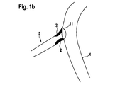
図1aは、大動脈1からの標的血管3の近位起点(開口すなわち入口部)11における大動脈入口部病変部2を示す。
FIG. 1 a shows the
図1bは、主血管4からの側枝5の開口すなわち入口部11における病変部2を示す。
FIG. 1 b shows the
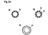
図2aは、本発明の好ましい典型的な実施形態の長手方向断面すなわち縦断面を示す図である。内側ステント20は、ギャップサイズすなわち間隙の大きさが小さい弾性変形可能な自己拡張型ステントである。すなわちこのステントは、非常に適合性の高い材料、例えばそれ自体が当分野で公知の超薄型ニチノール(Nitinol)メッシュ構造で特徴付けられる、密なメッシュ構造と超薄型のステントのストラットとを有している。このステントは、好ましくは形状記憶合金や当分野で公知のポリマー繊維を含む他の形状記憶材料で構成され、血管内等のその最終的な使用位置において、図2aに示す位置/形状をとる。図に示すように、内側ステント20の軸方向に突出する外側部分22、すなわち外側ステント30によって囲まれていない部分は広げられて、外側ステント30と外側ステント30の内側部分にある内側ステントの双方の長手方向軸に対し程度の差はあるがほぼ垂直の平面内に基本的に置かれるようにする。外側ステントは、間隙の大きさが大きい塑性変形可能なバルーン拡張型ステントであり、半径方向強度の強さに特長がある厚いステントのストラットを有する密集度の低いすなわち目の粗いメッシュ構造である。図2aの矢印aおよびbは、図2bに示す断面aおよびbの位置を示し、図2aの矢印cは、図2bのc図の見る方向を示す。c図は、図2aの右側の前端を示し、そこでは図2aの内側ステント20の外部にある部分(外側ステント30の内側ではない)が(その形状記憶特徴のために)広げられているので、2つの同軸ステント部分30および20の長手方向主軸に対し程度の差はあるがほぼ垂直にある、ほぼ円錐状(cone−like)のステント表面22を形成する。弾性変形可能な内側ステント構造の超薄型メッシュ構造の外部にある部分は、図2aに示すように(および図2bのc図の正面図において)外側ステントによって背部を保持されていないために、図2aの二重ステント構造のこの外部/近位部分は、二重ステント装置の長手方向軸に対し程度の差はあるがほぼ垂直に延びるステント層を形成するので、図1aおよび1bに示すような入口部病変部を包み込むことができる。図6aおよび6bは、開口(入口部)の解剖学上の構造の2つの例における二重ステント構造の最終的な留置の状態を示す。
FIG. 2a shows a longitudinal or longitudinal section of a preferred exemplary embodiment of the present invention. The
図3は、図2aの二重ステント構造の可能な異なる実施形態を示す図である。図3aは、遠位端に内部のステント部分を有する二重ステント構造の断面を示し、内部のステント部分を、異なる角度で広げて示す図である。この実施形態は特に分岐部において有用である。 FIG. 3 shows different possible embodiments of the dual stent structure of FIG. 2a. FIG. 3a shows a cross-section of a dual stent structure with an internal stent portion at the distal end, showing the internal stent portion unfolded at different angles. This embodiment is particularly useful at the bifurcation.
図3bは、近位端および遠位端双方において軸方向に突出しかつ図2aに関連して詳細に説明したように両端部において角度のつけられた表面を形成するワンピース型内側ステントを有する、長いワンピース型外側ステントを示す図である。この実施形態は、塞栓の危険性のある血栓の多い病変部に特に有用である。 FIG. 3b has a one-piece inner stent that projects axially at both the proximal and distal ends and forms an angled surface at both ends as described in detail in connection with FIG. 2a. FIG. 6 shows a one-piece outer stent. This embodiment is particularly useful for highly thrombus lesions at risk of embolism.
図3cは、内部部分を近位端にのみ有する、図3bに示したものと同じタイプの内側ステントを示す図であるが、外側ステントは、ステントアセンブリの長手方向の柔軟性を高めるために、個別の長さの部分を数個有していて、これは、脈管が極度に曲がりくねっている場合に特に有用である。 FIG. 3c shows an inner stent of the same type as that shown in FIG. 3b having an inner portion only at the proximal end, but the outer stent is designed to increase the longitudinal flexibility of the stent assembly. It has several parts of individual length, which is particularly useful when the vessel is extremely winding.
図3dは、上述したものと同じタイプの内側および外側ステントを有する二重ステント構造を示す図であるが、外側ステントおよび内側ステントの双方ともしっかりと接続され、逆の位置に配置されている点が異なる。ここでは、超薄型の密な弾性変形可能なメッシュステントが外側ステント構造体を形成し、足場(骨組み)のバルーン拡張型ステントが内側ステント構造体を形成する。この二重ステントデバイスは、脈管壁に対する部材の被覆率の高い、とりわけ平滑な外面を特徴とする(図7も参照)。 FIG. 3d shows a dual stent structure with inner and outer stents of the same type as described above, but both the outer and inner stents are securely connected and placed in opposite positions. Is different. Here, an ultra-thin, dense elastically deformable mesh stent forms the outer stent structure, and a balloon expandable stent of the scaffold (framework) forms the inner stent structure. This dual stent device is characterized by a particularly smooth outer surface with a high coverage of the member against the vessel wall (see also FIG. 7).
図4aは、図2aの本発明の二重ステント構造の一例を示す図であるが、ここでは、カテーテルのバルーン12の拡張によってステント構造20、30を完全に解放する前は、適用カテーテル10に配置されている点が異なる。図4aに示すように、破線で示す内側ステント20は、外側ステント30の近位端から軸方向に突出する領域にはまだ広げられていない。なぜなら、内側ステント20は、依然として21で示す箇所に束縛されてまとめられてまたは図5の実施形態にも示すような類似の配置によって押し下げられ/まとめられているからである。図5の実施形態を参照すると、この例では、磁気素子が、図2aに関連して説明したように広がる、内側ステント20の対応する部分を保持する働きをする。図4aに示すカテーテル/バルーン/二重ステント配置を、(国際公開第99/03426号パンフレット(Ischinger)に記載の公知の技術を使用して)入口部病変部において所定の位置に一旦適切に位置決めすると、バルーン12は、それ自体が周知の方法によって拡張されて、外側のバルーン拡張型(塑性変形可能な)ステント30を拡張させ、その結果内側の自己拡張型(弾性変形可能な)超薄型内側ステント20がそれに続き、突出する内側ステント20の近位部分の、21で示す箇所においてまとめられた部分が、バルーン12の拡張によって破壊、移動、もしくは引っ込められるか、またはバルーンが拡張すると縮小されるので、前述の21の箇所において突出する近位端を解放し、内側ステント20は、図2aに示しかつ図2bのcの方向から見た図に示すような位置まで広がることができる。内側ステントの突出する端部のほぼ広げられた位置を図4bにも示す。
Figure 4a is a diagram showing an example of a dual stent structure of the present invention in Figure 2a, where, prior to completely releasing the
21の箇所において示すような拘束すなわち束縛する手段または束ね部は、当分野で公知であって、通常弾性変形可能なステントの特定の(近位)領域を取り囲むシースで構成され、そのシース構造は、バルーンが拡張すると裂けるか破壊されるか、またはオペレータによって軸方向に引き出され得る。 The restraining means or bundling portion as shown at 21 is known in the art and usually consists of a sheath surrounding a particular (proximal) region of an elastically deformable stent, the sheath structure of which The balloon can be torn or broken when expanded, or pulled axially by the operator.
図4cは、本発明の二重ステント構造を標的領域へと導入するための、別の代替形態を示す図である。この実施形態では、内側の弾性変形可能なステント20の突出する近位端部は、図4aに示すような拘束された状態になっていない。その代わりに、内側ステントの、広げることが可能な近位端のための制限手段を全く有していない二重ステント構造は、ガイディングカテーテル15中を標的領域までずっと進み、二重ステント構造をガイディングカテーテル15から病変部領域へと押し出したその時点で、近位端が広がって入口部における自己ポジショニング停止の仕組みが機能する。
FIG. 4c shows another alternative for introducing the dual stent structure of the present invention into the target area. In this embodiment, the protruding proximal end of the inner elastically
図5は、非常に類似した二重ステント構成20、30のステント拡張手段としてバルーン12を備える類似の適用カテーテル10を示す。適用カテーテル/バルーンには2つのx線不透過性マーカ25、26があり、内側ステント20の遠位端の軸方向位置および外側ステントの近位端の軸方向位置を特定するので、それらの軸方向位置をX線スクリーンまたは類似の画像生成装置において明瞭に可視化させて、二重ステント構成を適所へ留置することにおいてオペレータを支援する。
FIG. 5 shows a
図5は、内側の自己拡張型ステント20の突出する部分を21で示す箇所において(図4aに示す場合とは)わずかに異なる方法で拘束すなわち束縛する配置を示す図である。これは、例えば図4bに示す位置に広げる準備ができるまで、内側ステントの突出する弾性変形可能な近位部分を保持する、例えば磁気保持システムによって達成できる。磁気保持システムを、内側ステント20の近位端におけるある磁性物質と、バルーンの近位端や図5に示す隣接するホース/カテーテル部分におけるいくつかの磁石23とで構成する。拡張/バルーン手段が活性化(作動)されたら、磁力はステント近位端部を保持するのにもはや十分ではなくなるので、この時点で弾性的な自己拡張/広がりが起こるであろう。
FIG. 5 shows an arrangement in which the protruding portion of the inner self-expanding
図6aは、図1aに示す状況において植え込まれた本発明の二重ステント構造を示す図である。 FIG. 6a shows the dual stent structure of the present invention implanted in the situation shown in FIG. 1a.
図6bは、図1bに示す状況において植え込まれた本発明の二重ステント構造を示す図である。 FIG. 6b shows the dual stent structure of the present invention implanted in the situation shown in FIG. 1b.
図6cは、図6bに示すものと類似の状況における本発明の二重ステントアセンブリを示すが、分岐部に近い主血管4から病変部にアプローチしている。この状況では、図3aまたは3bに示す二重ステントアセンブリを好ましくは使用するであろう。 FIG. 6c shows the dual stent assembly of the present invention in a situation similar to that shown in FIG. 6b, but approaching the lesion from the main vessel 4 near the bifurcation. In this situation, the dual stent assembly shown in FIG. 3a or 3b will preferably be used.
図7は、外側ステントと内側ステントが位置を交換して「逆配置」のステントを形成した、二重ステント構造の反転型配置の構成を示す図である。この構成は、ステント20、30の双方が、軸方向の重なっている部分に沿って接着剤でつけたり溶接したりまたは部分的に撚り合わせたり等によって互いにしっかりと接続されることを必要とする。この逆になった状況においても、ステント20は、密なメッシュの超薄型ステントであり、弾性変形可能で自己拡張型であるが、ここでは、二重ステント構造の外部に配置される。他方のステント30はバルーン拡張型で塑性変形可能であり、強力な足場/支持特性をもたらすが、このステントは内部に配置される。重要な点は、ここでも、薄い弾性変形可能な自己拡張性の(ここでは外側)ステントの軸方向に突出する部分が、例えば図2aまたは図7に示す位置にまで(解放時に)広がることができることである。
FIG. 7 is a diagram showing an inverted arrangement configuration of a double stent structure in which an outer stent and an inner stent exchange positions to form a “reverse arrangement” stent. This configuration requires that both
図8aの実施形態は、図2aのステントデバイスの異なるバージョンを示し、ここでは、より強く/より厚い塑性変形可能なステント30は外側にありかつバルーン拡張型ステントのステント近位端部において斜めの断面の平面を形成する。内側ステント20は、ここでも弾性変形可能な薄型メッシュステント部材で形成されている。その結果、二重ステント配置の近位端(開口)の断面の平面は、同軸二重ステント配置の部分の長手方向軸に対して非垂直すなわち斜めになっている。
The embodiment of FIG. 8a shows a different version of the stent device of FIG. 2a, where the stronger / thicker plastic
図8bは、図8aのステントの部分的な、少なくともその近位前端の斜視図である。この図に示すように、自己拡張型弾性変形可能な内側ステント20の前(近位)端部は、広がっていて、入口部病変部または側枝病変部の入口部に留置するための表面または領域を形成する。広げられた表面22は、二重ステント本体の主長手方向軸に対して幾分斜めに配置された「面」を規定する。
FIG. 8b is a perspective view of a portion of the stent of FIG. 8a, at least its proximal front end. As shown in this figure, the front (proximal) end of the self-expanding elastically deformable
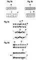
図9aは、拡張されていない状態にある管状のステント構造(40)を示す図であり、ステント構造(40)は、主に円周方向に延在する正弦曲線的エレメントで構成され、それらのエレメントは、長手方向において、主に長手方向に延在する正弦曲線的エレメントと交互に配置されて、管状ステントの壁を形成する。管状のステント(40)の半径方向の拡張によって、ステント壁(41)の構造の外部形状が修正され、その管状のステント長は、拡張後も本質的に変わらないままである。 FIG. 9a shows a tubular stent structure (40) in an unexpanded state, the stent structure (40) being composed of sinusoidal elements extending mainly in the circumferential direction, The elements are interleaved in the longitudinal direction with sinusoidal elements extending mainly in the longitudinal direction to form the wall of the tubular stent. The radial expansion of the tubular stent (40) modifies the external shape of the structure of the stent wall (41), and the tubular stent length remains essentially unchanged after expansion.
図9bは、拡張されていない状態にある管状のステント構造(44)を示す図であり、ステント構造(44)は、均一に半径方向および軸方向に延在してこの管状ステントの壁を形成する本質的に長斜方形またはダイアモンド様のセルラー構造で構成される。機械的に軸方向に拡張すると、このステントは、通常両端部から長手方向軸(45)の中心に向かって、著しく長手方向において縮小する(収縮する)(45)。 FIG. 9b shows the tubular stent structure (44) in an unexpanded state, the stent structure (44) extending radially and axially uniformly to form the wall of the tubular stent. It consists essentially of a rhomboid or diamond-like cellular structure. When mechanically expanded axially, the stent will contract (contract) significantly in the longitudinal direction (45), usually from both ends toward the center of the longitudinal axis (45).
図9cおよび9dは、それぞれ図9aおよび9bに関連して説明したような、2つの異なるステントで構成されたものとしての、二重ステントアセンブリの2つの変形形態を示す図である。 FIGS. 9c and 9d show two variations of a dual stent assembly as composed of two different stents as described in connection with FIGS. 9a and 9b, respectively.
図9cは、長手方向の縮小(長手方向に収縮)が明確に異なっている潜在能力を有する第1および第2のステント構造を使用した二重ステントアセンブリの長手方向の断面を示す図である。ステントアセンブリの拡張されていない状態では、第1のステント(外側ステント、塑性変形可能なバルーン拡張型)(44)が第2のステント(内側ステント、弾性変形可能な自己拡張型)(40)に全長にわたって重なっている。この例では、第1および第2のステントは、ステントアセンブリの長手方向軸の中央(中心)あたりに配置された接続点(48)において接続されている。ステントアセンブリの拡張後、外側ステントは、その初期の拡張されていない状態(44)と比較すると、両端部から双方向に著しく縮小(45)する一方で、拡張後の内側ステント(41)は、拡張されていない状態(40)のその初期長を本質的に維持した。 FIG. 9c shows a longitudinal cross-section of a dual stent assembly using first and second stent structures with the potential to have distinctly different longitudinal reductions (contractions in the longitudinal direction). In the unexpanded state of the stent assembly, the first stent (outer stent, plastically deformable balloon expandable) (44) becomes the second stent (inner stent, elastically deformable self-expandable) (40). It overlaps over the entire length. In this example, the first and second stents are connected at a connection point (48) located about the center (center) of the longitudinal axis of the stent assembly. After expansion of the stent assembly, the outer stent is significantly reduced (45) bi-directionally from both ends when compared to its initial unexpanded state (44), while the expanded inner stent (41) Essentially maintained its initial length in the unexpanded state (40).
図9dは、内側ステント(40)および外側ステント(44)が、二重ステントアセンブリの一方の端部あたりに配置された接続点(49)において接続されている、拡張されていない状態にある図9cの二重ステントアセンブリの他の例の長手方向の断面を示す図である。二重ステントアセンブリの拡張後、外側ステント(45)は、一方向に、すなわち二重ステントアセンブリの一方の端部分にある接続点(49)に主として向かって著しく縮小した。 FIG. 9d is an unexpanded view with the inner stent (40) and outer stent (44) connected at a connection point (49) located around one end of the dual stent assembly. FIG. 9C is a longitudinal cross section of another example of a 9c dual stent assembly. After expansion of the dual stent assembly, the outer stent (45) contracted significantly in one direction, i.e. mainly towards the connection point (49) at one end of the dual stent assembly.
図9eは、拘束を解放(=拡張)させるとその長さを増大させる可能性のある、拘束すなわち束縛状態にある内側ステント(自己拡張型)の実施形態を示す図である。この内側ステントは、主に円周方向にすなわち周囲に延在する正弦曲線的エレメント(「cese」)で構成され、それらのエレメントは、長手方向において、主に長手方向に延在する正弦曲線的エレメント(「lese」)と交互に配置されている。長手方向に延在する正弦曲線的エレメントの軸方向に延在する両端部は、その「ゼロ交差(ゼロクロス)点(zero crossing points)」において前記円周方向に延在する正弦曲線的エレメント(「cese」)に接続される。これらのゼロ交差(ゼロクロス)点は、その拡張時に長手方向においてステントのそれらの位置を実際に変更するものではない、単に「cese」の1つである。従って、円周方向に配置された正弦曲線的エレメントおよび長手方向に配置された正弦曲線的エレメントの双方が、解放後に拘束されない構成をとる(要するに:双方の正弦曲線的エレメントの伸張)ので、ステントは半径方向に自己拡張し、かつ長手方向にある程度延びる。すなわちステントの拡張の最終的な結果は、その直径およびその軸方向の長さの双方を増大させることにある。これに関連して「ゼロ交差(ゼロクロス)点」は、X軸と交差する正弦波の特定の点を指す。 FIG. 9e illustrates an embodiment of an inner stent (self-expanding) in a restraint or constrained state that may increase its length when the restraint is released (= expanded). The inner stent is comprised of sinusoidal elements ("ses") that extend primarily circumferentially or circumferentially, the elements being sinusoidally extending in the longitudinal direction, primarily longitudinally. Alternating with elements (“less”). Both axially extending ends of the sinusoidal element extending in the longitudinal direction are connected to the circumferentially extending sinusoidal element (“zero crossing points”). ses ")). These zero-crossing points (zero-crossing points) are just one of “ceses” that do not actually change their position in the longitudinal direction when expanded. Therefore, since both the circumferentially arranged sinusoidal element and the longitudinally arranged sinusoidal element are configured to be unconstrained after release (in short: stretching both sinusoidal elements), the stent Is self-expanding in the radial direction and extends to some extent in the longitudinal direction. That is, the net result of stent expansion is to increase both its diameter and its axial length. In this context, a “zero crossing point” refers to a specific point of a sine wave that intersects the X axis.
Claims (17)
物理的特性が著しく異なる第1および第2のステント(30;20)を有し、該第1および第2のステントは同軸に配置され、かつステントの長さの少なくとも1つの選択部分において重なっており、前記第2のステント(20)は、前記第1のステント(30)の少なくとも1つの端部(近位および/または遠位)から軸方向に突出し、前記ステントアセンブリの少なくとも1つの突出する端部は、主として形状記憶材料の、自己拡張性弾性変形可能なステント部材で構成されていて、前記第2のステントの突出する端部のすそ広がりの端部(22)を形成するとともに、前記ステントアセンブリの残りの部分の長手方向軸に垂直または斜めに延びる面に基本的に存在するステント部分を規定している、ステントアセンブリ。 An expandable activatable tube having a proximal end and a distal end, and a first longitudinal portion having at least a first physical property and a second longitudinal portion having at least a second physical property In the stent assembly of
The first and second stent preparative physical properties that differ significantly; have (30 20), said first and second stents are coaxially arranged, and at least one selected portion of the length of the stent Overlapping, the second stent (20) projects axially from at least one end (proximal and / or distal) of the first stent (30), and at least one of the stent assemblies The projecting end is composed of a self-expanding elastically deformable stent member, mainly of shape memory material, and forms a flared end (22) of the projecting end of the second stent. A stent assembly that essentially defines a stent portion that lies in a plane extending perpendicularly or obliquely to the longitudinal axis of the remaining portion of the stent assembly.
物理的特性が著しく異なる第1および第2のステント(30;20)を有し、該第1および第2のステントは同軸に配置され、かつステントの長さの少なくとも1つの選択部分において重なっており、前記第1および第2のステントの前記重なりにより生ずる、拡張前には本質的に同じ長さの内側ステント(40;41)および外側ステント(44;45)が、これら2つのステントの前記軸方向の長さに沿った1つの円周方向のライン(48;49)の多数の点において互いに物理的に接続され、それにより少なくとも1つのステントが、前記ステントアセンブリ拡張後に軸方向に異なる長さを呈する(図9cおよび9d)、ステントアセンブリ。 An expandable activatable tube having a proximal end and a distal end, and a first longitudinal portion having at least a first physical property and a second longitudinal portion having at least a second physical property In the stent assembly of
First and second stent preparative physical properties that differ significantly; have (30 20), said first and second stents are coaxially disposed, or Tsusu least one selected length of the tent overlaps in part, the first and caused by the overlap of the second stent, essentially the same length of the inner side stent before expansion (40; 41) and outer side stent (44; 45) but these two stents of said axial one circumferential direction along the length of the line; in a number of points (48 49) are physically connected to each other, whereby at least one stent, said stent A stent assembly that exhibits different axial lengths after assembly expansion (FIGS. 9c and 9d).
Applications Claiming Priority (2)
| Application Number | Priority Date | Filing Date | Title |
|---|---|---|---|
| EP05027410A EP1797843A1 (en) | 2005-12-14 | 2005-12-14 | Lesion specific stents, also for ostial lesions, and methods of application |
| PCT/EP2006/011918 WO2007068430A1 (en) | 2005-12-14 | 2006-12-11 | Lesion specific stents, also for ostial lesions, and methods of application |
Publications (2)
| Publication Number | Publication Date |
|---|---|
| JP2009519061A JP2009519061A (en) | 2009-05-14 |
| JP2009519061A5 true JP2009519061A5 (en) | 2010-01-28 |
Family
ID=35645720
Family Applications (1)
| Application Number | Title | Priority Date | Filing Date |
|---|---|---|---|
| JP2008544849A Pending JP2009519061A (en) | 2005-12-14 | 2006-12-11 | A lesion-specific stent that is also used for an entrance lesion and an application method |
Country Status (4)
| Country | Link |
|---|---|
| US (1) | US20090005857A1 (en) |
| EP (2) | EP1797843A1 (en) |
| JP (1) | JP2009519061A (en) |
| WO (1) | WO2007068430A1 (en) |
Families Citing this family (11)
| Publication number | Priority date | Publication date | Assignee | Title |
|---|---|---|---|---|
| US8308797B2 (en) | 2002-01-04 | 2012-11-13 | Colibri Heart Valve, LLC | Percutaneously implantable replacement heart valve device and method of making same |
| CN102307542B (en) * | 2008-11-24 | 2016-05-11 | 血管移植技术有限公司 | Outside support |
| CA2806544C (en) * | 2010-06-28 | 2016-08-23 | Colibri Heart Valve Llc | Method and apparatus for the endoluminal delivery of intravascular devices |
| SG191008A1 (en) | 2010-12-14 | 2013-07-31 | Colibri Heart Valve Llc | Percutaneously deliverable heart valve including folded membrane cusps with integral leaflets |
| JP5767494B2 (en) * | 2011-03-28 | 2015-08-19 | 株式会社カネカ | Covered stent, stent delivery catheter, and method for manufacturing covered stent |
| US10052218B2 (en) | 2011-04-18 | 2018-08-21 | Vascular Graft Solutions Ltd. | Devices and methods for deploying implantable sleeves over blood vessels |
| WO2013138789A1 (en) | 2012-03-16 | 2013-09-19 | Microvention, Inc. | Stent and stent delivery device |
| EP2988705A4 (en) * | 2013-04-23 | 2016-11-02 | Medical Ingenuities Llc | Interconnection between selectively-expandable and self-expandable sections of an ostial stent |
| WO2019051476A1 (en) | 2017-09-11 | 2019-03-14 | Incubar, LLC | Conduit vascular implant sealing device for reducing endoleak |
| DE102018105925A1 (en) * | 2018-03-14 | 2019-09-19 | Malte Neuss | double stent |
| US11628052B2 (en) * | 2020-05-13 | 2023-04-18 | Jt Godfrey, Llc | Device for use with body tissue sphincters |
Family Cites Families (19)
| Publication number | Priority date | Publication date | Assignee | Title |
|---|---|---|---|---|
| US5064435A (en) * | 1990-06-28 | 1991-11-12 | Schneider (Usa) Inc. | Self-expanding prosthesis having stable axial length |
| US5366504A (en) * | 1992-05-20 | 1994-11-22 | Boston Scientific Corporation | Tubular medical prosthesis |
| US5360440A (en) * | 1992-03-09 | 1994-11-01 | Boston Scientific Corporation | In situ apparatus for generating an electrical current in a biological environment |
| US5607444A (en) * | 1993-12-02 | 1997-03-04 | Advanced Cardiovascular Systems, Inc. | Ostial stent for bifurcations |
| US6096071A (en) * | 1998-03-26 | 2000-08-01 | Yadav; Jay S. | Ostial stent |
| US5980565A (en) * | 1997-10-20 | 1999-11-09 | Iowa-India Investments Company Limited | Sandwich stent |
| US6168621B1 (en) * | 1998-05-29 | 2001-01-02 | Scimed Life Systems, Inc. | Balloon expandable stent with a self-expanding portion |
| US6368345B1 (en) * | 1998-09-30 | 2002-04-09 | Edwards Lifesciences Corporation | Methods and apparatus for intraluminal placement of a bifurcated intraluminal garafat |
| US6245100B1 (en) * | 2000-02-01 | 2001-06-12 | Cordis Corporation | Method for making a self-expanding stent-graft |
| US6602280B2 (en) * | 2000-02-02 | 2003-08-05 | Trivascular, Inc. | Delivery system and method for expandable intracorporeal device |
| US20010044650A1 (en) * | 2001-01-12 | 2001-11-22 | Simso Eric J. | Stent for in-stent restenosis |
| US20030083734A1 (en) * | 2001-10-25 | 2003-05-01 | Curative Ag | Stent |
| US6939368B2 (en) * | 2002-01-17 | 2005-09-06 | Scimed Life Systems, Inc. | Delivery system for self expanding stents for use in bifurcated vessels |
| ATE425720T1 (en) * | 2002-01-28 | 2009-04-15 | Orbusneich Medical Inc | EXPANDED OSTIUM ENDPROSTHESIS AND DELIVERY SYSTEM |
| US7172622B2 (en) * | 2002-10-30 | 2007-02-06 | Boston Scientific Scimed, Inc. | Medical devices including a magnetically activatable body or portion for treatment |
| US7105015B2 (en) * | 2003-06-17 | 2006-09-12 | Medtronic Vascular, Inc. | Method and system for treating an ostium of a side-branch vessel |
| US20050203606A1 (en) * | 2004-03-09 | 2005-09-15 | Vancamp Daniel H. | Stent system for preventing restenosis |
| EP1765221A1 (en) * | 2004-06-16 | 2007-03-28 | Cook Incorporated | Thoracic deployment device and stent graft |
| US7455688B2 (en) * | 2004-11-12 | 2008-11-25 | Con Interventional Systems, Inc. | Ostial stent |
-
2005
- 2005-12-14 EP EP05027410A patent/EP1797843A1/en not_active Withdrawn
-
2006
- 2006-12-11 US US12/097,073 patent/US20090005857A1/en not_active Abandoned
- 2006-12-11 EP EP06829505A patent/EP1968488A1/en not_active Withdrawn
- 2006-12-11 WO PCT/EP2006/011918 patent/WO2007068430A1/en active Application Filing
- 2006-12-11 JP JP2008544849A patent/JP2009519061A/en active Pending
Similar Documents
| Publication | Publication Date | Title |
|---|---|---|
| JP2009519061A5 (en) | ||
| JP2009519061A (en) | A lesion-specific stent that is also used for an entrance lesion and an application method | |
| US20200155331A1 (en) | Vascular implant | |
| US9757262B2 (en) | Stent graft | |
| US7238197B2 (en) | Endoprosthesis deployment system for treating vascular bifurcations | |
| JP4097897B2 (en) | Extensible stent device | |
| JP4309407B2 (en) | Bifurcated endoprosthesis | |
| KR101837113B1 (en) | Endoluminal device | |
| US20030083734A1 (en) | Stent | |
| US20050033406A1 (en) | Branch vessel stent and graft | |
| EP3046508B1 (en) | System for deploying a luminal prosthesis over a carina | |
| JP2007517603A (en) | Oral stent system | |
| JP2000202032A (en) | Expandable intraluminal endoprosthesis | |
| JP2006513010A5 (en) | ||
| WO2004103451A1 (en) | Temporarily indwelled stent and stent graft | |
| JP2008229338A (en) | Vascular fluoroscopic marker | |
| EP1117458A1 (en) | Guidewire capture device | |
| EP1887994A2 (en) | Mechanically actuated stents and apparatus and methods for delivering them | |
| TW201414514A (en) | Method and apparatus for endovascular therapy of aortic pathology | |
| US20110054438A1 (en) | Stent delivery at a bifurcation, systems and methods | |
| CN115038408A (en) | System and method for introducing a stent graft through a blood vessel located above the diaphragm | |
| JP6943983B2 (en) | Bifurcated internal prosthesis with tail for controlled bifurcation deployment | |
| AU757761B2 (en) | Guidewire capture device |