JP2009516562A - Apparatus, method and system for operating an in-vivo imaging device - Google Patents
Apparatus, method and system for operating an in-vivo imaging device Download PDFInfo
- Publication number
- JP2009516562A JP2009516562A JP2008541909A JP2008541909A JP2009516562A JP 2009516562 A JP2009516562 A JP 2009516562A JP 2008541909 A JP2008541909 A JP 2008541909A JP 2008541909 A JP2008541909 A JP 2008541909A JP 2009516562 A JP2009516562 A JP 2009516562A
- Authority
- JP
- Japan
- Prior art keywords
- coil
- switch
- radio frequency
- power
- frequency radiation
- Prior art date
- Legal status (The legal status is an assumption and is not a legal conclusion. Google has not performed a legal analysis and makes no representation as to the accuracy of the status listed.)
- Withdrawn
Links
Images


Classifications
-
- A—HUMAN NECESSITIES
- A61—MEDICAL OR VETERINARY SCIENCE; HYGIENE
- A61B—DIAGNOSIS; SURGERY; IDENTIFICATION
- A61B1/00—Instruments for performing medical examinations of the interior of cavities or tubes of the body by visual or photographical inspection, e.g. endoscopes; Illuminating arrangements therefor
- A61B1/04—Instruments for performing medical examinations of the interior of cavities or tubes of the body by visual or photographical inspection, e.g. endoscopes; Illuminating arrangements therefor combined with photographic or television appliances
- A61B1/041—Capsule endoscopes for imaging
-
- A—HUMAN NECESSITIES
- A61—MEDICAL OR VETERINARY SCIENCE; HYGIENE
- A61B—DIAGNOSIS; SURGERY; IDENTIFICATION
- A61B1/00—Instruments for performing medical examinations of the interior of cavities or tubes of the body by visual or photographical inspection, e.g. endoscopes; Illuminating arrangements therefor
- A61B1/00002—Operational features of endoscopes
- A61B1/00011—Operational features of endoscopes characterised by signal transmission
- A61B1/00016—Operational features of endoscopes characterised by signal transmission using wireless means
-
- A—HUMAN NECESSITIES
- A61—MEDICAL OR VETERINARY SCIENCE; HYGIENE
- A61B—DIAGNOSIS; SURGERY; IDENTIFICATION
- A61B1/00—Instruments for performing medical examinations of the interior of cavities or tubes of the body by visual or photographical inspection, e.g. endoscopes; Illuminating arrangements therefor
- A61B1/00002—Operational features of endoscopes
- A61B1/00025—Operational features of endoscopes characterised by power management
- A61B1/00036—Means for power saving, e.g. sleeping mode
-
- A—HUMAN NECESSITIES
- A61—MEDICAL OR VETERINARY SCIENCE; HYGIENE
- A61B—DIAGNOSIS; SURGERY; IDENTIFICATION
- A61B1/00—Instruments for performing medical examinations of the interior of cavities or tubes of the body by visual or photographical inspection, e.g. endoscopes; Illuminating arrangements therefor
- A61B1/04—Instruments for performing medical examinations of the interior of cavities or tubes of the body by visual or photographical inspection, e.g. endoscopes; Illuminating arrangements therefor combined with photographic or television appliances
- A61B1/045—Control thereof
-
- A—HUMAN NECESSITIES
- A61—MEDICAL OR VETERINARY SCIENCE; HYGIENE
- A61B—DIAGNOSIS; SURGERY; IDENTIFICATION
- A61B2560/00—Constructional details of operational features of apparatus; Accessories for medical measuring apparatus
- A61B2560/02—Operational features
- A61B2560/0204—Operational features of power management
- A61B2560/0209—Operational features of power management adapted for power saving
Abstract
最初に休止状態にある撮像装置がRF放射線に曝らされることで摂取前に作動されるよう、RF放射線信号を用いる摂取可能な撮像装置を作動する装置、システム、及び、方法。装置は、切り換えられると装置の一つ以上の電気的構成要素への給電を円滑にするRFスイッチを含む。RFスイッチは、摂取可能な撮像装置を停止するためにも機能する。An apparatus, system, and method for operating an ingestible imaging device that uses an RF radiation signal such that the imaging device that is initially in a dormant state is activated prior to ingestion upon exposure to RF radiation. The device includes an RF switch that, when switched, facilitates powering one or more electrical components of the device. The RF switch also functions to stop an ingestible imaging device.
Description
本発明は、摂取可能な撮像装置に係り、特に、無線周波数の放射線を用いて摂取可能な撮像装置を作動する装置に関する。 The present invention relates to an ingestible imaging device, and more particularly to an apparatus for operating an ingestible imaging device using radio frequency radiation.
摂取可能な撮像カプセルのような生体内検知装置は、使用において電力がある限られた期間持ちこたえることができる電池などの自律型電源を備える。電力を節約するためには、装置が摂取されるか飲み込まれる直前に装置をオンにすることが好ましい。典型的には、生体内装置の耐久性や水密性を保証するために、電池や全ての他の構成要素が製造中装置内に密閉されている。このような装置は、密閉後に装置を動作させ得る手動のまたは外部からアクセス可能なスイッチあるいはメカニズムを収容していない。品質管理基準では、各装置が使用前に検査されなくてはならないため、生体内での動作の前に装置が検査目的で可能性として数回にわたって作動され、停止される必要がある。 An in-vivo sensing device such as an ingestible imaging capsule includes an autonomous power source such as a battery that can be used for a limited period of time during use. In order to save power, it is preferable to turn on the device just before it is ingested or swallowed. Typically, batteries and all other components are sealed within the device during manufacture to ensure the durability and water tightness of the in vivo device. Such devices do not contain manually or externally accessible switches or mechanisms that can operate the device after sealing. According to quality control standards, each device must be tested before use, so the device must be activated and shut down as many times as possible for testing purposes before in vivo operation.
公知の生体内撮像装置は、使用前に装置を作動させるためのリード・スイッチを備えてもよい。リード・スイッチは、電磁(EM)場に敏感であり、所定の強さのEM場に曝されると閉じるか開く。あるケースでは、公知のリード・スイッチは、例えば、製造業者から消費者への撮像装置の運搬中および取り扱い中の機械的ショックに敏感である。他のケースでは、リード・スイッチは、周囲環境からのEM干渉に敏感である。更に別のケースでは、リード・スイッチはEM場に曝されると時として解消できない公知のスタッキング効果を受ける。 Known in-vivo imaging devices may include a reed switch for operating the device prior to use. Reed switches are sensitive to electromagnetic (EM) fields and close or open when exposed to a predetermined strength EM field. In some cases, known reed switches are sensitive to mechanical shocks, for example, during transport and handling of the imaging device from the manufacturer to the consumer. In other cases, the reed switch is sensitive to EM interference from the surrounding environment. In yet another case, the reed switch experiences a known stacking effect that sometimes cannot be eliminated when exposed to an EM field.
本発明の実施形態によると、無線周波数(RF)の放射線により遠隔的に摂取可能な撮像装置を作動する装置、方法、および、システムが提供される。一例では、この作動は、機械的に固定の構成要素等の電気的な構成要素を用いて円滑化され得る。本発明の一実施形態によると、摂取可能な装置内に設けられるRF動作スイッチは、所定のRF放射線信号に曝されると、装置の電力状態を変更する等、動作状態を変更する。RF動作スイッチは、装置内の一つ以上の電気的構成要素に電池電力等の電力を供給することで装置を休止状態から活性化させる。作動状態では、摂取可能な撮像装置は、生体内から外部受信装置に無線で画像データや他のデータを送信し、および/または、制御データ等のデータを受信してもよい。別の実施例では、RF動作スイッチは、装置を停止して装置を休止状態に戻してもよい。一実施例では、必要に応じて作動と停止が繰り返し実行される。本発明の一実施形態によると、動作状態の変更は、RF放射線の終了後も維持され得る。装置の作動と停止は、装置を摂取する前に行われる。 In accordance with embodiments of the present invention, an apparatus, method, and system for operating an imaging device that can be ingested remotely by radio frequency (RF) radiation are provided. In one example, this operation can be facilitated using electrical components such as mechanically fixed components. According to one embodiment of the present invention, an RF operation switch provided in an ingestible device changes its operating state when exposed to a predetermined RF radiation signal, such as changing the power state of the device. The RF operation switch activates the device from a dormant state by supplying power, such as battery power, to one or more electrical components within the device. In an operating state, an ingestible imaging device may wirelessly transmit image data and other data and / or receive data such as control data from within the living body to an external receiving device. In another example, the RF operational switch may stop the device and return the device to a dormant state. In one embodiment, activation and deactivation are repeated as necessary. According to one embodiment of the present invention, the change in operating state can be maintained after termination of RF radiation. The device is turned on and off before the device is ingested.
本発明は、図面を参照する以下の詳細な説明からより完全に理解され、認識されるであろう。
例示を簡略化し明確化するために、図中の構成は必ずしも正確にまたは縮尺通りに描かれていないことは理解されるであろう。例えば、幾つかの構成の寸法は明確化のために他の構成に対して誇張され、あるいは、幾つかの物理的な構成要素は一つの機能ブロックまたは構成内に含まれていてもよい。更に、適当な場合には、同じ参照番号が対応するまたは同様の構成を示すために図中繰り返し使用される。
The present invention will be understood and appreciated more fully from the following detailed description, taken in conjunction with the drawings in which:
It will be understood that the structures in the figures are not necessarily drawn to scale or to scale for clarity and clarity of illustration. For example, the dimensions of some configurations may be exaggerated relative to other configurations for clarity, or some physical components may be included within a single functional block or configuration. Further, where appropriate, the same reference numerals are used repeatedly in the figures to indicate corresponding or similar configurations.
本発明の様々な態様を以下に説明する。説明目的のため、本発明の完全な理解を提供するために特定の構成および詳細を説明する。しかしながら、当業者には、本発明が本願記載の特定の詳細を有することなく実行されてもよいことは理解されるであろう。更に、本発明を不明瞭にしないために周知の特徴は省略されているか、あるいは、簡略化されている。 Various aspects of the invention are described below. For purposes of explanation, specific configurations and details are set forth in order to provide a thorough understanding of the present invention. However, it will be understood by one skilled in the art that the present invention may be practiced without the specific details described herein. Furthermore, well-known features have been omitted or simplified in order not to obscure the present invention.
本発明の実施形態による遠隔RF放射線源を備える生体内撮像システムの簡略化された概念図を示す図1を参照する。装置100は、生体内でデータを収集する自律型生体内センサ、例えば、生体内撮像装置である。RF放射線源174は、装置100を生体内に挿入する前に休止状態から装置100を遠隔的に作動する。作動されると、データは生体内で収集され、一つ以上の受信アンテナ15を備えるRF受信器等の外部受信器12に送信される。幾つかの実施形態では、受信器12は、受信データを記録し記憶する記録部と記憶部を含んでもよく、処理機能を備えてもよい。装置100によって捕捉され、受信器12によって受信されるデータは、処理、分析、および、表示部18での表示のためにワークステーション14にダウンロードされてもよい。本発明の一実施形態では、受信器12とワークステーション14とは単一のユニットに一体化されてもよく、例えば、単一の携帯ユニットに一体化されてもよい。他の実施形態では、受信器12は装置100に信号を送信することができ、且つ、受信することができる。本発明の更に別の実施形態では、受信器12は表示機能を備えてもよく、例えば、受信器12はオンライン・ビューアを備えてもよい。
Reference is made to FIG. 1 showing a simplified conceptual diagram of an in-vivo imaging system with a remote RF radiation source according to an embodiment of the present invention. The
装置100は、外側被覆部または筐体110内に本発明の実施形態に従って構成され動作される撮像ユニット112等の検知装置を含んでもよい。筐体110は、球形、卵形、または、全ての他の好適な形状であり、部分的に変形可能でもよい。撮像ユニット112は、電荷結合素子(CCD)、相補型金属酸化膜半導体(CMOS)イメージャ、別の好適な固体イメージャ、または、他のイメージャである、あるいは、それを含む少なくとも一つのイメージャ116を典型的には備える。更に、撮像ユニット112は、レンズ122、レンズ・ホルダ120、および、イメージャ116によって撮像されるべき領域を照明する一つ以上の(例えば、一対の、一環の等)発光ダイオード(LED)等の照明源118を含んでもよい。イメージャ116、照明源118、および、他の構成要素について他の位置が使用されてもよく、他の形状の筐体110が使用されてもよい。
The
装置100は、一つ以上の電力ユニット126、RF送信器等の送信器127、および、制御データを受信する等、受信データを送信および/または受信する一つ以上のアンテナ128を含むおよび/または備える。電力ユニット126は、一つ以上の電池および/または他の好適な電力源を含んでもよい。別の実施例では、電力ユニット126は、外部源から電力を受ける電力誘導ユニットを含んでもよい。一実施例では、送信器127は、制御機能を備えてもよく、例えば、送信器127は装置100の各種動作を制御する制御器でもよく、あるいは、それを含んでもよいが、制御機能または一つ以上の制御態様は回路基板または装置100に含まれる他の回路等の別の構成要素に与えられてもよい。送信器127は、特定用途向け集積回路(ASIC)に典型的には含まれるが、他の構成でもよい。装置100は、命令を含むか命令を処理する処理ユニットを送信器127とは別に備える。送信器127は、送信器127、イメージャ116、および、照明源118の給電等、装置100の作動を制御し得る機械的に固定のRF動作スイッチ127aの構成要素を少なくとも部分的に含んでもよい。他の構成要素は、RF動作スイッチ127aによって直接的にあるいは間接的に作動され得る。RFスイッチ127aは、要求に応じて、装置100または装置100の構成要素を作動するおよび/または停止するおよび/または制御するための動作スイッチとして機能する。一実施例では、要求があった場合に送信器を円滑に活性化させるよう装置100の休止状態中に装置100の一つ以上の低電力構成要素が給電されてもよい。一実施形態によると、電源126を消耗させないよう使用前は装置100を休止状態で維持することが望ましい。休止状態中、装置100は最小限の電力を消費する。
The
装置100は、飲み込むか摂取することで生体内に入れられる。装置100は、生体内撮像のために体内の内腔に入れられ、身体内のある位置に固定されるか、消化管あるいは他の体内の内腔中を移動する。装置100は、本願と共通の出願人にそれぞれ譲渡され、且つ、それぞれ本願で参照として完全に組み込まれる、イダン(Iddan)外による米国特許第5604531号明細書、イダン(Iddan)外による米国特許第7009634号明細書、および/または、2002年8月15日に発行された「体内の内腔を広視野撮像するシステムおよび方法」なる名称の米国特許出願公開第2002/0109774号明細書に開示される撮像装置の構成要素を含み同様に動作する。更に、米国特許第5604531号明細書、米国特許第7009634号明細書、および/または米国特許出願公開第2002/0109774号明細書の実施形態等に記載されるような受信、処理、および、検討システムが使用されてもよいが、他の好適な受信、処理、および、検討システムが使用されてもよい。
The
一実施形態では、装置100の構成要素は筐体110内に密閉され、例えば、水密に密閉され、本体あるいはシェルは一つ以上の部分よりなる。例えば、イメージャ116、照明源、電源126、送信器127、および、回路基板124が装置本体内に密閉されるか設けられてもよい。
In one embodiment, the components of the
装置100は、例えば、電力を受けるか、または情報を送信するために装置の外部に配線またはケーブルを必要としないカプセルまたは他のユニットでもよい。電力は内部電池によって供給されてもよい。他の実施形態は他の構成や機能を有してもよい。構成要素は、多数の部位またはユニットにわたって分配されてもよい。制御情報は、外部源から受信され得る。装置100は、最初休止状態にあり、所定のレベルおよび/またはパターンのRF放射線に曝らされることで摂取前に作動され、かつ/あるいは活性化させられる。RF放射線は、アンテナ128でエネルギーを誘導し、RFスイッチ127aに信号を送信することで装置100の動作を作動する。別の実施形態では、RFスイッチ127aは、装置100の動作を停止するように機能してもよい。外部RF放射線源174は、装置100を動作させる、オンにするか、または、活性化させるに必要なRF放射線信号を生成するために使用されてもよい。本発明の一実施形態によると、生成された信号は所定のパターンを有する。例えば、第1の所定のパターンは装置100を活性化させることをRFスイッチ127aに指示し、第2の所定のパターンは装置100を休止状態に戻すことをRFスイッチ127aに指示する。装置100を作動するおよび停止する回数は無制限である。装置の電力状態等の動作状態または機能状態を制御するために他の信号が実行されてもよい。
The
一実施形態では、電気的構成要素が密閉されているか、さもなければ、筐体またはシェル内に収容されているため、装置あるいは装置の構成要素は、装置外で生成されたRF信号等の遠隔信号を用いて作動される、オンにされるか、あるいは、停止されるかもしくはオフにされてもよい。 In one embodiment, the device or device component may be remote, such as an RF signal generated outside the device, because the electrical component is sealed or otherwise contained within a housing or shell. It may be activated using a signal, turned on, or stopped or turned off.
本発明の実施形態による、装置100を摂取する前および/または装置100を生体内に挿入する前に装置100を作動するおよび/または停止するようRF信号を生成するために使用される外部RF放射線源174の簡略図を示す図2を参照する。一実施例では、RF放射線源174は、装置100を休止状態から活性化させるためにRF放射線信号を生成する。本発明の一実施形態によると、電気的に給電されるコイル176は、コイル176に電流が流れるとRF放射線信号を生成する。電流は、ユニットの制御部を作動すること、および/またはボタンもしくはダイアル・スイッチ等のスイッチ178を動作することで流れ始める。他の制御方法が使用されてもよい。装置100は、作動するためにRF放射線源174の作動されたコイル176内に挿入されてもよく、例えば、装置100の内部コイル128がコイル176と略平行にまたは同一線上になるよう挿入される。作動されると、装置100内のRFスイッチ127aは、装置を作動後に動作上作動状態に維持するか、RFスイッチ127aによってRF放射線パターン等の追加的なおよび/または代替的なRF放射線信号が受信されるまで該状態を維持してもよい。例えば、RFスイッチ127aを介して装置100の一つ以上の電気的構成要素に供給される電力は、無線周波数の放射終了後に供給されてもよい。装置100は、作動された後、生体内に挿入され、一つ以上の生体内の管腔を通じて生体内データを捕捉し送信する。
External RF radiation used to generate an RF signal to activate and / or deactivate
一実施形態では、コイル176内に挿入された装置100の動作状態を検知するためにコイル176が追加的に使用されてもよい。例えば、コイル176またはRF放射線源174の他の構成要素が、装置100の動作状態を示す信号等、装置100によって送信される信号を捕捉する受信アンテナとして機能してもよい。装置100の動作状態等を示すよう他の信号が捕捉されて処理されてもよい。状態LED180は、装置100の検知された動作状態を示す。例えば、装置100が動作上作動状態にある場合には緑色に点灯する。装置100が動作上休止状態にある場合には赤色に点灯する。他の好適な表示が行われてもよい。制御部178は、動作上休止状態から動作上作動状態、あるいはその逆に装置を切り換えるために使用されてもよい。
In one embodiment, the
本発明の一実施形態では、RF放射線源174は、独立型ユニット、携帯型、あるいは、机上に置くに好適な形態でもよい。本発明の他の実施形態では、RF放射線源174は受信器12および/またはワークステーション14と一体でもよく、あるいは、他の好適な形態でもよい。他の実施例では、RF放射線源174は、例えば、装置100のブリスター包装等、装置100の包装と一体でもよく、このとき、ブリスターが開けられるとRF放射線源174の動作が開始される。他の構成も可能である。幾つかの実施形態では、ユニット174は電池等の独立か、または携帯型の電源を含んでもよい。幾つかの実施形態では、ユニット174は、装置がオンにされたか、あるいは作動されたことを示すためにブザーまたは呼び出し音等の信号を発してもよい。幾つかの実施形態では、ユニット174は、作動された装置の機能を評価して、作動された装置が正常におよび/または所望の通りに動作しているか否かを判断してもよい。例えば、ユニット174は、摂取可能なセンサの内部にある電池または電源が動作しているか否かを評価してもよい。他の特徴または構成要素がユニット174内に含まれてもよく、他の構成も可能である。装置100に無線周波数の放射線を生成する他の方法も可能である。動作している装置100は、トランスフォーマとして機能して、RF範囲等のエネルギーを装置100のアンテナ128に伝達することで、RFスイッチ127aを作動および/または停止してもよい。
In one embodiment of the invention, the
本発明の実施形態によるRF放射線源174の簡略化された回路図を示す図3を参照する。RF放射線源174は、RF放射線源174を給電する電池等のDC電源といった電源302と、ユニット174の動作を制御する制御部178とを備える。一実施例では、制御部178は内部スイッチ378を制御し得る。別の実施例では、制御部178とスイッチ378は同一でもよく、例えば、単一の構成要素でもよい。本発明の一実施形態によると、RF放射線源174は、典型的にはRFIDタグを動作するために使用される周波数で動作してもよい。典型的な周波数は13.56MHz、27.12MHz、865MHz、および、2.45GHzを含む。他のRFID周波数または他の好適な周波数が使用されてもよい。発振器311は、給電されると、コイル176およびコンデンサ307を含む並列共振回路310に所望の電流を生成する。並列共振回路310は、共振回路309(図4)と同じ共振周波数となるよう調整される。共振回路310は、品質(Q)係数だけ発振器311からの電流を増幅する。一実施例では、Q係数は10乃至100の範囲にある。他の好適な範囲が使用されてもよい。
Reference is made to FIG. 3 showing a simplified circuit diagram of an
他の実施形態では、並列共振回路310は直列共振回路310に置き換えられてもよい。ユニット174の回路はトランスフォーマと同様でもよく、コイル176は、装置100内のアンテナ128等の二次コイルに電圧を誘導する一次コイルでもよい。装置100を動作上作動するようRF放射線信号を生成するために他の好適な回路が使用されてもよい。本発明の一実施形態によると、コイル176とアンテナ128は、アンテナ176からアンテナ178に最大および/または十分な量の電圧および/または電流が誘導されるような位置に互いに対して配置されてもよい。本発明の一実施形態によると、アンテナ176および128はコイルでもよく、所望の相対位置では、アンテナ176および128が互いに対して並列および/または同一線上になる。
In other embodiments, the parallel
幾つかの実施形態では、装置100がコイル176内に実質的に配置されると、コイル内で生成されたRF放射線が、装置100内のRFスイッチ127aを作動し得るレベルまで装置100内のアンテナ128で電圧を誘導する。
In some embodiments, when the
本発明の実施形態による生体内装置100内のRFスイッチの典型的な回路図を示す図4を参照する。RFエネルギーを受信し、スイッチあるいは制御部として機能する他の公的なスイッチまたは装置が使用されてもよい。コイル176によって放射されるエネルギーは、装置100のアンテナ128で電圧を誘導して、RFスイッチ127aに装置の電力状態を変更させる。本発明の一実施形態によると、AC−DC変換器等の整流回路405は、ダイオード・ブリッジやコンデンサ等、受信した信号を整流するよう実行される。閾値ブロック410は、所定の閾値を超える信号だけが装置100の作動を開始するよう閾値化を行ってもよい。例えば、所定の閾値を超える信号は、制御部420に対して、スイッチ430を作動して電源126で給電し、かつ/あるいは送信器127を活性化させるよう指示してもよい。他の構成要素は、RFスイッチ127aで給電され得る。一実施例では、1ボルトの振幅の信号が閾値ブロック410を通過するに必要である。他の振幅レベルが使用されてもよい。制御部420、整流回路405、閾値ブロック410、または、他の構成要素、あるいはその機能は、送信器127等に組み込まれてもよい。
Reference is made to FIG. 4 showing an exemplary circuit diagram of an RF switch in the in-
本発明の一実施形態によると、装置174によって生成されるRF信号は、1乃至100マイクロWB/m2の範囲の電磁場を生成し得る。他の範囲の電磁場が生成されてもよい。本発明の他の実施形態では、装置10の誤作動および/または停止を回避するために、所定数のパルスまたは何らかのパターンの信号が、装置が動作状態を変更する前に閾値ブロック410を通過する必要がある。本発明の一実施形態では、制御部420はタイマ、カウンタ、および、他の構成要素または回路を含み得る。タイマは、閾値410を通過し得るパルス間の間隔を測定するために使用される。カウンタは、パルス数を計数するために使用される。例えば、装置100を作動するためには、4つのパルスが閾値410を通過する必要があり、閾値410を通過する一対のパルス間の時間間隔が5乃至10ミリ秒の時間範囲内であることが必要である。他のパルス数が使用されてもよい。本発明の一実施形態によると、最初のパルスが閾値410を通過して初めて一つ以上のタイマが作動されるため、休止状態中に電力が節約される。作動信号を検出する他の方法が実行されてもよい。
According to one embodiment of the present invention, the RF signal generated by
装置100の休止状態中、制御部420は電源126によって給電され、装置100の動作上の作動が実現される。制御部420の電力消費は、休止状態中は例えば、100ナノアンプ乃至200ナノアンプ等、50乃至200ナノアンプと最小であるため、装置100の電源126が消耗されない。一実施例では、制御部420は電力消費量を容易に最小化するために休止状態中は部分的にだけ作動されてもよい。
During the resting state of the
本発明の別の実施形態では、RFスイッチは、装置100を作動する際に使用されるのと同様にして装置100を停止するトグル・スイッチでもよい。例えば、最初のパルスおよび/またはパルスの組が装置100を作動し、後続するパルスまたはパルスの組が装置100を停止する。別の実施形態では、第1のパターンのパルスが装置100を作動するために使用され、かつ/あるいは要求され、第2のパターンのパルスが装置100を停止するために使用され、かつ/あるいは要求される。装置100の電力状態を変更させる、例えば、装置100を作動し、かつ/あるいは停止する他の方法が実行されてもよい。
In another embodiment of the present invention, the RF switch may be a toggle switch that stops the
幾つかの実施形態では、外部RF放射線源174によって生成されたRF場が中断および/または終了した後でもスイッチ127aが閉位置または「オン状態」で維持され得るようスイッチ127aが固定的または永久的に閉位置に切り換えられてもよい。
In some embodiments, the switch 127a is fixed or permanent so that the switch 127a can be maintained in the closed position or "on state" even after the RF field generated by the external
動作において、装置100は、電源126等からの幾らかのあるいは全ての電力が装置100の電気的構成要素(例えば、照明源118、送信器127、イメージャ116等)に供給されないようスイッチ127aを開位置にして製造され、梱包され、出荷されるため、イメージャ機能等の装置100の一つ以上の機能は休止しているか非動作状態にある。装置100が検査されるべきとき、または、装置100が患者やユーザによって摂取される前の所望の時間では、装置100がまだ体外あるいは生体外のときにアンテナ128が外部放射線源174によって生成される無線周波数の放射線に曝される。アンテナ128での誘導電圧により、RFスイッチ127aは閉位置に切り換えられる。スイッチが閉じると、電源126等からの電力が装置100の一つ以上の電気的構成要素に供給される。
In operation, the
幾つかの実施形態では、アンテナ128が所定のRF放射線に更に曝らされることでRFスイッチが開位置に切り換えられ、それにより、装置100への電力供給が遮断され装置100の一つ以上の機能および/または電気的構成要素が停止される。幾つかの実施形態では、装置100の作動および停止機能は、例えば、出荷前の工場検査時等、装置100を検査する際に使用される。装置100の作動および停止は、随時繰り返し実施される。
In some embodiments, the
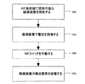
本発明の実施形態による摂取可能なセンサを作動する方法のフローチャートを示す図5を参照する。ブロック500において、摂取可能な撮像装置は、外部源によりRF放射線を照射される。例えば、摂取可能な撮像装置等の装置100は、無線周波数の放射線を生成しているコイル176の近傍にあるいはその中に配置される。幾つかの実施形態では、装置100をコイル176の略内部に挿入することで装置100が強いRF電磁場に挿入される。コイル176は、実質的に強い電磁場を生ずる。幾つかの実施形態では、このような配置は、生体外で、または、装置を摂取する前あるいは装置を生体内領域に挿入する前に行われる。幾つかの実施形態では、無線周波数の放射線は、所定の電力および/または周波数を有する。幾つかの実施形態では、RF放射線の生成部は、数秒間にわたって1.5マイクロWB/m2等、1乃至100マイクロWB/m2の放射線を生成するに好適である。
Reference is made to FIG. 5 showing a flowchart of a method of operating an ingestible sensor according to an embodiment of the present invention. In
ブロック502において、RF放射線からのエネルギーは摂取可能な撮像装置内の構成要素で電圧を誘導する。幾つかの実施形態では、このようなエネルギーは、コンデンサ407と共振状態にあるコイル128等によって集められる。ブロック504において、誘導電圧が十分に高い場合、スイッチが作動されるか切り換えられ、スイッチの位置がオンからオフに、あるいは、オフからオンに切り換えられる。本発明の一実施形態では、装置100を活性化させるか、あるいは、装置100内の構成要素をオンにする信号は、所定のパターンのRFパルス等の所定の信号でもよく、装置100または装置100内の構成要素をオフにする信号は第2の所定のパターンのRFパルス等の別の所定の信号でもよい。一実施例では、装置100またはその構成要素をオフにするに必要なRF信号は、装置100を活性化させるに必要な信号および/または所定の信号と比較してより簡単および/またはより短い信号、例えば、より短い所定のパターンを有するパルスでもよい。他の実施形態では、異なる信号パターンが装置100の動作を制御するために定義されてもよい。
At
ブロック506において、電源126からの電力が装置100の一つ以上の電気的構成要素に供給される。幾つかの実施形態では、スイッチ430が作動されると、一つ以上の構成要素(例えば、送信器127、照明源118、イメージャ116、または、他の構成要素)を含む回路が閉じられる。幾つかの実施形態では、スイッチがオン位置で固定され、且つ、RF放射線が中断された後も電源から装置100の構成要素に電力が供給され続けるよう、スイッチは回路を永久的に閉じてもよい。遠隔制御によりRF放射線を用いて摂取可能な装置を作動する他の方法が実行されてもよい。
At
一つ以上の具体的な実施形態を参照して本発明を説明したが、説明が例示目的であり上述の実施形態に本発明を限定するものとして解釈されてはならない。本願では具体的に説明しないが、本発明の思想および範囲から逸脱することなく様々な変更態様が可能であることが当業者には理解されるであろう。 Although the invention has been described with reference to one or more specific embodiments, the description is for illustrative purposes and should not be construed as limiting the invention to the above-described embodiments. Although not specifically described in the present application, those skilled in the art will appreciate that various modifications can be made without departing from the spirit and scope of the invention.
Claims (25)
イメージャと、
電源と、
動作スイッチとを備え、
前記動作スイッチは、前記撮像装置を摂取する前に無線周波数の放射線によって作動される、装置。 An ingestible imaging device comprising:
With an imager,
Power supply,
An operation switch,
The device wherein the operation switch is activated by radio frequency radiation prior to ingesting the imaging device.
電気的構成要素を更に備え、
前記動作スイッチが作動されると、前記電源から前記電気的構成要素に電力が供給され、
前記電源と前記電気的構成要素が前記装置に設けられる、装置。 The apparatus of claim 1.
Further comprising electrical components;
When the operation switch is activated, power is supplied from the power source to the electrical component;
A device wherein the power source and the electrical components are provided in the device.
コイルを更に備え、
前記コイルが前記無線周波数の放射線を受信する、装置。 The apparatus of claim 1.
A coil,
The apparatus, wherein the coil receives the radio frequency radiation.
コンデンサを更に備え、
前記コイルが前記コンデンサと共振する、装置。 The apparatus according to claim 8.
A capacitor,
An apparatus wherein the coil resonates with the capacitor.
前記摂取可能な撮像装置を外部から印加される無線周波数の放射線で照射することで動作スイッチを作動して、電源から電気的構成要素に電力を供給するステップを備え、
前記電源と前記電気的構成要素が前記装置内に設けられる、方法。 A method of changing the power state of an ingestible imaging device,
Activating the operation switch by irradiating the ingestible imaging device with externally applied radio frequency radiation to provide power from the power source to the electrical components;
The method wherein the power source and the electrical components are provided in the device.
前記装置をコイル内に位置決めするステップを更に備え、
前記コイルが前記無線周波数の放射線を送信する、方法。 The method of claim 13, wherein
Further comprising positioning the device in a coil;
The method wherein the coil transmits the radio frequency radiation.
前記電気的構成要素が送信器であり、
前記送信器が画像データを無線で送信する、方法。 The method of claim 13, wherein
The electrical component is a transmitter;
A method in which the transmitter transmits image data wirelessly.
生体内の画像データを捕捉するステップと、
外部受信器に前記画像データを送信するステップと、を更に備える方法。 The method of claim 13, wherein
Capturing in-vivo image data;
Transmitting the image data to an external receiver.
機械的に固定の動作スイッチと、
前記動作スイッチを作動するに好適な無線周波数の放射線の生成器とを備え、
前記生成器が前記装置の外部にある、システム。 A system for operating an ingestible imaging device, the device comprising:
A mechanically fixed operating switch;
A radio frequency radiation generator suitable for actuating the operation switch;
The system, wherein the generator is external to the device.
前記生成器が一次コイルを備え、
前記一次コイルが前記無線周波数の放射線を送信する、システム。 The system of claim 21, wherein
The generator comprises a primary coil;
The system wherein the primary coil transmits the radio frequency radiation.
前記装置が二次コイルを備え、
前記二次コイルが前記無線周波数の放射線を受信する、システム。 The system of claim 21, wherein
The device comprises a secondary coil;
The system, wherein the secondary coil receives the radio frequency radiation.
前記無線周波数の放射線の生成器が一次コイルを備え、
前記装置が前記一次コイル内に位置決めされる、システム。 The system of claim 21, wherein
The radio frequency radiation generator comprises a primary coil;
A system wherein the device is positioned within the primary coil.
前記生成器が前記装置を作動する第1の信号、および、前記装置を停止する第2の信号を生成する、システム。 The system of claim 21, wherein
A system in which the generator generates a first signal to activate the device and a second signal to deactivate the device.
Applications Claiming Priority (2)
| Application Number | Priority Date | Filing Date | Title |
|---|---|---|---|
| US11/283,867 US20070129602A1 (en) | 2005-11-22 | 2005-11-22 | Device, method and system for activating an in-vivo imaging device |
| PCT/IL2006/001341 WO2007060658A2 (en) | 2005-11-22 | 2006-11-21 | Device, method and system for activating an in-vivo imaging device |
Publications (2)
| Publication Number | Publication Date |
|---|---|
| JP2009516562A true JP2009516562A (en) | 2009-04-23 |
| JP2009516562A5 JP2009516562A5 (en) | 2011-03-10 |
Family
ID=38067627
Family Applications (1)
| Application Number | Title | Priority Date | Filing Date |
|---|---|---|---|
| JP2008541909A Withdrawn JP2009516562A (en) | 2005-11-22 | 2006-11-21 | Apparatus, method and system for operating an in-vivo imaging device |
Country Status (4)
| Country | Link |
|---|---|
| US (1) | US20070129602A1 (en) |
| EP (1) | EP1951100A4 (en) |
| JP (1) | JP2009516562A (en) |
| WO (1) | WO2007060658A2 (en) |
Cited By (4)
| Publication number | Priority date | Publication date | Assignee | Title |
|---|---|---|---|---|
| WO2011074344A1 (en) * | 2009-12-18 | 2011-06-23 | オリンパス株式会社 | Control signal transmitting apparatus |
| JP2011172735A (en) * | 2010-02-24 | 2011-09-08 | Olympus Corp | Biological information acquisition system |
| WO2014125908A1 (en) | 2013-02-14 | 2014-08-21 | オリンパスメディカルシステムズ株式会社 | Activation device |
| JPWO2017154178A1 (en) * | 2016-03-10 | 2019-01-24 | 国立大学法人東北大学 | Wireless communication system, wireless communication method, and wireless device |
Families Citing this family (22)
| Publication number | Priority date | Publication date | Assignee | Title |
|---|---|---|---|---|
| US8882657B2 (en) | 2003-03-07 | 2014-11-11 | Intuitive Surgical Operations, Inc. | Instrument having radio frequency identification systems and methods for use |
| KR20080064155A (en) | 2005-10-14 | 2008-07-08 | 어플라이드 리써치 어쏘시에이츠 뉴질랜드 리미티드 | A method of monitoring a surface feature and apparatus therefor |
| JP2008142410A (en) * | 2006-12-12 | 2008-06-26 | Olympus Corp | Device introduced inside subject |
| ES2303466B1 (en) * | 2007-01-19 | 2009-07-20 | Pedro Guillen Garcia | ARTRO-ENDOSCOPY WITHOUT CABLES. |
| WO2009031640A1 (en) * | 2007-09-07 | 2009-03-12 | Olympus Medical Systems Corp. | In-vivo information acquiring device and power supply control method |
| US20100222670A1 (en) * | 2007-10-04 | 2010-09-02 | Michel Demierre | Device for measuring and method for analysing gastrointestinal motility |
| JP5132335B2 (en) * | 2008-01-29 | 2013-01-30 | 富士フイルム株式会社 | Capsule endoscope and capsule endoscope system |
| US8423122B2 (en) * | 2008-07-10 | 2013-04-16 | Given Imaging Ltd. | Localization of capsule with a synthetic source of quadrupoles and dipoles |
| JP5627067B2 (en) * | 2008-12-01 | 2014-11-19 | オリンパス株式会社 | Living body observation system and driving method of the living body observation system |
| JP5284849B2 (en) * | 2009-03-31 | 2013-09-11 | オリンパス株式会社 | In-vivo observation system |
| US20110077718A1 (en) * | 2009-09-30 | 2011-03-31 | Broadcom Corporation | Electromagnetic power booster for bio-medical units |
| WO2011073987A1 (en) | 2009-12-17 | 2011-06-23 | Given Imaging Ltd. | Device, system and method for activation, calibration and testing of an in-vivo imaging device |
| JP5734614B2 (en) * | 2010-10-08 | 2015-06-17 | オリンパス株式会社 | Biological information acquisition device |
| US9179844B2 (en) | 2011-11-28 | 2015-11-10 | Aranz Healthcare Limited | Handheld skin measuring or monitoring device |
| KR101409844B1 (en) * | 2012-11-26 | 2014-06-19 | 전자부품연구원 | Telemetry apparatus, system, and method for animal experiment |
| EP2938392B1 (en) | 2012-12-31 | 2018-06-27 | Given Imaging Ltd. | Methods and systems for controlling an on/off switch |
| US20140275782A1 (en) * | 2013-03-15 | 2014-09-18 | Check Cap Ltd. | Activation of imaging capsules with alternating current |
| WO2015102745A1 (en) * | 2013-12-31 | 2015-07-09 | Abbott Diabetes Care Inc. | Self-powered analyte sensor and devices using the same |
| CN104068821B (en) * | 2014-06-24 | 2015-12-09 | 深圳市资福技术有限公司 | A kind of human body micro detector and active controller |
| US10013527B2 (en) | 2016-05-02 | 2018-07-03 | Aranz Healthcare Limited | Automatically assessing an anatomical surface feature and securely managing information related to the same |
| US11116407B2 (en) | 2016-11-17 | 2021-09-14 | Aranz Healthcare Limited | Anatomical surface assessment methods, devices and systems |
| WO2018185560A2 (en) | 2017-04-04 | 2018-10-11 | Aranz Healthcare Limited | Anatomical surface assessment methods, devices and systems |
Family Cites Families (52)
| Publication number | Priority date | Publication date | Assignee | Title |
|---|---|---|---|---|
| US3683389A (en) * | 1971-01-20 | 1972-08-08 | Corning Glass Works | Omnidirectional loop antenna array |
| US3971362A (en) * | 1972-10-27 | 1976-07-27 | The United States Of America As Represented By The Administrator Of The National Aeronautics And Space Administration | Miniature ingestible telemeter devices to measure deep-body temperature |
| DE2325193A1 (en) * | 1973-05-18 | 1974-11-28 | Bosch Fernsehanlagen | COLOR TELEVISION CAMERA |
| US4135512A (en) * | 1977-04-15 | 1979-01-23 | Godsey David W | Medication dispensing cup |
| US4172640A (en) * | 1977-12-30 | 1979-10-30 | Polaroid Corporation | Movie camera having supplemental exposure |
| JPS5519124A (en) * | 1978-07-27 | 1980-02-09 | Olympus Optical Co | Camera system for medical treatment |
| US4273431A (en) * | 1979-08-02 | 1981-06-16 | Polaroid Corporation | Adapter for coupling a photographic camera with a viewing device |
| US5993378A (en) * | 1980-10-28 | 1999-11-30 | Lemelson; Jerome H. | Electro-optical instruments and methods for treating disease |
| DE3337455A1 (en) * | 1982-10-15 | 1984-04-19 | Olympus Optical Co., Ltd., Tokio/Tokyo | ENDOSCOPIC PHOTOGRAPHER |
| JPH0664243B2 (en) * | 1986-04-30 | 1994-08-22 | オリンパス光学工業株式会社 | Endoscope |
| US4844076A (en) * | 1988-08-26 | 1989-07-04 | The Johns Hopkins University | Ingestible size continuously transmitting temperature monitoring pill |
| JP3164609B2 (en) * | 1990-10-31 | 2001-05-08 | オリンパス光学工業株式会社 | Endoscope device |
| US5267033A (en) * | 1990-11-28 | 1993-11-30 | Dai Nippon Printing Co., Ltd. | Hollow body inspection system, hollow body inspection apparatus and signal transmission apparatus |
| US5257636A (en) * | 1991-04-02 | 1993-11-02 | Steven J. White | Apparatus for determining position of an endothracheal tube |
| US5279607A (en) * | 1991-05-30 | 1994-01-18 | The State University Of New York | Telemetry capsule and process |
| EP0560470A1 (en) * | 1992-03-07 | 1993-09-15 | Oxley Developments Company Limited | Personnel identification devices |
| US5495114A (en) * | 1992-09-30 | 1996-02-27 | Adair; Edwin L. | Miniaturized electronic imaging chip |
| IL108352A (en) * | 1994-01-17 | 2000-02-29 | Given Imaging Ltd | In vivo video camera system |
| CA2145232A1 (en) * | 1994-03-24 | 1995-09-25 | Arie Avny | Viewing method and apparatus particularly useful for viewing the interior of the large intestine |
| US5583819A (en) * | 1995-01-27 | 1996-12-10 | Single Chip Holdings, Inc. | Apparatus and method of use of radiofrequency identification tags |
| US5886353A (en) * | 1995-04-21 | 1999-03-23 | Thermotrex Corporation | Imaging device |
| US5967979A (en) * | 1995-11-14 | 1999-10-19 | Verg, Inc. | Method and apparatus for photogrammetric assessment of biological tissue |
| US5833603A (en) * | 1996-03-13 | 1998-11-10 | Lipomatrix, Inc. | Implantable biosensing transponder |
| US5909026A (en) * | 1996-11-12 | 1999-06-01 | California Institute Of Technology | Integrated sensor with frame memory and programmable resolution for light adaptive imaging |
| US6117529A (en) * | 1996-12-18 | 2000-09-12 | Gunther Leising | Organic electroluminescence devices and displays |
| US6393431B1 (en) * | 1997-04-04 | 2002-05-21 | Welch Allyn, Inc. | Compact imaging instrument system |
| US6106457A (en) * | 1997-04-04 | 2000-08-22 | Welch Allyn, Inc. | Compact imaging instrument system |
| US5929901A (en) * | 1997-10-06 | 1999-07-27 | Adair; Edwin L. | Reduced area imaging devices incorporated within surgical instruments |
| US6043839A (en) * | 1997-10-06 | 2000-03-28 | Adair; Edwin L. | Reduced area imaging devices |
| US5986693A (en) * | 1997-10-06 | 1999-11-16 | Adair; Edwin L. | Reduced area imaging devices incorporated within surgical instruments |
| US6240312B1 (en) * | 1997-10-23 | 2001-05-29 | Robert R. Alfano | Remote-controllable, micro-scale device for use in in vivo medical diagnosis and/or treatment |
| IL122602A0 (en) * | 1997-12-15 | 1998-08-16 | Tally Eitan Zeev Pearl And Co | Energy management of a video capsule |
| US6594036B1 (en) * | 1998-05-28 | 2003-07-15 | Sandisk Corporation | Analog/multi-level memory for digital imaging |
| US6072383A (en) * | 1998-11-04 | 2000-06-06 | Checkpoint Systems, Inc. | RFID tag having parallel resonant circuit for magnetically decoupling tag from its environment |
| US8636648B2 (en) * | 1999-03-01 | 2014-01-28 | West View Research, Llc | Endoscopic smart probe |
| IL177381A0 (en) * | 2000-03-08 | 2006-12-10 | Given Imaging Ltd | A device for in vivo imaging |
| WO2002054932A2 (en) * | 2001-01-16 | 2002-07-18 | Given Imaging Ltd. | System and method for wide field imaging of body lumens |
| AU2002307759A1 (en) * | 2001-04-04 | 2002-10-21 | Given Imaging Ltd. | Induction powered in vivo imaging device |
| US6934573B1 (en) * | 2001-07-23 | 2005-08-23 | Given Imaging Ltd. | System and method for changing transmission from an in vivo sensing device |
| IL151049A0 (en) * | 2001-08-02 | 2003-04-10 | Given Imaging Ltd | In vivo imaging methods and devices |
| ATE532453T1 (en) * | 2001-09-24 | 2011-11-15 | Given Imaging Ltd | SYSTEM FOR CONTROL OF A DEVICE IN VIVO |
| US20050058701A1 (en) * | 2003-01-29 | 2005-03-17 | Yossi Gross | Active drug delivery in the gastrointestinal tract |
| JP4231707B2 (en) * | 2003-02-25 | 2009-03-04 | オリンパス株式会社 | Capsule medical device |
| DE10318205A1 (en) * | 2003-04-22 | 2004-11-25 | Siemens Ag | Computer supported 3-D imaging for capsule endoscope takes sequence of single images and processes them using overlapping pattern recognition algorithm to display surroundings |
| WO2004112592A1 (en) * | 2003-06-24 | 2004-12-29 | Olympus Corporation | Capsule type medical device communication system, capsule type medical device, and biological information reception device |
| JP4590171B2 (en) * | 2003-08-29 | 2010-12-01 | オリンパス株式会社 | Capsule type medical device and medical device equipped with the capsule type medical device |
| JP4139296B2 (en) * | 2003-09-10 | 2008-08-27 | オリンパス株式会社 | Intra-subject introduction apparatus and intra-subject introduction system |
| JP4153852B2 (en) * | 2003-09-18 | 2008-09-24 | オリンパス株式会社 | Energy supply coil and wireless in-vivo information acquisition system using the same |
| US20050124875A1 (en) * | 2003-10-01 | 2005-06-09 | Olympus Corporation | Vivo observation device |
| JP4054319B2 (en) * | 2004-03-29 | 2008-02-27 | オリンパス株式会社 | Power supply |
| JP4009617B2 (en) * | 2004-05-26 | 2007-11-21 | オリンパス株式会社 | Position relation detection apparatus and position relation detection system |
| US8257248B2 (en) * | 2005-03-09 | 2012-09-04 | Olympus Corporation | Body-insertable apparatus and body-insertable apparatus system |
-
2005
- 2005-11-22 US US11/283,867 patent/US20070129602A1/en not_active Abandoned
-
2006
- 2006-11-21 JP JP2008541909A patent/JP2009516562A/en not_active Withdrawn
- 2006-11-21 WO PCT/IL2006/001341 patent/WO2007060658A2/en active Application Filing
- 2006-11-21 EP EP06809890A patent/EP1951100A4/en not_active Withdrawn
Cited By (5)
| Publication number | Priority date | Publication date | Assignee | Title |
|---|---|---|---|---|
| WO2011074344A1 (en) * | 2009-12-18 | 2011-06-23 | オリンパス株式会社 | Control signal transmitting apparatus |
| JP2011125534A (en) * | 2009-12-18 | 2011-06-30 | Olympus Corp | Transmitter for activation control signal |
| JP2011172735A (en) * | 2010-02-24 | 2011-09-08 | Olympus Corp | Biological information acquisition system |
| WO2014125908A1 (en) | 2013-02-14 | 2014-08-21 | オリンパスメディカルシステムズ株式会社 | Activation device |
| JPWO2017154178A1 (en) * | 2016-03-10 | 2019-01-24 | 国立大学法人東北大学 | Wireless communication system, wireless communication method, and wireless device |
Also Published As
| Publication number | Publication date |
|---|---|
| WO2007060658A3 (en) | 2009-04-09 |
| EP1951100A4 (en) | 2009-12-30 |
| EP1951100A2 (en) | 2008-08-06 |
| WO2007060658A2 (en) | 2007-05-31 |
| US20070129602A1 (en) | 2007-06-07 |
Similar Documents
| Publication | Publication Date | Title |
|---|---|---|
| JP2009516562A (en) | Apparatus, method and system for operating an in-vivo imaging device | |
| CN100475121C (en) | Radio-type in-subject information acquisition system and device for introduction into subject | |
| JP5188880B2 (en) | Capsule type medical device and method for charging capsule type medical device | |
| EP1665976A1 (en) | In-subject introducing device and wireless in-subject information capturing system | |
| EP1875852B1 (en) | In-vivo information acquiring apparatus | |
| US7837617B2 (en) | Intrabody introduced device | |
| JP5337013B2 (en) | Start control signal transmitter | |
| JP2004261240A (en) | Capsule type medical instrument | |
| JP2005073934A (en) | Medical device | |
| JP4959965B2 (en) | Body cavity introduction device placement system | |
| JP2010240252A (en) | In-vivo observation system and drive method therefor | |
| JP2010110533A (en) | Wireless electric supply system | |
| JP5628602B2 (en) | In-vivo information acquisition device | |
| JP2005237460A (en) | Wireless information acquisition apparatus in body of subject and wireless information acquisition method in body of subject | |
| JP2011130840A (en) | Biodata acquiring system | |
| JP4848851B2 (en) | Biopsy system | |
| JP2010240144A (en) | Body inside monitoring system | |
| JP4383134B2 (en) | Wireless in-vivo information acquisition device | |
| JP4335086B2 (en) | Intra-subject introduction device | |
| JP2005103147A (en) | Radio type intra-examinee-body information acquisition device and radio type intra-examinee-body information acquisition system | |
| JP2005080842A (en) | Internal guide device for specimen and wireless type internal information acquisition system for specimen | |
| US8663094B2 (en) | In-vivo information acquiring system | |
| JP2011125441A (en) | Housing container containing living body information acquiring apparatus | |
| JP4590175B2 (en) | Wireless in-vivo information acquisition system | |
| US20190110660A1 (en) | Implantable communication system starter system and methods |
Legal Events
| Date | Code | Title | Description |
|---|---|---|---|
| A621 | Written request for application examination |
Free format text: JAPANESE INTERMEDIATE CODE: A621 Effective date: 20091120 |
|
| A521 | Written amendment |
Free format text: JAPANESE INTERMEDIATE CODE: A523 Effective date: 20101122 |
|
| A521 | Written amendment |
Free format text: JAPANESE INTERMEDIATE CODE: A523 Effective date: 20110124 |
|
| A761 | Written withdrawal of application |
Free format text: JAPANESE INTERMEDIATE CODE: A761 Effective date: 20110627 |