JP2009515250A - Near field communication host controller interface - Google Patents
Near field communication host controller interface Download PDFInfo
- Publication number
- JP2009515250A JP2009515250A JP2008538828A JP2008538828A JP2009515250A JP 2009515250 A JP2009515250 A JP 2009515250A JP 2008538828 A JP2008538828 A JP 2008538828A JP 2008538828 A JP2008538828 A JP 2008538828A JP 2009515250 A JP2009515250 A JP 2009515250A
- Authority
- JP
- Japan
- Prior art keywords
- command
- message
- data
- response
- host
- Prior art date
- Legal status (The legal status is an assumption and is not a legal conclusion. Google has not performed a legal analysis and makes no representation as to the accuracy of the status listed.)
- Pending
Links
- 230000006854 communication Effects 0.000 title claims abstract description 38
- 238000004891 communication Methods 0.000 title claims abstract description 38
- 230000004044 response Effects 0.000 claims abstract description 118
- 238000000034 method Methods 0.000 claims abstract description 65
- 230000008569 process Effects 0.000 claims description 29
- 230000005540 biological transmission Effects 0.000 claims description 15
- 238000001514 detection method Methods 0.000 claims description 6
- 238000011010 flushing procedure Methods 0.000 claims description 2
- 230000007704 transition Effects 0.000 claims 1
- 238000010586 diagram Methods 0.000 description 52
- 230000006870 function Effects 0.000 description 6
- 101000703343 Escherichia coli (strain K12) Putative peptide chain release factor homolog Proteins 0.000 description 1
- 230000007175 bidirectional communication Effects 0.000 description 1
- 238000013461 design Methods 0.000 description 1
- 238000011161 development Methods 0.000 description 1
- 238000009434 installation Methods 0.000 description 1
- 238000004519 manufacturing process Methods 0.000 description 1
- 238000012986 modification Methods 0.000 description 1
- 230000004048 modification Effects 0.000 description 1
- 238000012545 processing Methods 0.000 description 1
Images


Classifications
-
- G—PHYSICS
- G06—COMPUTING; CALCULATING OR COUNTING
- G06F—ELECTRIC DIGITAL DATA PROCESSING
- G06F9/00—Arrangements for program control, e.g. control units
- G06F9/06—Arrangements for program control, e.g. control units using stored programs, i.e. using an internal store of processing equipment to receive or retain programs
- G06F9/46—Multiprogramming arrangements
- G06F9/54—Interprogram communication
-
- H—ELECTRICITY
- H04—ELECTRIC COMMUNICATION TECHNIQUE
- H04L—TRANSMISSION OF DIGITAL INFORMATION, e.g. TELEGRAPHIC COMMUNICATION
- H04L69/00—Network arrangements, protocols or services independent of the application payload and not provided for in the other groups of this subclass
- H04L69/30—Definitions, standards or architectural aspects of layered protocol stacks
- H04L69/32—Architecture of open systems interconnection [OSI] 7-layer type protocol stacks, e.g. the interfaces between the data link level and the physical level
-
- G—PHYSICS
- G06—COMPUTING; CALCULATING OR COUNTING
- G06F—ELECTRIC DIGITAL DATA PROCESSING
- G06F15/00—Digital computers in general; Data processing equipment in general
- G06F15/16—Combinations of two or more digital computers each having at least an arithmetic unit, a program unit and a register, e.g. for a simultaneous processing of several programs
-
- H—ELECTRICITY
- H04—ELECTRIC COMMUNICATION TECHNIQUE
- H04W—WIRELESS COMMUNICATION NETWORKS
- H04W4/00—Services specially adapted for wireless communication networks; Facilities therefor
- H04W4/80—Services using short range communication, e.g. near-field communication [NFC], radio-frequency identification [RFID] or low energy communication
-
- H—ELECTRICITY
- H04—ELECTRIC COMMUNICATION TECHNIQUE
- H04L—TRANSMISSION OF DIGITAL INFORMATION, e.g. TELEGRAPHIC COMMUNICATION
- H04L69/00—Network arrangements, protocols or services independent of the application payload and not provided for in the other groups of this subclass
- H04L69/12—Protocol engines
-
- H—ELECTRICITY
- H04—ELECTRIC COMMUNICATION TECHNIQUE
- H04L—TRANSMISSION OF DIGITAL INFORMATION, e.g. TELEGRAPHIC COMMUNICATION
- H04L69/00—Network arrangements, protocols or services independent of the application payload and not provided for in the other groups of this subclass
- H04L69/30—Definitions, standards or architectural aspects of layered protocol stacks
- H04L69/32—Architecture of open systems interconnection [OSI] 7-layer type protocol stacks, e.g. the interfaces between the data link level and the physical level
- H04L69/322—Intralayer communication protocols among peer entities or protocol data unit [PDU] definitions
- H04L69/324—Intralayer communication protocols among peer entities or protocol data unit [PDU] definitions in the data link layer [OSI layer 2], e.g. HDLC
Abstract
本発明は、NFCH(Near Field Communication Host)とNFCデバイスとの間の通信インターフェイス、およびNFC HCI(Near Field Communication Host Controller Interface)の制御方法を提供する。この方法においてコマンドメッセージは、ホストからデバイスへと伝送される。コマンドメッセージは、記録データ、デバイスの読取りデータ、デバイスに対する既定データの伝送要求およびデバイス設定の一つを含む。関連するコマンドの実行結果を通知する応答メッセージは、コマンドメッセージに応答してデバイスからホストへ伝送される。このあと、イベントメッセージは、必要に応じてデバイスからホストへ伝送される。The present invention provides a communication interface between an NFCH (Near Field Communication Host) and an NFC device, and an NFC HCI (Near Field Communication Host Controller Interface) control method. In this method, command messages are transmitted from the host to the device. The command message includes one of recording data, device read data, a request for transmitting predetermined data to the device, and device settings. A response message notifying the execution result of the related command is transmitted from the device to the host in response to the command message. Thereafter, the event message is transmitted from the device to the host as necessary.
Description
本発明は、近距離通信(NFC)ホストとNFCデバイスとの間の通信インターフェイスに関する。 The present invention relates to a communication interface between a near field communication (NFC) host and an NFC device.
NFCホストとNFCデバイスまたはNFCチップセットとの間の通信インターフェイスに関して、汎用性と互換性が必要とされている。携帯電話機のMSMチップや可搬型機器のマイクロコントローラユニット(MCU)のようなホストとホストに接続されたデバイスまたはチップセットとの間のインターフェイスは、大きな重要性をもって取扱われるべきである。 There is a need for versatility and compatibility with respect to communication interfaces between NFC hosts and NFC devices or NFC chipsets. The interface between a host and a device or chipset connected to the host, such as a mobile phone MSM chip or a portable device microcontroller unit (MCU), should be handled with great importance.
図1は、様々なNFCホスト(NFCH)と様々なNFCデバイスまたはNFCチップセット(NFCC)との間のインターフェイスを図示する。NFCH A 110とNFCC A 210との間のインターフェイスは、シリアルバスを介してNFCC A 210と接続されるドライバA 113のために適切に実現された関連するドライバインターフェイス112に基づいて上位階層111に接続される。他のNFCH B 120と他のNFCC B 220との間のインターフェイスは、シリアルバスを介してNFCC B 220と接続されるドライバB 123のために適切に実現された関連するドライバインターフェイス122に基づいて上位階層121に接続される。別のNFCH C 130と別のNFCC 230との間のインターフェイスは、シリアルバスを介してNFCC C 230と接続されるドライバC 133のために適切に実現された関連するドライバインターフェイス132に基づいて上位階層131に接続される。
FIG. 1 illustrates an interface between various NFC hosts (NFCH) and various NFC devices or NFC chipsets (NFCC). The interface between NFCH A 110 and NFCC A 210 is connected to the
図1を参照すると、既定のホストのために、既定のホストと接続されるデバイスまたはチップセットは、デバイスまたはチップセットのために適切に実現されたドライバを用いて関連するドライバインターフェイスを確立する。従って、ホストとチップセットまたはデバイスとの間のインターフェイスは、互いに異なるため相互互換性または汎用性を保証しない。 Referring to FIG. 1, for a given host, a device or chipset connected to the given host establishes an associated driver interface with a driver appropriately implemented for the device or chipset. Therefore, since the interface between the host and the chipset or device is different from each other, mutual compatibility or versatility is not guaranteed.
図2は、ホストとチップセットまたはデバイスとの間のインターフェイスにおいて、相互互換性または汎用性が保証されない場合に発生し得る欠点を図示する。NFCC 210のために適切なインターフェイスが既定のNFCH 100に関連して確立される場合、他のNFCC 220および230は、異なるドライバ123および133に基づくのでホスト100と接続出来ない。
FIG. 2 illustrates the disadvantages that can occur when interoperability or versatility is not guaranteed at the interface between the host and the chipset or device. If an appropriate interface for NFCC 210 is established in connection with the
ホストとホストに接続されるデバイスまたはチップセットとの間のインターフェイスが各ホスト、各デバイス、または各チップセットにおいて異なる場合、相互互換性または汎用性は保証されない。 If the interface between the host and the device or chipset connected to the host is different in each host, each device, or each chipset, mutual compatibility or versatility is not guaranteed.
上述のように、図2を参照すると、異なるインターフェイスを必要とする異なるデバイス間の制御インターフェイスは、各ホストおよび各デバイスのために適切な新しいドライバおよび新しいドライバインターフェイスの設計と開発を要求し、ホストにおけるだけでなくデバイスまたはチップセットにおけるデバイス中に、ドライバとドライバインターフェイスの搭載を要求する。 As described above, referring to FIG. 2, the control interface between different devices that require different interfaces requires the design and development of new drivers and new driver interfaces appropriate for each host and each device, Requires the installation of drivers and driver interfaces not only in devices but also in devices in devices or chipsets.
本発明の目的は、ホストとホストに接続されるデバイスまたはチップセットとの間のインターフェイスを定義することであり、定義されたインターフェイスに適合することによって、異なるデバイス間のホストコントローラインターフェイスに対する汎用性および互換性を保証することである。 An object of the present invention is to define an interface between a host and a device or chipset connected to the host, and by adapting to the defined interface, the versatility to the host controller interface between different devices and It is to ensure compatibility.
本発明の別の目的は、NFCHとNFCデバイスまたはNFCチップセットとの間でデータを伝送するためのデータフォーマットおよびデータフォーマットのプロセスを定義することと、定義されたフォーマットおよびそのプロセスに適合することによってデバイス間のインターフェイスを提供することと、これにより異なるデバイス間のホストコントローラインターフェイスに対する汎用性および互換性を保証することである。 Another object of the present invention is to define a data format and data format process for transmitting data between NFCH and NFC device or NFC chipset, and to conform to the defined format and process To provide an interface between devices, thereby ensuring versatility and compatibility for host controller interfaces between different devices.
これらの利点および他の利点を達成するために、また、本発明の目的に従って、具体的に示し広く記述したように、ホストとホストに接続されるデバイスとの間の通信インターフェイスにおけるホストとデバイスとの間の通信方法が提供される。その通信方法は、ホストからデバイスへコマンドメッセージを伝送することと、コマンドメッセージに応答してデバイスからホストへ応答メッセージを伝送することと、ホストとデバイスとの間でデータを伝送することと、そして必要な場合、デバイスからホストへイベントメッセージを伝送することとを含む。 To achieve these and other advantages, and in accordance with the purposes of the present invention, as specifically shown and broadly described, the host and device in the communication interface between the host and the device connected to the host A communication method is provided. The communication method includes transmitting a command message from the host to the device, transmitting a response message from the device to the host in response to the command message, transmitting data between the host and the device, and Transmitting event messages from the device to the host if necessary.
本発明の別の局面によれば、ホストとホストに接続されるデバイスとの間の通信インターフェイスにおけるホストとデバイスとの間の通信方法が提供される。その通信方法は、ホストからデバイスへコマンドメッセージ(コマンドメッセージは、メッセージの種類を表現するデータと、メッセージの内容を表現するデータと、追加のデータとを含む)を伝送することと、デバイスからイベントメッセージを伝送するか、または応答メッセージ(応答メッセージは、メッセージの種類を表現するデータと、メッセージの内容を表現するデータと、追加のデータとを含む)を伝送することと、そして必要な場合、コマンドメッセージまたは応答メッセージに応答して、データおよびそのデータを含むメッセージを表現する情報をホストとデバイスとの間で伝送することとを含む。 According to another aspect of the present invention, a communication method between a host and a device in a communication interface between the host and a device connected to the host is provided. The communication method includes transmitting a command message from the host to the device (the command message includes data representing the type of message, data representing the content of the message, and additional data), and an event from the device. Transmitting a message or transmitting a response message (which includes data representing the type of message, data representing the content of the message, and additional data), and if necessary, In response to a command message or a response message, transmitting data and information representing a message including the data between the host and the device.
さらに本発明の別の局面によれば、ホストとホストに接続されるデバイスとの間の通信インターフェイスにおける近距離通信ホストと近距離通信デバイスとの間の通信方法が提供される。その通信方法は、ホストからデバイスへコマンドメッセージ(コマンドメッセージは、記録データ、デバイスの読取りデータ、デバイスに対する既定データの伝送要求およびデバイス設定の一つを含む)を伝送することと、コマンドメッセージに応答して、関連したコマンドの実行結果を通知する応答メッセージをデバイスからホストへ伝送することと、そして必要な場合、デバイスからホストへイベントメッセージを伝送することとを含む。 According to still another aspect of the present invention, a communication method between a short-range communication host and a short-range communication device in a communication interface between the host and a device connected to the host is provided. The communication method transmits a command message from the host to the device (the command message includes one of recording data, read data of the device, a request for transmitting predetermined data to the device, and device settings), and responds to the command message. Then, a response message notifying the execution result of the related command is transmitted from the device to the host, and if necessary, an event message is transmitted from the device to the host.
本発明によれば、ホストMCUとNFCデバイスまたはチップセットとの間の通信における汎用性および互換性は保証される。 According to the present invention, versatility and compatibility in communication between the host MCU and the NFC device or chipset is guaranteed.
本発明によれば、NFCホストとNFCデバイスまたはチップセットとの間の通信におけるコマンドメッセージ、応答メッセージ、データメッセージ、およびイベントメッセージに関するインターフェイスの汎用性および互換性は保証される。 According to the present invention, the versatility and compatibility of interfaces for command messages, response messages, data messages, and event messages in communication between an NFC host and an NFC device or chipset is guaranteed.
本発明によれば、NFCデバイスまたはNFCチップセットは、NFCHの局面におけるデバイスドライバ、ミドルウェア、またはアプリケーションを改変すること無く用いられ得る。また、本発明によれば、NFCデバイスまたはNFCチップセットの局面において各ホストのための適切なドライバが実現されなくとも、ホストとNFCデバイスまたはNFCチップセットとの間のインターフェイスにおける汎用性および互換性は達成され得る。 According to the present invention, an NFC device or NFC chipset can be used without modifying device drivers, middleware, or applications in the NFCH aspect. Also, according to the present invention, versatility and compatibility in the interface between the host and the NFC device or NFC chipset even if an appropriate driver for each host is not realized in the NFC device or NFC chipset aspect. Can be achieved.
(本発明を実行するための最良のモード)
図3は、本発明によるホストコントローラインターフェイス(HCI)の概念を説明する図面である。NFCHとNFCチップセットまたはNFCデバイスは、本発明によるフォーマットとプロセスに従っている。本発明によると、任意のNFCH100は、種々のドライバに対応するインターフェイス112、122、132に関する共通インターフェイスドライバ120を有しており、任意のNFCチップセット(以下、NFCデバイスは含まれる)200は、HCIを含む共通デバイスドライバ130に、通信ライン(例えば、一実施形態としてシリアルバス)を介して接続される。また、共通デバイスドライバ用の拡張インターフェイス125は、拡張性を与えるために提供される。従って、ベンダーによって自由に定義可能であり、かつ使用可能であるドライバ領域135が、さらに提供される。
(Best mode for carrying out the present invention)
FIG. 3 is a diagram for explaining the concept of the host controller interface (HCI) according to the present invention. The NFCH and NFC chipset or NFC device follow the format and process according to the present invention. According to the present invention, any NFCH 100 has a
図3を参照すると、デバイスをNFCHとNFCチップセットとの間のインターフェイスに関連して決定されるフォーマットとプロセスに従わせることによって、異なるデバイス間のデータ伝送を含む一連の制御動作における相互互換性と汎用性は保証できる。 Referring to FIG. 3, interoperability in a series of control operations including data transmission between different devices by allowing the device to follow the format and process determined in relation to the interface between the NFCH and the NFC chipset. And versatility can be guaranteed.
図4は、本発明によるホストコントローラインターフェイスを適用した場合の利点を説明する図面である。携帯電話機やデジタルテレビ受像器のようなホストが、本発明のNFC HCIに従う場合、ホストは、どのようなNFCチップセット(NFC IC)に関するデバイスドライバまたはミドルウェア(MW)無しで保証された互換性と汎用性をもって自由に使うことが出来る。また、NFC ICがNFC HCIに従う場合、NFC ICは、どのようなNFCホストに関するホストドライバに関連する困難性無しで保証された互換性と汎用性をもって自由に使うことが出来る。 FIG. 4 is a diagram for explaining advantages when the host controller interface according to the present invention is applied. If a host, such as a mobile phone or digital television receiver, complies with the NFC HCI of the present invention, the host is guaranteed compatible with no device driver or middleware (MW) for any NFC chipset (NFC IC). It can be used freely with versatility. Also, if the NFC IC conforms to NFC HCI, the NFC IC can be freely used with guaranteed compatibility and versatility without the difficulties associated with host drivers for any NFC host.
図5は、本発明の一実施形態によるNFCHおよびNFCデバイスの例示的な構造を示す図である。図5は、ホスト500、NFCデバイス600およびセキュアエレメント700の内部構造を図示している。ホスト(すなわちNFCH)500は、デバイス発見とモード切換えスタックの上位に位置する、論理リンク制御プロトコル(LLCP)、リーダ/ライタ、NFCデータ交換フォーマット(NDEF)、カードエミュレーションモジュール(例えば、NFCIP−1、ISO 14443B)およびレコード型定義(RTD)を含んでいる。また、ホスト500は、それぞれのセキュアエレメント入力/出力(I/O)部(例えば、セキュアエレメントI/Oファームウェア(F/W)とセキュアエレメントI/Oハードウェア(H/W))、シリアル入力/出力(I/O)部(例えば、シリアルI/Oファームウェア(F/W)およびシリアルI/Oハードウェア(H/W))をさらに含んでいる。そして、ホスト500は、NFC HCIに基づいて、NFCデバイス600とセキュアエレメント700とに接続されている。
FIG. 5 is a diagram illustrating an exemplary structure of an NFCH and NFC device according to an embodiment of the present invention. FIG. 5 illustrates the internal structure of the
NFCデバイス600は、NFC HCIに基づいて、ホスト500とセキュアエレメント700とに接続され、さらに、シリアルI/O部(例えば、シリアルI/O F/WとSE I/O F/WおよびH/W)に基づいて、ホスト500とセキュアエレメント700とに接続される。また、NFCデバイス600は、デバイス発見とモード切換えスタック、カードエミュレーションモジュールおよびNFC RF H/Wを含んでいる。
The NFC device 600 is connected to the
セキュアエレメント700は、カードアプリケーション、NFC HCI、セキュアエレメントI/O部(例えば、セキュアエレメントI/O F/WおよびH/W)を含み、ホスト500とNFCデバイス600とに接続されている。
The
ここで、シリアルI/O F/Wは、汎用非同期受信器送信器(UART)または汎用シリアルバス(USB)のようなシリアルポートを制御する。図5は、HCIパス、物理的なシリアルI/Oパス、セキュアエレメントのための物理的なパスを、破線と実線で図示している。 Here, the serial I / O F / W controls a serial port such as a universal asynchronous receiver transmitter (UART) or a universal serial bus (USB). FIG. 5 illustrates the HCI path, the physical serial I / O path, and the physical path for the secure element with a broken line and a solid line.
図5に図示したホスト−デバイス−セキュアエレメントの構造は、単なる一例であり、本発明のNFCシステムは、ここに図示された実施形態に限定されるものではない。上記のホスト、デバイスおよびカードベースセキュアシステムのそれぞれの内部構造、物理的構造および、搭載されたモジュールを含む通信方法は、さらに自由に設計と改変が出来て、当業者によって容易に実現可能である。 The structure of the host-device-secure element shown in FIG. 5 is merely an example, and the NFC system of the present invention is not limited to the embodiment shown here. The communication method including the internal structure, physical structure, and mounted module of each of the above host, device, and card-based secure system can be further freely designed and modified, and can be easily realized by those skilled in the art. .
図6は、本発明の一実施形態によるリーダ/ライタモードのインターフェイス制御プロセスの一例を示す図である。図6は、プロセス、すなわちホストAとNFCデバイスとの間で実行出来るホストコントローラインターフェイス(HCI)を示す。ホストは、デバイス走査プロセスをデバイス上で実行する(S110)。それに応じて、デバイス発見、単一デバイス検知が実行される。その結果、カード検知応答(Card_Detected)がホストに伝達される(S120)。ホストは、カード検知に応答してカード読取りプロセス(Read_Card)を実行する(S130)。この時点で、データ交換プロトコルが適用出来る。データは、NFCデバイスからNFCHに受信される(Data_Received)(S140)。データ受信が完了すると、ホストは、カード選択解除プロセス(Deselect_Card)を実行する(S150)。カード選択解除プロセスが完了すると、NFCデバイスは、関連した応答(Deselect_Card)をNFCホスト上で実行する(S160)。 FIG. 6 is a diagram illustrating an example of an interface control process in the reader / writer mode according to an embodiment of the present invention. FIG. 6 shows a host controller interface (HCI) that can be executed between processes, ie, host A and the NFC device. The host executes a device scanning process on the device (S110). Accordingly, device discovery and single device detection are performed. As a result, a card detection response (Card_Detected) is transmitted to the host (S120). In response to the card detection, the host executes a card reading process (Read_Card) (S130). At this point, a data exchange protocol can be applied. Data is received on the NFCH from the NFC device (Data_Received) (S140). When the data reception is completed, the host executes a card selection release process (Select_Card) (S150). When the card deselection process is completed, the NFC device executes an associated response (Select_Card) on the NFC host (S160).
図6を参照すると、本発明によるHCIにおいてコマンドと応答とは、一対で動作する。詳細は後述する。 Referring to FIG. 6, a command and a response operate in a pair in the HCI according to the present invention. Details will be described later.
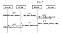
図7は、本発明の一実施形態によるピアモードにおけるインターフェイス制御プロセスの一例を示す図である。すなわち、NFC HCIがピアツーピア通信においてどのように動作するかを図7は示している。ホストAとホストBとは、それぞれNFC AとNFC Bとに基づき相互に通信する。ホストAは、NFC AとNFC Bとに基づきホストBのセッションオープン(LLC_Open_Session)プロセスを実行する(S210−S230)。ホストBは、NFC BとNFC Aとに基づきホストAに対して、セッションオープン肯定応答(LLC_Open_Session_Ack)プロセスを実行する。すなわち、ピアツーピア通信は、本発明のNFC HCIに従うことによって保証される、互換性と汎用性をもって自由に実行出来る。 FIG. 7 is a diagram illustrating an example of an interface control process in peer mode according to an embodiment of the present invention. That is, FIG. 7 shows how NFC HCI operates in peer-to-peer communication. Host A and host B communicate with each other based on NFC A and NFC B, respectively. The host A executes a session open (LLC_Open_Session) process of the host B based on NFC A and NFC B (S210-S230). Host B executes a session open acknowledgment (LLC_Open_Session_Ack) process for host A based on NFC B and NFC A. That is, peer-to-peer communication can be freely performed with compatibility and versatility that is guaranteed by following the NFC HCI of the present invention.
図8は、本発明の一実施形態によるデータを伝送するための例示的な方法を示す図である。ここで、データを伝送する際のオーバーフローを防止することによって、データ損失無くデータを伝送するための方法を図示している。すなわち、データ送信側は、デバイスバッファのサイズを考慮して、データ分割を行い、分割されたデータおよび関連データを受信側に送信する。データ受信側は、分割されたデータを再構築するために、分割されて送信されたデータを受信する。その結果、原データは損失無く受信することが出来る。分割されたデータを送信する場合の関連データの一例は、データサイズに関連したデータを含んでいる。受信側のデバイスのバッファサイズに関連したデータは、送信動作中に取得される。それから、データは、取得されたバッファサイズに関連したデータを用いて送信される。 FIG. 8 is a diagram illustrating an exemplary method for transmitting data according to an embodiment of the present invention. Here, a method for transmitting data without data loss by preventing overflow during data transmission is shown. That is, the data transmission side performs data division in consideration of the size of the device buffer, and transmits the divided data and related data to the reception side. The data receiving side receives the divided and transmitted data in order to reconstruct the divided data. As a result, the original data can be received without loss. An example of related data when transmitting divided data includes data related to the data size. Data related to the buffer size of the receiving device is obtained during the transmission operation. The data is then transmitted using the data associated with the obtained buffer size.
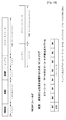
図9は、本発明の一実施形態によるNFCHとNFCデバイスとの間のインターフェイス制御プロセスの一例を示す図である。すなわち、図9は、デバイスのバッファサイズを考慮してデータを分割し、分割されたデータを送信することにより、データ損失を防止する一連のプロセスを示す。 FIG. 9 is a diagram illustrating an example of an interface control process between an NFCH and an NFC device according to an embodiment of the present invention. That is, FIG. 9 shows a series of processes for preventing data loss by dividing the data in consideration of the buffer size of the device and transmitting the divided data.
デバイスのバッファサイズを要求するコマンド(HCI_GET_BUFFER_SIZEコマンドメッセージ)は、NFCHからHFCデバイスへ伝達される(S310)。 A command (HCI_GET_BUFFER_SIZE command message) requesting the buffer size of the device is transmitted from the NFCH to the HFC device (S310).
NFCデバイスは、mバイトによって表現されるバッファのサイズデータ(HCI_GET_BUFFER_SIZE応答メッセージ)を、デバイスのバッファサイズ要求コマンドに応答してNFCHに伝送する(S320)。NFCHは、最初のデータ(それは、デバイスのバッファサイズのデータに基づくバッファサイズ(mバイト)を考慮して、送信すべきデータのサイズを分割することによって得られた最初のデータである)を送信する(コマンドプロトコルメッセージ)(S330)。NFCデバイスは、データが完全に受信出来た応答(HCI_SIZE_COMPLETE_DATAイベント)を送信する(S340)。この応答は、mバイトを返すことにより実行出来る。次の動作、S350、S360およびS370は、同様なやり方で残りのデータを送信および応答を受信するプロセスを記述する。NFCHからNFCデバイスへ送信される全てのデータの送信がこの様な方法で完了した場合、NFCデバイスは、NFCHへのデータ伝送が完了済みであることを通知するメッセージを送信し、その後、プロセスを終了する(応答プロトコルメッセージ)。この応答は、必要なパラメータを返すことにより実行出来る。 The NFC device transmits buffer size data expressed by m bytes (HCI_GET_BUFFER_SIZE response message) to the NFCH in response to the device buffer size request command (S320). The NFCH transmits the first data (which is the first data obtained by dividing the size of the data to be transmitted taking into account the buffer size (mbytes) based on the device buffer size data) (Command protocol message) (S330). The NFC device transmits a response (HCI_SIZE_COMPLETE_DATA event) that data has been completely received (S340). This response can be executed by returning m bytes. The next operation, S350, S360 and S370, describes the process of sending the remaining data and receiving the response in a similar manner. If the transmission of all data sent from the NFCH to the NFC device is completed in this way, the NFC device sends a message notifying that the data transmission to the NFCH has been completed, and then processes the process. End (response protocol message). This response can be executed by returning the necessary parameters.
図10は、本発明の一実施形態によるNFCHとNFCチップセット(または、NFCデバイス)との間のインターフェイスの例示的な構造を示す図である。通信は、コマンド30、応答40、およびイベント50に基づいて、NFCH10とNFCデバイス20との間で実行される。コマンド30は、NFCH10からNFCデバイス20に伝達される。応答40は、NFCデバイス20からNFCH10に伝達される。イベント50は、NFCデバイス20からNFCH10に伝達され、そしてコマンドおよび応答に関して独立である。コマンド30と応答40は、一対で動作する。イベントプロセスは、非同期のメッセージングを通じて実行される。
FIG. 10 is a diagram illustrating an exemplary structure of an interface between an NFCH and an NFC chipset (or NFC device) according to an embodiment of the present invention. Communication is performed between the
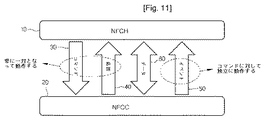
図11は、本発明の一実施形態によるNFCHとNFCチップセット(または、NFCデバイス)との間のインターフェイスの別の例示的な構造を示す図である。通信は、コマンド30、応答40、およびイベント50に基づいて、NFCH10とNFCデバイス20との間で実行される。さらに、データ伝送プロセス60が提供される。コマンド30は、NFCH10からNFCデバイス20へ伝達される。応答40は、NFCデバイス20からNFCH10へ伝達される。イベント50は、NFCデバイス20からNFCH10へ伝達され、そしてコマンドおよび応答に関して独立である。コマンド30と応答40は、一対で動作する。イベントプロセスは、非同期のメッセージングを通じて実行される。データ60は、NFCH10からNFCデバイス20へ伝達されるか、またはNFCデバイス20からNFCH10へ伝達される。すなわち、データ伝送プロセスは、双方向通信に基づいている。図11および図12の中で示したインターフェイスのプロセスおよび構造は、単なる一例であり、本発明のHCIプロセスは、これに限定されるものではない。
FIG. 11 is a diagram illustrating another exemplary structure of an interface between an NFCH and an NFC chipset (or NFC device) according to an embodiment of the present invention. Communication is performed between the
図12は、本発明の一実施形態によるメッセージフォーマットの一例を示す図である。これは、ほんの一実施形態であり、本発明によるメッセージフォーマットは、これに限定されるものではない。図12を参照すると、本発明の一実施形態による一般的なメッセージフォーマットは、メッセージ記述子フィールド(MDESC)、ノードアドレスフィールド(NAD)、およびペイロードフィールドを含む。MDESCフィールドおよびNADフィールドは、必要不可欠な部分と考えられ得、それからペイロードフィールドは、オプションの部分と考えられ得る。図12のメッセージフォーマットにおいて、MDESCは、1バイト、NADは、1バイトまたは2バイトを有しており、ペイロードは、0から255バイトを有するが、これらの値は単なる一例である。 FIG. 12 is a diagram illustrating an example of a message format according to an embodiment of the present invention. This is just one embodiment, and the message format according to the present invention is not limited to this. Referring to FIG. 12, a general message format according to an embodiment of the present invention includes a message descriptor field (MDESC), a node address field (NAD), and a payload field. The MDESC field and the NAD field can be considered as essential parts, and then the payload field can be considered as an optional part. In the message format of FIG. 12, the MDESC has 1 byte, the NAD has 1 or 2 bytes, and the payload has 0 to 255 bytes, but these values are merely an example.
図13は、本発明の一実施形態によるメッセージフォーマットにおけるメッセージ記述子フィールド(MDESC)の一例を示す図である。ここで、図13は、MDESCが1バイトで表現される場合に、MDESCフィールド上に記録されるそれぞれの値がどのような意味を持っているかの例を示す。メッセージタイプ、NAD、レングスデータ、フラグ、および将来の使用に対する予備(RFU)は、MDESCフィールドに記録される。メッセージタイプは、2ビットで表現が出来て、表現された値に依存して、コマンド、応答、イベント、およびデータを表現出来る。NADは、それの値に依存して4ビットNADまたは8ビットNADのどちらであるかを表現出来る。レングスデータは、レングスデータが無い(無レングスの)場合、レングスデータが1バイト長である場合、レングスデータが2バイト長である場合、およびレングスデータがRFUである場合を表現出来る。フラグは、後続のメッセージが存在する場合および後続のメッセージが存在しない場合を表現出来る。RFUは、既定の値を使って、いつでも表現出来る。 FIG. 13 is a diagram illustrating an example of a message descriptor field (MDESC) in a message format according to an embodiment of the present invention. Here, FIG. 13 shows an example of what each value recorded on the MDESC field has when the MDESC is expressed by 1 byte. Message type, NAD, length data, flags, and reserved for future use (RFU) are recorded in the MDESC field. The message type can be expressed by 2 bits, and can express a command, a response, an event, and data depending on the expressed value. NAD can express whether it is 4-bit NAD or 8-bit NAD depending on its value. The length data can be expressed when there is no length data (no length), when the length data is 1 byte long, when the length data is 2 bytes long, and when the length data is RFU. The flag can represent a case where a subsequent message exists and a case where no subsequent message exists. The RFU can be expressed at any time using default values.
図14は、本発明の一実施形態によるメッセージフォーマットにおけるノードアドレスフィールド(NAD)の一例を示す図である。NADは、それが8ビットNADである場合とそれが4ビットNADである場合を考慮した。それが8ビットNADである場合には、NADは、ソースNADが上位の1バイト上で表現され、デスティネーションNADが下位の1バイト上で表現されるところの、2バイトで表現出来る。それが4ビットNADである場合には、NADは、ソースNADが上位の4ビット上で表現され、デスティネーションNADが下位の4ビット上で表現されるところの、1バイトで表現出来る。 FIG. 14 is a diagram illustrating an example of a node address field (NAD) in a message format according to an embodiment of the present invention. NAD considered the case where it is 8-bit NAD and the case where it is 4-bit NAD. If it is an 8-bit NAD, the NAD can be represented by 2 bytes, where the source NAD is represented on the upper 1 byte and the destination NAD is represented on the lower 1 byte. If it is a 4-bit NAD, the NAD can be represented by 1 byte where the source NAD is represented on the upper 4 bits and the destination NAD is represented on the lower 4 bits.
図15は、本発明の一実施形態によるメッセージフォーマットにおけるコマンドメッセージフォーマットの一例を示す図である。コマンドメッセージフォーマットは、1バイトのMDESC、1バイトまたは2バイトのNAD、1バイトのコマンド(CMD)、1バイトのレングス、および0から255バイトのパラメータ/データを含む。コマンドコードは、CMDフィールドに記録される。パラメータまたはデータが存在する場合において、レングスフィールドは、パラメータまたはデータの長さを表現する。長さは、2バイトで表現出来る。この場合、パラメータまたはデータフィールドの長さは、0から65535バイトを取り得る。メッセージによって表現されるコマンドを表現するコードは、CMDフィールドに記録される。使用出来るコマンドおよびコード値の種類の例について、詳細は後述される。 FIG. 15 is a diagram illustrating an example of a command message format in a message format according to an embodiment of the present invention. The command message format includes 1 byte MDESC, 1 byte or 2 bytes NAD, 1 byte command (CMD), 1 byte length, and 0 to 255 bytes of parameters / data. The command code is recorded in the CMD field. In the case where a parameter or data exists, the length field represents the length of the parameter or data. The length can be expressed in 2 bytes. In this case, the length of the parameter or data field can take from 0 to 65535 bytes. A code representing the command represented by the message is recorded in the CMD field. Details of the types of commands and code values that can be used will be described later.
図16は、本発明の一実施形態によるメッセージフォーマットにおける応答メッセージフォーマットの一例を示す図である。応答メッセージフォーマットは、1バイトのMDESC、1バイトまたは2バイトのNAD、1バイトの応答(RESP)、1バイトのレングス、および0から255バイトのパラメータ/データを含む。応答コードは、RESPフィールドに記録される。パラメータまたはデータが存在する場合において、レングスフィールドは、パラメータまたはデータの長さを表現する。長さは、2バイトで表現出来る。この場合、パラメータまたはデータフィールドの長さは、0から65535バイトを取り得る。メッセージによって表現される応答を表現するコードは、RESPフィールドに記録される。応答の成功または失敗を表現する1ビットのフラグは、結果として表現される。一種のエラーを表現している7ビット誤りコードは記録される。応答の種類、使用出来るコードの値、エラーの種類、および使用出来る値について、詳細は後述される。 FIG. 16 is a diagram illustrating an example of a response message format in a message format according to an embodiment of the present invention. The response message format includes 1-byte MDESC, 1-byte or 2-byte NAD, 1-byte response (RESP), 1-byte length, and 0-255 bytes of parameters / data. The response code is recorded in the RESP field. In the case where a parameter or data exists, the length field represents the length of the parameter or data. The length can be expressed in 2 bytes. In this case, the length of the parameter or data field can take from 0 to 65535 bytes. A code representing the response represented by the message is recorded in the RESP field. A 1-bit flag representing the success or failure of the response is expressed as a result. A 7-bit error code representing a kind of error is recorded. Details of the response type, usable code value, error type, and usable value will be described later.
図17は、本発明の一実施形態によるメッセージフォーマットにおけるイベントメッセージフォーマットの一例を示す図である。イベントメッセージフォーマットは、1バイトのMDESC、1バイトまたは2バイトのNAD、1バイトのイベント、1バイトのレングス、および0から255バイトのパラメータ/データを含む。イベントコードはイベントフィールドに記録される。パラメータまたはデータが存在する場合において、レングスフィールドは、パラメータまたはデータの長さを表現する。長さは、2バイトで表現出来る。この場合、パラメータまたはデータフィールドの長さは、0から65535バイトを取り得る。メッセージによって表現されるイベントを表現するコードは、イベントフィールドに記録される。使用出来るコマンドおよびコード値の種類の例について、詳細は後述される。 FIG. 17 is a diagram illustrating an example of an event message format in a message format according to an embodiment of the present invention. The event message format includes 1 byte MDESC, 1 or 2 bytes NAD, 1 byte event, 1 byte length, and 0 to 255 bytes of parameters / data. The event code is recorded in the event field. In the case where a parameter or data exists, the length field represents the length of the parameter or data. The length can be expressed in 2 bytes. In this case, the length of the parameter or data field can take from 0 to 65535 bytes. A code representing the event represented by the message is recorded in the event field. Details of the types of commands and code values that can be used will be described later.
図18は、本発明の一実施形態によるメッセージフォーマットにおけるデータメッセージフォーマットの一例を示す図である。データメッセージフォーマットは、1バイトのMDESC、1バイトまたは2バイトのNAD、1バイトのレングス、および0から255バイトのパラメータ/データを含む。パラメータまたはデータが存在する場合において、レングスフィールドは、パラメータまたはデータの長さを表現する。長さは、2バイトで表現出来る。この場合、パラメータまたはデータフィールドの長さは、0から65535バイトを取り得る。 FIG. 18 is a diagram illustrating an example of a data message format in a message format according to an embodiment of the present invention. The data message format includes 1 byte MDESC, 1 or 2 byte NAD, 1 byte length, and 0 to 255 bytes of parameters / data. In the case where a parameter or data exists, the length field represents the length of the parameter or data. The length can be expressed in 2 bytes. In this case, the length of the parameter or data field can take from 0 to 65535 bytes.
図19は、本発明の一実施形態による一種のコマンドメッセージの一例を示す図である。この中で使われるコマンドメッセージの種類と関連するコマンドを表現しているコード値は単なる例であり、本発明はこれに限定されるものではない。デバイス情報取得(Get Device Information)コマンドは、NFCデバイスのデータを読取るコマンドである。デバイス情報取得コマンドは、NFCデバイスのシリアルナンバー、製造者関連のデータ、および製造日付を読取る。ここで、デバイス情報取得コマンドのコード値の一例は、0x01によって表現される。デバイス状態設定(Set Device Status)コマンドは、NFCデバイスの状態変数を設定するコマンドであり、無線周波数(RF)関連の情報(例えば、RF校正)の設定、およびデータの登録を行う。ここで、デバイス状態設定コマンドのコード値の一例は、0x02によって表現される。デバイス状態取得(Get Device Status)コマンドは、NFCデバイスの状態変数を読取るコマンドである。デバイス状態取得コマンドのコード値は、0x03によって表現される。デバイス電力制御(Control Device Power)コマンドは、NFCデバイスのRF送信電力を制御するコマンドである。デバイス電力制御コマンドのコード値は、0x04によって表現される。デバイスOn/Off切換え(Turn On/Off Device)コマンドは、NFCデバイスの電源をオン/オフするコマンドである。デバイスOn/Off切換えコマンドのコード値は、0x05によって表現される。 FIG. 19 is a diagram illustrating an example of a kind of command message according to an embodiment of the present invention. The code value expressing the command related to the type of command message used therein is merely an example, and the present invention is not limited to this. The device information acquisition (Get Device Information) command is a command for reading the data of the NFC device. The device information acquisition command reads an NFC device serial number, manufacturer-related data, and a manufacturing date. Here, an example of the code value of the device information acquisition command is represented by 0x01. The device state setting (Set Device Status) command is a command for setting a state variable of the NFC device, and sets radio frequency (RF) related information (for example, RF calibration) and registers data. Here, an example of the code value of the device state setting command is represented by 0x02. The device status acquisition (Get Device Status) command is a command for reading the status variable of the NFC device. The code value of the device status acquisition command is represented by 0x03. The device power control (Control Device Power) command is a command for controlling the RF transmission power of the NFC device. The code value of the device power control command is represented by 0x04. The device on / off switch (Turn On / Off Device) command is a command for turning on / off the power of the NFC device. The code value of the device On / Off switching command is represented by 0x05.
デバイスリセット(Reset Device)コマンドは、NFCデバイスを初期化するコマンドである。デバイスリセットコマンドのコード値は、0x06によって表現される。デバイスモード設定(Set Device Mode)コマンドは、NFCデバイスのモードを設定するコマンドである。例えば、デバイスモード設定コマンドは、デバイス管理モードとピアモードを設定する。デバイスモード設定コマンドのコード値は、0x07によって表現される。デバイスモード取得(Get Device Mode)コマンドは、NFCデバイスの現在のモードを読取るコマンドである。デバイスモード取得コマンドのコード値は、0x08によって表現される。 The device reset (Reset Device) command is a command for initializing the NFC device. The code value of the device reset command is represented by 0x06. The device mode setting (Set Device Mode) command is a command for setting the mode of the NFC device. For example, the device mode setting command sets a device management mode and a peer mode. The code value of the device mode setting command is represented by 0x07. The device mode acquisition (Get Device Mode) command is a command for reading the current mode of the NFC device. The code value of the device mode acquisition command is represented by 0x08.
一方、ベンダーによって定義できるコマンドコード領域(ベンダー固有:0x09〜0x0F)は、コマンドメッセージから割り当てられて、0x10〜0x1Fは、予備のコード領域として割り当てられる。 On the other hand, a command code area (vendor specific: 0x09 to 0x0F) that can be defined by a vendor is assigned from the command message, and 0x10 to 0x1F is assigned as a spare code area.
図20は、本発明の一実施形態による一種の応答メッセージの一例を示す図である。この中で使われる応答メッセージの種類と応答を表現しているコード値は単なる例であり、本発明はこれに限定されるものではない。デバイス情報取得応答(Get Device Information Response)は、デバイス情報取得コマンドへの応答であり、デバイス情報取得応答のコード値は、0x01によって表現される。デバイス状態取得応答(Get Device Status Response)は、デバイス状態取得コマンドへの応答であり、デバイス状態取得応答のコード値は、0x02によって表現される。コマンドが成功裏に実行された場合、応答は、関連するコード値0x03を用いて、コマンドが成功していることを通知する応答の表現によってなされる。 FIG. 20 is a diagram illustrating an example of a kind of response message according to an embodiment of the present invention. The type of response message used in this and the code value expressing the response are merely examples, and the present invention is not limited to this. The device information acquisition response (Get Device Information Response) is a response to the device information acquisition command, and the code value of the device information acquisition response is represented by 0x01. The device status acquisition response (Get Device Status Response) is a response to the device status acquisition command, and the code value of the device status acquisition response is represented by 0x02. If the command is executed successfully, the response is made with a representation of the response notifying that the command is successful using the associated code value 0x03.
この他に、様々なエラー応答が実行される。デバイス情報取得コマンドに対するエラーが発生する場合、応答は、コード値0x04を用いて、デバイス情報失敗を通知する応答メッセージの表現によってなされる。デバイス状態取得コマンドに対するエラーが発生する場合、応答は、コード値0x05を用いて、デバイス状態失敗を通知する応答メッセージの表現によってなされる。デバイス電力制御に対するエラーが発生する場合、応答は、コード値0x06を用いて、デバイス電力制御失敗を通知する応答メッセージの表現によってなされる。デバイスモード設定/取得に対するエラーが発生する場合、応答は、コード値0x07を用いて、デバイスモード失敗を通知する応答メッセージの表現によってなされる。 In addition to this, various error responses are executed. When an error occurs with respect to the device information acquisition command, a response is made by expressing a response message notifying device information failure using the code value 0x04. When an error occurs in response to the device status acquisition command, a response is made by using a code value 0x05 and a response message that notifies the device status failure. When an error with respect to device power control occurs, a response is made with a representation of a response message notifying device power control failure using the code value 0x06. When an error occurs in the device mode setting / acquisition, the response is made by the expression of a response message that notifies the device mode failure using the code value 0x07.
図21は、本発明の一実施形態によるコマンドメッセージおよび応答メッセージの種類の一例を示す図である。この中で使われるコマンドメッセージと応答メッセージの種類、およびコマンドと応答を表現するコード値は単なる例であり、本発明はこれに限定されるものではない。ここで、伝達(Deliver)は、LLCPパケットを伝達するコマンドであることを記述し、コード値0x02を用いる。伝達応答(Deliver Response)は、有効なバッファサイズデータを有するコマンドを伝達する応答であり、コード値0x21を用いる。データ受信(Data Receive)は、NFCデバイスからデータを読取るコマンドであり、コード値0x22を用いる。データ受信応答(Data Recive Response)は、NFCデバイスデータを含むデータ受信コマンドへの応答であり、コード値0x23を用いることができる。 FIG. 21 is a diagram illustrating an example of command message and response message types according to an embodiment of the present invention. The types of command message and response message used in this, and code values expressing the command and response are merely examples, and the present invention is not limited to this. Here, transmission describes that it is a command for transmitting an LLCP packet, and a code value of 0x02 is used. The transmission response (Deliver Response) is a response for transmitting a command having valid buffer size data, and uses a code value of 0x21. Data reception (Data Receive) is a command for reading data from the NFC device, and uses a code value of 0x22. A data reception response (Data Receive Response) is a response to a data reception command including NFC device data, and a code value of 0x23 can be used.
図22は、本発明の一実施形態による一種のイベントメッセージの一例を示す図である。イベントメッセージは、コマンドおよび応答に対して独立である。あるNFCデバイスにおいてデータ受信またはクリティカルエラーが発生した場合、イベントメッセージは、発生したイベントをNFCHに通知するために用いられる。ここでは、いくつかの代表的な場合について記述する。三つのイベントメッセージ、HCIバスドライバ失敗(HCI Bus Driver Fail)、NFC ICデータ保有(NFC IC Has Data)、およびバッファ有効(Buffer Available)を記述する。各メッセージは、対応するイベントを表現する0x01、0x02および0x03の対応するコードを用いる。HCIバスドライバに問題が発生するか、NFCデバイスがRFモジュールからデータを受信するか、またはバッファサイズが変わる場合、これらのメッセージは、対応するデータを提供するために用いることが出来る。図22において、それぞれの場合の詳細な記述を行う。 FIG. 22 is a diagram illustrating an example of a kind of event message according to an embodiment of the present invention. Event messages are independent of commands and responses. When data reception or a critical error occurs in an NFC device, the event message is used to notify the NFCH of the event that has occurred. Here, some typical cases are described. Three event messages, HCI bus driver failure (HCI Bus Driver Fail), NFC IC data holding (NFC IC Has Data), and buffer valid (Buffer Available) are described. Each message uses a corresponding code of 0x01, 0x02, and 0x03 representing the corresponding event. If a problem occurs with the HCI bus driver, the NFC device receives data from the RF module, or the buffer size changes, these messages can be used to provide the corresponding data. In FIG. 22, a detailed description of each case is given.
図23は、本発明の一実施形態によるコマンドメッセージおよび応答メッセージにおけるデバイス管理機能の一例を示す図である。これはデバイス管理の範疇に相当する。HCI_GET_DEVICE_INFOコマンドは、NFCデバイスデータを読取るコマンドであり、メッセージタイプはコマンドである。HCI_GET_DEVICE_INFOコマンドのコード値と、パラメータとしてのコマンドパラメータおよび戻りパラメータ値とは記録される。 FIG. 23 is a diagram illustrating an example of a device management function in a command message and a response message according to an embodiment of the present invention. This corresponds to the category of device management. The HCI_GET_DEVICE_INFO command is a command for reading NFC device data, and the message type is a command. The code value of the HCI_GET_DEVICE_INFO command, the command parameter as a parameter, and the return parameter value are recorded.
HCI_TURNON_DEVICEコマンドは、NFCデバイスの電源を入れるためのコマンドであり、メッセージタイプはコマンドである。HCI_TURNON_DEVICEコマンドのコード値と、成功または失敗を表現している戻りパラメータ値とは記録される。 The HCI_TURNON_DEVICE command is a command for turning on the power of the NFC device, and the message type is a command. The code value of the HCI_TURNON_DEVICE command and the return parameter value expressing success or failure are recorded.
HCI_TURNOFF_DEVICEコマンドは、NFCデバイスの電源を切るためのコマンドであり、メッセージタイプはコマンドである。HCI_TURNOFF_DEVICEコマンドのコード値と、成功または失敗を表現している戻りパラメータ値とは記録される。 The HCI_TURNOFF_DEVICE command is a command for turning off the power of the NFC device, and the message type is a command. The code value of the HCI_TURNOFF_DEVICE command and the return parameter value expressing success or failure are recorded.
HCI_SLEEP_DEVICEコマンドは、NFCデバイスをスリープ状態に遷移するためのコマンドであり、メッセージタイプはコマンドである。HCI_SLEEP_DEVICEコマンドのコード値と、成功または失敗を表現している戻りパラメータ値とは記録される。 The HCI_SLEEP_DEVICE command is a command for transitioning the NFC device to the sleep state, and the message type is a command. The code value of the HCI_SLEEP_DEVICE command and the return parameter value expressing success or failure are recorded.
HCI_RESUME_DEVICEコマンドは、NFCデバイスをスリープ状態から起動するためのコマンドであり、メッセージタイプはコマンドである。HCI_RESUME_DEVICEコマンドのコード値と、成功または失敗を表現している戻りパラメータ値とは記録される。 The HCI_RESUME_DEVICE command is a command for starting the NFC device from the sleep state, and the message type is a command. The code value of the HCI_RESUME_DEVICE command and the return parameter value expressing success or failure are recorded.
HCI_START_DEVICE_DISCOVERYコマンドは、NFCデバイス発見を開始するためのコマンドであり、メッセージタイプはコマンドである。HCI_START_DEVICE_DISCOVERYコマンドのコード値と、成功または失敗を表現している戻りパラメータ値とは記録される。 The HCI_START_DEVICE_DISCOVERY command is a command for starting NFC device discovery, and the message type is a command. The code value of the HCI_START_DEVICE_DISCOVERY command and the return parameter value expressing success or failure are recorded.
HCI_STOP_DEVICE_DISCOVERYコマンドは、NFCデバイス発見を停止するためのコマンドであり、メッセージタイプはコマンドである。HCI_STOP_DEVICE_DISCOVERYコマンドのコード値と、成功または失敗を表現している戻りパラメータ値とは記録される。 The HCI_STOP_DEVICE_DISCOVERY command is a command for stopping NFC device discovery, and the message type is a command. The code value of the HCI_STOP_DEVICE_DISCOVERY command and the return parameter value expressing success or failure are recorded.
HCI_RESET_DEVICEコマンドは、NFCデバイスを初期化するためのコマンドであり、メッセージタイプはコマンドである。HCI_RESET_DEVICEコマンドのコード値と、成功または失敗を表現している戻りパラメータ値とは記録される。 The HCI_RESET_DEVICE command is a command for initializing the NFC device, and the message type is a command. The code value of the HCI_RESET_DEVICE command and the return parameter value expressing success or failure are recorded.
HCI_FLUSH_DEVICEコマンドは、NFCデバイスバッファをフラッシュするためのコマンドであり、メッセージタイプはコマンドである。HCI_FLUSH_DEVICEコマンドのコード値と、成功または失敗を表現している戻りパラメータ値とは記録される。 The HCI_FLUSH_DEVICE command is a command for flushing the NFC device buffer, and the message type is a command. The code value of the HCI_FLUSH_DEVICE command and the return parameter value expressing success or failure are recorded.
HCI_GET_BUFFER_SIZEコマンドは、NFCデバイスバッファサイズを読取るためのコマンドであり、メッセージタイプはコマンドである。HCI_GET_BUFFER_SIZEコマンドのコード値と、成功または失敗、それからバッファサイズを表現している戻りパラメータ値とは記録される。 The HCI_GET_BUFFER_SIZE command is a command for reading the NFC device buffer size, and the message type is a command. The code value of the HCI_GET_BUFFER_SIZE command and the return parameter value expressing success or failure and then the buffer size are recorded.
図24は、本発明の一実施形態によるコマンドメッセージおよび応答メッセージにおけるNFCデータ通信機能の一例を示す図である。これはNFCデータ通信の範疇に相当する。 FIG. 24 is a diagram illustrating an example of an NFC data communication function in a command message and a response message according to an embodiment of the present invention. This corresponds to the category of NFC data communication.
HCI_SEND_DATAコマンドは、NFCHからNFCデバイスへとLLCPパケットを伝達するためのコマンドであり、このHCI_SEND_DATAコマンドのメッセージタイプはコマンドである。HCI_SEND_DATAコマンドのコード値と、LLCPパケットを表現するコマンドパラメータと、成功または失敗、それからバッファサイズを表現している戻りパラメータ値とは記録される。 The HCI_SEND_DATA command is a command for transmitting an LLCP packet from the NFCH to the NFC device, and the message type of the HCI_SEND_DATA command is a command. The code value of the HCI_SEND_DATA command, the command parameter representing the LLCP packet, and the return parameter value representing success or failure and then the buffer size are recorded.
HCI_RECEIVE_DATAコマンドは、NFCデバイスからNFCHへとLLCPパケットを伝達するためのコマンドであり、このHCI_RECEIVE_DATAコマンドのメッセージタイプはコマンドである。HCI_RECEIVE_DATAコマンドのコード値と、LLCPパケットを表現するコマンドパラメータと、成功または失敗、それからバッファサイズを表現している戻りパラメータ値とは記録される。 The HCI_RECEIVE_DATA command is a command for transmitting an LLCP packet from the NFC device to the NFCH, and the message type of the HCI_RECEIVE_DATA command is a command. The code value of the HCI_RECEIVE_DATA command, the command parameter representing the LLCP packet, and the return parameter value representing success or failure and then the buffer size are recorded.
HCI_READ_TAGコマンドは、NFCデバイスのNFCフォーラムタグからNFCデータ交換フォーマット(NDEF)データを読取るためのコマンドであり、このHCI_READ_TAGコマンドのメッセージタイプはコマンドである。HCI_READ_TAGコマンドのコード値と、成功または失敗を表現している戻りパラメータ値とは記録される。また、読取りデータパラメータ(コマンドパラメータ)は記録される。この読取りデータパラメータは、NFCフォーラムタグから読取られ、それによりこのデータフォーマットはNDEFに適合している。 The HCI_READ_TAG command is a command for reading NFC data exchange format (NDEF) data from the NFC forum tag of the NFC device, and the message type of the HCI_READ_TAG command is a command. The code value of the HCI_READ_TAG command and the return parameter value expressing success or failure are recorded. The read data parameter (command parameter) is recorded. This read data parameter is read from the NFC forum tag so that the data format is NDEF compatible.
HCI_WRITE_TAGコマンドは、NFCデバイスのNFCフォーラムタグ上にNDEFデータを記録するためのコマンドであり、このHCI_WRITE_TAGコマンドのメッセージタイプはコマンドである。HCI_WRITE_TAGコマンドのコード値と、成功または失敗を表現している戻りパラメータ値とは記録される。また、書込みデータパラメータ(コマンドパラメータ)は記録される。この書込みデータパラメータは、タグ上に記録すべきNDEFデータを含む。 The HCI_WRITE_TAG command is a command for recording NDEF data on the NFC forum tag of the NFC device, and the message type of the HCI_WRITE_TAG command is a command. The code value of the HCI_WRITE_TAG command and the return parameter value expressing success or failure are recorded. The write data parameter (command parameter) is recorded. This write data parameter includes NDEF data to be recorded on the tag.
HCI_SET_CARD_DATAコマンドは、カードエミュレーションを実行するために、NDEFデバイスのカードメモリの中にNDEFデータを記録するためのコマンドであり、このHCI_SET_CARD_DATAコマンドのメッセージタイプはコマンドである。HCI_SET_CARD_DATAコマンドのコード値と、成功または失敗を表現している戻りパラメータ値とは記録される。また、カードデータパラメータはコマンドパラメータとして記録される。このカードデータパラメータは、カードエミュレーションメモリの中に記憶すべきデータを表現する。 The HCI_SET_CARD_DATA command is a command for recording NDEF data in the card memory of the NDEF device in order to execute card emulation, and the message type of the HCI_SET_CARD_DATA command is a command. The code value of the HCI_SET_CARD_DATA command and the return parameter value expressing success or failure are recorded. The card data parameter is recorded as a command parameter. This card data parameter represents data to be stored in the card emulation memory.
HCI_GET_CARD_DATAコマンドは、NFCデバイスのカードメモリに保存されたデータを読取るためのコマンドであり、このHCI_GET_CARD_DATAコマンドのメッセージタイプはコマンドである。HCI_GET_CARD_DATAコマンドのコード値と、成功または失敗を表現している戻りパラメータ値とは記録される。また、カードデータパラメータは記録される。 The HCI_GET_CARD_DATA command is a command for reading data stored in the card memory of the NFC device, and the message type of the HCI_GET_CARD_DATA command is a command. The code value of the HCI_GET_CARD_DATA command and the return parameter value expressing success or failure are recorded. Card data parameters are recorded.
上記において、上述したメッセージフォーマットの中で失敗を表現しているパラメータ値は、対応するエラーコード値を伴うことができる。 In the above, the parameter value expressing failure in the message format described above can be accompanied by a corresponding error code value.
図25は、本発明の一実施形態によるコマンドメッセージおよび応答メッセージにおけるセキュアエレメント支援機能の一例を示す図である。すなわち、図25は、セキュアエレメントからデータを読取るためのコマンドであるHCI_READ_SECURE、およびセキュアエレメント上にデータを記録するためのコマンドであるHCI_WRITE_SECUREを図示する。 FIG. 25 is a diagram illustrating an example of a secure element support function in a command message and a response message according to an embodiment of the present invention. That is, FIG. 25 illustrates HCI_READ_SECURE that is a command for reading data from the secure element and HCI_WRITE_SECURE that is a command for recording data on the secure element.
図26は、本発明の一実施形態によるコマンドメッセージおよび応答メッセージにおけるエラーコードメッセージの一例を示す図である。この中で使われるエラーの種類とエラーを表現しているコード値は単なる例であり、本発明はこれに限定されるものではない。本発明の一実施形態によるそのエラーコード値と意味は記述される。0x00は、エラーが無いことを表現し、0x01は、未定義のコマンドを表現し、0x02は、デバイス間の接続が未作成であることを表現し、そして0x03は、ハードウェア異常を表現する。 FIG. 26 is a diagram illustrating an example of an error code message in a command message and a response message according to an embodiment of the present invention. The error types and code values representing the errors used in this are merely examples, and the present invention is not limited to this. Its error code value and meaning according to one embodiment of the present invention will be described. 0x00 represents that there is no error, 0x01 represents an undefined command, 0x02 represents that a connection between devices has not been created, and 0x03 represents a hardware error.
また、0x04は、メモリフル状態を表現し、0x05は、却下されたコマンドを表現し、0x06は、パラメータ値がサポートされていないことを表現し、0x07は、無効なコマンドパラメータを表現する。 Also, 0x04 represents a memory full state, 0x05 represents a rejected command, 0x06 represents that a parameter value is not supported, and 0x07 represents an invalid command parameter.
また、0x08は、規定されていないエラーを表現し、0x09は、セキュアエレメントのアクセスが拒絶されたことを表現し、および0x0Aは、セキュアエレメントのアクセスが失敗したことを表現する。残りのコード値はRFUである。 Also, 0x08 represents an unspecified error, 0x09 represents that the secure element access has been denied, and 0x0A represents that the secure element access has failed. The remaining code value is RFU.
図27は、本発明の一実施形態によるイベントメッセージの一例を示す図である。この中で使われるイベントメッセージの種類は単なる例であり、本発明はこれに限定されるものではない。 FIG. 27 is a diagram illustrating an example of an event message according to an embodiment of the present invention. The types of event messages used therein are merely examples, and the present invention is not limited to this.
HCI_DETECT_DEVICEは、デバイス発見が実行される場合に、検出された既定タイプのデバイスまたはタグの数をホストに通知するイベントメッセージであり、HCI_DETECT_DEVICEのメッセージタイプはイベントである。対応するメッセージコードは記録される。 HCI_DETECT_DEVICE is an event message for notifying the host of the number of devices or tags of a predetermined type detected when device discovery is executed, and the message type of HCI_DETECT_DEVICE is an event. The corresponding message code is recorded.
HCI_RECEIVE_DATA_EVENTは、NFCデバイスが無線インターフェイスからデータを受信するときにホストにデータを伝達するためのイベントメッセージであり、HCI_RECEIVE_DATA_EVENTのメッセージタイプはイベントである。対応するメッセージコードおよび戻りパラメータとしての受信データパラメータは記録される。受信データパラメータは、NFCプロトコル処理またはデバイスからのデータのために必要とされるNFCフォーラムタグである。 HCI_RECEIVE_DATA_EVENT is an event message for transmitting data to the host when the NFC device receives data from the radio interface, and the message type of HCI_RECEIVE_DATA_EVENT is an event. Corresponding message codes and received data parameters as return parameters are recorded. The received data parameter is an NFC forum tag required for NFC protocol processing or data from the device.
HCI_SIZE_OF_COMPLETED_DATAは、フロー制御を実行するために、NFCデバイスにおいて完全に処理されたデータのサイズをNFCHに通知するためのイベントメッセージである。このイベントメッセージをどれくらい頻繁に送信すべきか特に決定されていない。このメッセージタイプはイベントである。対応するメッセージコードおよび戻りパラメータとしてのデータサイズパラメータは記録される。データサイズパラメータは、NFCデバイスによって処理が完了したデータのサイズを表現する。 HCI_SIZE_OF_COMPLETED_DATA is an event message for notifying the NFCH of the size of data completely processed in the NFC device in order to execute flow control. No particular decision has been made as to how often this event message should be sent. This message type is an event. Corresponding message codes and data size parameters as return parameters are recorded. The data size parameter represents the size of data that has been processed by the NFC device.
HCI_MODE_SWITCH_INTERRUPTは、モード切換えにおいてNFCタグまたはデバイスが発見された場合、NFCタグまたはデバイスをホストに通知するための割込みイベントであり、HCI_MODE_SWITCH_INTERRUPTのメッセージタイプはイベントである。対応するメッセージコードおよび戻りパラメータとしてのデバイスタイプは記録される。デバイスタイプは、NFCデバイスまたはカードが発見された場合、NFCデバイスまたはカードを表現するパラメータである。例えば、0x00は、ISO 14443−Aカードのみを表現し、0x01は、ISO 14443−Bカードのみを表現し、0x02は、Felicaカードのみを表現し、0x03は、ISO 14443−AおよびBを表現し、0x04は、ISO 14443−AおよびFelicaを表現し、0x05は、FelicaおよびISO 14443−Bを表現し、0x06は、ISO 14443−AおよびBそしてFelicaを表現し、RFUのためにコード値が割り当てられる。 HCI_MODE_SWITCH_INTERRUPT is an interrupt event for notifying the host of the NFC tag or device when an NFC tag or device is found in mode switching, and the message type of HCI_MODE_SWITCH_INTERRUPT is an event. The corresponding message code and device type as a return parameter are recorded. The device type is a parameter representing the NFC device or card when the NFC device or card is discovered. For example, 0x00 represents only ISO 14443-A card, 0x01 represents only ISO 14443-B card, 0x02 represents only Felica card, and 0x03 represents ISO 14443-A and B. 0x04 represents ISO 14443-A and Felica, 0x05 represents Felica and ISO 14443-B, 0x06 represents ISO 14443-A and B and Felica, and code values are assigned for the RFU It is done.
HCI_SECURE_INSERTEDは、セキュアエレメントが挿入されていたことを表現し、HCI_SECURE_EXTRACTEDは、セキュアエレメントが抜き取られていたことを表現し、HCI_SECURE_READは、セキュアエレメントを読取ることを表現し、HCI_SECURE_WRITTENは、セキュアエレメントに記録することを表現している。 HCI_SECURE_INSERTED represents that the secure element has been inserted, HCI_SECURE_EXTRACTED represents that the secure element has been extracted, HCI_SECURE_READ represents reading the secure element, and HCI_SECURE_WRITTEN records in the secure element It expresses that.
これまでのところ、本発明の一実施形態によるNFC HCIについて記述してきた。ここで記述し図面の中で示されたHCIシステムの種類、フォーマット、コード値、およびメッセージを伝送するためのプロセスは、本発明の理解のために例としてあげた単なる実施形態である。種類、フォーマット、そのコード値、およびメッセージを伝送するためのプロセスの様々な改変と変更は、本発明の範囲を逸脱しない実施形態に基づいて実現され得る。また、本発明の実施形態において使われた用語は、理解を目的とするためだけを意図しており、本発明はこれに限定されるものではない。 So far, NFC HCI according to one embodiment of the present invention has been described. The process for transmitting the type, format, code value, and message of the HCI system described herein and shown in the drawings is merely an example given by way of example for an understanding of the present invention. Various modifications and changes in the type, format, its code value, and process for transmitting messages may be realized based on embodiments that do not depart from the scope of the present invention. In addition, the terms used in the embodiments of the present invention are intended only for the purpose of understanding, and the present invention is not limited thereto.
本発明は、NFCHとNFCチップセットまたはNFCHとNFCデバイスとの間のHCIに適用される。 The present invention applies to HCI between NFCH and NFC chipset or NFCH and NFC device.
Claims (20)
該ホストから該デバイスへコマンドメッセージを伝送することと、
該コマンドメッセージに応答して、該デバイスから該ホストへ応答メッセージを伝送することと、
該ホストと該デバイスとの間でデータを伝送することと、
必要な場合、該デバイスから該ホストへイベントメッセージを伝送することと
を包含する、方法。 A communication method between the host and the device at a communication interface between the host and a device connected to the host, the method comprising:
Transmitting a command message from the host to the device;
Transmitting a response message from the device to the host in response to the command message;
Transmitting data between the host and the device;
Transmitting an event message from the device to the host, if necessary.
該ホストから該デバイスへコマンドメッセージを伝送することであって、該コマンドメッセージは、メッセージの種類を表現するデータと、メッセージの内容を表現するデータと、追加のデータとを含む、ことと、
該デバイスからイベントメッセージを伝送するか、または応答メッセージを伝送することであって、該応答メッセージは、メッセージの種類を表現するデータと、メッセージの内容を表現するデータと、追加のデータとを含む、ことと、
必要な場合、該コマンドメッセージまたは該応答メッセージに応答して、データおよび該データを含むメッセージを表現する情報を、該ホストと該デバイスとの間で伝送することと
を包含する、方法。 A communication method between the host and the device at a communication interface between the host and a device connected to the host, the method comprising:
Transmitting a command message from the host to the device, the command message including data representing a message type, data representing the content of the message, and additional data;
Transmitting an event message or transmitting a response message from the device, the response message including data representing the type of message, data representing the content of the message, and additional data , That,
Transmitting data and information representing a message including the data between the host and the device in response to the command message or the response message, if necessary.
該ホストから該デバイスへコマンドメッセージを伝送することであって、該コマンドメッセージは、記録データと、該デバイスの読取りデータと、該デバイスに対する既定データの伝送要求と、該デバイスの設定とのうちの一つを含む、ことと、
該コマンドメッセージに応答して、関連したコマンドの実行結果を通知する応答メッセージを該デバイスから該ホストへ伝送することと、
必要な場合、該デバイスから該ホストへイベントメッセージを伝送することと
を包含する、方法。 A communication method between the host and the device at a communication interface between the short-range communication host and a short-range communication device connected to the host, the method comprising:
Transmitting a command message from the host to the device, the command message comprising: recorded data; read data of the device; request for transmission of default data to the device; and setting of the device. Including one,
In response to the command message, transmitting a response message notifying the execution result of the related command from the device to the host;
Transmitting an event message from the device to the host, if necessary.
Applications Claiming Priority (7)
| Application Number | Priority Date | Filing Date | Title |
|---|---|---|---|
| US73379605P | 2005-11-07 | 2005-11-07 | |
| US75656206P | 2006-01-06 | 2006-01-06 | |
| US76392306P | 2006-02-01 | 2006-02-01 | |
| US77187206P | 2006-02-10 | 2006-02-10 | |
| US78763306P | 2006-03-31 | 2006-03-31 | |
| US79564206P | 2006-04-28 | 2006-04-28 | |
| PCT/KR2006/004647 WO2007052994A1 (en) | 2005-11-07 | 2006-11-07 | Near field communication host controller interface |
Publications (2)
| Publication Number | Publication Date |
|---|---|
| JP2009515250A true JP2009515250A (en) | 2009-04-09 |
| JP2009515250A5 JP2009515250A5 (en) | 2010-02-12 |
Family
ID=38006088
Family Applications (1)
| Application Number | Title | Priority Date | Filing Date |
|---|---|---|---|
| JP2008538828A Pending JP2009515250A (en) | 2005-11-07 | 2006-11-07 | Near field communication host controller interface |
Country Status (6)
| Country | Link |
|---|---|
| US (2) | US20080288958A1 (en) |
| EP (2) | EP1946526A4 (en) |
| JP (1) | JP2009515250A (en) |
| KR (2) | KR100972072B1 (en) |
| CA (1) | CA2628235A1 (en) |
| WO (1) | WO2007052994A1 (en) |
Cited By (7)
| Publication number | Priority date | Publication date | Assignee | Title |
|---|---|---|---|---|
| EP2458898A2 (en) | 2010-11-29 | 2012-05-30 | Sony Corporation | Communication apparatus, communication method, and program |
| EP2458899A1 (en) | 2010-11-29 | 2012-05-30 | Sony Corporation | Apparatus, method and program for activating an interface upon detection of a target |
| JP2015028813A (en) * | 2014-10-16 | 2015-02-12 | ソニー株式会社 | Communication device, communication method of communication device, and communication system; and semiconductor, communication method of semiconductor, and program |
| JP2016514401A (en) * | 2013-07-26 | 2016-05-19 | ▲華▼▲為▼終端有限公司Huawei Device Co., Ltd. | Tag identification method and apparatus |
| JP2017126353A (en) * | 2017-02-23 | 2017-07-20 | ▲華▼▲為▼終端有限公司Huawei Device Co., Ltd. | Tag identification method and apparatus |
| JP2017212738A (en) * | 2017-06-28 | 2017-11-30 | ブラザー工業株式会社 | Communication device |
| JP2018136956A (en) * | 2018-03-15 | 2018-08-30 | ソニー株式会社 | Communication device and communication method |
Families Citing this family (30)
| Publication number | Priority date | Publication date | Assignee | Title |
|---|---|---|---|---|
| US8102797B2 (en) * | 2006-08-17 | 2012-01-24 | Microsoft Corporation | Web format-based wireless communications |
| KR101141276B1 (en) | 2007-06-04 | 2012-05-04 | 삼성전자주식회사 | Communication method of host apparatus capable of connecting with device using WUSB and system including the host apparatus and the device |
| KR101540475B1 (en) * | 2007-11-30 | 2015-07-29 | 삼성전자주식회사 | Method and system for sharing data in near field communication network |
| US9319492B2 (en) | 2008-07-18 | 2016-04-19 | Lg Electronics Inc. | Method and an apparatus for controlling messages between host and controller |
| WO2010008249A2 (en) | 2008-07-18 | 2010-01-21 | Lg Electronics Inc. | A method and an apparatus for controlling messages between host and controller. |
| WO2010008251A2 (en) * | 2008-07-18 | 2010-01-21 | Lg Electronics Inc. | Apparatus for controlling a power and method thereof |
| CN104410436B (en) * | 2008-07-20 | 2018-04-17 | 三星电子株式会社 | The short-range communication controller and its method of connection are managed in short-range communication |
| US9008575B2 (en) | 2008-12-12 | 2015-04-14 | Nxp B.V. | Portable mobile communication device and method of controlling near field communication |
| US8823443B2 (en) | 2008-12-18 | 2014-09-02 | Nxp B.V. | Charge-pump circuit |
| EP2251974A1 (en) | 2009-05-15 | 2010-11-17 | Nxp B.V. | Quad LINC transmitter comprising switchable Chireix amplifiers |
| EP2251986A1 (en) | 2009-05-15 | 2010-11-17 | Nxp B.V. | A near field communication device |
| JP5782698B2 (en) | 2009-11-20 | 2015-09-24 | ソニー株式会社 | COMMUNICATION DEVICE, PROGRAM, AND COMMUNICATION METHOD |
| US8631284B2 (en) * | 2010-04-30 | 2014-01-14 | Western Digital Technologies, Inc. | Method for providing asynchronous event notification in systems |
| US8762682B1 (en) | 2010-07-02 | 2014-06-24 | Western Digital Technologies, Inc. | Data storage apparatus providing host full duplex operations using half duplex storage devices |
| EP2846472B1 (en) * | 2010-10-25 | 2019-08-28 | Samsung Electronics Co., Ltd | Method and system of communicating data in a near field communication environment |
| US9326222B2 (en) | 2011-09-23 | 2016-04-26 | Qualcomm Incorporated | Methods and apparatus for improving a NFCEE discovery process |
| CN103095347B (en) * | 2011-11-02 | 2015-12-02 | 腾讯科技(深圳)有限公司 | A kind of electronic name card exchange method, terminal and system |
| EP2632180A1 (en) * | 2012-02-27 | 2013-08-28 | Gemalto SA | Method for exchanging data between two mobile devices |
| JP6019675B2 (en) | 2012-03-30 | 2016-11-02 | ブラザー工業株式会社 | Function execution device |
| JP6019676B2 (en) | 2012-03-30 | 2016-11-02 | ブラザー工業株式会社 | Communication device |
| JP5867319B2 (en) | 2012-07-03 | 2016-02-24 | ブラザー工業株式会社 | Communication device |
| JP5900228B2 (en) * | 2012-08-06 | 2016-04-06 | ブラザー工業株式会社 | Communication device |
| CN103942898B (en) | 2013-01-22 | 2017-02-15 | 华为终端有限公司 | Method, mobile terminal and POS machine for realizing security element selection in near field communication |
| KR101688356B1 (en) * | 2013-01-28 | 2016-12-20 | 후아웨이 디바이스 컴퍼니 리미티드 | Nfc configuration method, nfc data transmission method, controller and nfc controller |
| JP6264815B2 (en) | 2013-09-30 | 2018-01-24 | ブラザー工業株式会社 | Communication device |
| JP6261320B2 (en) * | 2013-12-17 | 2018-01-17 | キヤノン株式会社 | Printing apparatus and printing apparatus control method |
| JP6402494B2 (en) | 2014-05-30 | 2018-10-10 | ブラザー工業株式会社 | Function execution system, function execution device, and communication terminal |
| CN104317819A (en) * | 2014-09-28 | 2015-01-28 | 北京京东尚科信息技术有限公司 | Method and system for webpage cross-domain communication based on browsers |
| US10463941B1 (en) | 2017-09-12 | 2019-11-05 | Richard Bryan Isbell | Golf swing apparatus and related golf game |
| US10862543B2 (en) * | 2019-01-17 | 2020-12-08 | Capital One Services, Llc | Apparatus and method for wireless communication with improved reliability |
Citations (4)
| Publication number | Priority date | Publication date | Assignee | Title |
|---|---|---|---|---|
| JPH0758806A (en) * | 1993-08-17 | 1995-03-03 | Fujitsu Ltd | Packet communications system |
| JPH0991100A (en) * | 1995-09-28 | 1997-04-04 | Tec Corp | Data transmission controller |
| JPH11313124A (en) * | 1998-04-28 | 1999-11-09 | Canon Inc | System, device and method of data communication and recording medium |
| JP2002518886A (en) * | 1998-06-08 | 2002-06-25 | トムソン マルチメディア | How to transmit asynchronous data on home network |
Family Cites Families (22)
| Publication number | Priority date | Publication date | Assignee | Title |
|---|---|---|---|---|
| US4972314A (en) * | 1985-05-20 | 1990-11-20 | Hughes Aircraft Company | Data flow signal processor method and apparatus |
| JPH03246659A (en) * | 1991-02-08 | 1991-11-05 | Tokyo Electric Co Ltd | Multi-cpu system |
| GB2299240A (en) * | 1995-03-24 | 1996-09-25 | Northern Telecom Ltd | Digital communications system |
| US5634070A (en) * | 1995-09-08 | 1997-05-27 | Iq Systems | Distributed processing systems having a host processor and at least two object oriented processors which communicate directly with each other |
| US6273622B1 (en) * | 1997-04-15 | 2001-08-14 | Flash Networks, Ltd. | Data communication protocol for maximizing the performance of IP communication links |
| JPH1115761A (en) * | 1997-06-02 | 1999-01-22 | Internatl Business Mach Corp <Ibm> | Information processor having infrared communication function and its control method |
| US6112983A (en) * | 1997-11-10 | 2000-09-05 | Diebold, Incorporated | Enhanced network monitor system for automated banking machines |
| US6236623B1 (en) * | 1998-10-16 | 2001-05-22 | Moore Industries | System and method for synchronizing clocks in a plurality of devices across a communication channel |
| US6725281B1 (en) * | 1999-06-11 | 2004-04-20 | Microsoft Corporation | Synchronization of controlled device state using state table and eventing in data-driven remote device control model |
| US6498611B1 (en) * | 2000-01-28 | 2002-12-24 | Lexmark International, Inc. | System and method for providing a virtual operator panel for a peripheral device |
| AT411312B (en) * | 2000-10-20 | 2003-11-25 | Universal Comm Platform Ag | METHOD FOR TRANSMITTING SHORT MESSAGES (SMS) BETWEEN COMPUTERS ON THE INTERNET |
| US20020078161A1 (en) * | 2000-12-19 | 2002-06-20 | Philips Electronics North America Corporation | UPnP enabling device for heterogeneous networks of slave devices |
| KR100434270B1 (en) * | 2001-05-30 | 2004-06-04 | 엘지전자 주식회사 | Control System for Home Appliance Network |
| US20030018828A1 (en) * | 2001-06-29 | 2003-01-23 | International Business Machines Corporation | Infiniband mixed semantic ethernet I/O path |
| US7092640B2 (en) * | 2001-09-25 | 2006-08-15 | Dowslake Microsystems Corporation | Method of simple control and management of reconfigurable fiber optic devices |
| US6850994B2 (en) * | 2001-11-16 | 2005-02-01 | Microsoft Corporation | Method for determining status of a computer device and detecting device behavior in response to a status request |
| US7299304B2 (en) * | 2001-11-20 | 2007-11-20 | Intel Corporation | Method and architecture to support interaction between a host computer and remote devices |
| US7802263B2 (en) * | 2002-12-17 | 2010-09-21 | Stragent, Llc | System, method and computer program product for sharing information in a distributed framework |
| JP4199997B2 (en) | 2002-12-18 | 2008-12-24 | 株式会社エヌ・ティ・ティ・ドコモ | Data transmission method, data transmission apparatus, and data transmission system |
| KR20050117614A (en) * | 2003-09-08 | 2005-12-15 | 한재근 | A communication method and apparatus thereof for mobile phone between small size printer |
| DE60318952T2 (en) * | 2003-12-15 | 2009-01-29 | Alcatel Lucent | A method for reactivating a plurality of deactivated devices, a corresponding network element and a corresponding activation device |
| US20060112983A1 (en) * | 2004-11-17 | 2006-06-01 | Nanosys, Inc. | Photoactive devices and components with enhanced efficiency |
-
2006
- 2006-11-07 JP JP2008538828A patent/JP2009515250A/en active Pending
- 2006-11-07 EP EP06812483A patent/EP1946526A4/en not_active Withdrawn
- 2006-11-07 WO PCT/KR2006/004647 patent/WO2007052994A1/en active Application Filing
- 2006-11-07 KR KR1020087010586A patent/KR100972072B1/en active IP Right Grant
- 2006-11-07 KR KR1020107000500A patent/KR100979872B1/en active IP Right Grant
- 2006-11-07 CA CA002628235A patent/CA2628235A1/en not_active Abandoned
- 2006-11-07 EP EP14180998.8A patent/EP2819014B1/en not_active Not-in-force
- 2006-11-07 US US12/092,788 patent/US20080288958A1/en not_active Abandoned
-
2009
- 2009-12-29 US US12/649,242 patent/US20100169686A1/en not_active Abandoned
Patent Citations (4)
| Publication number | Priority date | Publication date | Assignee | Title |
|---|---|---|---|---|
| JPH0758806A (en) * | 1993-08-17 | 1995-03-03 | Fujitsu Ltd | Packet communications system |
| JPH0991100A (en) * | 1995-09-28 | 1997-04-04 | Tec Corp | Data transmission controller |
| JPH11313124A (en) * | 1998-04-28 | 1999-11-09 | Canon Inc | System, device and method of data communication and recording medium |
| JP2002518886A (en) * | 1998-06-08 | 2002-06-25 | トムソン マルチメディア | How to transmit asynchronous data on home network |
Cited By (21)
| Publication number | Priority date | Publication date | Assignee | Title |
|---|---|---|---|---|
| US9876534B2 (en) | 2010-11-29 | 2018-01-23 | Sony Corporation | Communication apparatus, communication method, and program for exchanging data with a target |
| JP2012118569A (en) * | 2010-11-29 | 2012-06-21 | Sony Corp | Communication device, communication method and program |
| US9571997B2 (en) | 2010-11-29 | 2017-02-14 | Sony Corporation | Communication apparatus, communication method, and program |
| EP2458898A2 (en) | 2010-11-29 | 2012-05-30 | Sony Corporation | Communication apparatus, communication method, and program |
| EP3046345A1 (en) | 2010-11-29 | 2016-07-20 | Sony Corporation | Apparatus, method and program for activating an interface upon detection of a target |
| US8997119B2 (en) | 2010-11-29 | 2015-03-31 | Sony Corporation | Communication apparatus, communication method, and program for exchanging data with a target |
| US10333590B2 (en) | 2010-11-29 | 2019-06-25 | Sony Corporation | Communication apparatus, communication method, and program for exchanging data with a target |
| US9356657B2 (en) | 2010-11-29 | 2016-05-31 | Sony Corporation | Communication apparatus, communication method, and program for exchanging data with a target |
| US10505587B2 (en) | 2010-11-29 | 2019-12-10 | Sony Corporation | Communication apparatus, communication method, and program for exchanging data with a target |
| EP2458899A1 (en) | 2010-11-29 | 2012-05-30 | Sony Corporation | Apparatus, method and program for activating an interface upon detection of a target |
| US8713585B2 (en) | 2010-11-29 | 2014-04-29 | Sony Corporation | Communication apparatus, communication method, and program for exchanging data with a target |
| US10892798B2 (en) | 2010-11-29 | 2021-01-12 | Sony Corporation | Communication apparatus, communication method, and program for exchanging data with a target |
| US10623058B2 (en) | 2010-11-29 | 2020-04-14 | Sony Corporation | Communication apparatus, communication method, and program |
| US9900052B2 (en) | 2010-11-29 | 2018-02-20 | Sony Corporation | Communication apparatus, communication method, and program |
| EP3352488A1 (en) | 2010-11-29 | 2018-07-25 | Sony Corporation | Communication apparatus, communication method, and program |
| US10868583B2 (en) | 2010-11-29 | 2020-12-15 | Sony Corporation | Communication apparatus, communication method, and program |
| JP2016514401A (en) * | 2013-07-26 | 2016-05-19 | ▲華▼▲為▼終端有限公司Huawei Device Co., Ltd. | Tag identification method and apparatus |
| JP2015028813A (en) * | 2014-10-16 | 2015-02-12 | ソニー株式会社 | Communication device, communication method of communication device, and communication system; and semiconductor, communication method of semiconductor, and program |
| JP2017126353A (en) * | 2017-02-23 | 2017-07-20 | ▲華▼▲為▼終端有限公司Huawei Device Co., Ltd. | Tag identification method and apparatus |
| JP2017212738A (en) * | 2017-06-28 | 2017-11-30 | ブラザー工業株式会社 | Communication device |
| JP2018136956A (en) * | 2018-03-15 | 2018-08-30 | ソニー株式会社 | Communication device and communication method |
Also Published As
| Publication number | Publication date |
|---|---|
| EP2819014A1 (en) | 2014-12-31 |
| KR100972072B1 (en) | 2010-07-22 |
| EP1946526A4 (en) | 2009-12-09 |
| KR20080059277A (en) | 2008-06-26 |
| KR20100010523A (en) | 2010-02-01 |
| WO2007052994A1 (en) | 2007-05-10 |
| US20100169686A1 (en) | 2010-07-01 |
| CA2628235A1 (en) | 2007-05-10 |
| KR100979872B1 (en) | 2010-09-02 |
| US20080288958A1 (en) | 2008-11-20 |
| EP2819014B1 (en) | 2019-02-27 |
| EP1946526A1 (en) | 2008-07-23 |
Similar Documents
| Publication | Publication Date | Title |
|---|---|---|
| JP2009515250A (en) | Near field communication host controller interface | |
| JP5726240B2 (en) | Wireless internet access device, SD control chip, and data communication method | |
| US9110605B2 (en) | Wireless internet access module, communication method for host and wireless internet access module, and data card | |
| KR102482670B1 (en) | An electronic device for transmitting and receiving data in a wireless communication system and a method thereof | |
| US9262711B2 (en) | NFC tag, communication method and system | |
| JP2011044092A (en) | Communication system, information processing device, information processing method, and information processing program | |
| CN101305585A (en) | Near field communication host controller interface | |
| US8300565B2 (en) | Multi mode host interface for and remote register and memory access of a wireless communication module | |
| WO2014023247A1 (en) | Embedded device and method for control data communication based on the device | |
| JP2009182459A (en) | Communication device, communication system, communication method, and program | |
| KR20080025914A (en) | System for transceiving data through zigbee sim card installed in a mobile communication terminal and method therefor | |
| JP5848741B2 (en) | Communication method between host and wireless internet access module, and host communication module | |
| US9317248B2 (en) | Information processing device, subsystem, information processing method, and recording medium storing information processing program | |
| JP5600740B2 (en) | Response device, integrated circuit thereof, response method, and response system | |
| KR101117345B1 (en) | Memory card converting adaptor, and system thereof, and operation method thereof | |
| WO2011134393A1 (en) | Wireless internet access device, secure digital control chip and data communication method | |
| JP2000113118A (en) | Ic card processor, method and storage medium with control program of the same device stored therein |
Legal Events
| Date | Code | Title | Description |
|---|---|---|---|
| A521 | Request for written amendment filed |
Free format text: JAPANESE INTERMEDIATE CODE: A523 Effective date: 20091214 |
|
| A977 | Report on retrieval |
Free format text: JAPANESE INTERMEDIATE CODE: A971007 Effective date: 20110114 |
|
| A131 | Notification of reasons for refusal |
Free format text: JAPANESE INTERMEDIATE CODE: A131 Effective date: 20110119 |
|
| A521 | Request for written amendment filed |
Free format text: JAPANESE INTERMEDIATE CODE: A523 Effective date: 20110218 |
|
| A131 | Notification of reasons for refusal |
Free format text: JAPANESE INTERMEDIATE CODE: A131 Effective date: 20110726 |
|
| A521 | Request for written amendment filed |
Free format text: JAPANESE INTERMEDIATE CODE: A523 Effective date: 20110909 |
|
| A02 | Decision of refusal |
Free format text: JAPANESE INTERMEDIATE CODE: A02 Effective date: 20120402 |