JP2009514675A - Filter device, filter regulator for use with spray gun, and spray system using the same - Google Patents
Filter device, filter regulator for use with spray gun, and spray system using the same Download PDFInfo
- Publication number
- JP2009514675A JP2009514675A JP2008540153A JP2008540153A JP2009514675A JP 2009514675 A JP2009514675 A JP 2009514675A JP 2008540153 A JP2008540153 A JP 2008540153A JP 2008540153 A JP2008540153 A JP 2008540153A JP 2009514675 A JP2009514675 A JP 2009514675A
- Authority
- JP
- Japan
- Prior art keywords
- filter
- housing
- pressurized gas
- filter device
- pressure
- Prior art date
- Legal status (The legal status is an assumption and is not a legal conclusion. Google has not performed a legal analysis and makes no representation as to the accuracy of the status listed.)
- Pending
Links
Images


Classifications
-
- B—PERFORMING OPERATIONS; TRANSPORTING
- B01—PHYSICAL OR CHEMICAL PROCESSES OR APPARATUS IN GENERAL
- B01D—SEPARATION
- B01D46/00—Filters or filtering processes specially modified for separating dispersed particles from gases or vapours
- B01D46/0084—Filters or filtering processes specially modified for separating dispersed particles from gases or vapours provided with safety means
- B01D46/0086—Filter condition indicators
-
- B—PERFORMING OPERATIONS; TRANSPORTING
- B01—PHYSICAL OR CHEMICAL PROCESSES OR APPARATUS IN GENERAL
- B01D—SEPARATION
- B01D46/00—Filters or filtering processes specially modified for separating dispersed particles from gases or vapours
- B01D46/24—Particle separators, e.g. dust precipitators, using rigid hollow filter bodies
-
- B—PERFORMING OPERATIONS; TRANSPORTING
- B01—PHYSICAL OR CHEMICAL PROCESSES OR APPARATUS IN GENERAL
- B01D—SEPARATION
- B01D46/00—Filters or filtering processes specially modified for separating dispersed particles from gases or vapours
- B01D46/42—Auxiliary equipment or operation thereof
-
- B—PERFORMING OPERATIONS; TRANSPORTING
- B01—PHYSICAL OR CHEMICAL PROCESSES OR APPARATUS IN GENERAL
- B01D—SEPARATION
- B01D46/00—Filters or filtering processes specially modified for separating dispersed particles from gases or vapours
- B01D46/56—Filters or filtering processes specially modified for separating dispersed particles from gases or vapours with multiple filtering elements, characterised by their mutual disposition
- B01D46/62—Filters or filtering processes specially modified for separating dispersed particles from gases or vapours with multiple filtering elements, characterised by their mutual disposition connected in series
- B01D46/64—Filters or filtering processes specially modified for separating dispersed particles from gases or vapours with multiple filtering elements, characterised by their mutual disposition connected in series arranged concentrically or coaxially
-
- F—MECHANICAL ENGINEERING; LIGHTING; HEATING; WEAPONS; BLASTING
- F15—FLUID-PRESSURE ACTUATORS; HYDRAULICS OR PNEUMATICS IN GENERAL
- F15B—SYSTEMS ACTING BY MEANS OF FLUIDS IN GENERAL; FLUID-PRESSURE ACTUATORS, e.g. SERVOMOTORS; DETAILS OF FLUID-PRESSURE SYSTEMS, NOT OTHERWISE PROVIDED FOR
- F15B21/00—Common features of fluid actuator systems; Fluid-pressure actuator systems or details thereof, not covered by any other group of this subclass
- F15B21/04—Special measures taken in connection with the properties of the fluid
- F15B21/048—Arrangements for compressed air preparation, e.g. comprising air driers, air condensers, filters, lubricators or pressure regulators
-
- B—PERFORMING OPERATIONS; TRANSPORTING
- B01—PHYSICAL OR CHEMICAL PROCESSES OR APPARATUS IN GENERAL
- B01D—SEPARATION
- B01D2267/00—Multiple filter elements specially adapted for separating dispersed particles from gases or vapours
- B01D2267/40—Different types of filters
Landscapes
- Chemical & Material Sciences (AREA)
- Chemical Kinetics & Catalysis (AREA)
- Engineering & Computer Science (AREA)
- Analytical Chemistry (AREA)
- Physics & Mathematics (AREA)
- Fluid Mechanics (AREA)
- Mechanical Engineering (AREA)
- General Engineering & Computer Science (AREA)
- Filtering Of Dispersed Particles In Gases (AREA)
- Nozzles (AREA)
- Centrifugal Separators (AREA)
Abstract
フィルタ装置は、入口と少なくとも1つの出口とを有するハウジングと、ハウジング内の、入口の下流かつ出口の上流に配置され、入口を通じてハウジングに入る加圧気体を濾過して出口に濾過済み加圧気体を提供するフィルタ機構とを含む。フィルタ機構は第1と第2の筒状フィルタエレメントを有する。第1のフィルタエレメントは第2のフィルタエレメント内に受け入れられる。フィルタ装置は圧力レギュレータを装備するとフィルタレギュレータとして構成することもできる。フィルタレギュレータのフィルタ装置は、スプレーシステムにおける1または複数のスプレーガンと共に使用できる。 The filter device is disposed in a housing having an inlet and at least one outlet, and in the housing, downstream of the inlet and upstream of the outlet, and filtered pressurized gas entering the housing through the inlet and filtered to the outlet And a filter mechanism for providing The filter mechanism has first and second cylindrical filter elements. The first filter element is received within the second filter element. If the filter device is equipped with a pressure regulator, it can also be configured as a filter regulator. The filter device of the filter regulator can be used with one or more spray guns in a spray system.
Description
開示される実施形態は、フィルタ装置、1または複数のスプレーガンと共に使用するためのフィルタレギュレータ、およびそれを使用するスプレーシステムに関する。 The disclosed embodiments relate to a filter device, a filter regulator for use with one or more spray guns, and a spray system using the same.
本出願は、その全体を引用によって本出願の記載に援用する、2005年11月8日出願の米国仮特許出願第60/734574号に基づきその利益を主張する。 This application claims its benefit based on US Provisional Patent Application No. 60 / 734,574 filed Nov. 8, 2005, which is incorporated by reference in its entirety.
油および液体の混入しない圧縮自然気体または空気を必要とする様々な空気で動作する器具、塗料スプレー機器および他の空圧装置といった、圧縮空気で動作する機器の動作には清潔な圧縮空気がきわめて重要であることが知られている。 Clean, compressed air is extremely important for the operation of equipment that operates on compressed air, such as appliances that operate on a variety of air that requires compressed natural gas or air, free of oil and liquids, paint spray equipment, and other pneumatic devices. Known to be important.
管路圧および/または望ましい調整圧力のこうした清潔な圧縮空気または圧縮気体を提供できる装置に対する必要が存在している。 There is a need for a device that can provide such clean compressed air or compressed gas of line pressure and / or desired regulated pressure.
1つの態様では、フィルタ装置は、入口と少なくとも1つの出口とを有するハウジングと、ハウジング内の、入口の下流かつ出口の上流に配置され、入口を通じてハウジングに入る加圧気体を濾過して出口に濾過済み加圧気体を提供するフィルタ機構とを含む。フィルタ機構は第1と第2の筒状フィルタエレメントを有する。第1のフィルタエレメントは第2のフィルタエレメント内に受け入れられる。 In one aspect, a filter device is disposed in a housing having an inlet and at least one outlet, and in the housing, downstream of the inlet and upstream of the outlet, and filters pressurized gas entering the housing through the inlet to the outlet. And a filter mechanism for providing filtered pressurized gas. The filter mechanism has first and second cylindrical filter elements. The first filter element is received within the second filter element.
別の態様では、フィルタ装置は圧力レギュレータを装備するとフィルタレギュレータとして構成される。 In another aspect, the filter device is configured as a filter regulator when equipped with a pressure regulator.
さらなる態様では、フィルタ装置またはフィルタレギュレータを使用するスプレーシステムが提供される。 In a further aspect, a spray system using a filter device or a filter regulator is provided.
開示する実施形態の追加的な態様および利点は部分的に以下の説明に記載し、部分的に説明から明らかになるか、または開示する実施形態を実施することによって学習してもよい。また、開示する実施形態の態様および利点は、添付の請求項で特に指摘した手段および組み合わせによって実現および達成してもよい。 Additional aspects and advantages of the disclosed embodiments will be set forth in part in the description which follows, and in part will be apparent from the description, or may be learned by practice of the disclosed embodiments. The aspects and advantages of the disclosed embodiments may also be realized and attained by means of the instrumentalities and combinations particularly pointed out in the appended claims.
開示される実施形態は添付の図面中、制限的にではなく例示的に示され、同じ参符を有する要素は全図を通じて同じ要素を表す。 The disclosed embodiments are shown by way of illustration and not limitation in the accompanying drawings, wherein elements having the same reference number represent the same element throughout the drawings.
以下の詳細な説明では、説明を目的として、実施形態の完全な理解を提供するため多数の具体的細部を記載する。しかし、実施形態はこうした具体的細部なしに実施し得ることが明らかである。他の場合、図示を簡素にするため、周知の構造および装置は概略的に示す。 In the following detailed description, for purposes of explanation, numerous specific details are set forth in order to provide a thorough understanding of the embodiments. However, it will be apparent that embodiments may be practiced without such specific details. In other instances, well-known structures and devices are schematically shown in order to simplify the illustration.
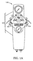
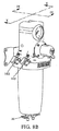
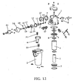
図1A、1Bは、本発明の実施形態に係るフィルタレギュレータ100の正面図および斜視図である。フィルタレギュレータ100の断面図を図2〜図4に示す。図6は、フィルタレギュレータ100の分解図である。図8〜図12は、図1〜図7に示すフィルタレギュレータの簡素化版であるフィルタレギュレータ800の様々な図である。すなわち、フィルタレギュレータ800は、(26のような)管路圧力計や、(29のような)フィルタ交換表示器を何れも含まない。さらに、フィルタレギュレータ800では、フィルタレギュレータ100の弁22、23は手動ドレンコック30、31に置き換えられている。フィルタレギュレータ800はそれ以外はフィルタレギュレータ100と実質上同一であるので、フィルタレギュレータ100および800を以下一緒に詳細に説明する。
1A and 1B are a front view and a perspective view of a
図1Aに示すように、フィルタレギュレータ100はハウジング101を含み、ハウジング101は上部部分または中空本体1と、下部部分またはボウル2とを含む。本体1とボウル2とは、1つの実施形態では、別々に製造し、例えば、図6に示すボルト651によって互いに固定する。また、本体1とボウル2とは、ねじまたはバヨネット接続によって取り付けてもよい。1つの実施形態では、図6のOリング676のようなシール要素を使用して、本体1とボウル2との間の接続を気密的なものにする。上記の脱着式機構によって、保守またはサービスのためボウル2を本体1から取り外すことが可能である。ボウル2および中空本体1は各々、金属、またはプラスチックのような何らかの適切な材料から製造すればよい。しかし、他の構成および/または材料であってもよい。
As shown in FIG. 1A, the
ハウジング101は入口252(図2、9B)を含み、入口252は、1つの実施形態では、ハウジング101の上部部分または本体1に位置する。入口252は圧縮空気のような加圧気体の供給源(図示せず)に接続するように構成されている。入口252と加圧気体の供給源との間の接続は、この技術分野で周知の何らかの種類のものでよく、ここではこれ以上詳細には説明しない。図2、9Bに示す特定の実施形態では、入口252は、フィルタレギュレータ100の後ろ側に配置された上向きの穴である。この機構は、フィルタレギュレータ100の前方の作業領域を大きく妨げることなく、例えば、ホースを介した、加圧気体の供給源から入口252への接続を容易にする。しかし、他の構成であってもよい。
The
ハウジング101はさらに、入口252を介してフィルタレギュレータ100に入り、以下説明するようにフィルタ機構によって濾過された加圧気体が濾過済み加圧気体として提供される少なくとも1つの出口を含む。図1〜図6で開示される特定の実施形態では、ハウジング101の上部部分または本体1に提供された4つの出口102〜104(図1A、1B)ならびに105(図6)が存在する。出口102〜105はフィルタレギュレータ100の対向する横側面に位置し、図9Cに最もよく見られるように、斜め下を向いている。この構成は、出口102〜105に接続されるホース(図示せず)のねじれを回避する。しかし、他の構成であってもよい。さらに、フィルタレギュレータ100の出口の数は4つに制限されず、適用業務に応じて変化してよい。
The
フィルタレギュレータ100の出口102〜105の中で、出口103〜105は、以下説明するように、濾過済み加圧気体が圧力レギュレータによって調整された望ましい圧力で提供される調整出口である。それと対照的に、出口102は、濾過済み加圧気体が、入口252を介して流入する非濾過加圧気体の管路圧またはそれに近い圧力で提供される非調整出口である。別言すれば、非調整出口102の濾過済み加圧気体の圧力は圧力レギュレータによって調整されていない。出口103〜105の調整濾過済み加圧気体は、例えば、塗料スプレーまたは塗料加圧といった、特定の圧力の清潔または濾過済みの加圧気体を必要とする適用業務で使用可能である。ダスターガンのような、濾過済み加圧気体が特定の圧力である必要のない適用業務では、非調整出口102を利用してもよい。ここでも、フィルタレギュレータ100の調整および非調整出口の数は特定の開示された数に制限されず、適用業務に応じて変更してもよい。例えば、全ての出口を調整出口または非調整出口の何れかにしてもよい。後者すなわち全ての出口が非調整出口である場合、圧力レギュレータは省略してもよく、その場合フィルタレギュレータ100は圧力調整を伴わず単純に濾過済み加圧気体を提供するフィルタ装置となる。しかし、他の構成であってもよい。
Among the outlets 102-105 of the
図6に示すように、各出口102〜105は出口を選択的に開閉するための弁653を装備している。1つの実施形態では、図9Cに最もよく見られるように、弁653はボール弁であるが、他の種類の弁を使用してもよい。図6に示すように、各出口102〜105は、それぞれ弁653の主本体およびハンドルと嵌合する複数の穴654、655を含む。しかし、他の構成であってもよい。さらに、1または複数の弁653を省略またはフィルタレギュレータ100と別個に提供してもよく、その場合それぞれの出口102〜105は継手等によって別個に提供された弁(単数または複数)に接続する。
As shown in FIG. 6, each outlet 102-105 is equipped with a
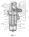
ここで図2に戻ると、フィルタレギュレータ100の内部構造が示される。すなわち、フィルタレギュレータ100は、ハウジング101以外に、入口252を介してフィルタレギュレータ100に入る加圧気体を濾過し、出口102〜105に加圧調整または非調整何れかの濾過済み加圧気体を提供するための、入口252の下流かつ出口102〜105の上流に位置するフィルタ機構256を含む。
Returning now to FIG. 2, the internal structure of the
フィルタ機構256はハウジング101の下部部分またはボウル2内に位置し、一方がもう一方の内部に配置された少なくとも2つのフィルタエレメント4および5を含む。図2の特定の実施形態では、外側フィルタエレメント4が内側フィルタエレメント5の上流に位置しているので、加圧気体は、動作の際、図9Bの矢印で示すように、フィルタエレメント4の後フィルタエレメント5を通じて外側から内側方向に移動し、フィルタエレメント5内の内部空間を通じてハウジング101の上部部分または本体1に逃れる。上流のフィルタ、すなわちフィルタエレメント4は粗目フィルタとして構成し、下流のフィルタ、すなわちフィルタエレメント5は細目フィルタとして構成する。粗目フィルタ4を細目フィルタ5の上流に配置するのは、そうしなければ細目フィルタ5を容易に目詰まりさせるだろう大きなサイズの汚染物質を先に除去するためである。外側のフィルタエレメント4を内側のフィルタエレメント5の下流に配置する逆の構成であってもよいが、この場合は、加圧気体が、動作の際、逆の、内側から外側方向に移動することになるので、いくつかの部品の再配置が必要になるだろう。
特定の実施形態では、粗目フィルタまたはフィルタエレメント4は粒子フィルタまたは多孔性フィルタであり、細目フィルタまたはフィルタエレメント5はコアレッシングフィルタまたはコアレッサである。
In a particular embodiment, the coarse filter or
粒子フィルタ4は、加圧気体からあるサイズの塵埃、錆およびパイプの水垢といった粒子を除去し、こうした粒子が下流のフィルタエレメント、すなわちコアレッシングフィルタ5を詰まらせるのを防止するように構成する。すなわち、粒子フィルタ4は、特にコアレッシングフィルタおよび一般にフィルタレギュレータ100の長い耐用寿命および高効率を保証する前置フィルタとして機能する。粒子フィルタ4は、この技術分野で周知の何らかの方法で構成してよい。例えば、粒子フィルタ4はあるメッシュサイズのメッシュまたは多孔性材料を含んでもよい。1つの実施形態では、粒子フィルタ4は、所定の多孔性が得られるまで互いに圧縮された複数のプラスチックのボールまたは球体を備える。1つの実施形態では、粒子フィルタ4は直径1μm程度の粒子を捕捉または妨害するように構成する。他の構成および/またはメッシュサイズであってもよい。
The
コアレッシングフィルタ5は、粒子フィルタ4を通過した事前濾過済み加圧気体から油および/または水および/または他の液体および/または蒸気を除去するように構成する。また、コアレッシングフィルタ5は、粒子フィルタ4を逃れた微細粒子を捕捉する役目をも果たす。コアレッシングフィルタ5は、この技術分野で周知の何らかの方法で構成してよい。例えば、コアレッシングフィルタ5は、1つの実施形態では、適用業務に応じて1ミクロン以下の直径または数〜数十ミクロン(μm)の直径を有するマイクロファイバでもよい、複数の微細なファイバを備えるファイバ組立体を含んでもよい。こうしたファイバまたはマイクロファイバは、単一層またはいくつかの層に配置したガラスファイバまたはガラスマイクロファイバでもよい。しかし、他の構成および/または材料および/またはファイバサイズであってもよい。
The coalescing
コアレッシングフィルタ5は一般に、固体汚染物質を直接インパクトおよび/または妨害モードで除去し、液体汚染物質を拡散モードで除去する。すなわち、特定のサイズおよび/または質量の固体汚染物質(すなわち、粒子フィルタ4を逃れた微細粒子)は、コアレッシングフィルタ5で使用されるファイバまたは他のフィルタ媒体と衝突してそれに付着する。事前濾過済み加圧気体の流れがコアレッシングフィルタ5を通過する時やはりファイバまたはフィルタ媒体に衝突する液体または蒸気汚染物質、例えばエアロゾル、は、ファイバまたはフィルタ媒体に永続的には付着しない。むしろ、エアロゾルは、重力によりファイバに沿って下降する際に互いに結合して大きな滴を形成する。この滴は成長し、その質量によって、コアレッシングフィルタ5のファイバまたはフィルタ媒体(単数または複数)から脱落するようになり、実質上排流される。
The coalescing
図2に示すように、コアレッシングフィルタ5は内側支持層またはコア257と外側フィルタ媒体258とを含む。フィルタ媒体258が外側にあり支持層257が内側にある、または、支持層257の内外両方の側に多数のフィルタ媒体258が提供される、または、1または複数のフィルタ媒体258の内外両方の側に多数の支持層257が提供される、といった代替的構成も可能である。
As shown in FIG. 2, the coalescing
支持層257は、コアレッシングフィルタ5全体に機械的強度を提供するように構成する。1つの実施形態では、支持層257は有孔スリーブとして構成する。支持層257のための適切な材料は、ステンレス鋼のような金属を含む。しかし、他の構成および/または材料であってもよい。
The support layer 257 is configured to provide mechanical strength to the entire coalescing
上述のように、外側フィルタ媒体(単数または複数)258は、1または複数のファイバ層を含んでもよい。ファイバ層は平滑なものでもよくまた襞のあるものでもよい。また、フィルタ媒体(単数または複数)258は、凝集した液体、例えば、油または水、の排流を促進するための、疎水性でもよい、排流層を含むかまたはそれによって被覆してもよい。1つの実施形態では、フィルタ媒体258は直径0.1ミクロン程度の液滴および粒子を95%程度またはそれより高い効率で除去するように構成する。ここでも、他の構成および/または材料および/またはフィルタサイズおよび効率であってもよい。
As described above, the outer filter media (s) 258 may include one or more fiber layers. The fiber layer may be smooth or wrinkled. Also, the filter media (s) 258 may include or be covered by a drainage layer that may be hydrophobic to facilitate drainage of the agglomerated liquid, such as oil or water. . In one embodiment, the
図6に示すように、フィルタエレメント4およびフィルタエレメント5は互いに分離可能であり、個別に点検および/または交換可能である。しかし、フィルタレギュレータ100の組立を容易にし、かつ/または、フィルタ機構256全体を交換する時濾過済み加圧気体の望ましい品質または清浄度を保証するため、フィルタエレメントを単一のフィルタカートリッジ内に一体的に製造してもよい。別の実施形態では、フィルタ機構256は2つより多いフィルタエレメントを含んでもよいことに注意されたい。フィルタエレメントは必ずしも、図2〜図6に具体的に開示したような円筒形の形状ではない。むしろ、フィルタエレメントの1つまたはいくつかまたは全ては円錐形または円錐台形の形状を有してもよい。フィルタエレメントは円形断面である必要はなく、正方形、六角形、等のような他の断面形状を有してもよい。
As shown in FIG. 6, the
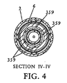
図2に示す実施形態によれば、フィルタ機構256は、フィルタエレメント4、5の下端を受けるための、図6に最もよく見られる単一またはいくつかの溝を有する底部プレート7によって、下から支持されている。溝(単数または複数)は、フィルタレギュレータ100の組立のため、フィルタエレメント4、5を一時的に定位置に固定する。底部プレート7はさらに、コアレッシングフィルタ5によって凝集した液体の排流のための少なくとも1つの貫通穴359を含む。図3〜図4には4つの貫通穴359を示すが、底部プレート7には何らかの他の数の貫通穴を提供してもよい。図2の実施形態では、貫通穴359はフィルタエレメント4および5の間の空間に対応して配置されている。しかし、他の構成であってもよい。例えば、貫通穴359はコアレッシングフィルタ5の下および/または半径方向内側に提供してもよい。底部プレート7は、プラスチックおよび/または金属といった何らかの適切な材料から製造してよい。1つの実施形態では、底部プレート7は、フィルタエレメント4、5を位置決めするための溝(単数または複数)を画定するプラスチック製のディスクと、以下詳細に説明するように棒8に確実に接続するための、このディスクの中心の金属、例えば真鍮、の部材とを含む。他の構成および/または材料であってもよい。
According to the embodiment shown in FIG. 2, the
カップ6は底部プレート7の下に配置され、貫通穴359を通過した凝集液体を収集する。図6に最もよく見られるように、カップ6は上部の拡大した部分660と下部の細い部分661とを含む。カップ6の上部の拡大した部分660は底部プレート7を密閉式に受けるように構成する。カップ6と底部プレート7との間のシールのためにOリング662を使用してもよい。1つの実施形態では、カップ6の下部の細い部分661は漏斗の形状を有する。しかし、他の形状であってもよい。
The
下部の細い部分661は、カップ6に収集された凝集液体を排流するため、カップ6の底部の開口363(図3)を有する。下部の細い部分661は、ボウル2の底部の穴364に密閉式に嵌合する。図3の実施形態では、下部の細い部分661と穴364との間を密閉するための別途のOリングは必要ない。例えば、下部の細い部分661の外壁および/または穴364の内壁は、穴364の中で下部の細い部分661を摩擦的に保持し要素間を密閉する弾性リブを含んでもよい。カップ6は、金属またはプラスチックといった、何らかの適切な材料から製造してよい。カップ6がプラスチック製である場合、下部の細い部分661の外壁の弾性リブはカップ6の残りの部分と一緒に成形してよく、そのように製造したカップ6はボウル2の底部で穴364に圧入してよい。カップ6とボウル2との間を密閉するためOリングを使用するといった他の構成であってもよい。
The lower
1つの実施形態では、カップ6とボウル2の内壁とは、図2〜図3に最もよく見られるように、カップ6をボウル2の底部の穴364に十分に押し付けると係合してカップ6がそれ以上穴364に押し付けられるのを止める相フランジを含む。上述のように、ボウル2の穴364とカップ6の下部の細い部分661とは密閉式に接触しているかまたは相互間の密閉要素を有する。しかし、ボウル2の内側側壁、例えば372(図3)、とカップ6の外側側壁、例えば673(図6)とは全体が密閉式に接触しているわけではない。一部の実施形態では、カップ6は外側側壁673に1つかそれより多い切り欠き部分を含むことさえある。その結果、カップ6の上のボウル2の内側側壁372とフィルタエレメント4との間に位置する空間374(図3)と、カップ6の下に位置する空間375(図3)との間に流通が存在する。後で説明するように、この流通によって、水または液滴および、時には、固体粒子がボウル2の内側側壁372に沿って流れ、カップ6を通過して空間375に集まり排流されるようになる。
In one embodiment, the
カップ6の底部の開口363の内部には、弁23が提供され、開口363を選択的に開閉する。弁23は自動弁またはドレンコックでよい。図2の実施形態では、弁23は、下部の細い部分661内の凝集液体が所定のレベルに達すると自動的に開くフロート型自動弁である。図8B、9に示すように、手動弁またはドレンコックを代わりに使用してもよい。電子式自動弁のような他の種類の弁であってもよい。
A
図2、3に最もよく見られるように、フィルタ機構256の上端には、デフレクタ3が配置されている。図6の665に最もよく見られるように、デフレクタ3はその縁端の周囲にフィンを有する。後で説明するように、フィン665はフィルタ機構256の軸方向および/または入口252の軸方向に対して傾斜しており、入口252を通じてハウジング101に入る加圧気体の流れに渦流運動を付与する。デフレクタ3は、図6に開示するように一般に円形の形状でもよく、また関連米国仮特許出願第60/734574号で開示されているように円筒形のスカートを含んでもよい。一般に、デフレクタ3は固定式であり、フィルタレギュレータ100内の加圧気体の流れにかかわらず回転しない。
As best seen in FIGS. 2 and 3, the
1つの実施形態では、デフレクタ3は、フィルタエレメント4および/または5の上端に合致する下側の溝によって、フィルタエレメント4、5の一方及び/または両方の上部に自然に位置決めされる。さらなる実施形態では、キャップ266(図2)を使用してデフレクタ3をフィルタ機構256の上部の中心に置く。すなわち、図2に示すように、キャップ266は、一方でデフレクタ3の中心穴に嵌合し、もう一方でフィルタエレメント5の上端に嵌合する。キャップ266および/またはデフレクタ3は底部プレート7として機能し、フィルタレギュレータ100を組立てる前にフィルタ機構256を一時的に定位置に固定する。また、キャップ266および/またはデフレクタならびに底部プレート7は、フィルタ機構256のフィルタエレメント4、5の間の望ましい間隔を維持する役目も果たす。
In one embodiment, the
穴364以外に、ボウル2はさらに、以下さらに説明するように、デフレクタ3が加圧気体の流れに付与する渦流運動によって収集された水または他の液体を排流する、底部の別の穴369(図3)を含む。穴364および開口363と同様、穴369も、収集された液体または水を選択的に排流するための弁22(図3)または30(図10)を装備している。
In addition to
固定ロッド8が提供され、底部プレート7をハウジング101の上部部分または中空本体1に固定して、フィルタ機構256をデフレクタ3およびキャップ266(もしあれば)と一緒に締め付ける。詳しく言うと、図2の実施形態では、ロッド8は、それぞれ底部プレート7および中空本体1のねじ穴267、268に脱着式にねじ込まれる2つのねじ付き端部を含む。バヨネット接続のような、他の接続形式を、ロッド8の何れかまたは両方の端部で使用してもよい。ロッド8を底部プレート7および中空本体1の何れかと一体的に製造してもよい。ロッド8をねじまたは他の方法で底部プレート7の穴267に脱着式に接続する1つの実施形態では、接続の望ましい機械的強度を保証するため、こうした穴267は底部プレート7の中央の金属、例えば真鍮、の部材に提供される。この場合、底部プレート7は真鍮部材の周囲にプラスチックのディスク部分を成形することによって形成してもよい。
A securing
1つの実施形態では、図6の670、671のようなOリングを使用して、フィルタエレメント4および底部プレート7の上端でフィルタエレメント4とデフレクタ3との間をシールする。図6はフィルタエレメント5とデフレクタ3および底部プレート7との間にはOリングまたは他のシール要素を開示していないが、こうしたOリングまたはシール要素も他の実施形態にしたがって提供してよい。
In one embodiment, an O-ring such as 670, 671 in FIG. 6 is used to seal between the
さらに、図6はキャップ665とデフレクタ3とを中空本体1から離れたものとして開示しているが、実施形態によっては、部品点数を減らすため、これらの要素を中空本体1と一体的に製造してもよい。代替実施形態では、キャップ665だけを中空本体1と一体的に製造し、デフレクタ3は別個の要素として製造する。しかし、他の構成であってもよい。
Further, FIG. 6 discloses the
以下、上述のフィルタレギュレータ100のフィルタ部分の動作を図9B〜図9Dを参照して説明する。
Hereinafter, the operation of the filter portion of the above-described
図9Bの矢印Aによって示すように、圧縮空気のような加圧気体の流れは、入口252を通じてフィルタレギュレータ100または800に入る。図9Bの矢印Bによって示すように、加圧気体の流れはデフレクタ3によって誘導され渦流パターンをなす。加圧気体中に含まれる水、油または他の液体および、破片のような何らかの固体汚染物質は、渦流運動によって発生した遠心力の結果加圧気体の流れから分離され、その遠心力によってボウル2の内側側壁372に押し付けられる。分離された固体汚染物質、水、油または他の液体はボウル2の内側側壁372に沿って滑り落ち、カップ6を通過してカップ6の下の空間375に集まる。すなわち、カップ6は、ボウル2の底部に静領域、すなわち空間375、を形成し、渦流をなす加圧気体の流れがボウル2の底部に収集された固体汚染物質、水、油または他の液体に達するのを防止するバッフルとして機能する。この方法で、蓄積した汚染物質(固体および/または液体)は、最終的に渦流をなす加圧気体の流れから除去されて、渦流をなす加圧気体の流れに同伴または再同伴して戻ることなくボウル2の底部に残り、こうした蓄積された汚染物質はドレンコック30または自動ドレン22を介してボウル2から除去されるに至る。
A flow of pressurized gas, such as compressed air, enters the
空間374中の渦流をなす加圧気体の流れは引き続き、大部分の固体粒子を除去するフィルタエレメント4を通過する。フィルタエレメント4を通過した渦流をなす加圧気体の流れは、事前濾過済み加圧気体の流れとしてフィルタエレメント4および5の間の空間に入る。
The flow of pressurized gas forming a vortex in
そして、事前濾過済み加圧気体の流れは引き続き、フィルタエレメント4を通過した微細固体粒子ならびに、例えば水、油または他の液体の液滴および/またはそれらの蒸気といった液体粒子を捕捉するフィルタエレメント5を通過する(図9Bの矢印C)。捕捉された液滴は結合または凝集した後重力によってフィルタエレメント5の下端に下降し、そこで凝集した水、油または液体は底部プレート7の穴359を通過してカップ6の底部セクションに至る。
The pre-filtered pressurized gas flow then continues to filter
底部プレート7は、カップ6の底部に第2の静領域378を形成し、事前濾過済み加圧気体の流れが、カップ6の底部に収集された汚染物質および凝集した水、油または他の液体に到達するのを防止する。蓄積した汚染物質は、加圧気体の流れに同伴または再同伴して戻ることなくカップ6の底部に残り、ドレンコック31または自動ドレン23を介してカップ6から除去されるに至る。
The
静領域375は、カップ6の底部セクションの側壁、例えば679(図6)、によって静領域378から分離されていることに注意されたい。すなわち、静領域中の固体または液体何れかの汚染物質は、フィルタエレメント4を介する圧力降下による異なる圧力下にあるため、混ざり合うことはない。その結果、静領域375内の汚染物質が、圧力の低い静領域378を介して空間374内の事前濾過済み加圧気体の流れに同伴または再同伴して戻る可能性はない。
Note that the
フィルタエレメント5を通過した清潔な、濾過済み加圧気体はフィルタエレメント5の内部空間380(図3、9B)に入り、図9Bの矢印Dが示すように、上向きに流れて中空本体1の内部に入る。フィルタレギュレータ100または800が濾過目的専用、すなわち圧力調整を伴わずに構成されている場合、濾過済み加圧気体は、この場合非調整出口である出口102〜105に直接供給され、その後、対応する弁653が開いている時に加圧気体によって動作する接続先の外部装置に供給される。しかし、圧力調整が望ましい場合、281(図2)のような圧力レギュレータが必要である。
The clean, filtered pressurized gas that has passed through the
圧力レギュレータ281は、この技術分野で周知の何らかの方法で構成してよい。
The
図2および図9B〜図9Dの特定の実施形態では、圧力レギュレータ281は、中空本体1の内部を2つのチャンバ、すなわち上流チャンバ283(図9Cにも図示)と下流チャンバ(図9Dにも図示)とに分離する弁282を含む。上流チャンバ283はフィルタエレメント5の内部空間380と流通し、そこから濾過済み加圧気体を受け取る。また、図9Cに最もよく見られるように、上流チャンバ283は非調整出口102とも流通する。上流チャンバ283内の圧力は調整されていないので、上流チャンバ283は非調整チャンバであり、非調整濾過済み加圧気体が非調整出口102に提供される。他方、下流チャンバ284は調整チャンバであって、その圧力は圧力レギュレータ281によって調整されている。図9Dに最もよく見られるように、下流チャンバ284は調整出口103〜105と流通しており、調整濾過済み加圧気体が調整出口103〜105に提供される。
In the particular embodiment of FIGS. 2 and 9B-9D, the
弁282は弁棒10と弁座11とを含む。図2の特に開示する実施形態では、弁座11は、ナット12の端部の上に置かれる柔軟な部材またはシールであり、ナット12は中空本体1の内壁のねじ付きくぼみにねじ込まれる。ばね9が提供され、弁座11に対して弁棒10にバイアスをかけ、流れがない時弁282を閉じるようにする。ナット12を提供することによって弁282の組立が容易になっており、組立の際は、ばね9、弁棒10および弁座11を中空本体1内の受け入れキャビティ内に配置した後ナット12を受け入れくぼみにねじ止めして弁282を定位置に固定する。
The valve 282 includes a
弁棒10はさらにナット12およびディスク15と一線にある中央開口を通じて延び、隔膜14の中央部分685(図6)の貫通穴689(図6)の開口(図9の右側の開口)と係合する。弁棒10の先細または丸みのある端部938は貫通穴689の図9Bの右側の開口の周囲の表面に置かれるので、貫通穴689を有する中央部分685が(図9Bの)右側に移動すると、弁棒10もばね9の作用に反して(図9Bの)右側に移動する。貫通穴689の(図9Bの)右側の開口は普通、弁棒10とOリングまたはシール要素24とによって密閉されている。しかし、弁棒10は貫通穴689または中央部分685または隔膜14の何らかの他の部分に堅固に固定されてはいない。すなわち、貫通穴689を有する中央部分685が(図9Bの)右側に移動しても、弁棒10は一緒に移動しない。その結果、貫通穴689の(図9Bの)右側の開口はシール要素24と弁棒10の先細または丸みのある端部938との間の隙間の分だけ開くことができる。1つの実施形態では、隔膜14の中央部分685は金属または硬質プラスチックといった剛性の材料から製造し、その周辺部分686(図6)はゴム、ゴム引き布または布補強ゴムといった変形可能な材料から製造する。さらなる実施形態では、周辺部分686は弾性変形可能である。しかし、他の構成および/または材料であってもよい。
The valve stem 10 further extends through a central opening in line with the
ばねハウジング16が、例えばボルト687(図6)によって中空本体1に固定されると、隔膜14の周辺部分686はディスク15のリムとばねハウジング16との間に緊密に締め付けられる。ばねハウジング16と中空本体1との間の他の接続形式、例えばねじ接続を使用してもよい。こうした構造の結果、隔膜14の中央部分685と、ひいては弁棒10は、隔膜14の周辺部分686の可撓性により、静止位置の前後に移動可能である。ディスク15は隔膜14についての隔膜チャンバ939(図9B)を画定するので、圧力レギュレータ281を通過する濾過済み加圧気体の主流との隔膜14の物理的接触は大きく減少する。したがって、隔膜14の耐用寿命期間を延長することができる。隔膜チャンバ939は、ディスク15内に形成されたオリフィス688(図6)によって下流チャンバ284と流通する。
When the
調節ばね17がばねハウジング16内に提供され、圧縮されると、隔膜14の中央部分685にばね力を及ぼす。調節ばね17のばね力は、ピン20を介して調節ねじ19に係合するノブ21によって調節する。調節ナット18は調節ばね17の端部に配置され、調節ねじ19とねじ係合する。ノブ21を回転させると、調節ねじ19も回転して、調節ナット18が調節ばね17を圧縮または解放する。本発明は圧力レギュレータ281の上述の構成に制限されず、他の構成であってもよい。
When the
以下、上述のフィルタレギュレータ100の圧力調整部の作用を説明する。
濾過済み加圧気体は、フィルタエレメント5の内部空間380から上流チャンバ283に供給される。上流チャンバ283内の濾過済み加圧気体の圧力はまだ調整されていないので入口252の上流の管路圧と共に変動することがある。上流チャンバ283内の濾過済み加圧気体の非調整圧力は、ばね9と共に弁棒10を弁座11に押し付けて、弁282を閉じる。濾過済み加圧気体は下流チャンバ284およびその調整出口103〜105に提供されない。しかし、非調整濾過済み加圧気体は、上流チャンバ283の非調整出口102で利用可能である。
Hereinafter, an operation of the pressure adjusting unit of the above-described
The filtered pressurized gas is supplied from the
ノブ21を、例えば時計回り方向に、回転させて圧力レギュレータ281の設定値を望ましい出力調整圧力に調節すると、調節ばね17が図2の左側(図9Bの右側)に移動する。その後隔膜14が弁棒10と共に図2の左側(図9Bの右側)に移動して、弁棒10を弁座11から離し弁282を開く。図9Bの矢印Eによって示すように、濾過済み加圧気体は、弁座11の中央開口を通じて弁棒10の周囲を流れ、下流チャンバ284に入る。そして、濾過済み加圧気体は調整出口103〜105で利用可能となる。
When the
下流チャンバ284はディスク15のオリフィス688を通じて隔膜チャンバ939と流通するので、調節ばね17の作用に反して働く隔膜チャンバ939内の圧力は下流チャンバ284内の圧力と共に増大して、増大する力を隔膜14の左側に印加する。貫通穴689の(図9Bの)右側の開口はシール要素24によって密閉され、隔膜チャンバ939内の圧力を増大することに注意されたい。隔膜14および弁棒10は図2の右側(図9Bの左側)に徐々に移動して、調節ばね17を圧縮する。下流チャンバ284内の圧力、すなわち、隔膜チャンバ939内の圧力が調節ばね17のばね力と均衡すると、隔膜14および弁棒10の移動は停止する。1または複数の調整出口103〜105が開いていれば、隔膜14および弁棒10は均衡位置に留まり弁282の開状態を維持するので、開いた調整出口103〜105では望ましい、または調整された圧力の濾過済み加圧気体の連続供給が保証される。調整出口103〜105が全て閉じている場合、弁282が閉じると力の均衡が発生する。ここで、下流チャンバ284内の圧力は、ノブ21で調整した望ましいレベルになる。
Since the
ノブ21を反対方向、すなわち反時計回り方向に回転させて調整出口103〜105を閉じ調整圧力を下げた後、下流チャンバ284および隔膜チャンバ939内に捕捉された濾過済み加圧気体を解放することができる。すなわち、ノブ21を反時計回り方向に回転させて調節ばね17の圧縮力を除去すると、下流チャンバ284および隔膜チャンバ939内に捕捉された濾過済み加圧気体の圧力によって隔膜14は(図9Bの)左側に移動する。弁棒10がナット12およびシール要素11によって止められると、隔膜14が保持するシール要素24は弁棒10に対して弁棒10の先細端部938に対応する位置に移動し、その位置で貫通穴689の(図9Bの)右側の開口が開いて、捕捉された濾過済み加圧気体を、隔膜チャンバ939および下流チャンバ284から、隔膜14の中央穴689を通じてばねハウジング16の内部に逃がし、その後外部に排気する。
Release the filtered pressurized gas trapped in the
電子圧力レギュレータのような、他の種類の圧力レギュレータも、本発明の他の実施形態にしたがって使用してよい。 Other types of pressure regulators, such as electronic pressure regulators, may also be used in accordance with other embodiments of the present invention.
下流チャンバ284内の圧力は、中空本体1の前側に設置した圧力計27によって表示される。圧力計27は、この技術分野で周知の何らかの種類の圧力計でよい。1つの実施形態では、圧力計27は、中空本体1に形成した穴690(図6)にシール691を介してねじで設置する。
The pressure in the
同様に、管路圧、または空間374内の圧力は、中空本体1の前側に設置した圧力計26によって表示される。圧力計26は、この技術分野で周知の何らかの種類の圧力計でよい。1つの実施形態では、圧力計26はボウル2の側壁に形成した穴692(図6)にねじで設置する。
Similarly, the line pressure or the pressure in the
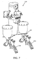
実施形態によっては、図7に示すように、フィルタレギュレータ100はさらに、1または複数のスプレーまたはダスターガンを吊り下げるためボウル2の底部に設置したブラケット28を含む。図7のガン794、793は、この技術分野で周知の何らかの種類のスプレーガンでよい。ガン793、794の例は、その全体を引用によって本出願の記載に援用する、米国特許出願第2003/0230636号で提供されている。
In some embodiments, as shown in FIG. 7, the
さらなる実施形態では、フィルタレギュレータ100は、フィルタ機構256の1つまたは一部または全てのフィルタエレメントの交換が必要な時を表示するための、中空本体1の側面に設置したフィルタ交換表示器29を含む。図5A、5Bの特に開示する実施形態では、フィルタ交換表示器29は、フィルタ機構全体またはフィルタカートリッジ256の交換が必要な時を表示する。
In a further embodiment, the
図5Bのフィルタ交換表示器29は管路圧と濾過済み加圧気体の圧力との間の圧力差によって駆動される。図5Bに示すように、フィルタ交換表示器29は、ピストン597のような可動隔壁によって分離された第1のチャンバ595と第2のチャンバ597とを含む。ピストン597の代わりに、隔膜または他の要素を使用してもよい。第1のチャンバ595は空間380または中空本体1の上流チャンバ283と流通し、濾過済み加圧気体の圧力を有する。第2のチャンバ596は入口252または空間374と流通し、管路圧を有する。ピストン597に作用する圧力差は図5Bの左側を向いており、フィルタ機構256を介する圧力差に対応する。ピストン597は、ピストン597に図5Bの右側へのバイアスをかける圧縮ばね598の作用によって図5Bに示す後退位置に維持される。フィルタ機構256、特にフィルタエレメント4が目詰まりすると、フィルタ機構256を介する圧力降下が増大する。ピストン597の右側に作用する力も増大する。フィルタ機構256の目詰まりが許容できないレベルに達する、すなわち、フィルタ機構256を介する圧力降下が十分に大きくなると、ピストン597の右側に作用する力がばね598のばね力より大きくなって、ピストン597を図5Bの左側に移動させる。その結果、ピストン597の外側端部599が突出し、フィルタ機構256の点検または交換が必要なことを表示する。第1のチャンバ595と第2のチャンバ596とを374、380、377等といったそれぞれの空間に接続することによって、フィルタ交換表示器29をフィルタ機構256中の各フィルタエレメントの目詰まり状態を個別に表示するように構成することもできる。フィルタ交換表示器を何個か提供してもよい。
The
図1〜図7を参照して上記で開示した実施形態はいくつかの利点を有する。すなわち、前面の圧力調節ノブ(21)、フィルタレギュレータの背面の垂直入口(252)、調整および非調整両方の清潔な加圧気体を提供する4つの下向きに傾斜した出口(102〜105)、および内蔵された圧力計(26、27)の構成は独特である。従来のフィルタレギュレータでは、入口は側面にあり、1つの調整出口だけが提供され、圧力調節ノブはフィルタレギュレータの上部にあり、圧力計は露出している。 The embodiment disclosed above with reference to FIGS. 1-7 has several advantages. A front pressure adjustment knob (21), a vertical inlet (252) on the back of the filter regulator, four downwardly inclined outlets (102-105) that provide both regulated and unregulated clean pressurized gas, and The configuration of the built-in pressure gauge (26, 27) is unique. In conventional filter regulators, the inlet is on the side, only one regulating outlet is provided, the pressure adjustment knob is on the top of the filter regulator, and the pressure gauge is exposed.
さらに、一方がもう一方の内側にあるフィルタエレメント4および5の構成も独特である。フィルタエレメントは同軸または同心でよいが、偏心配置することもできよう。従来のフィルタレギュレータでは、フィルタエレメント4および5は別個のボウル内に設置され、開示した実施形態に係る二種一体化構成のフィルタ機構256を提供しない。
Furthermore, the construction of the
さらに、管路圧を表示する圧力計26を中空本体1の壁の上に直接設置したことは有利である。従来のフィルタレギュレータでは、フィルタレギュレータの外部の、普通送気管に設置した独立した圧力計が管路圧を表示している。
Furthermore, it is advantageous to install a
さらに、カップ6のような水または液体を収集する部片を提供しているため、有利にも2つの独立したチャンバ(375、378)の2つのドレン(22、23)を単一のボウル(2)内に配置することが可能になっている。従来のフィルタレギュレータでは、ボウル内に配置されるのは1つのドレンだけである。
Furthermore, the provision of a piece of water or liquid collection, such as
さらに、弁253を中空本体1に組み込む構成は新規である。従来のフィルタレギュレータでは、弁はフィルタレギュレータから独立しており継手によって接続されている。
Furthermore, the structure which incorporates the valve 253 in the hollow
さらに、既知のフィルタレギュレータでガン設置ブラケットを提供するものはない。
開示する実施形態はスプレー塗装に特に適しているが、他の用途にも適用可能である。
Furthermore, no known filter regulator provides a gun mounting bracket.
The disclosed embodiments are particularly suitable for spray coating, but are applicable to other applications.
以上、実施形態の説明によって本発明を例示し、実施形態をかなり詳細に開示したが、添付の請求項の範囲をこの詳細に限定または何らかの意味で制限することを出願人は意図しない。添付の請求項によって定義される説明した実施形態の範囲から離れることなく、さらなる利点および修正を行うことができる。さらに、説明した実施形態の要素が単数形で記載または請求されていることがあるが、単数に制限すると明示的に述べられていない限り、複数も考慮される。 Although the invention has been illustrated by way of example in the foregoing description and disclosed in considerable detail, the applicant does not intend to limit the scope of the appended claims to this detail or in any way. Further advantages and modifications may be made without departing from the scope of the described embodiments as defined by the appended claims. Further, although elements of the described embodiments may be described or claimed in the singular, the plural is also contemplated unless expressly stated to be limited to the singular.
1 上部部分または中空本体
2 下部部分またはボウル
3 デフレクタ
4 フィルタエレメント
7 底部プレート
22 弁
23 弁
26 管路圧力計
29 フィルタ交換表示器
30 手動ドレンコック
31 手動ドレンコック
100 フィルタレギュレータ
101 ハウジング
102 出口
103 出口
104 出口
105 出口
252 入口
372 内側側壁
375 空間
651 ボルト
665 キャップ
670 Oリング
671 Oリング
676 Oリング
800 フィルタレギュレータ
DESCRIPTION OF
Claims (28)
入口と少なくとも1つの出口とを有するハウジングと、
前記ハウジング内の、前記入口の下流かつ前記出口の上流に配置され、前記入口を通じて前記ハウジングに入る加圧気体を濾過して前記出口に濾過済み加圧気体を提供するフィルタ機構とを備え、
フィルタ機構が第1と第2の筒状フィルタエレメントを備え、第1のフィルタエレメントが第2のフィルタエレメント内に配置されるフィルタ装置。 A filter device,
A housing having an inlet and at least one outlet;
A filter mechanism disposed in the housing downstream of the inlet and upstream of the outlet and filtering pressurized gas entering the housing through the inlet to provide filtered pressurized gas to the outlet;
A filter device in which the filter mechanism includes first and second cylindrical filter elements, and the first filter element is disposed in the second filter element.
前記第1と第2のフィルタエレメントを下から支持する、排流目的で前記第1と第2のフィルタエレメントの間の空間に対応する少なくとも1つの貫通穴を内部に有する底部プレートを備える請求項3に記載のフィルタ装置。 further,
A bottom plate supporting the first and second filter elements from below and having at least one through-hole therein corresponding to a space between the first and second filter elements for drainage purposes. 4. The filter device according to 3.
第1のフィルタエレメントによって加圧気体から濾過された汚染物質を内部に収集するため底部プレートの貫通穴の下に配置されたカップと、
汚染物質を制御下で除去するための、前記カップの底部の制御開口とを備える請求項4に記載のフィルタ装置。 further,
A cup disposed under the through hole in the bottom plate for collecting therein the contaminants filtered from the pressurized gas by the first filter element;
5. A filter device according to claim 4, comprising a control opening at the bottom of the cup for controlled removal of contaminants.
前記カップの底部が第1の排流穴でハウジングと係合し、それによってカップ内から、前記カップの底部の制御開口と第1の排流穴とを通じて、前記ハウジングの外部に汚染物質を制御下で除去することが可能になる請求項5に記載のフィルタ装置。 The housing further comprises a first outlet hole in a lower portion thereof;
The bottom of the cup engages the housing at a first drain hole, thereby controlling contaminants from within the cup to the outside of the housing through a control opening at the bottom of the cup and the first drain hole. 6. A filter device according to claim 5, which can be removed underneath.
制御開口が、汚染物質を自動または手動で除去するため第1の弁と嵌合する請求項6に記載のフィルタ装置。 The bottom of the cup extends through the first drainage hole;
The filter device of claim 6, wherein the control opening mates with the first valve for automatic or manual removal of contaminants.
第2のフィルタエレメントの上流かつ入口の下流に配置されたデフレクタを備え、
前記デフレクタが、入口を通じて前記ハウジングに入る加圧気体の流れに渦流運動を付与するため、前記フィルタエレメントの軸方向に対して傾斜して延びる複数の軸方向フィンを有する請求項7に記載のフィルタ装置。 further,
A deflector disposed upstream of the second filter element and downstream of the inlet;
8. A filter according to claim 7, wherein the deflector comprises a plurality of axial fins extending obliquely with respect to the axial direction of the filter element to impart vortex motion to the flow of pressurized gas entering the housing through an inlet. apparatus.
第2のフィルタエレメントによって加圧気体から濾過され、また渦流運動のためハウジングの側壁に押し付けられ、その後前記ハウジングの下部部分に収集される汚染物質を自動または手動で除去するため、第2の排流穴が第2の弁と嵌合する請求項8に記載のフィルタ装置。 The housing further comprises a second outlet hole in a lower portion thereof;
In order to automatically or manually remove the contaminants filtered from the pressurized gas by the second filter element and pressed against the side wall of the housing for vortex motion and then collected in the lower part of the housing, The filter device according to claim 8, wherein the flow hole is fitted with the second valve.
前記第2のフィルタエレメント内を軸方向に延びる棒を備え、
前記棒が、それぞれハウジングの上部部分と底部プレートとに接続された対向する上部および下部の端部を有し、
前記棒の上部および下部の端部と前記ハウジングおよび底部プレートのうち対応する一方との接続の少なくとも1つが可動式であるため、フィルタ機構を前記ハウジング内に脱着式に固定することが可能になる請求項9に記載のフィルタ装置。 further,
A rod extending axially within the second filter element;
The bar has opposing top and bottom ends connected to the top and bottom plates of the housing, respectively;
Since at least one of the connections between the upper and lower ends of the rod and the corresponding one of the housing and the bottom plate is movable, the filter mechanism can be removably secured within the housing. The filter device according to claim 9.
前記キャップと前記デフレクタとが、その中を通じて前記棒が延びる環状形状を有し、
前記棒の上端および下端が接続される時、前記フィルタ機構と前記キャップとがハウジングの上部部分と前記底部プレートとの間に脱着式に締め付けられる請求項10に記載のフィルタ装置。 Furthermore, a cap for detachably fixing the deflector to the upper end of the filter mechanism is provided,
The cap and the deflector have an annular shape through which the rod extends;
11. The filter device according to claim 10, wherein when the upper end and the lower end of the bar are connected, the filter mechanism and the cap are detachably clamped between the upper portion of the housing and the bottom plate.
前記ハウジングの上部部分の、前記フィルタ機構の下流かつ前記少なくとも1つの出口の上流に配置され、圧力レギュレータの設定にしたがって濾過済み加圧気体の圧力を調整し、前記少なくとも1つの出口に調整濾過済み加圧気体を提供する圧力レギュレータを備える請求項1に記載のフィルタ装置。 A filter regulator,
Located in the upper part of the housing, downstream of the filter mechanism and upstream of the at least one outlet, adjusts the pressure of the filtered pressurized gas according to the setting of the pressure regulator, and is adjusted and filtered at the at least one outlet The filter apparatus of Claim 1 provided with the pressure regulator which provides pressurized gas.
前記少なくとも1つの出口が、調整チャンバの壁に形成された1または複数の調整出口を備え、
前記フィルタ装置がさらに、前記非調整チャンバの壁に形成された、非調整出口に非調整濾過済み加圧気体を提供する非調整出口を備える請求項12に記載のフィルタ装置。 The upper portion of the housing comprises a non-regulating chamber and a regulating chamber separated by a valve of the pressure regulator;
The at least one outlet comprises one or more adjustment outlets formed in a wall of the adjustment chamber;
13. The filter device of claim 12, further comprising a non-regulated outlet formed in a wall of the non-regulated chamber for providing a non-regulated filtered pressurized gas to the non-regulated outlet.
設定を手動で調節するための前記圧力レギュレータの圧力調節制御装置がハウジングの上部部分の前面に配置され、
前記調整および非調整出口がハウジングの上部部分の対向する横側面に配置され斜め下向きである請求項13に記載のフィルタ装置。 The inlet is located on the back of the upper portion of the housing and is facing upward;
A pressure regulation control device of said pressure regulator for manually adjusting the setting is arranged in front of the upper part of the housing;
14. The filter device of claim 13, wherein the adjusted and non-adjusted outlets are disposed on opposite lateral sides of the upper portion of the housing and are obliquely downward.
前記少なくとも1つの圧力計が前記ハウジングのそれぞれ上部または下部部分の前側に設置される請求項15に記載のフィルタ装置。 And at least one pressure gauge that is received in a port formed in at least one of the upper and lower portions of the housing and measures the pressure of at least one of the unregulated filtered pressurized gas and the regulated filtered pressurized gas. With
The filter device according to claim 15, wherein the at least one pressure gauge is installed on a front side of each upper or lower portion of the housing.
前記ブラケットが、濾過済み加圧気体を受け取るため調整および非調整出口の一方に接続可能なスプレーまたはダスターガンを受け入れて保持する少なくとも1つの、くぼみまたは溝を備える請求項16に記載のフィルタ装置。 Furthermore, a bracket installed at the bottom of the lower part of the housing,
The filter device of claim 16, wherein the bracket comprises at least one indentation or groove for receiving and holding a spray or duster gun connectable to one of the regulated and non-regulated outlets for receiving filtered pressurized gas.
前記圧力レギュレータがさらに、前記圧力レギュレータの設定を調節する圧力調節制御装置を備え、
前記圧力調節制御装置が、前記弁頭および弁座の一方の前記閉位置からの変位を発生しすることによって、前記弁を開き、濾過済み加圧気体が非調整チャンバから調整チャンバに入るようにするよう調節可能であり、
調整チャンバ内の圧力が、圧力調節制御装置の調節に対応して望ましいレベルに達すると、前記弁頭および弁座が閉位置に戻る請求項13に記載のフィルタ装置。 The pressure regulator valve includes a valve seat and a valve head biased in a closing direction of the valve;
The pressure regulator further comprises a pressure adjustment control device for adjusting a setting of the pressure regulator;
The pressure regulation controller opens the valve by generating a displacement of one of the valve head and valve seat from the closed position so that the filtered pressurized gas enters the regulation chamber from the unregulated chamber. Is adjustable to
14. The filter device of claim 13, wherein the valve head and valve seat return to a closed position when the pressure in the regulation chamber reaches a desired level corresponding to the regulation of the pressure regulation controller.
前記圧力調節制御装置が、弁頭および弁座の一方に関連する前記隔膜に作用する第1のばねを圧縮して、前記弁頭および弁座の一方を前記閉位置から移動させて弁を開くように回転可能なノブを備え、
調整チャンバ内の圧力が望ましいレベルに達すると、前記第2のばねと調整チャンバ内の圧力は共に隔膜に作用して前記弁頭および弁座の一方を前記閉位置に戻す請求項18に記載のフィルタ装置。 The pressure regulator further comprises first and second springs and a diaphragm;
The pressure regulation control device compresses a first spring acting on the diaphragm associated with one of the valve head and the valve seat, and moves the one of the valve head and the valve seat from the closed position to open the valve. With a rotatable knob
19. The pressure according to claim 18, wherein when the pressure in the regulation chamber reaches a desired level, both the second spring and the pressure in the regulation chamber act on the diaphragm to return one of the valve head and valve seat to the closed position. Filter device.
前記フィルタ機構の上流に位置する前記ハウジングの第1の内部セクションと流通し、前記入口を通じてハウジングに入る加圧気体を受け入れる第1のチャンバと、
前記フィルタ機構の下流に位置する前記ハウジングの第2の内部セクションと流通し、濾過済み加圧気体を受け入れる第2のチャンバと、
前記第1と第2のチャンバを分離する可動隔壁とを備え、
前記第1と第2のチャンバの間の圧力差がフィルタエレメントの少なくとも1つの動作不良または目詰まりに対応する所定のレベルに達すると、前記可動隔壁が、設定位置から、前記フィルタエレメントの少なくとも1つの交換が必要であることを表示するフィルタ交換位置に移動可能であるフィルタ交換表示器を備える請求項1に記載のフィルタ装置。 Furthermore, a filter replacement indicator,
A first chamber in communication with a first internal section of the housing located upstream of the filter mechanism and receiving pressurized gas entering the housing through the inlet;
A second chamber in communication with a second internal section of the housing located downstream of the filter mechanism and receiving filtered pressurized gas;
A movable partition that separates the first and second chambers;
When the pressure difference between the first and second chambers reaches a predetermined level corresponding to at least one malfunction or clogging of the filter element, the movable partition is moved from a set position to at least one of the filter elements. The filter device of claim 1, further comprising a filter replacement indicator that is movable to a filter replacement position that indicates that two replacements are required.
請求項1〜23の何れか1つに記載のフィルタ装置と、
前記フィルタ装置の入口に接続された加圧気体の供給源と、
少なくとも1つのスプレー材料貯蔵槽と、
前記スプレー材料貯蔵槽と、前記フィルタ装置の少なくとも1つの出口とに接続された少なくとも1つのスプレーガンとを備えるスプレーシステム。 A spray system using pressurized gas, the system comprising:
The filter device according to any one of claims 1 to 23;
A source of pressurized gas connected to the inlet of the filter device;
At least one spray material reservoir;
A spray system comprising: the spray material reservoir and at least one spray gun connected to at least one outlet of the filter device.
Applications Claiming Priority (2)
| Application Number | Priority Date | Filing Date | Title |
|---|---|---|---|
| US73457405P | 2005-11-08 | 2005-11-08 | |
| PCT/US2006/043447 WO2007056437A1 (en) | 2005-11-08 | 2006-11-07 | Filtering apparatus, filter regulator for use with spray gun and spraying system using the same |
Publications (2)
| Publication Number | Publication Date |
|---|---|
| JP2009514675A true JP2009514675A (en) | 2009-04-09 |
| JP2009514675A5 JP2009514675A5 (en) | 2009-12-24 |
Family
ID=37709440
Family Applications (1)
| Application Number | Title | Priority Date | Filing Date |
|---|---|---|---|
| JP2008540153A Pending JP2009514675A (en) | 2005-11-08 | 2006-11-07 | Filter device, filter regulator for use with spray gun, and spray system using the same |
Country Status (5)
| Country | Link |
|---|---|
| JP (1) | JP2009514675A (en) |
| BR (1) | BRPI0604518A (en) |
| CA (1) | CA2628982C (en) |
| GB (1) | GB2445523B (en) |
| WO (1) | WO2007056437A1 (en) |
Cited By (2)
| Publication number | Priority date | Publication date | Assignee | Title |
|---|---|---|---|---|
| JP2012125707A (en) * | 2010-12-15 | 2012-07-05 | Tlv Co Ltd | Gas-liquid separator |
| JP2013022525A (en) * | 2011-07-21 | 2013-02-04 | Sumitomo Metal Mining Co Ltd | Filter |
Families Citing this family (3)
| Publication number | Priority date | Publication date | Assignee | Title |
|---|---|---|---|---|
| CN102359601B (en) * | 2011-10-13 | 2013-10-23 | 陕西航空电气有限责任公司 | Filter regulator assembly |
| US9120042B2 (en) * | 2013-08-30 | 2015-09-01 | American Sterilizer Company | Compact filter assembly for removing oil mist and odor from an airstream |
| CN106512585A (en) * | 2016-11-30 | 2017-03-22 | 南京华阜信息科技有限公司 | Filtering apparatus for exhaust gas |
Citations (5)
| Publication number | Priority date | Publication date | Assignee | Title |
|---|---|---|---|---|
| US4203739A (en) * | 1977-08-27 | 1980-05-20 | Filterwerk Mann & Hummel Gmbh | Separator device for removing oil from an air stream |
| JPS61263667A (en) * | 1985-05-16 | 1986-11-21 | Matsui Denki Kogyo Kk | Two-liquid spray foaming device |
| JPH0857368A (en) * | 1994-08-22 | 1996-03-05 | Hiroshi Imamura | Paint pump |
| EP0878227A2 (en) * | 1997-05-17 | 1998-11-18 | Filterwerk Mann + Hummel GmbH | Device and element for separating liquids from gas streams |
| JP2001508148A (en) * | 1997-01-15 | 2001-06-19 | フイルテルウエルク マン ウント フンメル ゲゼルシヤフト ミツト ベシユレンクテル ハフツング | Apparatus for separating liquid particles from a gas stream |
Family Cites Families (3)
| Publication number | Priority date | Publication date | Assignee | Title |
|---|---|---|---|---|
| JPS5926350B2 (en) * | 1978-08-07 | 1984-06-26 | マトコ工業株式会社 | painting equipment |
| DE9318983U1 (en) * | 1993-12-10 | 1994-03-10 | Limon Fluhme & Co De | Container assembly |
| DE4442128C2 (en) * | 1994-11-26 | 1998-12-10 | Festo Ag & Co | Collecting tray for a maintenance device |
-
2006
- 2006-11-01 BR BRPI0604518-9A patent/BRPI0604518A/en not_active Application Discontinuation
- 2006-11-07 GB GB0808367A patent/GB2445523B/en not_active Expired - Fee Related
- 2006-11-07 WO PCT/US2006/043447 patent/WO2007056437A1/en active Application Filing
- 2006-11-07 CA CA2628982A patent/CA2628982C/en not_active Expired - Fee Related
- 2006-11-07 JP JP2008540153A patent/JP2009514675A/en active Pending
Patent Citations (5)
| Publication number | Priority date | Publication date | Assignee | Title |
|---|---|---|---|---|
| US4203739A (en) * | 1977-08-27 | 1980-05-20 | Filterwerk Mann & Hummel Gmbh | Separator device for removing oil from an air stream |
| JPS61263667A (en) * | 1985-05-16 | 1986-11-21 | Matsui Denki Kogyo Kk | Two-liquid spray foaming device |
| JPH0857368A (en) * | 1994-08-22 | 1996-03-05 | Hiroshi Imamura | Paint pump |
| JP2001508148A (en) * | 1997-01-15 | 2001-06-19 | フイルテルウエルク マン ウント フンメル ゲゼルシヤフト ミツト ベシユレンクテル ハフツング | Apparatus for separating liquid particles from a gas stream |
| EP0878227A2 (en) * | 1997-05-17 | 1998-11-18 | Filterwerk Mann + Hummel GmbH | Device and element for separating liquids from gas streams |
Cited By (2)
| Publication number | Priority date | Publication date | Assignee | Title |
|---|---|---|---|---|
| JP2012125707A (en) * | 2010-12-15 | 2012-07-05 | Tlv Co Ltd | Gas-liquid separator |
| JP2013022525A (en) * | 2011-07-21 | 2013-02-04 | Sumitomo Metal Mining Co Ltd | Filter |
Also Published As
| Publication number | Publication date |
|---|---|
| GB0808367D0 (en) | 2008-06-18 |
| GB2445523A (en) | 2008-07-09 |
| BRPI0604518A (en) | 2007-08-28 |
| WO2007056437A9 (en) | 2008-01-17 |
| CA2628982A1 (en) | 2007-05-18 |
| WO2007056437A1 (en) | 2007-05-18 |
| CA2628982C (en) | 2012-02-21 |
| GB2445523B (en) | 2011-10-05 |
Similar Documents
| Publication | Publication Date | Title |
|---|---|---|
| US7563299B2 (en) | Filtering apparatus, filter regulator for use with spray gun and spraying system using the same | |
| KR101541671B1 (en) | Filter assembly and method | |
| KR101128881B1 (en) | Dual cartridge air dryer with oil separator and readily changeable valves | |
| KR101146883B1 (en) | Liquid separator, particularly oil separator for compressed air systems | |
| JP2009514675A (en) | Filter device, filter regulator for use with spray gun, and spray system using the same | |
| US20110265655A1 (en) | Combination Filter | |
| CZ212095A3 (en) | Apparatus for separating oil aerosols from air | |
| JP3149762U (en) | Dehumidifier for compressed air | |
| GB2295970A (en) | Filter assembly and cartridge therefor | |
| KR101900469B1 (en) | Oil mist filter with auto-drainage | |
| US4937005A (en) | Filter assembly | |
| CN109681494B (en) | Air filtration decompression assembly | |
| KR100712284B1 (en) | Reducing valve equipped into one body type filter | |
| EP3651876B1 (en) | Separation device and oil separating air filter assembly comprising such separation device as well as method for separating fluid from a gas stream deriving from a connecting device | |
| WO2020188800A1 (en) | Filter element | |
| CN107847826B (en) | Filter pre-cleaning machine | |
| KR200237669Y1 (en) | Portable water purifier | |
| RU2066228C1 (en) | Filter | |
| RU46195U1 (en) | FILTER DEVICE (OPTIONS) | |
| KR20170098066A (en) | portable water purification device | |
| CN201337838Y (en) | Novel plate-form micro-hole ceramic filter core | |
| JPH0889738A (en) | Filter device | |
| US1047137A (en) | Filtration-faucet. | |
| JPH0621717U (en) | Composite air filter | |
| GB2446692A (en) | Condensate trap |
Legal Events
| Date | Code | Title | Description |
|---|---|---|---|
| A521 | Request for written amendment filed |
Free format text: JAPANESE INTERMEDIATE CODE: A523 Effective date: 20091109 |
|
| A621 | Written request for application examination |
Free format text: JAPANESE INTERMEDIATE CODE: A621 Effective date: 20091109 |
|
| A977 | Report on retrieval |
Free format text: JAPANESE INTERMEDIATE CODE: A971007 Effective date: 20110624 |
|
| A131 | Notification of reasons for refusal |
Free format text: JAPANESE INTERMEDIATE CODE: A131 Effective date: 20110802 |
|
| A02 | Decision of refusal |
Free format text: JAPANESE INTERMEDIATE CODE: A02 Effective date: 20120124 |