JP2009509644A - Kidney injection system and method - Google Patents
Kidney injection system and method Download PDFInfo
- Publication number
- JP2009509644A JP2009509644A JP2008533463A JP2008533463A JP2009509644A JP 2009509644 A JP2009509644 A JP 2009509644A JP 2008533463 A JP2008533463 A JP 2008533463A JP 2008533463 A JP2008533463 A JP 2008533463A JP 2009509644 A JP2009509644 A JP 2009509644A
- Authority
- JP
- Japan
- Prior art keywords
- distal
- sheath
- delivery catheter
- bifurcation
- introducer sheath
- Prior art date
- Legal status (The legal status is an assumption and is not a legal conclusion. Google has not performed a legal analysis and makes no representation as to the accuracy of the status listed.)
- Pending
Links
Images


Classifications
-
- A—HUMAN NECESSITIES
- A61—MEDICAL OR VETERINARY SCIENCE; HYGIENE
- A61M—DEVICES FOR INTRODUCING MEDIA INTO, OR ONTO, THE BODY; DEVICES FOR TRANSDUCING BODY MEDIA OR FOR TAKING MEDIA FROM THE BODY; DEVICES FOR PRODUCING OR ENDING SLEEP OR STUPOR
- A61M25/00—Catheters; Hollow probes
-
- A—HUMAN NECESSITIES
- A61—MEDICAL OR VETERINARY SCIENCE; HYGIENE
- A61M—DEVICES FOR INTRODUCING MEDIA INTO, OR ONTO, THE BODY; DEVICES FOR TRANSDUCING BODY MEDIA OR FOR TAKING MEDIA FROM THE BODY; DEVICES FOR PRODUCING OR ENDING SLEEP OR STUPOR
- A61M25/00—Catheters; Hollow probes
- A61M25/0067—Catheters; Hollow probes characterised by the distal end, e.g. tips
- A61M25/0068—Static characteristics of the catheter tip, e.g. shape, atraumatic tip, curved tip or tip structure
-
- A—HUMAN NECESSITIES
- A61—MEDICAL OR VETERINARY SCIENCE; HYGIENE
- A61M—DEVICES FOR INTRODUCING MEDIA INTO, OR ONTO, THE BODY; DEVICES FOR TRANSDUCING BODY MEDIA OR FOR TAKING MEDIA FROM THE BODY; DEVICES FOR PRODUCING OR ENDING SLEEP OR STUPOR
- A61M25/00—Catheters; Hollow probes
- A61M25/0067—Catheters; Hollow probes characterised by the distal end, e.g. tips
- A61M25/0074—Dynamic characteristics of the catheter tip, e.g. openable, closable, expandable or deformable
-
- A—HUMAN NECESSITIES
- A61—MEDICAL OR VETERINARY SCIENCE; HYGIENE
- A61M—DEVICES FOR INTRODUCING MEDIA INTO, OR ONTO, THE BODY; DEVICES FOR TRANSDUCING BODY MEDIA OR FOR TAKING MEDIA FROM THE BODY; DEVICES FOR PRODUCING OR ENDING SLEEP OR STUPOR
- A61M25/00—Catheters; Hollow probes
- A61M25/10—Balloon catheters
-
- A—HUMAN NECESSITIES
- A61—MEDICAL OR VETERINARY SCIENCE; HYGIENE
- A61M—DEVICES FOR INTRODUCING MEDIA INTO, OR ONTO, THE BODY; DEVICES FOR TRANSDUCING BODY MEDIA OR FOR TAKING MEDIA FROM THE BODY; DEVICES FOR PRODUCING OR ENDING SLEEP OR STUPOR
- A61M25/00—Catheters; Hollow probes
- A61M25/0043—Catheters; Hollow probes characterised by structural features
- A61M2025/0057—Catheters delivering medicament other than through a conventional lumen, e.g. porous walls or hydrogel coatings
-
- A—HUMAN NECESSITIES
- A61—MEDICAL OR VETERINARY SCIENCE; HYGIENE
- A61M—DEVICES FOR INTRODUCING MEDIA INTO, OR ONTO, THE BODY; DEVICES FOR TRANSDUCING BODY MEDIA OR FOR TAKING MEDIA FROM THE BODY; DEVICES FOR PRODUCING OR ENDING SLEEP OR STUPOR
- A61M25/00—Catheters; Hollow probes
- A61M25/01—Introducing, guiding, advancing, emplacing or holding catheters
- A61M2025/0183—Rapid exchange or monorail catheters
-
- A—HUMAN NECESSITIES
- A61—MEDICAL OR VETERINARY SCIENCE; HYGIENE
- A61M—DEVICES FOR INTRODUCING MEDIA INTO, OR ONTO, THE BODY; DEVICES FOR TRANSDUCING BODY MEDIA OR FOR TAKING MEDIA FROM THE BODY; DEVICES FOR PRODUCING OR ENDING SLEEP OR STUPOR
- A61M25/00—Catheters; Hollow probes
- A61M25/01—Introducing, guiding, advancing, emplacing or holding catheters
- A61M25/06—Body-piercing guide needles or the like
- A61M25/0662—Guide tubes
- A61M2025/0681—Systems with catheter and outer tubing, e.g. sheath, sleeve or guide tube
-
- A—HUMAN NECESSITIES
- A61—MEDICAL OR VETERINARY SCIENCE; HYGIENE
- A61M—DEVICES FOR INTRODUCING MEDIA INTO, OR ONTO, THE BODY; DEVICES FOR TRANSDUCING BODY MEDIA OR FOR TAKING MEDIA FROM THE BODY; DEVICES FOR PRODUCING OR ENDING SLEEP OR STUPOR
- A61M25/00—Catheters; Hollow probes
- A61M25/10—Balloon catheters
- A61M2025/1043—Balloon catheters with special features or adapted for special applications
- A61M2025/1045—Balloon catheters with special features or adapted for special applications for treating bifurcations, e.g. balloons in y-configuration, separate balloons or special features of the catheter for treating bifurcations
-
- A—HUMAN NECESSITIES
- A61—MEDICAL OR VETERINARY SCIENCE; HYGIENE
- A61M—DEVICES FOR INTRODUCING MEDIA INTO, OR ONTO, THE BODY; DEVICES FOR TRANSDUCING BODY MEDIA OR FOR TAKING MEDIA FROM THE BODY; DEVICES FOR PRODUCING OR ENDING SLEEP OR STUPOR
- A61M25/00—Catheters; Hollow probes
- A61M25/10—Balloon catheters
- A61M2025/1043—Balloon catheters with special features or adapted for special applications
- A61M2025/105—Balloon catheters with special features or adapted for special applications having a balloon suitable for drug delivery, e.g. by using holes for delivery, drug coating or membranes
-
- A—HUMAN NECESSITIES
- A61—MEDICAL OR VETERINARY SCIENCE; HYGIENE
- A61M—DEVICES FOR INTRODUCING MEDIA INTO, OR ONTO, THE BODY; DEVICES FOR TRANSDUCING BODY MEDIA OR FOR TAKING MEDIA FROM THE BODY; DEVICES FOR PRODUCING OR ENDING SLEEP OR STUPOR
- A61M25/00—Catheters; Hollow probes
- A61M25/10—Balloon catheters
- A61M2025/1043—Balloon catheters with special features or adapted for special applications
- A61M2025/1052—Balloon catheters with special features or adapted for special applications for temporarily occluding a vessel for isolating a sector
-
- A—HUMAN NECESSITIES
- A61—MEDICAL OR VETERINARY SCIENCE; HYGIENE
- A61M—DEVICES FOR INTRODUCING MEDIA INTO, OR ONTO, THE BODY; DEVICES FOR TRANSDUCING BODY MEDIA OR FOR TAKING MEDIA FROM THE BODY; DEVICES FOR PRODUCING OR ENDING SLEEP OR STUPOR
- A61M25/00—Catheters; Hollow probes
- A61M25/10—Balloon catheters
- A61M2025/1043—Balloon catheters with special features or adapted for special applications
- A61M2025/1095—Balloon catheters with special features or adapted for special applications with perfusion means for enabling blood circulation while the balloon is in an inflated state or in a deflated state, e.g. permanent by-pass within catheter shaft
-
- A—HUMAN NECESSITIES
- A61—MEDICAL OR VETERINARY SCIENCE; HYGIENE
- A61M—DEVICES FOR INTRODUCING MEDIA INTO, OR ONTO, THE BODY; DEVICES FOR TRANSDUCING BODY MEDIA OR FOR TAKING MEDIA FROM THE BODY; DEVICES FOR PRODUCING OR ENDING SLEEP OR STUPOR
- A61M29/00—Dilators with or without means for introducing media, e.g. remedies
- A61M29/02—Dilators made of swellable material
- A61M2029/025—Dilators made of swellable material characterised by the guiding element
-
- A—HUMAN NECESSITIES
- A61—MEDICAL OR VETERINARY SCIENCE; HYGIENE
- A61M—DEVICES FOR INTRODUCING MEDIA INTO, OR ONTO, THE BODY; DEVICES FOR TRANSDUCING BODY MEDIA OR FOR TAKING MEDIA FROM THE BODY; DEVICES FOR PRODUCING OR ENDING SLEEP OR STUPOR
- A61M2210/00—Anatomical parts of the body
- A61M2210/12—Blood circulatory system
- A61M2210/127—Aorta
-
- A—HUMAN NECESSITIES
- A61—MEDICAL OR VETERINARY SCIENCE; HYGIENE
- A61M—DEVICES FOR INTRODUCING MEDIA INTO, OR ONTO, THE BODY; DEVICES FOR TRANSDUCING BODY MEDIA OR FOR TAKING MEDIA FROM THE BODY; DEVICES FOR PRODUCING OR ENDING SLEEP OR STUPOR
- A61M25/00—Catheters; Hollow probes
- A61M25/0067—Catheters; Hollow probes characterised by the distal end, e.g. tips
- A61M25/008—Strength or flexibility characteristics of the catheter tip
-
- A—HUMAN NECESSITIES
- A61—MEDICAL OR VETERINARY SCIENCE; HYGIENE
- A61M—DEVICES FOR INTRODUCING MEDIA INTO, OR ONTO, THE BODY; DEVICES FOR TRANSDUCING BODY MEDIA OR FOR TAKING MEDIA FROM THE BODY; DEVICES FOR PRODUCING OR ENDING SLEEP OR STUPOR
- A61M25/00—Catheters; Hollow probes
- A61M25/01—Introducing, guiding, advancing, emplacing or holding catheters
- A61M25/06—Body-piercing guide needles or the like
- A61M25/0662—Guide tubes
-
- A—HUMAN NECESSITIES
- A61—MEDICAL OR VETERINARY SCIENCE; HYGIENE
- A61M—DEVICES FOR INTRODUCING MEDIA INTO, OR ONTO, THE BODY; DEVICES FOR TRANSDUCING BODY MEDIA OR FOR TAKING MEDIA FROM THE BODY; DEVICES FOR PRODUCING OR ENDING SLEEP OR STUPOR
- A61M25/00—Catheters; Hollow probes
- A61M25/10—Balloon catheters
- A61M25/1002—Balloon catheters characterised by balloon shape
Abstract
腎動脈に治療を送達するためのシステム、装置および方法を提供する。例示的なシステムは、遠位分岐部を有する送達カテーテルと、Y−ハブに動作可能に関連付けられた導入器シースを備える導入器アセンブリとを含み、Y−ハブは、送達カテーテルを受けるための第1のポートと、第2のカテーテルを受けるための第2のポートとを含み、例示的なシステムはさらに、導入器シースを越えて遠位に進められたときに送達カテーテルの遠位分岐部を低プロファイルの構成で保持するための制約アセンブリを含む。 Systems, devices and methods for delivering therapy to the renal arteries are provided. An exemplary system includes a delivery catheter having a distal bifurcation and an introducer assembly that includes an introducer sheath operably associated with the Y-hub, the Y-hub receiving a delivery catheter. An exemplary system further comprising a distal bifurcation of the delivery catheter when advanced distally over the introducer sheath, and a second port for receiving a second catheter. Includes a constraint assembly for holding in a low profile configuration.
Description
関連出願との相互参照
この出願は、2003年9月22日に出願されたPCT特許出願番号PCT/US2003/29740(代理人整理番号022352−000600PC)の一部継続出願であり、PCT特許出願番号PCT/US2003/29740は、2002年9月20日に出願された米国特許出願第10/251,915号(代理人整理番号022352−000600US)の利益を主張する。この出願は、2004年3月19日に出願されたPCT特許出願番号PCT/US2004/008571(代理人整理番号022352−000900PC)の一部継続出願であり、PCT特許出願番号PCT/US2004/008571は、2003年10月2日に出願された米国特許出願第60/508,751号(代理人整理番号022352−000900US)の利益を主張する。この出願は、2005年3月16日に出願された米国特許出願第11/084,738号(代理人整理番号022352−001010US)の一部継続出願であり、米国特許出願第11/084,738号は、2003年9月22日に出願されたPCT特許出願番号PCT/US2003/29744(代理人整理番号022352−001000PC)の一部継続出願であり、PCT特許出願番号PCT/US2003/29744は、2003年6月5日に出願された米国特許出願第60/476,347号(代理人整理番号022352−001000US)および2003年9月13日に出願された米国特許出願第60/502,600号(代理人整理番号022352−001400US)の利益を主張する。この出願は、2005年3月18日に出願された米国特許出願第11/084,434号(代理人整理番号022352−001110US)の一部継続出願であり、米国特許出願第11/084,434号は、2003年9月22日に出願されたPCT特許出願番号PCT/2003/29995(代理人整理番号022352−001100PC)の継続出願であり、PCT特許出願番号PCT/2003/29995は、2002年9月20日に出願された米国特許出願第60/412,343号(代理人整理番号022352−000700US)および2002年9月20日に出願された米国特許出願第60/412,476号(代理人整理番号022352−000800US)および2003年6月17日に出願された米国特許出願第60/479,329号(代理人整理番号022352−001100US)および2003年9月13日に出願された米国特許出願第60/502,389号(代理人整理番号022352−001500US)の利益を主張する。この出願は、2005年3月18日に出願された米国特許出願第11/083,802号(代理人整理番号022352−001210US)の一部継続出願であり、米国特許出願第11/083,802号は、2003年9月22日に出願されたPCT特許出願番号PCT/US2003/29743(代理人整理番号022352−001200PC)の継続出願であり、PCT特許出願番号PCT/US2003/29743は、2003年7月10日に出願された米国特許出願第60/486,349号(代理人整理番号022352−001200US)の利益を主張する。この出願は、2005年3月18日に出願された米国特許出願第11/084,295号(代理人整理番号022352−001310US)の一部継続出願であり、米国特許出願第11/084,295号は、2003年9月22日に出願されたPCT特許出願番号PCT/US2003/29585(代理人整理番号022352−001300PC)の継続出願であり、PCT特許出願番号PCT/US2003/29585は、2003年7月9日に出願された米国特許出願第60/486,206号(代理人整理番号022352−001300US)および2003年9月13日に出願された米国特許出願第60/502,399号(代理人整理番号022352−001600US)の利益を主張する。この出願は、2004年3月19日に出願されたPCT特許出願番号PCT/US2004/008573(代理人整理番号022352−001900PC)の一部継続出願であり、PCT特許出願番号
PCT/US2004/008573は、2003年9月22日に出願された米国特許出願第60/505,281号(代理人整理番号022352−001700US)および2004年2月9日に出願された米国特許出願第60/543,671号(代理人整理番号022352−001900US)の利益を主張する。この出願は、2005年3月4日に出願された米国特許出願第11/073,421号(代理人整理番号022352−002020US)の一部継続出願であり、米国特許出願第11/073,421号は、2004年3月4日に出願された米国特許出願第60/550,632号(代理人整理番号022352−002000US)および2004年3月5日に出願された米国特許出願第60/550,774号(代理人整理番号022352−002010US)の利益を主張する。この出願は、2005年3月13日に出願された米国特許出願第11/129,101号(代理人整理番号022352−002120US)の一部継続出願であり、米国特許出願第11/129,101号は、2004年3月14日に出願された米国特許出願第60/571,057号(代理人整理番号022352−002100US)および2004年9月24日に出願された米国特許出願第60/612,731号(代理人整理番号022352−002110US)の利益を主張する。この出願は、2004年9月24日に出願された米国仮特許出願第60/612,801号(代理人整理番号022352−002700US)の利益を主張する。この出願はさらに、1999年1月11日に出願された米国特許第6,749,598号(代理人整理番号022352−000300US)、2000年3月1日に出願された米国特許出願第09/562,493号(代理人整理番号022352−000400US)、2000年11月28日に出願された米国特許出願第09/724,691号(代理人整理番号022352−000500US)、2003年9月22日に出願されたPCT特許出願番号PCT/US2003/29586(代理人整理番号022352−001800US)、2004年6月24日に出願された米国特許出願第60/582,870号(代理人整理番号022352−002200US)、および2005年6月23日に出願された米国特許出願第11/167,056号(代理人整理番号022352−002310US)に関連する。これらの出願および優先権出願の各々の内容全体は、すべての目的で引用によって本明細書に援用される。
This application is a continuation-in-part of PCT patent application number PCT / US2003 / 29740 (Attorney Docket No. 022352-000600PC) filed on September 22, 2003, and PCT patent application number PCT / US2003 / 29740 claims the benefit of US patent application Ser. No. 10 / 251,915 (Attorney Docket No. 022352-000600US) filed on September 20, 2002. This application is a continuation-in-part of PCT patent application number PCT / US2004 / 008571 filed on March 19, 2004 (attorney docket number 0235352-000900PC). PCT patent application number PCT / US2004 / 008571 is Claims the benefit of US Patent Application No. 60 / 508,751 (Attorney Docket No. 0235352-000900 US), filed Oct. 2, 2003. This application is a continuation-in-part of U.S. Patent Application No. 11 / 084,738 (Attorney Docket No. 023552-001010 US) filed on March 16, 2005, and U.S. Patent Application No. 11 / 084,738. Is a continuation-in-part of PCT patent application number PCT / US2003 / 29744 (Attorney Docket No. 023552-001000PC) filed on September 22, 2003. PCT patent application number PCT / US2003 / 29744 is US Patent Application No. 60 / 476,347 filed June 5, 2003 (Attorney Docket No. 023552-001000 US) and US Patent Application No. 60 / 502,600 filed September 13, 2003 Claims the benefit of (Attorney Docket No. 0235352-001400US). This application is a continuation-in-part of U.S. Patent Application No. 11 / 084,434 (Attorney Docket No. 0235352-001110 US) filed on March 18, 2005, and U.S. Patent Application No. 11 / 084,434. Is a continuation application of PCT patent application number PCT / 2003/29995 filed on September 22, 2003 (Attorney Docket No. 0235352-001100PC). PCT patent application number PCT / 2003/29995 is 2002 U.S. Patent Application No. 60 / 412,343 (Attorney Docket No. 0235352-000700 US) filed on September 20, and U.S. Patent Application No. 60 / 412,476 filed on September 20, 2002 (Attorney) Personnel number 0235352-000800 US) and US patents filed on June 17, 2003 No. 60 / 479,329 (Attorney Docket No. 0235352-001100US) and US Patent Application No. 60 / 502,389 (Attorney Docket No. 0235352-001500US) filed on September 13, 2003. Insist. This application is a continuation-in-part of U.S. Patent Application No. 11 / 083,802 (Attorney Docket No. 0235352-001210US) filed on March 18, 2005, and U.S. Patent Application No. 11 / 083,802. No. is a continuation of PCT patent application number PCT / US2003 / 29743 (Attorney Docket No. 0235352-001200PC) filed on September 22, 2003. PCT patent application number PCT / US2003 / 29743 is Claims the benefit of US Patent Application No. 60 / 486,349 (Attorney Docket No. 022352-001200US) filed on July 10th. This application is a continuation-in-part of U.S. Patent Application No. 11 / 084,295 (Attorney Docket No. 0235352-001310US) filed on March 18, 2005, and U.S. Patent Application No. 11 / 084,295. No. is a continuation of PCT patent application number PCT / US2003 / 29585 (Attorney Docket No. 0235352-001300PC) filed on September 22, 2003. PCT patent application number PCT / US2003 / 29585 is 2003 US Patent Application No. 60 / 486,206 (Attorney Docket No. 022352-001300US) filed on July 9, and US Patent Application No. 60 / 502,399 filed on September 13, 2003 (Representative) Claims the benefit of the person number 022352-001600US). This application is a continuation-in-part of PCT patent application number PCT / US2004 / 008573 filed on March 19, 2004 (attorney docket number 0235352-001900PC). PCT patent application number PCT / US2004 / 008573 is No. 60 / 505,281 filed on Sep. 22, 2003 (Attorney Docket No. 022352-001700US) and U.S. Patent Application No. 60 / 543,671 filed Feb. 9, 2004. Claim the benefit of the issue (Attorney Docket No. 0235352-001900US). This application is a continuation-in-part of U.S. Patent Application No. 11 / 073,421 (Attorney Docket No. 0235352-002020US) filed on March 4, 2005, and is U.S. Patent Application No. 11 / 073,421. No. 60 / 550,632 filed on Mar. 4, 2004 (Attorney Docket No. 023552-002000US) and U.S. Patent Application No. 60/550 filed Mar. 5, 2004. , 774 (Attorney Docket No. 023552-002010US). This application is a continuation-in-part of U.S. Patent Application No. 11 / 129,101 (Attorney Docket No. 023552-002120US) filed on March 13, 2005, and U.S. Patent Application No. 11 / 129,101. No. 60 / 571,057 filed on Mar. 14, 2004 (Attorney Docket No. 0235352-002100US) and U.S. Patent Application No. 60/612 filed on Sep. 24, 2004. , 731 (Attorney Docket No. 0235352-002110US). This application claims the benefit of US Provisional Patent Application No. 60 / 612,801, filed September 24, 2004 (Attorney Docket No. 0235352-002700 US). This application further includes U.S. Patent No. 6,749,598 (Attorney Docket No. 0235352-000300 US) filed on Jan. 11, 1999, U.S. Patent Application No. 09 / filed on Mar. 1, 2000. 562,493 (Attorney Docket No. 0235352-000400 US), US Patent Application No. 09 / 724,691 (Attorney Docket No. 02352-000500 US) filed on November 28, 2000, September 22, 2003 PCT Patent Application No. PCT / US2003 / 29586 (Attorney Docket No. 023552-001800US), filed June 24, 2004, US Patent Application No. 60 / 582,870 (Attorney Docket No. 022352- US patent application filed on June 23, 2005 No. 11 / 167,056 related to the (Attorney Docket No. 022352-002310US). The entire contents of each of these applications and priority applications are hereby incorporated by reference for all purposes.
発明の背景
この発明は概して、身体の管腔内部に治療を送達するための医療装置システムおよび方法に関する。より詳細には、この発明は、大動脈内腎臓治療送達システムおよび方法に関する。
BACKGROUND OF THE INVENTION This invention relates generally to medical device systems and methods for delivering therapy within a body lumen. More particularly, this invention relates to intra-aortic renal therapy delivery systems and methods.
血管などの身体の管腔を含むさまざまな身体領域または臓器もしくは心室などの他の身体空間に流体または他の薬剤を局所的に送達するための多くの異なる医療装置システムおよび方法について前に記載した。局所的な流体送達システムは、薬または他の薬剤を含む場合もあれば、たとえばある場所から別の場所へ血液を向けるもしくは流すなどもっぱら身体内で、または外部の血液ポンプなどを介してなど体外モードで、人工的に高められた血液運搬などの身体自身の流体を局所的に送達することさえ含む場合もある。本明細書では、局所的な薬剤送達システムは、薬剤としての異質な化合物を身体に導入することに関連するように概して意図されており、異質な化合物は、薬または他の有用なもしくは活性の薬剤を含んでいてもよく、流体の形態またはゲル、固体、粉末、気体などの他の形態であってもよい。この開示では、例示の目的で、局所的な送達の説明に関する流体、薬または薬剤という用語のうち1つだけをさまざまに参照し得るが、概して他のものを除外するまたは省略するように意図されないことを理解すべきである。それらの用語は、特に断りのない限り、当業者に応じて適切な場合には交換可能であると考えられるべきである。 Many different medical device systems and methods have been described previously for locally delivering fluids or other drugs to various body regions including body lumens such as blood vessels or other body spaces such as organs or ventricles. . Local fluid delivery systems may contain drugs or other drugs, such as directing or flowing blood from one place to another, either inside the body or outside the body, such as through an external blood pump The mode may even involve locally delivering the body's own fluid, such as artificially enhanced blood transport. As used herein, a topical drug delivery system is generally intended to relate to the introduction of a foreign compound as a drug into the body, where the foreign compound is a drug or other useful or active agent. It may contain a drug and may be in the form of a fluid or other form such as a gel, solid, powder, gas. In this disclosure, for purposes of illustration, only one of the terms fluid, drug, or drug with respect to local delivery descriptions may be referred to variously, but is generally not intended to exclude or omit others. You should understand that. These terms are to be considered interchangeable where appropriate according to one of ordinary skill in the art unless otherwise noted.
概して、局所的な薬剤送達システムおよび方法は、身体の他の場所での薬剤の意図しな
い末梢効果を最小限に抑えながらそこで意図される効果を最大にする目的で、身体内に注入された場合に薬剤の比較的高い、局所的な濃縮を達成するために使用されることが多い。局所的に送達された特定の投与量の薬剤が、意図される局所効果にとって効能のあるものであり得る場合、同じ投与量が全身に送達されると、同じ場所に到達する前に身体全体にわたって実質的に希釈されるであろう。薬剤の意図される局所効果も同様に希釈され、効能が損なわれる。したがって、効能に必要な局所的な投与量を達成するために全身への薬剤送達にはより高い投与が必要であり、たとえば意図されるターゲット以外に身体全体にわたる他の場所に薬剤が送達され処理されるときの薬剤の全身反応または副作用に起因して、しばしば安全性が損なわれるという結果になる。
In general, local drug delivery systems and methods are injected into the body for the purpose of maximizing the intended effect there while minimizing unintended peripheral effects of the drug elsewhere in the body Often used to achieve relatively high, local concentrations of drugs. If a particular dose of drug delivered locally can be effective for the intended local effect, once the same dose is delivered systemically, it reaches the same location throughout the body Will be substantially diluted. The intended local effect of the drug is similarly diluted and its efficacy is impaired. Thus, higher doses are required for systemic drug delivery to achieve the local dosage required for efficacy, for example, drugs are delivered and processed elsewhere throughout the body besides the intended target This often results in a loss of safety due to the systemic reaction or side effects of the drug.
色素(たとえば、X線造影剤)または他の診断薬剤の局所的な送達を使用するさまざまな診断システムおよび手順が開発されてきており、外部モニタリングシステムは、送達の場所および/または送達箇所の影響を受ける他の場所において診断薬剤が移動するまたは身体に同化することに基づいて、重要な生理学的情報を収集することができる。血管造影法は、冠動脈血管造影法の場合にはたとえば冠状動脈などの血管室もしくは血管に、または心臓の心室造影法の場合には心室に、局所的に放射線不透過性色素を注入するための中空の、管状の血管造影カテーテルを使用する1つのこのような手法である。 Various diagnostic systems and procedures have been developed that use local delivery of dyes (eg, X-ray contrast agents) or other diagnostic agents, and external monitoring systems can affect the location and / or location of delivery. Significant physiological information can be collected based on the movement of the diagnostic agent or assimilation to the body elsewhere. Angiography is used to inject a radiopaque dye locally into a vascular chamber or blood vessel, such as a coronary artery in the case of coronary angiography, or into the ventricle in the case of cardiac ventricular imaging. One such approach is to use a hollow, tubular angiographic catheter.
身体の管腔を介して患者内部の特定の身体組織に治療薬剤を局所的に送達するための他のシステムおよび方法が報告されてきた。たとえば、送達管腔を通して身体内部のこのような身体空間に治療薬剤を局所的に注入する際に使用される、今上述したタイプの血管造影カテーテルおよび他の同様の管状の送達カテーテルも報告されてきた。このタイプのより詳細な例は、TPA(商標)、ヘパリン、クマディンまたはウロキナーゼなどの血栓溶解薬を、存在する血餅または血栓形成インプラントまたは血管損傷のエリアに局所的に送達することを含む。さらに、特に血管に関連付けられる、ターゲットの身体の管腔または空間に治療薬剤を局所的に投与するためのさまざまなバルーンカテーテルシステムも報告されてきた。このタイプのより詳細な、前に開示されたものは、バルーンの壁を通して血管壁などの周囲の組織に薬剤を溶出する多孔性のまたは孔のある壁を有するバルーンを含む。治療薬剤の局所的な送達のためのさらなる例は、バルーンを横断する流入または流出から中間カテーテル領域を隔離するために管腔または血管壁と係合するように膨らむ、間隔のあいたバルーンを有するさまざまな複数のバルーンカテーテルを含む。これらの例に従って、流体薬剤送達システムはしばしばこの中間領域に結合される。その目的は、バルーンの間の隔離された領域において意図される効果をもたらす薬などの薬剤でこの領域を充填するためである。 Other systems and methods have been reported for local delivery of therapeutic agents to specific body tissues within a patient via a body lumen. For example, angiographic catheters of the type just described above and other similar tubular delivery catheters have been reported for use in locally injecting therapeutic agents into the body space inside the body through the delivery lumen. It was. More detailed examples of this type include locally delivering a thrombolytic agent such as TPA ™, heparin, coumadin or urokinase to an existing clot or thrombogenic implant or area of vascular injury. In addition, various balloon catheter systems have been reported for local administration of therapeutic agents to a target body lumen or space, particularly associated with blood vessels. More detailed of this type, previously disclosed, includes a balloon having a porous or perforated wall that elutes the drug through the wall of the balloon to surrounding tissues such as the vessel wall. Further examples for local delivery of therapeutic agents include various spaced balloons that inflate to engage the lumen or vessel wall to isolate the intermediate catheter region from inflow or outflow across the balloon A plurality of balloon catheters. In accordance with these examples, fluid drug delivery systems are often coupled to this intermediate region. The purpose is to fill this area with a drug, such as a drug that provides the intended effect in the isolated area between the balloons.
さまざまな異なる器官、臓器および組織に関連付けられる多くの異なるタイプの病状の診断または治療も、制御された態様で流体または薬剤を局所的に送達する能力の恩恵を受けることができる。特に、腎臓器官に関連付けられるさまざまな状態は、治療、予防または診断薬剤を腎動脈に局所的に送達する能力の多大な恩恵を受けるであろう。 The diagnosis or treatment of many different types of medical conditions associated with a variety of different organs, organs and tissues can also benefit from the ability to deliver fluids or drugs locally in a controlled manner. In particular, various conditions associated with the kidney organ will benefit greatly from the ability to deliver therapeutic, prophylactic or diagnostic agents locally to the renal arteries.
急性腎不全(acute renal failure)(「ARF」)とは、患者の血液から老廃物を排泄する腎臓の能力の急激な低下である。この腎臓の機能の変化は、多くの原因に起因し得る。出血、胃腸液の喪失、または適切な流体交換が行なわれない状態での腎臓の流体の喪失などの外傷性の事象によって、患者はARFになる場合がある。患者は、関連する全身の血管収縮または腎臓の血管収縮のために、麻酔、手術またはa−アドレナリンアゴニストを受けた後にARFになりやすくなる場合もある。さらに、過敏症によって引起される全身の血管拡張、および抗高血圧薬、敗血症または薬の過量摂取もARFを引起す場合がある。なぜなら、身体の自然防御が腎臓などの不可欠でない臓器を停止させる、すなわち血管収縮させるためである。心原性ショック、うっ血性心不全、心膜タンポナーデ、または広範肺塞栓症によって引起される心拍出量の低減によって、身体の中に過剰な流体が作
り出され、うっ血性心不全を悪化させる可能性がある。たとえば、心拍出量の低減に起因する腎臓の血流および血圧の低減は次に、患者の身体に過剰な流体を保持する結果になる可能性があり、これはたとえば肺浮腫および全身浮腫に繋がる。
Acute renal failure (“ARF”) is a rapid decline in the kidney's ability to excrete waste products from the patient's blood. This change in kidney function can be attributed to many causes. Traumatic events such as bleeding, loss of gastrointestinal fluid, or loss of kidney fluid in the absence of proper fluid exchange may cause the patient to become ARF. Patients may also become prone to ARF after receiving anesthesia, surgery or an a-adrenergic agonist due to related systemic or renal vasoconstriction. In addition, systemic vasodilation caused by hypersensitivity and overdose of antihypertensive drugs, sepsis or drugs can also cause ARF. This is because the body's natural defenses stop non-essential organs such as the kidney, that is, cause vasoconstriction. Reduced cardiac output caused by cardiogenic shock, congestive heart failure, pericardial tamponade, or extensive pulmonary embolism can create excess fluid in the body and exacerbate congestive heart failure is there. For example, a reduction in renal blood flow and blood pressure due to a reduction in cardiac output can then result in retaining excess fluid in the patient's body, which can result in, for example, lung and systemic edema Connected.
ARFを治療する以前に公知の方法、またはうっ血性心不全(congestive heart failure)(「CHF」)に関連付けられる急性腎機能不全を治療する以前に公知の方法は、薬の投与を含む。この目的で使用されてきたこのような薬の例は、たとえばパパバリン(papavarine)、フェノルドパムメシレート、カルシウムチャンネル遮断薬、心房性ナトリウム利尿ペプチド(atrial natriuretic peptide)(ANP)、アセチルコリン、ニフェジピン、ニトログリセリン、ニトロプルシド、アデノシン、ドーパミンおよびテオフェリンを含む血管拡張剤、たとえばアセチルシステインなどの酸化防止剤、ならびにたとえばマンニトールまたはフロセミドなどの利尿薬を含むが、これらに限定されない。しかしながら、これらの薬の多くには、全身投与量で投与されると、望ましくない副作用がある。さらに、これらの薬の多くは、ARFの他の原因の治療には役立たないであろう。重い全身の血管拡張を伴う敗血症性ショックの患者は重度の腎臓の血管収縮を伴っていることが多いが、全身の血管拡張に苦しむ患者に対して腎動脈を拡張させるための血管拡張剤を投与することは、血管拡張器官をさらに広げることになるであろう。さらに、重度のCHFを伴う患者(たとえば、心臓移植を待つ患者)の場合には、血液透析または左心室補助装置などの機械的方法が実施されてもよい。しかしながら、血液透析などの外科的装置の介入は概して、CHFの長期的な管理に対して非常に効能があるとは見られてこなかった。このような介入は、ARFに苦しむ、強い心臓を有する多くの患者にとっても適切ではないであろう。 Previously known methods for treating ARF or previously known methods for treating acute renal dysfunction associated with congestive heart failure (“CHF”) include administration of a drug. Examples of such drugs that have been used for this purpose include, for example, papavarine, fenoldopammesylate, calcium channel blockers, atrial natriuretic peptide (ANP), acetylcholine, nifedipine, Vasodilators including, but not limited to, nitroglycerin, nitroprusside, adenosine, dopamine and theophylline, antioxidants such as acetylcysteine, and diuretics such as mannitol or furosemide. However, many of these drugs have undesirable side effects when administered at systemic doses. Furthermore, many of these drugs will not help in the treatment of other causes of ARF. Patients with septic shock with severe systemic vasodilation often have severe renal vasoconstriction, but patients who suffer from systemic vasodilation receive vasodilators to dilate the renal artery Doing so will further widen the vasodilator. In addition, for patients with severe CHF (eg, patients waiting for a heart transplant), mechanical methods such as hemodialysis or left ventricular assist device may be performed. However, surgical device interventions such as hemodialysis have generally not been found to be very effective for long-term management of CHF. Such an intervention would not be appropriate for many patients with a strong heart who suffer from ARF.
多くの患者の腎臓器官は、有害な可能性のある他の医療装置の介入の影響に対して特に脆弱であること、またはそうでなければその影響に概して晒されることに苦しむ可能性もある。たとえば、身体の主要な血液ろ過ツールの1つとしての腎臓は、冠動脈血管造影法、心臓の血管造影法または神経の血管造影法の手順中などに高濃度のX線造影色素に晒されることによる損傷を被る可能性がある。「造影剤腎症(radiocontrast nephropathy)」または「RCN」として公知の1つの特に有害な状態がしばしばこのような手順中に観察され、このようなX線造影材料に晒された後に腎臓機能の急性障害が起こり、典型的には、ベースラインを超える25%以上の血清クレアチニンレベルの上昇または48時間以内の0.5mg/dlの絶対的な上昇が起こる結果になる。したがって、CHFに加えて、RCNに関連付けられる腎臓の損傷もARFの頻繁に見られる原因である。さらに、腎臓の機能は、腎臓器官への心拍出量および関連する血圧に直接に関連している。これらの生理学的パラメータも、CHFの場合と同様、血管形成術、冠状動脈バイパス、弁の修復もしくは交換などの外科的介入、または他の心臓介入手順中に大幅に損なわれる可能性がある。したがって、CHFなどの他の状態に関連付けられるARFを経験する患者を治療するために使用されるさまざまな薬は、RCNの結果ARFに苦しむ患者を治療するためにも使用されてきた。このような薬も、外科的介入中などに腎臓器官への血行動態が急性的に損なわれたことに関連付けられるARFの治療または防止に実質的な利益を提供するであろう。 Many patients' kidney organs may be particularly vulnerable to the effects of other potentially harmful medical device interventions or otherwise suffer from being generally exposed to the effects. For example, the kidney as one of the body's primary blood filtration tools is exposed to high concentrations of X-ray contrast dyes, such as during coronary angiography, cardiac angiography, or neural angiography procedures It can be damaged. One particularly deleterious condition known as “radiocontrast nephropathy” or “RCN” is often observed during such procedures, and acute exposure to kidney function after exposure to such X-ray contrast materials Disorders occur, typically resulting in an increase in serum creatinine levels of 25% or more above baseline or an absolute increase of 0.5 mg / dl within 48 hours. Thus, in addition to CHF, kidney damage associated with RCN is also a frequent cause of ARF. In addition, kidney function is directly related to cardiac output to the kidney organs and associated blood pressure. These physiological parameters can also be significantly impaired during surgical interventions such as angioplasty, coronary artery bypass, valve repair or replacement, or other cardiac intervention procedures, as in CHF. Accordingly, various drugs used to treat patients experiencing ARF associated with other conditions, such as CHF, have also been used to treat patients suffering from ARF as a result of RCN. Such drugs would also provide substantial benefits for the treatment or prevention of ARF associated with acutely impaired hemodynamics to the kidney organ, such as during surgical intervention.
したがって、特に外科的介入と同時に送達されるときに、および特に放射線不透過性色素の送達と同時に、このような薬を腎動脈に局所的に送達する能力から大きな利点があるであろう。しかしながら、多くのこのような手順は、外側寸法が典型的に約4フレンチから約12フレンチの間の範囲であり、血管形成術またはステント装置を冠状動脈または神経血管動脈(たとえば、頚動脈)に送達するための誘導カテーテルシステムの場合には概して約6フレンチから約8フレンチの間の範囲である誘導カテーテルまたは血管造影カテーテルを使用するなどの医療装置システムでなされる。これらの装置も、最も典型的には、大腿動脈で使用するために経皮経管腔アクセスを介してそれぞれの場所(たとえば、冠
動脈口)に送達され、腎動脈口の領域を通り越して大動脈に沿って上流へ送達を逆行させる。大腿動脈へのセルディンガー(Seldinger)アクセス法は、血管壁を通る侵入窓の大きさを最小限にするために穿刺孔を比較的制御された状態で拡張することを含み、このような送達システムのプロファイルが十分に小さい場合に好ましい方法である。そうでなければ、より大きなシステムの場合には、「静脈切開」法("cut-down" technique)が使用され、血管壁を通る、より大きな、外科的に作られたアクセス窓を含む。
Thus, there will be significant advantages from the ability to deliver such drugs locally to the renal arteries, especially when delivered concurrently with surgical intervention and especially simultaneously with the delivery of radiopaque dyes. However, many such procedures have outer dimensions typically ranging between about 4 French and about 12 French and deliver an angioplasty or stent device to a coronary or neurovascular artery (eg, carotid artery). In the case of a guiding catheter system to do so, it is typically done in medical device systems such as using a guiding catheter or angiographic catheter that ranges between about 6 French and about 8 French. These devices are also most typically delivered to their location (eg, the coronary ostium) via percutaneous transluminal access for use in the femoral artery, and beyond the area of the renal artery ostium to the aorta. Reverse delivery upstream along. A method of Seldinger access to the femoral artery includes dilating the puncture hole in a relatively controlled manner to minimize the size of the entry window through the vessel wall, such a delivery system This is a preferable method when the profile of this is sufficiently small. Otherwise, for larger systems, a “cut-down” technique is used, including a larger, surgically created access window through the vessel wall.
したがって、今上述したタイプなどの逆行して送達される他の医療装置システムと同時に使用される大動脈内腎臓薬剤送達システムは好ましくは、(a)薬剤を腎動脈の中に送達しながら、および(b)血液が腎動脈口を横断して下流に流れることを可能にしながら、および(c)セルディンガー大腿動脈アクセスを可能にする協働するシステム全体において、特に今説明したタイプおよび寸法のこのような介入装置システムが腎動脈口を横断して上流に進むことができるように適合されるであろう。これらの特徴(a)、(b)もしくは(c)の各々1つ、またはそれらの任意の下位の組合せは、患者の治療に大幅な価値をもたらすであろう。すべての3つの特徴の組合せを提供する大動脈内腎臓送達システムははるかに価値あるものである。 Thus, an intra-aortic renal drug delivery system used in conjunction with other medical device systems delivered retrograde, such as the types now described above, preferably (a) delivering drugs into the renal arteries and ( b) allowing blood to flow downstream across the renal artery ostium, and (c) throughout the cooperating system that enables Seldinger femoral artery access, particularly of the type and size just described. A simple interventional device system would be adapted to be able to advance upstream across the renal artery ostium. Each one of these features (a), (b) or (c), or any sub-combination thereof, will provide significant value to the treatment of the patient. An intra-aortic kidney delivery system that provides a combination of all three features is much more valuable.
腎臓器官へのこのような大動脈内薬送達の明らかな必要性および腎臓器官へのこのような大動脈内薬送達から得られるであろう利益にもかかわらず、そのようにする能力は以下のとおり固有の課題を提起する。 Despite the obvious need for such intra-aortic drug delivery to the kidney organ and the benefits that would be gained from such intra-aortic drug delivery to the kidney organ, the ability to do so is inherent as follows: To raise the issue.
1つの点において、腎動脈は腹部大動脈に沿ってそれぞれの口から延在しており、この口は相対的に非常に大きな大動脈の周りで周方向に互いに大幅に間隔があいている。多くの場合、これらの腎動脈口は、相対的な上位の場所および下位の場所で大動脈に沿って長手方向にも互いに間隔があいている。これは、腎臓器官全体の中に薬または他の薬剤を送達するための固有の課題を提起し、これによって、固有に位置決めされかつ実質的に間隔があいた口を介してこれらの別々のそれぞれの動脈を通して両方の腎臓に供給する必要がある。これは、両方の腎臓が侵襲性の上流への手順中に等しく危険に晒される可能性があるもしくは等しく損なわれる場合に特に重要になり、またはもちろん、両方の腎臓が腎臓への薬の送達を必要とする他の適応症にとって特に重要になる。したがって、このような適応症に適切な大動脈内送達システムは好ましくは、両方の腎臓を潅流する複数の腎動脈に供給するように適合されるであろう。 In one respect, the renal arteries extend from each mouth along the abdominal aorta, which are significantly spaced from one another circumferentially around a relatively large aorta. In many cases, these renal artery ostiums are also spaced from one another longitudinally along the aorta at a relatively superior and inferior location. This poses a unique challenge for delivering drugs or other drugs throughout the entire kidney organ, thereby ensuring that each of these separate, via uniquely positioned and substantially spaced mouths. It is necessary to supply both kidneys through the artery. This is particularly important when both kidneys are equally at risk or even compromised during an invasive upstream procedure, or of course, both kidneys will deliver drug to the kidneys. It becomes particularly important for other indications that need it. Thus, an intra-aortic delivery system suitable for such indications will preferably be adapted to supply multiple renal arteries that perfuse both kidneys.
別の点において、腎臓の上流の大動脈の自然な生理学的な血流路に薬剤を単に送達することによって、他の全身送達方法と対比して、何らかの有益な、局所的な腎臓への送達がもたらされ得るが、さまざまな望ましくない結果が依然として発生する。特に、高流量の大動脈は、意図される腎動脈口を越えたところで送達された薬剤の大半をすぐに洗い流す。これは、効能が低減した状態で腎動脈を実際に潅流する薬剤の量を低減し、したがって、(最高濃度が下流への循環に直接に流入する状態で)体循環において他の臓器および組織への薬剤の望まれない喪失も生み出す。 In another respect, by simply delivering the drug to the natural physiological blood flow path of the aorta upstream of the kidney, there is some beneficial local delivery to the kidney as compared to other systemic delivery methods. Although various effects can still occur, various undesirable results still occur. In particular, the high flow aorta quickly flushes most of the delivered drug beyond the intended renal artery ostium. This reduces the amount of drug that actually perfuses the renal arteries with reduced efficacy, and therefore to other organs and tissues in the systemic circulation (with the highest concentration flowing directly into the downstream circulation). It also produces unwanted loss of drugs.
さらなる点において、血管造影カテーテル、他の「エンドホール(end-hole)」カテーテル、またはその他のものなどのさまざまな公知のタイプの管状の局所的な送達カテーテルは、経皮経管腔手順を介して、大腿動脈を介して、または上腕動脈などの他のアクセスポイントなどから、薬剤をそこに送達するための、腎動脈自体の中に位置する遠位薬剤潅流ポートとともに位置決めされ得る。しかしながら、このような技術がもたらす結果も、完全に望ましい結果を下回る可能性がある。 In further respect, various known types of tubular local delivery catheters, such as angiographic catheters, other “end-hole” catheters, or others, are available via percutaneous transluminal procedures. Can be positioned with a distal drug perfusion port located within the renal artery itself for delivering the drug therethrough, such as through the femoral artery or from other access points such as the brachial artery. However, the results produced by such techniques can also be less than desirable.
たとえば、大きな直径/高流量の大動脈の中から腎動脈内に送達カテーテルの遠位先端部をこのように設置することは達成が困難である可能性があり、動脈内に有害な血管内膜
損傷を生み出す可能性がある。また、複数の腎臓に薬剤を注入しなければならない場合には、単一の送達装置を用いて順次、または複数の装置を用いて同時に、複数の腎動脈にカニューレを挿入しなければならない。これは不必要に複雑になる可能性があり、時間を要する可能性があり、必要なカテーテル操作による望まれない損傷のリスクをさらに大きくする可能性がある。さらに、このようなカテーテルの位置決めのための腎口の位置を特定するために複数の色素の注入が必要である可能性があり、薬剤送達システムによってまず保護されるべきまさに臓器器官である腎臓の機能に対する、造影剤に関連付けられるリスク(たとえば、RCN)を増大させる。さらに、口をおそらくは含む腎動脈自体が、必要なカテーテルの設置を行なう能力を妨げるかまたはこのような機械的侵入に関連付けられるリスクを増大させる、予め存在する状態を有する可能性がある。たとえば、動脈壁は、アテローム斑、血餅、切開、または他の損傷もしくは状態などに起因して、病気に罹るまたは狭窄状態になる場合がある。最後に、他のさらなる考慮すべき事項の中で、前の報告は、血管造影法または誘導カテーテルなどの上流への介入のために使用される追加の医療装置と共有される共通の導入器または誘導シースを通して腎動脈にこれらのタイプの局所的な薬剤送達装置を位置決めするための、効能のある、安全なシステムおよび方法についてまだ説明していない。特に、複数の腎動脈の同時注入のための複数の送達カテーテルと同時にそれを行なうためには、好ましいセルディンガー血管アクセス法がおそらくは利用できないであろうが、代わりにそれほど望ましくない「静脈切開」法を必要とするような、大きな寸法の誘導シースがさらに必要であろう。
For example, this placement of the distal tip of a delivery catheter in a renal artery from within a large diameter / high flow aorta can be difficult to achieve and can cause harmful intimal damage to the artery There is a possibility to produce. Also, if multiple kidneys must be infused, multiple renal arteries must be cannulated sequentially using a single delivery device or simultaneously using multiple devices. This can be unnecessarily complicated, can be time consuming, and can further increase the risk of unwanted damage from the required catheter manipulation. In addition, multiple dye injections may be required to locate the position of the renal ostium for such catheter positioning, which is the very organ organ that should be protected first by the drug delivery system. Increases the risk associated with contrast agents (eg, RCN) for function. Furthermore, the renal artery itself, possibly including the mouth, may have pre-existing conditions that impede the ability to perform the required catheter placement or increase the risk associated with such mechanical intrusion. For example, the arterial wall may become sick or stenotic, such as due to atherosclerotic plaques, blood clots, incisions, or other damage or conditions. Finally, among other further considerations, the previous report is a common introducer shared with additional medical devices used for upstream intervention such as angiography or guiding catheters or An effective and safe system and method for positioning these types of local drug delivery devices in the renal artery through the guiding sheath has not yet been described. In particular, the preferred Seldinger vascular access method would probably not be available to do so simultaneously with multiple delivery catheters for simultaneous infusion of multiple renal arteries, but instead a less desirable “venous incision” method There would be a further need for a large sized guiding sheath such that
上述の動脈枝に薬剤を送達するためのさまざまな必要性に加えて、口における血圧を上げることなどによってこのような枝への血液潅流を単に向上させることから大きな利益を得ることもできる。特に、このような向上によって、血管枝への、特に大動脈から腎動脈などの血管枝への不十分な生理学的潅流に関連するいくつかの病状は改善するであろう。 In addition to the various needs for delivering drugs to the arterial branches described above, significant benefits can also be obtained from simply improving blood perfusion to such branches, such as by increasing blood pressure in the mouth. In particular, such enhancement would improve some medical conditions associated with inadequate physiological perfusion from the vascular branch, particularly from the aorta to the vascular branch such as the renal artery.
特定の前の報告は、大動脈から延在する動脈枝への血液送達を向上させるように意図された外科的装置アセンブリおよび方法を提供してきた。たとえば、特定の動脈枝への血流を迂回させる際に使用される大動脈内バルーンポンプ(intra-aortic balloon pump)(IABP)が開示された。1つのこのような技術は、バルーンが動脈枝のわずかに下に(近位に)位置するように腹部大動脈にIABPを配置することを含む。バルーンより遠位の圧力が増大することによって、血液流のより多くの部分が主に口の領域における動脈枝に向けられるように、バルーンは(生理学的圧力サイクルを参照することによって)カウンタパルセイションモードで選択的に膨らんだり萎んだりする。しかしながら、このようなバルーンシステムから下流への下肢への流れは、このカウンタパルシングサイクルの部分の間、極度に閉塞される可能性がある。さらに、このような前に報告されたシステムには、概して、望まれない虚血を防止するのに十分な、連続的かつ実質的な下流への潅流を可能にしながら動脈枝へ薬または薬剤を送達する能力がない。 Certain previous reports have provided surgical device assemblies and methods intended to improve blood delivery from the aorta to the arterial branch extending. For example, an intra-aortic balloon pump (IABP) has been disclosed for use in diverting blood flow to a particular arterial branch. One such technique involves placing the IABP in the abdominal aorta so that the balloon is located slightly below (proximal) the arterial branch. The balloon is counter-pulsated (by referring to the physiological pressure cycle) so that by increasing the pressure distal to the balloon, more part of the blood flow is mainly directed to the arterial branch in the region of the mouth Inflate or deflate selectively in the mode. However, downstream flow from such a balloon system to the lower limb can become extremely occluded during this part of the counterpulsing cycle. In addition, such previously reported systems generally provide drugs or agents to the arterial branch while allowing continuous and substantial downstream perfusion sufficient to prevent unwanted ischemia. There is no ability to deliver.
放射線不透過性色素の送達に関して記載した腎臓のリスク、特にRCNにもかかわらず、特定の状況では、このような色素または他の診断薬剤の送達が特に腎動脈自体の診断に必要である。たとえば、アテローム動脈硬化症または切開などに起因する腎臓狭窄症の診断および治療には、対象の腎動脈に色素を注入することが必要であろう。このような状況では、腎動脈への色素の局所化を高めることも望ましいであろう。1つの点において、このような局所化がなければ、より多くの容量の色素が必要となる可能性があり、下流への動脈流へと失われる色素が依然として腎臓への影響に加わることになり得る。なぜなら、色素は器官を通って循環してそこに戻るためである。別の点において、血管造影カテーテルをそこに設置することなどによって動脈自体の中から腎動脈にこのような色素を局所的に送達する能力も、(上で紹介したように)まず色素の注入を必要とする同じ狭窄状態によって妨害される可能性がある。さらに、患者は、送達カテーテルの設置を妨げ得るステントーグラフトを有している可能性がある。 Despite the renal risks described for radiopaque dye delivery, particularly RCN, in certain situations, delivery of such dyes or other diagnostic agents is particularly necessary for the diagnosis of the renal arteries themselves. For example, diagnosis and treatment of renal stenosis, such as due to atherosclerosis or an incision, may require injection of a dye into the subject's renal artery. In such situations, it may also be desirable to enhance pigment localization to the renal arteries. In one respect, without such localization, a greater volume of dye may be needed, and dye lost to downstream arterial flow will still add to the kidney effect. obtain. This is because the pigment circulates through the organ and returns there. In other respects, the ability to locally deliver such dyes from within the artery itself to the renal arteries, such as by placing an angiographic catheter there, can also be done by first injecting the dye (as introduced above). It can be disturbed by the same stenosis that you need. In addition, the patient may have a stent graft that can interfere with the placement of the delivery catheter.
臓器もしくは組織を治療または診断するための薬剤の送達に向かう関心および進歩にもかかわらず、すぐ上で要約した、前に報告されたシステムおよび方法には、動脈枝を通り越して大動脈に実質的な血流および/または他の医療装置を通すことができるようにしながら、大動脈の中から、実質的にそこから延在する動脈枝の中にのみ局所的に薬剤を効果的に送達する能力がないことが多い。これは、前に報告された腎臓の治療および診断装置ならびに方法に特に当てはまり、この装置ならびに方法は、実質的に血液が腎口を通り越して絶えず下流に流れることができるようにしながら、および/または上流で使用するために遠位の医療装置アセンブリを腎口を横断して逆行して通すことができるようにしながら、大動脈内の場所から腎臓器官へ薬剤を局所的に送達することを十分には提供しない。保護もしくは治療薬またはX線造影色素などの薬剤をこのような態様で腎動脈のうちの1つまたは両方に送達できれば、多くの利益が得られるであろう。 Despite interest and progress towards the delivery of drugs for treating or diagnosing organs or tissues, the previously reported system and method, summarized immediately above, is substantial in the aorta past the arterial branch. Inability to effectively deliver drugs locally from within the aorta and only into the arterial branch extending therefrom, while allowing blood flow and / or other medical devices to pass There are many cases. This is particularly true for previously reported renal treatment and diagnostic devices and methods that allow blood to flow continuously downstream downstream of the renal orifice and / or substantially. It is sufficient to deliver the drug locally from a location within the aorta to the kidney organ while allowing the distal medical device assembly to be passed back across the renal ostia for upstream use. Do not provide. Many benefits would be obtained if agents such as protective or therapeutic agents or X-ray contrast dyes could be delivered in this manner to one or both of the renal arteries.
いくつかの最近報告された進歩には、腎動脈口に隣接した大動脈内の流れを、腎動脈口を実質的に潅流する外側および内側流路ならびに下流への循環にそれぞれに分割する、さまざまな直径の管状の部材を使用する局所流アセンブリが含まれていた。このような報告はさらに、腎動脈口への実質的に局所的な送達のために主に外側流路に流体薬剤を送達することを含む。これらの報告されたシステムおよび方法は、血管枝に関連付けられる予め存在する状態を概して主要な血管から、特に腹部大動脈から延在する腎動脈に関して局所的に診断および治療することに向かう刺激的な新しい進展を記載している。 Some recently reported advances include various methods that divide the flow in the aorta adjacent to the renal artery ostium into outer and medial channels that substantially perfuse the renal artery ostium and downstream circulation, respectively. A local flow assembly using a tubular member of diameter was included. Such reports further include delivering the fluid drug primarily to the outer channel for substantially local delivery to the renal artery ostium. These reported systems and methods are exciting new towards the local diagnosis and treatment of pre-existing conditions associated with vascular branches, generally with respect to the renal arteries extending from the main blood vessels, particularly from the abdominal aorta. Describes progress.
しかしながら、このような前に報告された構成は依然として、さらなる修正および改良の恩恵を受けるであろう。その目的は、管状の流れ分割器を取囲む外部流路の全周内での流体薬剤の混合および複数の腎動脈口の潅流を最大にするためであり、特に上流への介入手順中に腎臓器官を害から予防および保護するためのシステムならびに方法を使用するためであり、患者間の幅広い範囲の解剖学的寸法に対応するように特定の装置向けの有用なサイズ決めの範囲を最大にするためであり、効率的で、傷つけないで使用するためにシステム構成要素間の構築、設計および相互協調を最適化するためである。 However, such previously reported configurations will still benefit from further modifications and improvements. Its purpose is to maximize fluid drug mixing and perfusion of multiple renal arterial orifices within the entire circumference of the external flow path surrounding the tubular flow divider, especially during the upstream interventional procedure. To use systems and methods to prevent and protect organs from harm and maximize the useful sizing range for a particular device to accommodate a wide range of anatomical dimensions between patients This is to optimize the construction, design and mutual cooperation between system components for efficient and harmless use.
内科医がジャケットシースを進めたり引込んだりする間、導入器シースを所定の位置に置いたままにすることができる改良された装置および方法が依然として必要である。同様に、患者の身体に送達カテーテルを配置するためのフリーサイズのアプローチを可能にする短い導入器シースを提供する改良された装置および方法が依然として必要である。関連して、患者の解剖学的構造(たとえば、孔の箇所から腎動脈の起点または口までの距離)に従って各場合において最適にサイズ決めされる導入器シースを必要としない改良されたアプローチが依然として必要である。その上、孔の箇所と配備箇所との間の距離が標準的な導入器シースの長さよりも大幅に小さい場合にそうであり得るように、入口箇所から近位に延在する余分な外部シースの長さを有する必要性を回避する改良された装置および方法が依然として必要である。さらに、内科医がカテーテル装置10のさまざまな構成要素を操作するときに干渉または摩擦をそれほど作り出さない改良された装置および方法が依然として必要である。冠動脈カテーテルなどの補助カテーテルが意図される箇所に到達するのに長さが十分でないというリスクを回避または最小限に抑える改良されたアプローチが依然として必要である。
There remains a need for improved devices and methods that allow the introducer sheath to remain in place while the physician advances and retracts the jacket sheath. Similarly, there remains a need for improved devices and methods that provide a short introducer sheath that allows a free-size approach for placing a delivery catheter in a patient's body. Relatedly, there is still an improved approach that does not require an introducer sheath that is optimally sized in each case according to the patient's anatomy (eg, the distance from the point of the hole to the origin of the renal artery or mouth). is necessary. In addition, an extra outer sheath that extends proximally from the entry point, as may be the case when the distance between the hole location and the deployment location is significantly less than the length of a standard introducer sheath There is still a need for an improved apparatus and method that avoids the need to have a length of. Furthermore, there remains a need for improved devices and methods that create less interference or friction when a physician operates various components of the
腸骨、大動脈および他の血管の蛇行に対処することに関連付けられる問題の多くをなくすことができる改良された装置および方法が依然として必要である。さらに、導入器シースおよびY−ハブ内で血餅が形成される可能性を最小限に抑える改良されたアプローチが依然として必要である。関連して、付属の市販製品を導入器シースに通すとき、特に進め
るときに、血餅が移動するリスクを減少させる改良されたアプローチが依然として必要である。分岐したカテーテルを意図される配備箇所に、全体が覆われた状態で進める改良されたアプローチが依然として必要である。さらに、付属の冠動脈手順およびさまざまな周辺手順を容易にする改良された装置および方法が依然として必要である。この発明は、このような必要性のうち少なくともいくつかに対して解決策を提供する。
There remains a need for improved devices and methods that can eliminate many of the problems associated with dealing with the meandering of the iliac, aortic and other vessels. Furthermore, there remains a need for an improved approach that minimizes the possibility of blood clots forming in the introducer sheath and Y-hub. Relatedly, there is still a need for an improved approach that reduces the risk of blood clots moving when passing an attached commercial product through an introducer sheath, especially when advanced. There remains a need for an improved approach that advances a bifurcated catheter in its intended coverage at the intended deployment site. Furthermore, there remains a need for improved devices and methods that facilitate attached coronary procedures and various peripheral procedures. The present invention provides a solution to at least some of these needs.
発明の簡単な概要
この発明は、使いやすく、かつ、多くの外科的手順が必要な時間を最小限に抑える治療送達システムを提供する。改良された導入器シースを組込むことで、統合された導入器およびカテーテルシステムは、個々の患者の固有の解剖学的特徴にかかわらず、さまざまなタイプのカテーテル法プロトコルについて、幅広い範囲の患者に普遍的な適用例を提供できる。さらに、可動カバージャケットシースまたは他の制約アセンブリもしくは構造によって、遠位カテーテル先端部または延長部を折畳まれた状態もしくは捕捉された状態で進めたり引込んだりすることが可能である。制約アセンブリは、ジャケット、シース、ループ、輪縄、リングなどを含み得る。この発明は、進めるためにカバージャケットシースおよびカテーテルアセンブリの改良された誘導ワイヤの誘導および前進も提供する。誘導ワイヤシステムは、レールがカテーテルシャフトに嵌まったりカテーテルシャフトから外れたりすることができるように割れた管のタイプの単一レールを含む同軸の構成(たとえば、カバージャケットシース内のワイヤ)または単一レールタイプの構成を有し得る。さらに、この発明は、いくつかの改良されたカバージャケットシースの構成を提供し、血液はこのカバージャケットシースの構成を通ることができ、ジャケットシース内での血液の停滞および起こり得る血栓の形成を回避する。多くのジャケットシースの構成は、休止時間中は封止されてもよく、注入剤が封止された内部ジャケット空間の容積を充填することができて血栓の形成を防止する構成を含む。この発明は、制約ジャケットシースを含む多くの構成要素が、休止時間中に、導入器アセンブリのY−ハブの外側に突出する外部からの管、ワイヤなどがない状態でともに留まっている、高度に統合されたカテーテルおよびシースシステムを提供することがさらに理解される。
BRIEF SUMMARY OF THE INVENTION The present invention provides a treatment delivery system that is easy to use and minimizes the time required for many surgical procedures. By incorporating an improved introducer sheath, the integrated introducer and catheter system is universal for a wide range of patients for different types of catheterization protocols, regardless of the individual patient's unique anatomical characteristics. Application examples can be provided. Further, the distal cover tip or extension can be advanced or retracted in a folded or captured state by a movable cover jacket sheath or other constraint assembly or structure. The constraint assembly can include a jacket, sheath, loop, noose, ring, and the like. The present invention also provides improved guide wire guidance and advancement of the cover jacket sheath and catheter assembly for advancement. A guide wire system is a coaxial configuration (eg, wire in a cover jacket sheath) or a single rail that includes a single rail of a tube type that is split so that the rail can fit into and out of the catheter shaft. It may have a rail type configuration. In addition, the present invention provides several improved cover jacket sheath configurations that allow blood to pass through the cover jacket sheath configuration to prevent blood stagnation and possible thrombus formation within the jacket sheath. To avoid. Many jacket sheath configurations include a configuration that may be sealed during rest periods and that can fill the volume of the sealed inner jacket space to prevent thrombus formation. The present invention is highly capable of many components, including constraining jacket sheaths, staying together during the downtime without external tubes, wires, etc. protruding outside the Y-hub of the introducer assembly. It is further understood that an integrated catheter and sheath system is provided.
したがって、これらのこの実施例は、腎動脈に近位の位置から導入される大動脈内腎臓薬送達システムにおいて特に有用である。しかしながら、これらのシステムおよび方法は、実施例が示すさまざまな局面の幅広い範囲から逸脱することなく、他の解剖学的領域においておよび他の病状に対して使用するために好適に修正され得ることが企図される。たとえば、さまざまなこれらの実施例に従う大動脈内流体送達は、本明細書に記載する対象の装置のための特定の寸法、形状および構築物の恩恵を受ける。しかしながら、右および左の冠状動脈口、子宮に端を発するファロピーオ管、または胃腸管を含む脈管構造内の他の場所などの主要な身体空間または管腔から他の複数の横方向の枝構造に流体を送達するためには、好適な修正がなされ得る。 Thus, these examples are particularly useful in intra-aortic renal drug delivery systems introduced from a location proximal to the renal artery. However, these systems and methods can be suitably modified for use in other anatomical regions and against other medical conditions without departing from the broad scope of the various aspects that the examples illustrate. Intended. For example, intra-aortic fluid delivery according to various of these embodiments benefits from specific dimensions, shapes, and constructs for the subject devices described herein. However, several other lateral branch structures from the main body space or lumen, such as the right and left coronary ostium, the faropio tube originating from the uterus, or elsewhere in the vasculature including the gastrointestinal tract Appropriate modifications can be made to deliver fluid to the tube.
第1の局面において、この発明は、腎動脈に送達カテーテルを位置決めするための方法を提供する。この方法は、腸骨動脈に導入器シースを位置決めすることと、遠位分岐部を有する腎臓への送達カテーテルを導入器シースを通して進めることと、遠位分岐部を低プロファイルの構成に制約することと、制約された遠位分岐部が制約された状態のまま分岐部を導入器シースから腎動脈の方に進めることと、遠位分岐部の第1の遠位延長部が腎動脈の一方に入ることができ、かつ、遠位分岐部の第2の遠位延長部が他方の腎動脈に入ることができるように、制約された低プロファイルの構成から遠位分岐部を解放することとを含み得る。いくつかの局面では、遠位分岐部を低プロファイルの構成に制約することは、シース、リング捕捉システムまたは誘導ワイヤリングで遠位分岐部を制約することを含む。いくつかの局面では、制約された遠位分岐部を導入器シースから腎動脈の方に通すことは、シースを誘導ワイヤ上で進めること、リング捕捉システムを誘導ワイヤに沿って進
めること、または誘導ワイヤリングを誘導ワイヤに沿って進めることを含む。関連する局面において、この方法は、第2のカテーテルを導入器シースを通して進めることと、第2のカテーテルを用いて介入を行なうこととをさらに含み得る。
In a first aspect, the present invention provides a method for positioning a delivery catheter in a renal artery. This method positions an introducer sheath in the iliac artery, advances a delivery catheter to the kidney having a distal bifurcation through the introducer sheath, and constrains the distal bifurcation to a low profile configuration Advancing the bifurcation from the introducer sheath toward the renal artery while the constrained distal bifurcation is constrained, and the first distal extension of the distal bifurcation is on one of the renal arteries Releasing the distal bifurcation from the constrained low profile configuration so that the second distal extension of the distal bifurcation can enter the other renal artery. May be included. In some aspects, constraining the distal bifurcation to a low profile configuration includes constraining the distal bifurcation with a sheath, ring capture system, or guide wiring. In some aspects, passing the constrained distal bifurcation from the introducer sheath toward the renal artery advances the sheath over the guide wire, advances the ring capture system along the guide wire, or guides Advancing the wiring along the guide wire. In a related aspect, the method can further include advancing the second catheter through the introducer sheath and performing an intervention using the second catheter.
別の局面において、この発明は、腎動脈に治療を送達するためのシステムを提供する。このシステムは、遠位分岐部を有する送達カテーテルと、Y−ハブに動作可能に関連付けられた導入器シースを有する導入器アセンブリとを含み得る。導入器シースの長さは、約5cmから約25cmの範囲にあり得る。Y−ハブは、送達カテーテルを受けるための第1のポートと、第2のカテーテルを受けるための第2のポートとを有し得る。このシステムは、導入器シースを越えて遠位に進められたときに送達カテーテルの遠位分岐部を低プロファイルの構成で保持するための制約アセンブリも含み得る。いくつかの局面では、制約アセンブリは、導入器シースを越えて遠位に進められたときに送達カテーテルの遠位分岐部を低プロファイルの構成で保持するためのジャケットシースを含んでいてもよい。ジャケットシースは、誘導ワイヤを受けるためのガイドを含み得る。ジャケットシースは、割れた管も含み得る。場合によっては、ジャケットシースは遠位および近位の流れアパーチャを含む。場合によっては、ジャケットシースは、封止された状態で送達カテーテルと協働し得る。関連して、送達カテーテルは、ジャケットシースの内部に注入剤を送達するための送達カテーテルポートを含み得る。場合によっては、制約アセンブリは、折畳み可能なリング捕捉システムまたは誘導ワイヤリングを含み得る。 In another aspect, the present invention provides a system for delivering therapy to a renal artery. The system can include a delivery catheter having a distal bifurcation and an introducer assembly having an introducer sheath operably associated with the Y-hub. The length of the introducer sheath can be in the range of about 5 cm to about 25 cm. The Y-hub may have a first port for receiving a delivery catheter and a second port for receiving a second catheter. The system may also include a constraint assembly for holding the distal bifurcation of the delivery catheter in a low profile configuration when advanced distally over the introducer sheath. In some aspects, the constraining assembly may include a jacket sheath for holding the distal bifurcation of the delivery catheter in a low profile configuration when advanced distally over the introducer sheath. The jacket sheath can include a guide for receiving a guide wire. The jacket sheath can also include a cracked tube. In some cases, the jacket sheath includes distal and proximal flow apertures. In some cases, the jacket sheath may cooperate with the delivery catheter in a sealed state. Relatedly, the delivery catheter may include a delivery catheter port for delivering an infusate inside the jacket sheath. In some cases, the constraint assembly may include a foldable ring capture system or a guide wire ring.
別の局面において、この発明は、患者の身体における主要な管腔から延在する管腔枝に送達カテーテルを位置決めする方法を提供する。この方法は、主要な管腔に導入器シースを位置決めすることと、遠位分岐部を有する送達カテーテルを導入器シースを通して進めることと、遠位分岐部を低プロファイルの構成に制約することと、制約された遠位分岐部を導入器シースから管腔枝の方に進めることと、遠位分岐部の第1の遠位延長部が管腔枝に入ることができるように、遠位分岐部を制約された低プロファイルの構成から解放することとを含み得る。場合によっては、主要な管腔の中で導入器シースを進めることは、患者の第1の大腿動脈の孔を通して導入器シースを進めることを含み得る。この方法は、導入器シースを通して患者の第2の大腿動脈の方に大動脈分岐部を介して誘導カテーテルを進めることも含み得る。場合によっては、遠位分岐部を低プロファイルの構成に制約することは、シース、リング捕捉システムまたは誘導ワイヤリングで遠位分岐部を制約することを含み得る。 In another aspect, the present invention provides a method of positioning a delivery catheter in a lumen branch extending from a main lumen in a patient's body. The method includes positioning an introducer sheath in a main lumen, advancing a delivery catheter having a distal bifurcation through the introducer sheath, constraining the distal bifurcation to a low profile configuration; The distal bifurcation is advanced so that the constrained distal bifurcation can be advanced from the introducer sheath toward the luminal branch and the first distal extension of the distal bifurcation can enter the luminal branch. From the constrained low profile configuration. In some cases, advancing the introducer sheath within the main lumen may include advancing the introducer sheath through the hole in the patient's first femoral artery. The method may also include advancing a guide catheter through the aortic bifurcation through the introducer sheath toward the patient's second femoral artery. In some cases, constraining the distal bifurcation to a low profile configuration may include constraining the distal bifurcation with a sheath, ring capture system, or guide wiring.
この発明の性質および利点をより十分に理解するために、添付の図面に関連して次の詳細な説明を参照すべきである。 For a fuller understanding of the nature and advantages of the present invention, reference should be made to the following detailed description taken together with the accompanying figures.
発明の詳細な説明
本明細書に記載するように、この発明は、統合されたカテーテル−シースシステムとして内科医に提供されることができ、特定の患者向けに使用するために適切なシースのサイズ決めを決定する操作ステップをなくすことができる。代替的には、このシステムのさまざまな構成要素は、独立して提供されてもよく、または互いとのもしくは他の従来のカテーテルシステム構成要素との異なる組合せで提供されてもよい。この発明は、冠動脈手順および対側の手順の両方に適している。
DETAILED DESCRIPTION OF THE INVENTION As described herein, the present invention can be provided to a physician as an integrated catheter-sheath system and is suitable for use with a particular patient. The operation step for determining the decision can be eliminated. Alternatively, the various components of the system may be provided independently or may be provided in different combinations with each other or with other conventional catheter system components. The invention is suitable for both coronary procedures and contralateral procedures.
本明細書において行なわれる説明は、患者の解剖学的構造内で使用する際の関係の文脈の中で、医療用材料送達システムおよび方法に関する。したがって、明確に理解できるようにする目的で、近位という用語は、使用中に操作員に比較的接近したシステムまたは装置上の場所を意味すると理解されるべきであり、遠位という用語は、システムまたは装置の使用中に操作員から比較的遠い場所を意味すると理解されるべきである。したがって、
以下のこれらのこの実施例は、概して大動脈からの局所的な腎臓薬送達に概して関連するが、これらのシステムおよび方法は、実施例が示すさまざまな局面の幅広い範囲から逸脱することなく、他の解剖学的領域においておよび他の病状に対して使用するために好適に修正され得ることが企図される。出願人は現在、この発明の送達システムを用いて100を超える人間の腎臓の臨床例を完了している。
The description provided herein relates to medical material delivery systems and methods in the context of their relationship in use within a patient's anatomy. Thus, for purposes of clarity, the term proximal should be understood to mean a location on the system or device that is relatively close to the operator during use, and the term distal is It should be understood to mean a location that is relatively far from the operator during use of the system or apparatus. Therefore,
Although these examples below generally relate generally to local renal drug delivery from the aorta, these systems and methods may be used without departing from the broad scope of the various aspects that the examples illustrate. It is contemplated that it can be suitably modified for use in anatomical regions and for other medical conditions. Applicants have now completed over 100 human kidney clinical cases using the delivery system of the present invention.
概して、開示される材料送達システムは、流体送達アセンブリと、近位結合器アセンブリと、管またはカテーテルなどの1つ以上の細長い本体とを含む。これらの細長い本体は、1つ以上の管腔を含んでいてもよく、概して近位領域、中間遠位領域、および遠位先端部領域からなっていてもよい。遠位先端部領域は典型的には、流体薬剤などの材料を送達するための手段を有する。しかしながら、このシステムは、超音波および他のタイプの治療エネルギの、治療への応用を含む幅広い種類のいずれの治療法も送達するように構成され得ることが理解される。放射線不透過性マーカまたは他の装置が、導入および位置決めを支援するために細長い本体の特定の領域に結合されてもよい。 In general, the disclosed material delivery system includes a fluid delivery assembly, a proximal coupler assembly, and one or more elongated bodies, such as a tube or catheter. These elongate bodies may include one or more lumens and may generally consist of a proximal region, an intermediate distal region, and a distal tip region. The distal tip region typically has a means for delivering a material such as a fluid medicament. However, it is understood that the system can be configured to deliver any of a wide variety of treatments, including therapeutic applications of ultrasound and other types of treatment energy. Radiopaque markers or other devices may be coupled to specific areas of the elongated body to assist in introduction and positioning.
材料送達システムは、典型的にはインターベンショナリスト(interventionalist)(たとえば、心臓専門医もしくは放射線医)または集中治療患者の治療を専門とする内科医である集中治療専門医のいずれかである内科医によって、所定の位置に配置されるように意図される。内科医は、経皮的血管アクセスのセルディンガー法または他の従来の方法を典型的には使用して、患者の鼠蹊部における大腿動脈にアクセスする。 Material delivery systems are typically handled by a physician who is either an interventionist (eg, cardiologist or radiologist) or an intensive care specialist who specializes in treating intensive care patients. , Intended to be placed in place. Physicians typically use the Seldinger method of percutaneous vascular access or other conventional methods to access the femoral artery in the patient's buttocks.
さらなる理解のために、局所的な腎臓薬送達を提供するための他のシステムおよび方法のさらなるより詳細な例が、以下の公開された参考文献:ケレン(Keren)らのWO 00/41612およびケレンらのWO 01/83016にさまざまに開示されている。これらの参考文献の開示は引用によって全文が本明細書に援用される。さらに、これらの参考文献とともにこの開示を検討すると当業者に明らかになるであろうこの実施例のさまざまな局面とのさまざまな組合せまたはこの実施例のさまざまな局面に従う修正も、以下に記載するさまざまな独立して有益な実施例が記載するように発明の範囲内で考慮される。 For further understanding, further more detailed examples of other systems and methods for providing local renal drug delivery can be found in the following published references: Keren et al., WO 00/41612 and Keren. Various publications in WO 01/83016. The disclosures of these references are incorporated herein by reference in their entirety. In addition, various combinations with various aspects of this embodiment, or modifications in accordance with various aspects of this embodiment, which will become apparent to those skilled in the art upon review of this disclosure in conjunction with these references, are also described below. Independently useful embodiments are considered within the scope of the invention as described.
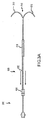
ここで図面を参照して、図1は、この発明の一実施例に従う腎臓への送達システム10を示す。システム10は、導入器アセンブリ100と、腎臓への送達カテーテル200と、たとえばバルーン血管形成術用カテーテル(図示せず)の導入に好適な冠動脈誘導カテーテル300とを含む。導入器アセンブリ100は、Y−ハブ110と、導入器シース120とを有し得る。典型的には、Y−ハブの遠位端112は、導入器シースの近位端124と結合される。送達カテーテル200は、遠位端202および近位端204を有する送達カテーテルシャフト201を含む。腎臓への送達カテーテルシャフト201は、送達カテーテルシャフトの遠位端202が導入器シースの遠位端122から延在し、かつ、送達カテーテルシャフトの近位端204がY−ハブの近位端114の第1のポート116から延在するように一部分が導入器アセンブリ100内に配置される。同様に、冠動脈誘導カテーテル300は、冠動脈誘導カテーテルの遠位端302が導入器シースの遠位端122から延在し、かつ、冠動脈誘導カテーテルの近位端304がY−ハブの近位端114の第2のポート118から延在するように一部分が導入器アセンブリ100内に配置される。導入器シース120の長さは、腎動脈のはるかに下で、好ましくは大動脈岐路50の下で終端するように選択され得る。この長さは典型的には、約5cmから約25cmの範囲にあり、典型的には約10cmから約15cmの範囲にある。多くの場合、導入器シース120は非常に薄い壁を有する。この壁は、できる限りまたはできるだけ薄くてもよく、血管の入口のプロファイルを最適にしかつ内径をより大きくすることができる。場合によっては、導入器シース120の外径は、たとえば1フレンチ未満または1フレンチに等しくてもよい。外径が約2フレンチであり得る場合もある。関連する事例において、導入器シ
ースの外径は、約0.005″から約.0025″の間の範囲内である場合もあれば、約0.009″から約0.015″の間の範囲内である場合もある。
Referring now to the drawings, FIG. 1 illustrates a
導入器アセンブリ100によって、単一の血管入口孔90を介して腎臓への送達カテーテル200および冠動脈誘導カテーテル300(および関連付けられる介入カテーテル)を患者の脈管構造に配置することが可能である。場合によっては、システム10は、冠動脈インターベンションなどの主要なカテーテル法の手順中に腎臓へ薬を注入するために使用できる。有利に、導入器シース120は、腎臓への注入手順のために注入カテーテル200を導入することと、冠動脈手順のために冠動脈誘導カテーテル300を導入することとを同時に容易にすることができる。典型的には、導入器シース120は、患者の大腿動脈30または腸骨動脈40の単一の孔90を通して、大動脈分岐部50の下または尾方に進められる。次いで、送達カテーテル200および冠動脈誘導カテーテル300は、導入器アセンブリ100を通して患者の身体に挿入され、それぞれの所望の場所に至る。図1は、配備された高プロファイルの構成の遠位分岐部210を有する送達カテーテル200を示す。以下にさらに記載するように、システム10は、低プロファイルの位置において送達カテーテル200の遠位分岐部210を制約するためのジャケットシース610を含み得る。
The
本発明者らは、上述の寸法を有する導入器シース120が多くの実用的な操作上の利点を内科医に提供できることを発見した。たとえば、内科医は、ジャケットシース610を引込んだり進めたりする間、導入器シース120を所定の位置に置いたままにすることができ、それによって、カニューレ挿入手順が単純になる。さらに、短い導入器シース120によって、患者の身体に送達カテーテル200を配置するためのフリーサイズのアプローチが可能になる。なぜなら、このシステムは、患者の解剖学的構造(たとえば、孔の箇所から腎動脈の起点または口までの距離)に従って各々の場合に最適にサイズ決めされた導入器シースを必要としないためである。このような特徴は、事例計画の際の標準化の改良に非常に適している。普遍的なサイズ決めは、患者の解剖学的構造に合わせるために予めサイズ決めされた導入器シースを使用する必要性をなくすことができる。
The inventors have discovered that an
関連して、この発明は、孔の箇所と配備箇所との間の距離が標準的な導入器シースの長さよりも大幅に小さい場合にそうであり得るように、入口箇所から近位に延在する余分な外部のシースの長さを有する必要性を回避する。導入器シース120を患者から引込むことが必要である場合、患者から近位に延在する長さを低減することによって、内科医が装置10の他の構成要素を操作する必要があり得る場所での干渉がより小さくなる。患者から近位に延在する導入器シース120の長さを低減することによって、冠動脈カテーテルなどの補助カテーテルが意図される箇所に到達するのに長さが不十分であるというリスクを回避または最小限に抑えることが可能である。言い換えると、導入器シース120を短くすることによって、Y−ハブ110を孔90などの血管の入口ポイントに接近させて配置できる。概して、冠動脈誘導カテーテルは、血管の入口箇所から冠状動脈までの典型的な距離にわたるようにサイズ決めされる。短くなった導入器シース120を使用することによって、誘導カテーテルが導入器アセンブリ100と結合されるが鼠蹊部の入口からあまりに遠く離れたままである状況を回避し、その結果、手順中に、誘導カテーテルの遠位端がターゲットの冠動脈血管に到達する前に誘導カテーテルの近位端がY−ハブ110と係合する。したがって、装置10の補助構成要素が直面する、患者の血管の内部の導入器シース120からの干渉または摩擦が少なくなる。有利に、この発明を使用することによって、腸骨、大動脈および他の血管のねじれに関連付けられる問題のうちの多くがなくなる。
Relatedly, the present invention extends proximally from the entry site so that it may be the case when the distance between the hole site and the deployment site is significantly less than the length of a standard introducer sheath. Avoid the need to have extra outer sheath length. If it is necessary to retract the
標準的な長さの導入器シースがしばしば大動脈に直接に配置され、カテーテル装置は絶えずそこを通される。有利に、この発明の短くなった導入器シースの寸法は、導入器シー
ス120およびY−ハブ110内で血餅が形成される可能性を最小限に抑える。したがって、このシステムは、導入器シース120での凝固を防止するように意図される一定の塩水またはヘパリン化された塩水の点滴の必要性をなくすまたは低減することができる。関連して、場合によっては、付属の市販製品を標準的な長さの導入器シースに通すとき、特に進めるときに、血餅が移動するリスクが増大する可能性がある。この発明の導入器シース120はこのようなリスクを最小限に抑える。この発明は、依然として全体が覆われた状態で遠位分岐部210を意図される配備箇所に前進させながら、このような利益を与える。したがって、この発明は、改良された安定特性をシステムに提供する。
A standard length introducer sheath is often placed directly into the aorta, and the catheter device is constantly passed therethrough. Advantageously, the shortened introducer sheath dimensions of the present invention minimize the possibility of clots forming within
導入器シース120の長さは、送達カテーテル200および冠動脈カテーテル300が両方とも腎動脈のはるかに下で導入器シース120を出ることができるようなものであり得る。したがって、冠動脈カテーテル300を進めるときに送達カテーテル200を移動させる機会が少なくなる。同様に、送達カテーテル200の遠位分岐部210が典型的には導入器シース120内に維持されないので、冠動脈誘導カテーテル300と送達カテーテル200との間に大幅な摩擦または他の妨害の問題が生じるとは考えにくい。これは、送達カテーテルの遠位端210が配備された構成にあろうと、配備されていない構成にあろうと、当てはまる。言い換えると、導入器シース120の長さによって、付属の冠動脈カテーテル300は腎動脈60から十分な距離を取ったところで導入器シース120を出ることができ、その結果、腎動脈60と相互作用するときに送達カテーテル200の改良された安定性を提供する。導入器シース120の長さが血管のねじれおよび他のシステム構成要素との起こり得る干渉に対処する必要性を低減するので、たとえばコイル補強材からのシース120用の実質的な柱状および径方向の支持体の必要性をなくすまたは大幅に低減することができる。導入器シース120は薄い壁の押出成形で準備することができ、壁の厚さは、現在使用されている複数層の補強シース管よりも小さい。
The length of the
さまざまな冠動脈手順を容易にすることに加えて、この発明は、幅広い種類の周辺手順と併用することもできる。一例では、この発明は、特に糖尿病の患者を治療する際に有用であり得る重体の患肢救済の場合について対側の浅大腿動脈(superficial femoral artery)(SFA)血管に進める際に使用できる。同様に、この発明は、腹部動脈または大腿動脈においてさまざまな手順を行なうために使用することができ、末梢血管の閉塞性疾患、重体の肢虚血および他の関連する状態を治療するために使用することができる。 In addition to facilitating various coronary procedures, the present invention can also be used with a wide variety of peripheral procedures. In one example, the invention can be used in advancing to the contralateral superficial femoral artery (SFA) vessel for the case of heavy limb salvage, which can be particularly useful in treating diabetic patients. Similarly, the present invention can be used to perform a variety of procedures in the abdominal or femoral arteries and used to treat peripheral vascular occlusive disease, heavy limb ischemia and other related conditions. can do.
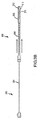
図2は、このような周辺手順に適したこの発明の一実施例に従う腎臓への送達システム10を示す。この目的に向けて、システム10は、導入器アセンブリ100と、送達カテーテル200と、周辺誘導カテーテル400とを含み得る。周辺誘導カテーテル400は、周辺誘導カテーテルの遠位端402が導入器シースの遠位端122から延在し、かつ、周辺誘導カテーテルの近位端404がY−ハブの近位端114の第2のポート118から延在するように一部分が導入器アセンブリ100内に配置される。腎臓への注入は、導入器アセンブリ100を通して、単一の血管の入口90を介して、対側の腸骨血管手順と同時に行なわれてもよい。導入器シースの遠位端122が大動脈分岐部50の下に位置し得るので、システム10は、対側のアクセスが所望である場合に、「引上げ開閉式の(up-and-over)」手順で使用できる。その結果、大動脈分岐部50の下に遠位端の位置を定めるために導入器シース120を引込む必要がなく、同様に、標準的な長さの導入器シースを使用する場合にそうでなければ血管の入口箇所から離れている可能性があるY−ハブ110において周辺カテーテル400のさらなる操作を行なう必要がない。導入器シース120は、周辺カテーテル400の作動長の最適な使用をもたらし、これは極度に遠位の手順に役立つことが多く、周辺カテーテル400に最適な取扱特性をもたらす。したがって、この発明は、大腿部ベースの冠動脈手順および周辺手順のために同様に普遍的に使用できるシステムを提供する。このシステム10は、周辺カテーテル400に対する摩擦を低減できる。なぜなら、送達カテーテル200および周辺カテーテル400の両方が通る導
入器シース120の長さが最小限に抑えられるためである。
FIG. 2 shows a
実施例によっては、送達カテーテル200は、治療または診断注入剤を腎動脈に送達するために使用できる。送達カテーテル200は、ステントの配置、治療エネルギの送達などを含む幅広い種類の他の治療および診断法を腎口57もしくは腎動脈60においてまたは腎口57もしくは腎動脈60の近くで行なうために使用できることも理解される。
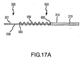
In some embodiments,
この発明は、制約された構成、またはそうでなければ配備されていないもしくは保護された構成に送達カテーテル200の遠位分岐部210を維持するための手段も提供する。図3Aおよび図3Bは、この発明の一実施例に従う制約アセンブリ600を示す。制約アセンブリ600は、リード630と結合されたジャケットシース610を含み、リード630は次にコネクタ620と結合され得る。図3Aは、制約のない構成または配備された構成の送達カテーテル200を示す。ジャケットシース610は、送達カテーテルの遠位分岐部210から引込まれる。送達カテーテル200は、配備後に取外すことができる犠牲的な長い薄壁の被覆ジャケット610を経て導入され得る。このような場合には、ジャケットシース610によって制約を受けることなく送達カテーテル200を引込むことができる。図3Bに示すように、遠位方向に送達カテーテルシャフト201に沿ってリード630を進めることによって、ジャケットシース610は、遠位分岐部210を包み、強制的に遠位分岐部210を折畳まれた、配備されていない、低プロファイルの構成にする。このように、遠位分岐部210を配備するまたは配備しないために、リード630を送達カテーテルシャフト201の長さに沿って引込むまたは進めることができる。場合によっては、遠位ジャケットシース610は、可動カバージャケットまたは捕捉シースとも称されてもよい。多くの場合、ジャケットシース610の直径は、送達カテーテル200の遠位延長部または先端部212を含むのに必要な大きさと同程度の大きさでしかない。
The present invention also provides a means for maintaining the
典型的には、送達カテーテルの遠位端210は、導入器アセンブリ100を介して患者の身体に挿入されるときには配備されていない構成にある。補足的に図1を参照して、たとえば、内科医は患者の大腿動脈30を通して、腸骨動脈40を通して、大動脈岐路50を通り越して、大動脈55を通して、腎口57におけるまたは腎口57の近くの所望の配備場所に、制約された送達カテーテルの遠位端210を進めてもよい。次いで、内科医は、遠位分岐部210を配備するために制約アセンブリ600を操作でき、それによって、腎臓へのカニューレ挿入手順が開始する。多くの場合、遠位分岐部210は遠位延長部212を含み、配備は遠位延長部212を腎動脈60と係合させることを含む。配備されていない送達カテーテルの遠位端210を患者の身体の中に進めることによって、遠位延長部212が血管外傷を引起すことを回避できる。多くの場合、配備された構成の送達カテーテルの遠位端210を進めることは困難であり得ると信じられている。折畳まれた、低プロファイルの状態によって、患者の脈管構造を通して遠位端の遠位延長部212を進めることが容易になる。
Typically, the
制約アセンブリ600は、さまざまな方法で設計および使用され得る。たとえば、図3Aに見られるように、リード630は送達カテーテルシャフト201を被覆する薄壁の外膜を含み得る。この実施例では、リード630は、同軸の態様でシャフト201上を移動可能な外側部材として、無傷のままであるように意図される。外側部材リード630を進めるまたは引込むことによって、カバージャケット610は遠位分岐部210の遠位延長部212を捕捉または解放する。この意味で、配備された構成とは、開いたまたは高プロファイルの構成を意味する。外側部材リード630を組込むことによって、送達カテーテルシャフト201に機能的外径が加えられることができ、場合によっては、リード630の外径がシャフト201の元の直径と等しいかまたはシャフト201の元の直径よりも小さい場合により小さなカテーテルシャフト201が必要になる可能性がある。関連して、外側部材630を組込むことによって、カテーテルシャフト201の機能的直径の大型化
が必要になる可能性がある。
The
この発明は、折畳まれた状態の遠位延長部212を可逆的に覆うまたは抑制するための幅広い種類の手段を企図する。以下にさらに記載するように、制約アセンブリは、ジャケット、シース、スリーブ、カバー、制御ワイヤまたはロッドなどのさまざまな組合せを含むことができる。この発明は、確実に患者の身体に装置10を所望に配置するために誘導ワイヤなどの誘導アセンブリを含み得るか、またはそうでなければ誘導アセンブリと動作可能に関連付けられ得ることがさらに理解される。誘導ワイヤの誘導によって、配備、カニューレ挿入および取外し中に送達カテーテル200および/または誘導カテーテル300,400を誘導して進めることが可能である。場合によっては、誘導ワイヤの誘導は、装置の取外しには必要でないかもしれない。たとえば、装置の取外しは単に、遠位延長部212をジャケット610に引込むことと、折畳まれた分岐部の端部210を脈管構造を通して導入器シース120および入口箇所から傷つけないように引抜くこととを含み得る。
The present invention contemplates a wide variety of means for reversibly covering or restraining the
装置10は、折畳まれた構成または折畳まれていない構成のいずれかで引込まれ得る。場合によっては、遠位延長部212は、図4に示すように、損傷を引起すことなく折畳まれていない構成で患者の腎口57から引込むのに十分に軟らかくかつ曲げやすい。たとえば、経皮的な適用例によっては、遠位延長部212がまだ折畳まれていない構成にある間に送達カテーテル200を取外すことが十分であることが多い。他の場合には、内科医は、血管外傷の可能性および血小板、血栓などの変位を低減するために、折畳まれた傷つけない構成で装置10を取外す。
The
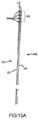
図5Aおよび図5Bは、単一レールの誘導システムを使用するこの発明の特定の実施例を示す。図5Aに示す送達カテーテル200は、制約アセンブリ600のジャケットシース610が遠位分岐部210を低プロファイルの構成で維持しているので、配備されていない状態である。ジャケットシース610は、誘導ワイヤ700を摺動可能に受けるように適合されたガイド612を含む。ここで、ガイド612は、誘導ワイヤ700がシース610の内部管腔の横に配置されるように、シース610の本体と貼付けられた長手方向の管を含む。他の実施例では、ガイド612は誘導ワイヤ700を摺動可能に係合させるための他の手段を含んでいてもよいことが理解される。送達カテーテル200が患者の動脈を通して進められると、ガイド612は、誘導ワイヤ700に沿って摺動するが、同時に送達カテーテルの遠位分岐部210に対しては固定されたままである。一実施例では、リード630は、軸方向に配置された円筒形の外側部材の代わりに制御ワイヤまたはロッドを含み、したがって、送達カテーテルシャフト201上で十分な同軸の構成を持たない。カバージャケット610は、送達カテーテルシャフト201に同軸に位置することができ、送達カテーテルシャフト201の上に永久にとどまる。図5Bに示す送達カテーテル200は、ジャケットシース610が遠位分岐部210から離れて引込まれているので、配備された構成にある。典型的には、この引込みは近位方向に誘導ワイヤ700に沿ってガイド612を摺動させることも含むが、実施例によっては、制約アセンブリ600の引込みは誘導ワイヤ700の引込みを伴うことになる。場合によっては、ガイド612は一連の分割された管状のセグメントを含み得る。関連する事例において、ガイド612はC字型の断面を有する部分的に管状のセグメントを含んでいてもよく、それによって、ガイド612を誘導ワイヤ700に嵌めたり誘導ワイヤ700から外したりすることができる。
5A and 5B illustrate a specific embodiment of the present invention that uses a single rail guidance system. The
上述のように、ジャケットシース610は前進および引込みのためにリード630と結合され得る。リード630はさまざまな制御ワイヤまたは小さな直径のシャフトもしくはロッドのいずれかを含み得ることが理解される。いくつかの繰返しにおいて、リード630はジャケットシース610と永久に取付けられ、他の繰返しにおいては、リード630
はジャケットシース610と取外し可能に結合される。場合によっては、ジャケットシース610は、取付けられたリード630がない状態で導入器アセンブリのY−ハブ110のすぐ外側に位置決めされ得る。この構成は、ジャケットシース610からリード630を取外すまたは切離す機能を選択することによって容易になる。一方で、リード630をカバージャケットシース610と永久に接続させることを選択することによって、製造の際の単純さならびに潜在的に高い強度および使いやすさが提供され得る。実施例によっては、リード630の長さは約35cmであり、カテーテル法の手順と干渉しないようにその直径は十分に狭い。着脱可能なリード630のための別の構成は、誘導ワイヤなどの現在利用可能なワイヤにカバージャケットを接続する手段を使用し、これは、ジャケットに接続する特定の手段を有する専用の制御ワイヤに向いている。
As described above, the
Is removably coupled to the
図6Aに示すように、ジャケットシース610の近位端611は、誘導ワイヤ(図示せず)を受けるためのアパーチャ612aを含んでいてもよく、その結果、誘導ワイヤのセグメントがシース610内に収容される。ここで、ガイド612は実質的にジャケットシース610の円筒形の壁の内部にある。図6Bおよび図6Cに示す実施例では、ジャケットシース610は、遠位延長部212を収容するための2つの管腔616と、誘導ワイヤ700を収容するための管腔618とを含む。
As shown in FIG. 6A, the
図7Aおよび図7Bは、割れた管のタイプのジャケットシース610を含む制約アセンブリ600の別の実施例を示す。誘導ワイヤ700を、単一レールタイプのガイドに通す代わりに、割れ目619に通してもよい。同様に、送達カテーテルシャフト201または誘導カテーテル300、400を割れ目619に通してもよく、したがって、ジャケットシース610の容易な取外しおよび交換が可能になる。図7Cに示すように、場合によっては、ジャケットシース610は、連続していなくてもよいが、その代わりに複数のセグメントを含み得る。このような構成は、脈管構造に導入するために与えられる材料が少なくなり、したがって、凝固のリスクを減らすことによって有利である可能性がある。関連して、与えられる管腔の表面が小さくなることによって、ジャケットシース610と送達カテーテル200または付属のカテーテル300、400との間の摩擦の量が。
FIGS. 7A and 7B illustrate another embodiment of a
図8に見られるように、ジャケットシース610は、Y−ハブ110の第1のポート116に通されることができる。リード630は、ジャケットシース610の移動を制御するように内科医によって操作され得る。導入器シース120およびY−ハブ110から患者の血管の入口90の外側にジャケット610を十分に引込むことができるようにすることによって、患者の中に残っている装置10(たとえば、カテーテル200、300または400)の機能的直径を低減できる。多くの場合、ジャケットシースは休止時間中は患者の身体の外側でとどまることができる。関連して、直径がより大きい送達カテーテル200、付属の冠動脈カテーテル300、または周辺カテーテル400を、このような十分に引込み可能なジャケット610を有する装置10において使用してもよい。同じ理由で、外径がより小さい導入器シース120を使用してもよい。ジャケットシース610は位置確認のためのマーカ617を含んでいてもよい。実施例によっては、マーカ617は放射線不透過性材料を含んでいてもよい。
As seen in FIG. 8, the
図9Aおよび図9Bは、送達カテーテル200のための、形状が変化し得る遠位アームの構成を示す。カテーテル200は、曲線の内側になる各遠位延長部212の側に、遠位延長部212の内側遠位先端部と貼付けることができる分岐した引張りワイヤ205を含んでいてもよい。したがって、引張りワイヤ205に張力がかかると、引張りワイヤ205は、引張りワイヤ205が取付けられている遠位延長部212の側を事実上短くし、湾曲させる。遠位延長部212が湾曲し、互いから分離したこの配備された向きを図9Aに示す。引張りワイヤ205を解放することによって、遠位延長部212はデフォルトの静止した直線の構成に戻ることができる。この折畳まれた向きを図9Bに示す。
9A and 9B show a distal arm configuration for the
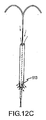
図10Aおよび図10Bは、送達カテーテル200が、送達カテーテル200を配備するより前に血管の機能的断面を最大にするための、先細りになった、傷つけない遠位先端部もしくは円錐750、または他の拡張器手段を含むこの発明の別の実施例を示す。場合によっては、遠位先端部750は送達カテーテル200とは結合されない。場合によっては、遠位先端部750は、誘導ワイヤ700と併用できるレールまたは管腔などのガイド752を有していてもよい。誘導ワイヤ700は、遠位カテーテルのアームのカニューレ挿入のために進められるときに先細りになった円錐750が血管穿孔を作り出す可能性を低減できる柔軟なタイプのワイヤであり得る。誘導ワイヤの直径はさまざまであってもよいが、多くの場合、約0.035インチである。図10Aは、高プロファイルの配備された構成の送達カテーテル200の遠位延長部212を示す。ジャケットシース610は、カテーテルシャフト201に装着されるかまたはそうでなければカテーテルシャフト201と接続されるシールまたはガスケット611を含んでいてもよく、したがって、封止された状態でジャケットシース610の内面と係合したまま送達カテーテルシャフト201が進んだり引込まれたりする状態で進んだり引込まれたりする。ここで、ガスケット611はジャケットシース610の遠位端に向かって配置され、ジャケットシースの近位端は別の方法で封止される。したがって、遠位分岐部210が配備された状態にあるときにジャケットシース610を血流に対して閉じることができる。図10Bは、低プロファイルの配備されていない構成の送達カテーテル200の遠位延長部212を示す。ここで、ガスケット611はジャケットシース610の近位端に向かって配置され、遠位円錐750は事実上ジャケットシース610の遠位端を封止する。血液がジャケットシース610を通って流れるのを防止することによって、ガスケット610はシース610内で血栓が形成されるリスクを低減するのを助けることができる。
FIGS. 10A and 10B illustrate a tapered, non-injuring distal tip or
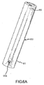
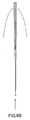
遠位遠位延長部212を制約するためのカバージャケットシース610は、全体的な製品のニーズによって、複数の構成を有し得る。たとえば、ジャケットシース610は、誘導ワイヤの管腔または単一レールタイプの構成に対応可能である。さらに、ジャケットシース610は各端部上に先細りの形状を有して設計される場合もあれば、図11に示すように、先細りになっていない近位端および先細りになった遠位端を含む場合もある。ここで、ガイド612の遠位端はジャケットシース610の中央先端部において出るのに対して、遠位分岐部210は中央先端部に対して横方向に出る。このような構成によって、外傷がより少ない状態で送達カテーテル200を患者の脈管構造に通すことができる。
The
この発明は、たとえば停滞したまたは静止した血液が中に溜まるのを回避することによって、ジャケットシース610内に血餅または血栓が形成されることを防止または抑制するためのさまざまなアプローチを提供する。場合によっては、これらのアプローチは、送達カテーテルシャフト201と依然として一体的であるジャケットシース610を含む。図12Aに示すように、ジャケットシース610は、血液がシース610に流入するまたはシース610を通って流れるのを防止するために封止された状態で送達カテーテルシャフト201と協働し得る。ガスケット611は、ジャケットシース610の遠位端における血液の注入または注入剤の浸出を防止することができ、シース610の近位端は別の方法でシャフト201で封止されてもよい。ガスケット611は、シャフト201と固定されることができ、封止された状態でジャケットシース610の内面と係合することができる。図12Bは、ジャケットシース610の内部と流体連通するポート206を有する送達カテーテルシャフト200を示す。ポート206は、送達カテーテルシャフト201からシース610に注入剤を送達するために使用できる。注入剤がジャケットシース610の管腔空間または事実上の空洞を充填できるようにすることによって、この空洞への注入剤の正の流入を作り出すことができ、その結果、血栓の形成を防止または抑制する。同様に、ポート206からの注入剤でジャケットシース610の内部室を加圧できる。多くの場合、ジャケットシース610は、血液の注入または注入剤の浸出を防止するために1つ
以上のガスケットまたはシール611で封止されることになる。注入剤の事実上の貯留場所の正圧は、ジャケットシース610に残っている空洞に蓄積し得る。(血圧よりも大きな)わずかな圧力が存在するので、血液は空洞の中の注入剤をそれほど容易に移動させることができず、したがって、凝固を防止する。図12Cに見られるような封止されていないまたは開放したバージョンでは、ジャケットシース610は、ジャケットシース610を通る連続的な血流を可能にするために近位端出口または穿孔613を含み得る。ここで、入ってくる血液は、ジャケットシース610における開窓、スロットまたは他の開口613を介してシース610から潅流する。
The present invention provides various approaches to prevent or inhibit the formation of clots or thrombi within the
図13は、この発明の一実施例に従う送達カテーテルシャフト201の部分図を示す。リード630は、半円形または変形された「D」の形状で成形され、送達カテーテルシャフト201と入れ子になっており、したがって、容易に導入器シース(図示せず)を通ることになる。リード630は、さまざまな形状のうちのいずれかを有することができ、リード630および送達カテーテルシャフト201の組合せの幾何学的形状または機能的直径(もしくは機能的断面積)全体を最小限に抑えるように往々にして構成されることになることが理解される。関連する実施例では、リード630は、レールタイプのシステムとして送達カテーテルシャフト201の長さに沿って移動する、ポリマーまたは金属で作られた、半分が畝状になった管であり得る。この意味で、リード630にトルクをかける必要性は限られるがリード630が依然としてジャケットシース610の前進および引込みに関連付けられる圧縮力ならびに張力に耐える必要がある場合に、変形された「D」の形状は有用である可能性がある。
FIG. 13 shows a partial view of a
図14Aおよび図14Bは、この発明の一実施例に従う制約アセンブリ600および送達カテーテル200を示す。図14Aは、送達カテーテル200の遠位延長部212が配備された向きになるような、引込まれた位置にある制約アセンブリ600を示す。図14Bは、送達カテーテル200の遠位延長部212が配備されていない向きになるような、進んだ位置にある制約アセンブリ600を示す。送達カテーテル200のクランプ207とコネクタ620をロックするかまたはそうでなければ取外し可能に結合することによって、制約アセンブリ600を進んだ位置に固定できる。場合によっては、制約アセンブリ600のすべての構成要素(たとえば、ハンドル620、リード630およびシースジャケット610)は、Y−ハブ110(ここでは図示せず)を通して、および誘導ワイヤ700(ここでは図示せず)に沿って、容易に進めることができるように構築され得る。
14A and 14B show a
図15Aおよび図15Bは、この発明の一実施例に従う制約アセンブリ600および送達カテーテル200を示す。制約アセンブリ600は、送達カテーテル200を同軸の態様で摺動して係合させるように構成された複数のリング640aを含む折畳み可能なリング捕捉システム640を含む。コネクタ630は、折畳み可能なリング捕捉システム640の1つ以上のリング640aと結合され得る。図15Aは、送達カテーテル200の遠位延長部212が配備されていない構成になるような、進んだ位置にある制約アセンブリ600を示す。図15Bは、送達カテーテル200の遠位延長部212が配備された構成になるような、引込まれた位置にある制約アセンブリ600を示す。コネクタ630が引込まれると、リング640aはカテーテルのハイポチューブまたはシャフト201の上に摺動し、したがって、遠位延長部212が開いた構成になることが可能である。リング640aは、一旦ハイポチューブまたはシャフト201の上に引込まれると、ハイポチューブ201の表面上に折畳めて、血管の機能的断面積を最適化するように設計されることができる。
15A and 15B show a constraining
図16Aおよび図16Bは、この発明の一実施例に従う、制約された状態で送達カテーテル200を腎口または他の配備場所に進めるための手段を示す。図16Aは、抑制された位置にある遠位分岐部210を示す。遠位分岐部210の各遠位延長部212は、遠位
延長部212と結合された誘導ワイヤリング212aを含み、その結果、誘導ワイヤリング212aは誘導ワイヤ700と摺動可能に協働する。誘導ワイヤリング212aは、遠位延長部212の遠位先端部にもしくは遠位延長部212の遠位先端部の近くに、または遠位延長部212の長さに沿った任意の場所に配置され得る。遠位延長部212が多かれ少なかれ位置合わせされるかまたは互いに平行であるように遠位分岐部210が軸方向に制約された状態で配置されると、誘導ワイヤ700がリング212aを通して配置されるようにリング212aを位置合わせでき、したがって、遠位延長部212をまとめる。実施例によっては、誘導ワイヤ700は、0.035″の直径の誘導ワイヤであってもよい。図16Bに見られるように、送達カテーテル200が腎動脈などの配備場所においてまたは配備場所のあたりで所定の位置に配置されると、誘導ワイヤ700を引抜くことができ、遠位延長部212は配備された向きに向けて動くことが可能である。腎動脈のカニューレ挿入は、前に援用された米国特許出願第11/084,738号に記載される態様で達成できる。
FIGS. 16A and 16B illustrate means for advancing the
図17Aおよび図17Bは、この発明の一実施例に従う、制約された状態で送達カテーテル200を腎臓周辺の大動脈または他の配備場所に進めるための手段を示す。図17Aは、抑制された向きにある遠位分岐部210を示す。制約アセンブリ600はばね650を含み、ばねの遠位端652はジャケットシース610と結合され、ばねの近位端654は送達カテーテルシャフト201と結合される。ここで、ばね650は緩んだ状態にあり、ジャケットシース610は、遠位延長部212を折畳まれた構成に制約するために送達カテーテルシャフト201に沿って遠位に配置されたままである。挿入および配備の後、ばねによって荷重をかけられるジャケット610は、リード630における張力を解放してばね650を緩めることによって、引抜きのために遠位延長部212を容易に再び捕らえることができる。図17Bは、配備された構成の遠位分岐部210を示す。送達カテーテル200が所望の配備場所、たとえば大動脈に配置されると、ジャケットシース610を引込み、ばね650を圧縮するように、リード630を作動させることができ、それによって、遠位延長部212はたとえば大動脈壁に対して開くことができる。
17A and 17B show a means for advancing the
上述のように、ワイヤタイプのリード630(図5Aに図示)と組合せられた送達カテーテルシャフトまたはハイポチューブ201を含む実施例はしばしば、同軸スリーブ管タイプのリード630(図3Aに図示)と組合せられた送達カテーテルシャフトまたはハイポチューブ201を含む実施例よりも小さなプロファイルまたは機能的断面直径を提供できる。場合によっては、遠位分岐部210を制約された向きに戻すために、配備された遠位延長部212の上にジャケットシース610を進めるのに実質的な押す動きまたは圧縮力が必要である場合に、同軸コネクタスリーブ管タイプのリード630が有用であり得ることが理解される。しかしながら、本発明者らは、上述のばねによって荷重をかけられるジャケットシース610を使用することによって、圧縮力をシース610にかけるためにリード630を押す必要性がなくなるまたは低減され得ることを発見した。関連して、ばね650または同様のばねのような手段は、一定の圧縮荷重をカテーテルシャフト201に与えることができ、一定の引張荷重をリード630に与えることができる。これらの力の大きさは、所望のごとく互いに適切に相対的に決めることができる。場合によっては、送達カテーテルのハイポチューブまたはシャフト201の外径(outer diameter)(OD)は約1フレンチから約3フレンチの間の範囲にあり得る。場合によっては、リード630の直径は、約0.010から約0.025″の間の範囲にあり得る。リード630は、送達カテーテルハイポチューブ201に適切にサイズ決めされることができる。
As described above, embodiments including a delivery catheter shaft or
この発明は、誘導カテーテルを含まない独立型の送達カテーテルシステムとともに使用することにも適している。図18に見られるように、装置10は、導入器シース120を含むがY−ハブ110を含まない導入器アセンブリ100を通すように構成された送達カテーテル200を含む。この構成は、第2の付属のカテーテル300、400が必要では
なく、したがって、このような独立型のシステムとともに全体的により低いプロファイルを達成できる状況で有用であり得る。
The present invention is also suitable for use with a stand-alone delivery catheter system that does not include a guide catheter. As seen in FIG. 18, the
上記はこの発明の特定の実施例を十分かつ完全に開示するが、さまざまな修正例、代替的な構築物および等化物を所望のごとく利用してもよい。したがって、上の説明および例はこの発明を限定するように解釈されるべきではなく、この発明は添付の特許請求の範囲によって規定される。 While the above discloses a specific embodiment of the present invention fully and completely, various modifications, alternative constructions and equivalents may be utilized as desired. Accordingly, the above description and examples should not be construed as limiting the invention, which is defined by the appended claims.
Claims (20)
腸骨動脈に導入器シースを位置決めすることと、
遠位分岐部を有する腎臓への送達カテーテルを前記導入器シースを通して進めることと、
前記遠位分岐部を低プロファイルの構成に制約することと、
制約された遠位分岐部が制約された状態のまま前記分岐部を前記導入器シースから前記腎動脈の方に進めることと、
前記遠位分岐部の第1の遠位延長部が前記腎動脈の一方に入ることができ、かつ、前記遠位分岐部の第2の遠位延長部が他方の腎動脈に入ることができるように、制約された低プロファイルの構成から前記遠位分岐部を解放することとを備える、方法。 A method for positioning a delivery catheter in a renal artery, comprising:
Positioning an introducer sheath in the iliac artery;
Advancing a delivery catheter to the kidney having a distal bifurcation through the introducer sheath;
Constraining the distal bifurcation to a low profile configuration;
Advancing the bifurcation from the introducer sheath toward the renal artery while the constrained distal bifurcation is constrained;
A first distal extension of the distal bifurcation can enter one of the renal arteries, and a second distal extension of the distal bifurcation can enter the other renal artery. Releasing the distal bifurcation from a constrained low profile configuration.
遠位分岐部を有する送達カテーテルと、
Y−ハブに動作可能に関連付けられた導入器シースを備える導入器アセンブリとを備え、前記導入器シースの長さは、約5cmから約25cmの範囲にあり、Y−ハブは、前記送達カテーテルを受けるための第1のポートと、第2のカテーテルを受けるための第2のポートとを含み、前記システムはさらに、
前記導入器シースを越えて遠位に進められたときに前記送達カテーテルの前記遠位分岐部を低プロファイルの構成で保持するための制約アセンブリを備える、システム。 A system for delivering therapy to a renal artery,
A delivery catheter having a distal bifurcation;
An introducer assembly comprising an introducer sheath operatively associated with a Y-hub, wherein the length of the introducer sheath is in the range of about 5 cm to about 25 cm, and the Y-hub includes the delivery catheter. A first port for receiving and a second port for receiving a second catheter, the system further comprising:
A system comprising a constraint assembly for retaining the distal bifurcation of the delivery catheter in a low profile configuration when advanced distally over the introducer sheath.
前記主要な管腔に導入器シースを位置決めすることと、
遠位分岐部を有する送達カテーテルを前記導入器シースを通して進めることと、
前記遠位分岐部を低プロファイルの構成に制約することと、
制約された遠位分岐部を前記導入器シースから前記管腔枝の方に進めることと、
前記遠位分岐部の第1の遠位延長部が前記管腔枝に入ることができるように、前記遠位分岐部を制約された低プロファイルの構成から解放することとを備える、方法。 A method of positioning a delivery catheter in a lumen branch extending from a main lumen in a patient's body comprising:
Positioning an introducer sheath in the main lumen;
Advancing a delivery catheter having a distal bifurcation through the introducer sheath;
Constraining the distal bifurcation to a low profile configuration;
Advancing a constrained distal bifurcation from the introducer sheath toward the lumen branch;
Releasing the distal bifurcation from a constrained low profile configuration so that a first distal extension of the distal bifurcation can enter the luminal branch.
Applications Claiming Priority (2)
| Application Number | Priority Date | Filing Date | Title |
|---|---|---|---|
| US11/241,749 US7993325B2 (en) | 2002-09-20 | 2005-09-29 | Renal infusion systems and methods |
| PCT/US2006/037025 WO2007041031A2 (en) | 2005-09-29 | 2006-09-21 | Renal infusion systems and methods |
Publications (2)
| Publication Number | Publication Date |
|---|---|
| JP2009509644A true JP2009509644A (en) | 2009-03-12 |
| JP2009509644A5 JP2009509644A5 (en) | 2009-12-10 |
Family
ID=37906662
Family Applications (1)
| Application Number | Title | Priority Date | Filing Date |
|---|---|---|---|
| JP2008533463A Pending JP2009509644A (en) | 2005-09-29 | 2006-09-21 | Kidney injection system and method |
Country Status (4)
| Country | Link |
|---|---|
| US (1) | US7993325B2 (en) |
| EP (1) | EP1928535A2 (en) |
| JP (1) | JP2009509644A (en) |
| WO (1) | WO2007041031A2 (en) |
Cited By (1)
| Publication number | Priority date | Publication date | Assignee | Title |
|---|---|---|---|---|
| US8518011B2 (en) | 2004-03-04 | 2013-08-27 | Angiodynamics, Inc. | Sheath for use in peripheral interventions |
Families Citing this family (64)
| Publication number | Priority date | Publication date | Assignee | Title |
|---|---|---|---|---|
| US6749598B1 (en) * | 1999-01-11 | 2004-06-15 | Flowmedica, Inc. | Apparatus and methods for treating congestive heart disease |
| US6355425B1 (en) * | 1999-03-26 | 2002-03-12 | Billups-Rothenberg, Inc. | Mutations associated with iron disorders |
| US7756583B2 (en) | 2002-04-08 | 2010-07-13 | Ardian, Inc. | Methods and apparatus for intravascularly-induced neuromodulation |
| US8150519B2 (en) | 2002-04-08 | 2012-04-03 | Ardian, Inc. | Methods and apparatus for bilateral renal neuromodulation |
| US8774922B2 (en) | 2002-04-08 | 2014-07-08 | Medtronic Ardian Luxembourg S.A.R.L. | Catheter apparatuses having expandable balloons for renal neuromodulation and associated systems and methods |
| US9308044B2 (en) | 2002-04-08 | 2016-04-12 | Medtronic Ardian Luxembourg S.A.R.L. | Methods for therapeutic renal neuromodulation |
| US7653438B2 (en) | 2002-04-08 | 2010-01-26 | Ardian, Inc. | Methods and apparatus for renal neuromodulation |
| US7853333B2 (en) | 2002-04-08 | 2010-12-14 | Ardian, Inc. | Methods and apparatus for multi-vessel renal neuromodulation |
| US8131371B2 (en) | 2002-04-08 | 2012-03-06 | Ardian, Inc. | Methods and apparatus for monopolar renal neuromodulation |
| US9636174B2 (en) | 2002-04-08 | 2017-05-02 | Medtronic Ardian Luxembourg S.A.R.L. | Methods for therapeutic renal neuromodulation |
| US20070129761A1 (en) | 2002-04-08 | 2007-06-07 | Ardian, Inc. | Methods for treating heart arrhythmia |
| US8145317B2 (en) * | 2002-04-08 | 2012-03-27 | Ardian, Inc. | Methods for renal neuromodulation |
| US20140018880A1 (en) | 2002-04-08 | 2014-01-16 | Medtronic Ardian Luxembourg S.A.R.L. | Methods for monopolar renal neuromodulation |
| US8145316B2 (en) | 2002-04-08 | 2012-03-27 | Ardian, Inc. | Methods and apparatus for renal neuromodulation |
| US9308043B2 (en) | 2002-04-08 | 2016-04-12 | Medtronic Ardian Luxembourg S.A.R.L. | Methods for monopolar renal neuromodulation |
| US8347891B2 (en) | 2002-04-08 | 2013-01-08 | Medtronic Ardian Luxembourg S.A.R.L. | Methods and apparatus for performing a non-continuous circumferential treatment of a body lumen |
| US8774913B2 (en) | 2002-04-08 | 2014-07-08 | Medtronic Ardian Luxembourg S.A.R.L. | Methods and apparatus for intravasculary-induced neuromodulation |
| US20080213331A1 (en) | 2002-04-08 | 2008-09-04 | Ardian, Inc. | Methods and devices for renal nerve blocking |
| US7617005B2 (en) | 2002-04-08 | 2009-11-10 | Ardian, Inc. | Methods and apparatus for thermally-induced renal neuromodulation |
| US7162303B2 (en) | 2002-04-08 | 2007-01-09 | Ardian, Inc. | Renal nerve stimulation method and apparatus for treatment of patients |
| US20070135875A1 (en) | 2002-04-08 | 2007-06-14 | Ardian, Inc. | Methods and apparatus for thermally-induced renal neuromodulation |
| US7620451B2 (en) | 2005-12-29 | 2009-11-17 | Ardian, Inc. | Methods and apparatus for pulsed electric field neuromodulation via an intra-to-extravascular approach |
| US6978174B2 (en) | 2002-04-08 | 2005-12-20 | Ardian, Inc. | Methods and devices for renal nerve blocking |
| US8150520B2 (en) | 2002-04-08 | 2012-04-03 | Ardian, Inc. | Methods for catheter-based renal denervation |
| US7585836B2 (en) * | 2004-05-14 | 2009-09-08 | Goodson Iv Harry Burt | Bi-lateral local renal delivery for treating congestive heart failure and for BNP therapy |
| EP1585572A4 (en) | 2002-09-20 | 2010-02-24 | Flowmedica Inc | Method and apparatus for intra aortic substance delivery to a branch vessel |
| US7993325B2 (en) | 2002-09-20 | 2011-08-09 | Angio Dynamics, Inc. | Renal infusion systems and methods |
| WO2004032791A2 (en) * | 2002-09-20 | 2004-04-22 | Flowmedica, Inc. | Method and apparatus for selective material delivery via an intra-renal catheter |
| JP2006526464A (en) * | 2003-06-05 | 2006-11-24 | フローメディカ,インコーポレイテッド | System and method for performing bilateral intervention or diagnosis in a branched body lumen |
| EP1659970A4 (en) * | 2003-08-05 | 2008-05-21 | Flowmedica Inc | Sytem and method for prevention of radiocontrast induced nephropathy |
| US7937143B2 (en) | 2004-11-02 | 2011-05-03 | Ardian, Inc. | Methods and apparatus for inducing controlled renal neuromodulation |
| US20070167913A1 (en) * | 2005-10-11 | 2007-07-19 | Flowmedica, Inc. | Vascular sheath with variable lumen construction |
| US20080249484A1 (en) * | 2005-10-28 | 2008-10-09 | Invatec S.R.L. | Auxiliary Probes |
| US7771401B2 (en) * | 2006-06-08 | 2010-08-10 | Angiodynamics, Inc. | Selective renal cannulation and infusion systems and methods |
| US7771465B2 (en) * | 2006-06-23 | 2010-08-10 | Gore Enterprise Holdings, Inc. | Branched stent delivery system |
| US7998162B2 (en) | 2007-03-05 | 2011-08-16 | Pei Ho | System and method for embolic protection |
| US20080221551A1 (en) * | 2007-03-09 | 2008-09-11 | Flowmedica, Inc. | Acute kidney injury treatment systems and methods |
| US9149610B2 (en) | 2007-05-31 | 2015-10-06 | Abbott Cardiovascular Systems Inc. | Method and apparatus for improving delivery of an agent to a kidney |
| US8216209B2 (en) * | 2007-05-31 | 2012-07-10 | Abbott Cardiovascular Systems Inc. | Method and apparatus for delivering an agent to a kidney |
| US9364586B2 (en) | 2007-05-31 | 2016-06-14 | Abbott Cardiovascular Systems Inc. | Method and apparatus for improving delivery of an agent to a kidney |
| US9144509B2 (en) | 2007-05-31 | 2015-09-29 | Abbott Cardiovascular Systems Inc. | Method and apparatus for delivering an agent to a kidney |
| US20090105799A1 (en) * | 2007-10-23 | 2009-04-23 | Flowmedica, Inc. | Renal assessment systems and methods |
| US20110190778A1 (en) * | 2008-07-28 | 2011-08-04 | Paul Arpasi | Multiple Port Introducer for Thrombolysis |
| US8652129B2 (en) | 2008-12-31 | 2014-02-18 | Medtronic Ardian Luxembourg S.A.R.L. | Apparatus, systems, and methods for achieving intravascular, thermally-induced renal neuromodulation |
| US8292941B2 (en) * | 2009-04-23 | 2012-10-23 | Medtronic Vascular, Inc. | Delivery system for deployment of a one-piece iliac-branch device |
| US20110301684A1 (en) * | 2010-06-08 | 2011-12-08 | Svelte Medical Systems, Inc. | System and method for performing angiography and stenting |
| US9066720B2 (en) | 2010-10-25 | 2015-06-30 | Medtronic Ardian Luxembourg S.A.R.L. | Devices, systems and methods for evaluation and feedback of neuromodulation treatment |
| WO2013090619A1 (en) | 2011-12-15 | 2013-06-20 | The Board Of Trustees Of The Leland Stanford Junior University | Devices and methods for preventing tracheal aspiration |
| US9750568B2 (en) | 2012-03-08 | 2017-09-05 | Medtronic Ardian Luxembourg S.A.R.L. | Ovarian neuromodulation and associated systems and methods |
| EP3348220A1 (en) | 2012-03-08 | 2018-07-18 | Medtronic Ardian Luxembourg S.à.r.l. | Biomarker sampling in the context of neuromodulation devices and associated systems |
| EP2885017B1 (en) * | 2012-08-17 | 2019-04-24 | Boston Scientific Scimed, Inc. | Guide extension catheter |
| US20140110296A1 (en) | 2012-10-19 | 2014-04-24 | Medtronic Ardian Luxembourg S.A.R.L. | Packaging for Catheter Treatment Devices and Associated Devices, Systems, and Methods |
| US9770194B2 (en) | 2013-11-05 | 2017-09-26 | Ciel Medical, Inc. | Devices and methods for airway measurement |
| US9980766B1 (en) | 2014-03-28 | 2018-05-29 | Medtronic Ardian Luxembourg S.A.R.L. | Methods and systems for renal neuromodulation |
| US10194980B1 (en) | 2014-03-28 | 2019-02-05 | Medtronic Ardian Luxembourg S.A.R.L. | Methods for catheter-based renal neuromodulation |
| US10194979B1 (en) | 2014-03-28 | 2019-02-05 | Medtronic Ardian Luxembourg S.A.R.L. | Methods for catheter-based renal neuromodulation |
| CN107735138A (en) | 2015-04-15 | 2018-02-23 | 桑福德保健公司 | Pulmonary embolism device |
| GB2556021B (en) * | 2016-07-11 | 2022-11-23 | Ganapathy Ramesh | Medical apparatus |
| US10537709B2 (en) | 2016-10-18 | 2020-01-21 | Boston Scientific Scimed, Inc. | Guide extension catheter |
| US20200353223A1 (en) * | 2017-11-07 | 2020-11-12 | The Johns Hopkins University | Flagella balloon catheter and wire |
| WO2019136357A1 (en) * | 2018-01-08 | 2019-07-11 | St. Jude Medical, Cardiology Division, Inc. | Introducer positioning device for controlling a catheter shaft |
| US20220218393A1 (en) * | 2019-05-14 | 2022-07-14 | Tufts Medical Center, Inc. | Systems and methods for accessing a renal capsule for diagnostic and therapeutic purposes |
| US11547786B2 (en) | 2020-04-03 | 2023-01-10 | Tufts Medical Center, Inc. | Expandable ECMO extension cannula system |
| US11738131B2 (en) | 2020-04-03 | 2023-08-29 | Tufts Medical Center, Inc. | Expandable ECMO extension cannula system |
Citations (6)
| Publication number | Priority date | Publication date | Assignee | Title |
|---|---|---|---|---|
| JPH06197972A (en) * | 1992-03-30 | 1994-07-19 | Pameda Nv | Rapidly exchangeable catheter system |
| US5720735A (en) * | 1997-02-12 | 1998-02-24 | Dorros; Gerald | Bifurcated endovascular catheter |
| US6086557A (en) * | 1998-10-01 | 2000-07-11 | Cardiothoracic Systems, Inc. | Bifurcated venous cannula |
| US6261316B1 (en) * | 1999-03-11 | 2001-07-17 | Endologix, Inc. | Single puncture bifurcation graft deployment system |
| JP2003102843A (en) * | 2001-09-28 | 2003-04-08 | Nippon Zeon Co Ltd | Medical sheath |
| WO2004034767A2 (en) * | 2002-09-20 | 2004-04-29 | Flowmedica, Inc. | Catheter system for renal therapy |
Family Cites Families (214)
| Publication number | Priority date | Publication date | Assignee | Title |
|---|---|---|---|---|
| US1696018A (en) | 1926-07-10 | 1928-12-18 | Schellberg Oscar Boto | Colonic theraphy apparatus |
| US2499045A (en) | 1948-08-16 | 1950-02-28 | Walker Frank Ray | Rectal dilator and medicator |
| US3144868A (en) | 1960-10-21 | 1964-08-18 | Mario E Jascalevich | Drainage and feeding cannulae |
| US3455298A (en) | 1967-04-10 | 1969-07-15 | George L Anstadt | Instrument for direct mechanical cardiac massage |
| US3516408A (en) | 1967-09-21 | 1970-06-23 | Vincent L Montanti | Arterial bypass |
| US3667069A (en) | 1970-03-27 | 1972-06-06 | Univ Minnesota | Jet pump cardiac replacement and assist device and method of at least partially replacing a disabled right heart |
| US3730186A (en) | 1971-03-05 | 1973-05-01 | Univ California | Adjustable implantable artery-constricting device |
| US3791374A (en) | 1971-08-09 | 1974-02-12 | Department Of Health Education | Programmer for segmented balloon pump |
| US3841331A (en) | 1972-11-17 | 1974-10-15 | J Wilder | Suction-pump assembly for drawing body fluids |
| US3995623A (en) | 1974-12-23 | 1976-12-07 | American Hospital Supply Corporation | Multipurpose flow-directed catheter |
| US4248224A (en) * | 1978-08-01 | 1981-02-03 | Jones James W | Double venous cannula |
| CA1153264A (en) | 1979-02-08 | 1983-09-06 | Hidenaga Yoshimura | Medical vascular guide wire and self-guiding type catheter |
| US4493697A (en) | 1979-05-10 | 1985-01-15 | Krause Horst E | Method and apparatus for pumping blood within a vessel |
| US4309994A (en) | 1980-02-25 | 1982-01-12 | Grunwald Ronald P | Cardiovascular cannula |
| US4407271A (en) | 1980-07-28 | 1983-10-04 | Peter Schiff | Apparatus for left heart assist |
| FR2502499B1 (en) | 1981-03-27 | 1987-01-23 | Farcot Jean Christian | APPARATUS FOR BLOOD RETROPERFUSION, IN PARTICULAR FOR THE TREATMENT OF INFARCTUS BY INJECTION OF ARTERIAL BLOOD INTO THE CORONARY SINUS |
| IT1155105B (en) | 1982-03-03 | 1987-01-21 | Roberto Parravicini | PLANT DEVICE TO SUPPORT THE MYOCARDIUM ACTIVITY |
| US4423725A (en) | 1982-03-31 | 1984-01-03 | Baran Ostap E | Multiple surgical cuff |
| US4636195A (en) | 1982-04-02 | 1987-01-13 | Harvey Wolinsky | Method and apparatus for removing arterial constriction |
| US4490374A (en) | 1982-09-30 | 1984-12-25 | Ortho Pharmaceutical Corporation | 5,6-Dialkoxy-3,4-optionally substituted-2(1H)quinazolinones, composition and method of use |
| US4714460A (en) | 1983-07-29 | 1987-12-22 | Reynaldo Calderon | Methods and systems for retrograde perfusion in the body for curing it of the disease or immume deficiency |
| US4546759A (en) | 1983-07-29 | 1985-10-15 | Mladen Solar | Method and apparatus for assisting human heart function |
| US4685446A (en) | 1984-02-21 | 1987-08-11 | Choy Daniel S J | Method for using a ventricular assist device |
| US4705507A (en) | 1984-05-02 | 1987-11-10 | Boyles Paul W | Arterial catheter means |
| US4554284A (en) | 1984-09-12 | 1985-11-19 | Smithkline Beckman Corporation | 7-(2-Aminoethyl)-1,3-benzthia- or oxa-zol-2(3H)-ones |
| US4705502A (en) | 1985-11-06 | 1987-11-10 | The Kendall Company | Suprapubic catheter with dual balloons |
| SE455164B (en) | 1985-12-05 | 1988-06-27 | Data Promeditech Inc Ab | PUMP FOR BIOLOGICAL SCIENCES |
| US5158540A (en) | 1985-12-19 | 1992-10-27 | Leocor, Inc. | Perfusion catheter |
| SE454942B (en) | 1986-05-22 | 1988-06-13 | Astra Tech Ab | HEART HELP DEVICE FOR INOPERATION IN BROSTHALAN |
| IT8629545V0 (en) | 1986-06-12 | 1986-06-12 | Fina Ernesto | SET BALLOON URETERAL CATHETER BALLOON FOR EXTRACTION OF URETERAL STONES |
| DE3621350A1 (en) | 1986-06-26 | 1988-01-14 | Bonzel Tassilo | DILATATION CATHETER WITH AN EXPANDABLE BALLOON |
| US4723939A (en) | 1986-07-31 | 1988-02-09 | The Research Foundation Of State Univ. Of New York | Apparatus and method for multiple organ procurement |
| US4840172A (en) | 1986-09-04 | 1989-06-20 | Augustine Scott D | Device for positioning an endotracheal tube |
| US4990139A (en) | 1986-09-10 | 1991-02-05 | Jang G David | Tandem independently inflatable/deflatable multiple diameter balloon angioplasty catheter systems |
| US4712551A (en) | 1986-10-14 | 1987-12-15 | Rayhanabad Simon B | Vascular shunt |
| US4753221A (en) | 1986-10-22 | 1988-06-28 | Intravascular Surgical Instruments, Inc. | Blood pumping catheter and method of use |
| US5002532A (en) | 1987-01-06 | 1991-03-26 | Advanced Cardiovascular Systems, Inc. | Tandem balloon dilatation catheter |
| US4781716A (en) | 1987-02-13 | 1988-11-01 | Marc Richelsoph | Artificial heart |
| US4925443A (en) | 1987-02-27 | 1990-05-15 | Heilman Marlin S | Biocompatible ventricular assist and arrhythmia control device |
| US4861330A (en) | 1987-03-12 | 1989-08-29 | Gene Voss | Cardiac assist device and method |
| US4902272A (en) | 1987-06-17 | 1990-02-20 | Abiomed Cardiovascular, Inc. | Intra-arterial cardiac support system |
| US4938766A (en) | 1987-08-28 | 1990-07-03 | Jarvik Robert K | Prosthetic compliance devices |
| US4834707A (en) | 1987-09-16 | 1989-05-30 | Evans Phillip H | Venting apparatus and method for cardiovascular pumping application |
| US5073094A (en) | 1987-11-17 | 1991-12-17 | Regents Of The University Of Minnesota | Zero net external displacement implantable pump and driver |
| US4817586A (en) | 1987-11-24 | 1989-04-04 | Nimbus Medical, Inc. | Percutaneous bloom pump with mixed-flow output |
| IL85249A0 (en) | 1988-01-29 | 1988-07-31 | Galram Technology Ind Ltd | Heart assist device |
| US4863461A (en) | 1988-03-21 | 1989-09-05 | Symbion, Inc. | Artificial ventricle |
| US4846831A (en) | 1988-04-27 | 1989-07-11 | Skillin David E | Manual back-up drive for artificial heart |
| US4906229A (en) | 1988-05-03 | 1990-03-06 | Nimbus Medical, Inc. | High-frequency transvalvular axisymmetric blood pump |
| US4909252A (en) | 1988-05-26 | 1990-03-20 | The Regents Of The Univ. Of California | Perfusion balloon catheter |
| US4888011A (en) | 1988-07-07 | 1989-12-19 | Abiomed, Inc. | Artificial heart |
| JPH0255064A (en) | 1988-08-03 | 1990-02-23 | Toa O | Skin removal for throm bus in blood vessel using catheter and throm bus removing system in blood vessel using catheter |
| US4964864A (en) | 1988-09-27 | 1990-10-23 | American Biomed, Inc. | Heart assist pump |
| US4919647A (en) | 1988-10-13 | 1990-04-24 | Kensey Nash Corporation | Aortically located blood pumping catheter and method of use |
| US5069662A (en) | 1988-10-21 | 1991-12-03 | Delcath Systems, Inc. | Cancer treatment |
| US5053023A (en) | 1988-10-25 | 1991-10-01 | Vas-Cath Incorporated | Catheter for prolonged access |
| US4927412A (en) | 1988-12-08 | 1990-05-22 | Retroperfusion Systems, Inc. | Coronary sinus catheter |
| US4976691A (en) | 1989-01-23 | 1990-12-11 | Harvinder Sahota | Topless catheters |
| US5044369A (en) | 1989-01-23 | 1991-09-03 | Harvinder Sahota | Bent topless catheters |
| US4902291A (en) | 1989-01-31 | 1990-02-20 | University Of Utah Research Foundation | Collapsible artificial ventricle and pumping shell |
| US5087244A (en) * | 1989-01-31 | 1992-02-11 | C. R. Bard, Inc. | Catheter and method for locally applying medication to the wall of a blood vessel or other body lumen |
| US5328470A (en) | 1989-03-31 | 1994-07-12 | The Regents Of The University Of Michigan | Treatment of diseases by site-specific instillation of cells or site-specific transformation of cells and kits therefor |
| US4973312A (en) | 1989-05-26 | 1990-11-27 | Andrew Daniel E | Method and system for inserting spinal catheters |
| US4927407A (en) | 1989-06-19 | 1990-05-22 | Regents Of The University Of Minnesota | Cardiac assist pump with steady rate supply of fluid lubricant |
| US4995864A (en) | 1989-08-15 | 1991-02-26 | Imed Corporation | Dual chamber pumping apparatus |
| US4950226A (en) | 1989-09-11 | 1990-08-21 | Bruce Barron | Surgical shunt for liver isolation |
| SE465017B (en) | 1989-11-24 | 1991-07-15 | Lars Knutson | DEVICE FOR SEGMENTAL PERFUSION / ASPIRATION OF THE ENTREPRENEUR |
| GB2239675A (en) | 1989-12-05 | 1991-07-10 | Man Fai Shiu | Pump for pumping liquid |
| US5067960A (en) | 1989-12-06 | 1991-11-26 | Medtronic, Inc. | Muscle fitness detection by colorimetry |
| US5089019A (en) | 1989-12-06 | 1992-02-18 | Medtronic, Inc. | Muscle work output monitor by intramuscular temperature variation measurement |
| US5098442A (en) | 1989-12-06 | 1992-03-24 | Medtronic, Inc. | Muscle contraction control by intramuscular pressure monitoring |
| US5069680A (en) | 1989-12-06 | 1991-12-03 | Medtronic, Inc. | Muscle stimulator with variable duty cycle |
| US5358519A (en) | 1989-12-06 | 1994-10-25 | Medtronic, Inc. | Muscle control and monitoring system |
| US5308319A (en) | 1989-12-28 | 1994-05-03 | Sumitmo Bakelite Company Limited | Cardio assist system and insertion device therefor |
| US5345927A (en) | 1990-03-02 | 1994-09-13 | Bonutti Peter M | Arthroscopic retractors |
| US5163910A (en) | 1990-04-10 | 1992-11-17 | Mayo Foundation For Medical Education And Research | Intracatheter perfusion pump apparatus and method |
| US5131905A (en) | 1990-07-16 | 1992-07-21 | Grooters Ronald K | External cardiac assist device |
| CA2022019C (en) | 1990-07-26 | 1992-12-29 | Michael Black | Catheter |
| US5135474A (en) | 1990-08-03 | 1992-08-04 | University Of Medicine And Dentistry Of New Jersey | Hepatic bypass catheter |
| US4976692A (en) | 1990-09-13 | 1990-12-11 | Travenol Laboratories (Israel) Ltd. | Catheter particularly useful for inducing labor and/or for the application of a pharmaceutical substance to the cervix of the uterus |
| US5205810A (en) | 1990-10-15 | 1993-04-27 | Medtronic, Inc. | Muscle powered cardiac assist system |
| WO1992008500A1 (en) | 1990-11-09 | 1992-05-29 | Mcgill University | Cardiac assist method and apparatus |
| US5119804A (en) | 1990-11-19 | 1992-06-09 | Anstadt George L | Heart massage apparatus |
| US5308320A (en) | 1990-12-28 | 1994-05-03 | University Of Pittsburgh Of The Commonwealth System Of Higher Education | Portable and modular cardiopulmonary bypass apparatus and associated aortic balloon catheter and associated method |
| CA2104121C (en) | 1991-04-24 | 1998-12-22 | Blair D. Walker | Exchangeable integrated-wire balloon catheter |
| US5167628A (en) | 1991-05-02 | 1992-12-01 | Boyles Paul W | Aortic balloon catheter assembly for indirect infusion of the coronary arteries |
| US5112301A (en) | 1991-06-19 | 1992-05-12 | Strato Medical Corporation | Bidirectional check valve catheter |
| US5180364A (en) | 1991-07-03 | 1993-01-19 | Robert Ginsburg | Valved self-perfusing catheter guide |
| US5766151A (en) | 1991-07-16 | 1998-06-16 | Heartport, Inc. | Endovascular system for arresting the heart |
| US5282784A (en) | 1991-10-09 | 1994-02-01 | Mentor Corporation | Injection stent system |
| US5226888A (en) | 1991-10-25 | 1993-07-13 | Michelle Arney | Coiled, perfusion balloon catheter |
| US5368566A (en) | 1992-04-29 | 1994-11-29 | Cardiovascular Dynamics, Inc. | Delivery and temporary stent catheter having a reinforced perfusion lumen |
| US5383840A (en) | 1992-07-28 | 1995-01-24 | Vascor, Inc. | Biocompatible ventricular assist and arrhythmia control device including cardiac compression band-stay-pad assembly |
| US5290227A (en) | 1992-08-06 | 1994-03-01 | Pasque Michael K | Method of implanting blood pump in ascending aorta or main pulmonary artery |
| US5332403A (en) | 1992-08-17 | 1994-07-26 | Jack Kolff | LVAD with t-shape and unidirectional valve |
| US5257974A (en) | 1992-08-19 | 1993-11-02 | Scimed Life Systems, Inc. | Performance enhancement adaptor for intravascular balloon catheter |
| US5376114A (en) | 1992-10-30 | 1994-12-27 | Jarvik; Robert | Cannula pumps for temporary cardiac support and methods of their application and use |
| US5336178A (en) | 1992-11-02 | 1994-08-09 | Localmed, Inc. | Intravascular catheter with infusion array |
| US5536250A (en) | 1994-04-01 | 1996-07-16 | Localmed, Inc. | Perfusion shunt device and method |
| US5326374A (en) | 1992-12-01 | 1994-07-05 | Michael N. Ilbawi | Body-implantable device for controlling the size of a fluid passageway |
| US5256141A (en) | 1992-12-22 | 1993-10-26 | Nelson Gencheff | Biological material deployment method and apparatus |
| US5292309A (en) * | 1993-01-22 | 1994-03-08 | Schneider (Usa) Inc. | Surgical depth measuring instrument and method |
| US6125852A (en) | 1993-02-22 | 2000-10-03 | Heartport, Inc. | Minimally-invasive devices and methods for treatment of congestive heart failure |
| US5643171A (en) | 1993-05-04 | 1997-07-01 | Neocardia, Llc | Method and apparatus for uniform radiation treatment of vascular lumens |
| US5453084A (en) | 1993-05-19 | 1995-09-26 | Moses; John A. | Vascular graft with internal shunt |
| US5464449A (en) | 1993-07-08 | 1995-11-07 | Thomas J. Fogarty | Internal graft prosthesis and delivery system |
| DE4324637A1 (en) | 1993-07-22 | 1995-03-09 | Schreiber Hans | Method and set for organ transplant |
| US5370617A (en) | 1993-09-17 | 1994-12-06 | Sahota; Harvinder | Blood perfusion balloon catheter |
| ES2077519B1 (en) | 1993-11-22 | 1996-07-01 | Fernandez De Lomana Euge Anaya | INTRAAORTIC CATHETER FOR RENAL PERFUSION AND CONSERVATION. |
| US5397307A (en) | 1993-12-07 | 1995-03-14 | Schneider (Usa) Inc. | Drug delivery PTCA catheter and method for drug delivery |
| US5613949A (en) | 1994-04-01 | 1997-03-25 | Advanced Cardiovascular Systems, Inc. | Double balloon catheter assembly |
| US5599306A (en) | 1994-04-01 | 1997-02-04 | Localmed, Inc. | Method and apparatus for providing external perfusion lumens on balloon catheters |
| US5935924A (en) | 1994-04-15 | 1999-08-10 | Genentech, Inc. | Treatment of congestive heart failure |
| US5484385A (en) | 1994-04-21 | 1996-01-16 | C. R. Bard, Inc. | Intra-aortic balloon catheter |
| US5762599A (en) | 1994-05-02 | 1998-06-09 | Influence Medical Technologies, Ltd. | Magnetically-coupled implantable medical devices |
| US5478331A (en) | 1994-05-11 | 1995-12-26 | Localmed, Inc. | Multi-function proximal end adapter for catheter |
| US5456694A (en) | 1994-05-13 | 1995-10-10 | Stentco, Inc. | Device for delivering and deploying intraluminal devices |
| US5476453A (en) | 1994-05-20 | 1995-12-19 | Mehta; Sameer | Catheter for simultaneous right and left coronary cannulization |
| US5509428A (en) | 1994-05-31 | 1996-04-23 | Dunlop; Richard W. | Method and apparatus for the creation of tricuspid regurgitation |
| US5807895A (en) | 1994-11-29 | 1998-09-15 | Schwarz Pharma, Inc. | Use of prostaglandin E1, E2 or analogs to prevent renal failure induced by medical tests that utilize contrast media agents |
| US5613980A (en) | 1994-12-22 | 1997-03-25 | Chauhan; Tusharsindhu C. | Bifurcated catheter system and method |
| US5643215A (en) | 1995-02-24 | 1997-07-01 | The Research Foundation Of State University Of New York | Gas exchange apparatus and method |
| US5609628A (en) | 1995-04-20 | 1997-03-11 | Keranen; Victor J. | Intravascular graft and catheter |
| US5713853A (en) | 1995-06-07 | 1998-02-03 | Interventional Innovations Corporation | Methods for treating thrombosis |
| US5913852A (en) | 1995-07-21 | 1999-06-22 | Nemours Foundation | Drain cannula |
| FR2738154B1 (en) | 1995-09-05 | 1997-12-26 | Pourchez Thierry | MULTI-PIPE CATHETER, ESPECIALLY HEMODIALYSIS |
| DE19535781C2 (en) | 1995-09-26 | 1999-11-11 | Fraunhofer Ges Forschung | Device for active flow support of body fluids |
| US5669924A (en) | 1995-10-26 | 1997-09-23 | Shaknovich; Alexander | Y-shuttle stent assembly for bifurcating vessels and method of using the same |
| US5797876A (en) | 1995-11-27 | 1998-08-25 | Therox, Inc. | High pressure perfusion device |
| JP2750569B2 (en) | 1995-12-07 | 1998-05-13 | 幸夫 堀口 | Intravascular blood flow regulator and artificial blood vessel for bypass |
| US20010029349A1 (en) | 1996-04-12 | 2001-10-11 | Boris Leschinsky | Method and apparatus for treating aneurysms |
| US6251133B1 (en) | 1996-05-03 | 2001-06-26 | Medinol Ltd. | Bifurcated stent with improved side branch aperture and method of making same |
| UA58485C2 (en) | 1996-05-03 | 2003-08-15 | Медінол Лтд. | Method for manufacture of bifurcated stent (variants) and bifurcated stent (variants) |
| US5617878A (en) | 1996-05-31 | 1997-04-08 | Taheri; Syde A. | Stent and method for treatment of aortic occlusive disease |
| CA2211249C (en) | 1996-07-24 | 2007-07-17 | Cordis Corporation | Balloon catheter and methods of use |
| US5702343A (en) | 1996-10-02 | 1997-12-30 | Acorn Medical, Inc. | Cardiac reinforcement device |
| EP0835673A3 (en) | 1996-10-10 | 1998-09-23 | Schneider (Usa) Inc. | Catheter for tissue dilatation and drug delivery |
| US5902336A (en) | 1996-10-15 | 1999-05-11 | Mirimedical, Inc. | Implantable device and method for removing fluids from the blood of a patient method for implanting such a device and method for treating a patient experiencing renal failure |
| AU747403B2 (en) | 1996-10-18 | 2002-05-16 | Cardio Technologies, Inc. | Method and apparatus for assisting a heart |
| US6325826B1 (en) | 1998-01-14 | 2001-12-04 | Advanced Stent Technologies, Inc. | Extendible stent apparatus |
| US5976178A (en) | 1996-11-07 | 1999-11-02 | Vascular Science Inc. | Medical grafting methods |
| US5807311A (en) | 1996-11-29 | 1998-09-15 | Palestrant; Aubrey M. | Dialysis catheter having rigid and collapsible lumens and related method |
| US6050936A (en) | 1997-01-02 | 2000-04-18 | Myocor, Inc. | Heart wall tension reduction apparatus |
| US5916213A (en) | 1997-02-04 | 1999-06-29 | Medtronic, Inc. | Systems and methods for tissue mapping and ablation |
| US6096073A (en) | 1997-02-25 | 2000-08-01 | Scimed Life Systems, Inc. | Method of deploying a stent at a lesion site located at a bifurcation in a parent vessel |
| US6013054A (en) | 1997-04-28 | 2000-01-11 | Advanced Cardiovascular Systems, Inc. | Multifurcated balloon catheter |
| US6217546B1 (en) | 1997-05-19 | 2001-04-17 | United States Surgical Corporation | Catheter system |
| US5817046A (en) | 1997-07-14 | 1998-10-06 | Delcath Systems, Inc. | Apparatus and method for isolated pelvic perfusion |
| US5947953A (en) | 1997-08-06 | 1999-09-07 | Hemocleanse, Inc. | Splittable multiple catheter assembly and methods of inserting the same |
| US5968013A (en) | 1997-08-21 | 1999-10-19 | Scimed Life Systems, Inc. | Multi-function dilatation catheter |
| US5984955A (en) | 1997-09-11 | 1999-11-16 | Wisselink; Willem | System and method for endoluminal grafting of bifurcated or branched vessels |
| US6889082B2 (en) | 1997-10-09 | 2005-05-03 | Orqis Medical Corporation | Implantable heart assist system and method of applying same |
| US6390969B1 (en) | 1997-10-09 | 2002-05-21 | Orqis Medical Corporation | Implantable heart assist system and method of applying same |
| US6387037B1 (en) | 1997-10-09 | 2002-05-14 | Orqis Medical Corporation | Implantable heart assist system and method of applying same |
| EP1030701A4 (en) | 1997-11-03 | 2001-02-28 | Cardio Tech Inc | Method and apparatus for assisting a heart to pump blood |
| EP0951310B1 (en) | 1997-11-07 | 2005-05-18 | Ave Connaught | Balloon catheter for repairing bifurcated vessels |
| AU2022999A (en) | 1997-12-31 | 1999-07-19 | Heartport, Inc. | Methods and apparatus for perfusion of isolated tissue structure |
| US6699231B1 (en) | 1997-12-31 | 2004-03-02 | Heartport, Inc. | Methods and apparatus for perfusion of isolated tissue structure |
| US6156016A (en) | 1998-01-06 | 2000-12-05 | Maginot Vascular Systems | Catheter systems and associated methods utilizing removable inner catheter or catheters |
| US5902229A (en) | 1998-03-30 | 1999-05-11 | Cardio Technologies, Inc. | Drive system for controlling cardiac compression |
| US5928132A (en) | 1998-03-31 | 1999-07-27 | Datascope Investment Corp. | Closed chest intra-aortic balloon based ventricular assist device |
| US6086527A (en) | 1998-04-02 | 2000-07-11 | Scimed Life Systems, Inc. | System for treating congestive heart failure |
| US6261273B1 (en) | 1998-05-07 | 2001-07-17 | Carlos E. Ruiz | Access system for branched vessels amd methods of use |
| US6143002A (en) | 1998-08-04 | 2000-11-07 | Scimed Life Systems, Inc. | System for delivering stents to bifurcation lesions |
| US6117117A (en) | 1998-08-24 | 2000-09-12 | Advanced Cardiovascular Systems, Inc. | Bifurcated catheter assembly |
| US6077256A (en) | 1998-10-06 | 2000-06-20 | Mann; Michael J. | Delivery of a composition to the lung |
| US6066557A (en) * | 1998-12-09 | 2000-05-23 | Advanced Micro Devices, Inc. | Method for fabricating protected copper metallization |
| US7780628B1 (en) | 1999-01-11 | 2010-08-24 | Angiodynamics, Inc. | Apparatus and methods for treating congestive heart disease |
| US7481803B2 (en) | 2000-11-28 | 2009-01-27 | Flowmedica, Inc. | Intra-aortic renal drug delivery catheter |
| US6749598B1 (en) | 1999-01-11 | 2004-06-15 | Flowmedica, Inc. | Apparatus and methods for treating congestive heart disease |
| US6595959B1 (en) | 1999-04-23 | 2003-07-22 | Alexander A. Stratienko | Cardiovascular sheath/catheter |
| US6884258B2 (en) | 1999-06-04 | 2005-04-26 | Advanced Stent Technologies, Inc. | Bifurcation lesion stent delivery using multiple guidewires |
| US6190304B1 (en) | 1999-07-13 | 2001-02-20 | University Of North Texas Health Science Center At Fort Worth | Enhanced intra-aortic balloon assist device |
| US6544279B1 (en) | 2000-08-09 | 2003-04-08 | Incept, Llc | Vascular device for emboli, thrombus and foreign body removal and methods of use |
| AU1723201A (en) | 1999-11-18 | 2001-05-30 | Petrus Besselink | Method for placing bifurcated stents |
| US6592567B1 (en) | 1999-12-07 | 2003-07-15 | Chf Solutions, Inc. | Kidney perfusion catheter |
| US6547761B2 (en) | 2000-01-07 | 2003-04-15 | Scimed Life Systems, Inc. | Drainage catheter |
| US6514226B1 (en) | 2000-02-10 | 2003-02-04 | Chf Solutions, Inc. | Method and apparatus for treatment of congestive heart failure by improving perfusion of the kidney |
| US6287608B1 (en) * | 2000-04-11 | 2001-09-11 | Intellicardia, Inc. | Method and apparatus for treatment of congestive heart failure by improving perfusion of the kidney by infusion of a vasodilator |
| US6533747B1 (en) | 2000-05-23 | 2003-03-18 | Chf Solutions, Inc. | Extracorporeal circuit for peripheral vein fluid removal |
| US6695832B2 (en) | 2000-06-01 | 2004-02-24 | Twincath, Llc | Multilumen catheter and methods for making the catheter |
| AU2000257517A1 (en) | 2000-06-20 | 2002-01-02 | Intellicardia, Inc. | Split circulation apparatus and method |
| AU2000260532A1 (en) | 2000-06-20 | 2002-01-02 | CHF Soultions, Inc | Apparatus and method for perfusing the kidney with venous blood |
| US6482211B1 (en) | 2000-07-31 | 2002-11-19 | Advanced Cardiovascular Systems, Inc. | Angulated stent delivery system and method of use |
| US6468241B1 (en) | 2000-10-26 | 2002-10-22 | Chf Solutions, Inc. | Artificial kidney set with electronic key |
| US20020091355A1 (en) | 2000-11-17 | 2002-07-11 | Ascend Medical, Inc. | Compliant delivery catheter |
| AU2002241538A1 (en) | 2000-12-01 | 2002-07-24 | Nephros Therapeutics, Inc. | Intrasvascular drug delivery device and use therefor |
| US6544219B2 (en) * | 2000-12-15 | 2003-04-08 | Advanced Cardiovascular Systems, Inc. | Catheter for placement of therapeutic devices at the ostium of a bifurcation of a body lumen |
| US20020099326A1 (en) | 2001-01-24 | 2002-07-25 | Wilson Jon S. | Multi-lumen catheter with attachable hub |
| US7604612B2 (en) | 2001-05-01 | 2009-10-20 | St. Jude Medical, Cardiology Division, Inc. | Emboli protection devices and related methods of use |
| US7374560B2 (en) | 2001-05-01 | 2008-05-20 | St. Jude Medical, Cardiology Division, Inc. | Emboli protection devices and related methods of use |
| US6749628B1 (en) | 2001-05-17 | 2004-06-15 | Advanced Cardiovascular Systems, Inc. | Stent and catheter assembly and method for treating bifurcations |
| US7645259B2 (en) | 2002-02-01 | 2010-01-12 | Vascular Designs, Inc. | Multi-function catheter and use thereof |
| CA2478609C (en) | 2002-03-07 | 2011-05-17 | Cordis Corporation | Iliac bifurcation balloon catheter |
| US6911039B2 (en) | 2002-04-23 | 2005-06-28 | Medtronic Vascular, Inc. | Integrated mechanical handle with quick slide mechanism |
| US7105016B2 (en) | 2002-04-23 | 2006-09-12 | Medtronic Vascular, Inc. | Integrated mechanical handle with quick slide mechanism |
| US7655036B2 (en) | 2002-04-24 | 2010-02-02 | Medtronic Vascular, Inc. | Bifurcated endoluminal prosthetic assembly and method |
| EP1513470A2 (en) | 2002-05-28 | 2005-03-16 | The Cleveland Clinic Foundation | Minimally invasive treatment system for aortic aneurysms |
| US7163520B2 (en) | 2002-06-26 | 2007-01-16 | Chf Solutions, Inc. | Method and device for removal of radiocontrast media from blood |
| US6887258B2 (en) | 2002-06-26 | 2005-05-03 | Advanced Cardiovascular Systems, Inc. | Embolic filtering devices for bifurcated vessels |
| WO2005002660A1 (en) | 2003-06-17 | 2005-01-13 | Flowmedica, Inc. | Method and apparatus for intra aortic substance delivery to a branch vessel |
| US7585836B2 (en) | 2004-05-14 | 2009-09-08 | Goodson Iv Harry Burt | Bi-lateral local renal delivery for treating congestive heart failure and for BNP therapy |
| AU2003278858A1 (en) | 2002-09-20 | 2004-04-08 | Flowmedica, Inc. | Method and apparatus for selective drug infusion via an intraaortic flow diverter delivery catheter |
| EP1585572A4 (en) | 2002-09-20 | 2010-02-24 | Flowmedica Inc | Method and apparatus for intra aortic substance delivery to a branch vessel |
| US20050197624A1 (en) | 2004-03-04 | 2005-09-08 | Flowmedica, Inc. | Sheath for use in peripheral interventions |
| US7993325B2 (en) | 2002-09-20 | 2011-08-09 | Angio Dynamics, Inc. | Renal infusion systems and methods |
| WO2004032791A2 (en) | 2002-09-20 | 2004-04-22 | Flowmedica, Inc. | Method and apparatus for selective material delivery via an intra-renal catheter |
| US7393339B2 (en) | 2003-02-21 | 2008-07-01 | C. R. Bard, Inc. | Multi-lumen catheter with separate distal tips |
| US6945992B2 (en) | 2003-04-22 | 2005-09-20 | Medtronic Vascular, Inc. | Single-piece crown stent |
| JP2006526464A (en) | 2003-06-05 | 2006-11-24 | フローメディカ,インコーポレイテッド | System and method for performing bilateral intervention or diagnosis in a branched body lumen |
| US7470252B2 (en) | 2004-09-16 | 2008-12-30 | Boston Scientific Scimed, Inc. | Expandable multi-port therapeutic delivery system |
| US20060069323A1 (en) | 2004-09-24 | 2006-03-30 | Flowmedica, Inc. | Systems and methods for bi-lateral guidewire cannulation of branched body lumens |
| US7491188B2 (en) | 2004-10-12 | 2009-02-17 | Boston Scientific Scimed, Inc. | Reinforced and drug-eluting balloon catheters and methods for making same |
| US20060259066A1 (en) | 2005-04-28 | 2006-11-16 | Euteneuer Charles L | Bifurcated artery filter system |
-
2005
- 2005-09-29 US US11/241,749 patent/US7993325B2/en not_active Expired - Fee Related
-
2006
- 2006-09-21 JP JP2008533463A patent/JP2009509644A/en active Pending
- 2006-09-21 EP EP06804055A patent/EP1928535A2/en active Pending
- 2006-09-21 WO PCT/US2006/037025 patent/WO2007041031A2/en active Application Filing
Patent Citations (6)
| Publication number | Priority date | Publication date | Assignee | Title |
|---|---|---|---|---|
| JPH06197972A (en) * | 1992-03-30 | 1994-07-19 | Pameda Nv | Rapidly exchangeable catheter system |
| US5720735A (en) * | 1997-02-12 | 1998-02-24 | Dorros; Gerald | Bifurcated endovascular catheter |
| US6086557A (en) * | 1998-10-01 | 2000-07-11 | Cardiothoracic Systems, Inc. | Bifurcated venous cannula |
| US6261316B1 (en) * | 1999-03-11 | 2001-07-17 | Endologix, Inc. | Single puncture bifurcation graft deployment system |
| JP2003102843A (en) * | 2001-09-28 | 2003-04-08 | Nippon Zeon Co Ltd | Medical sheath |
| WO2004034767A2 (en) * | 2002-09-20 | 2004-04-29 | Flowmedica, Inc. | Catheter system for renal therapy |
Cited By (1)
| Publication number | Priority date | Publication date | Assignee | Title |
|---|---|---|---|---|
| US8518011B2 (en) | 2004-03-04 | 2013-08-27 | Angiodynamics, Inc. | Sheath for use in peripheral interventions |
Also Published As
| Publication number | Publication date |
|---|---|
| US7993325B2 (en) | 2011-08-09 |
| WO2007041031A3 (en) | 2007-09-13 |
| US20060079859A1 (en) | 2006-04-13 |
| EP1928535A2 (en) | 2008-06-11 |
| WO2007041031A2 (en) | 2007-04-12 |
Similar Documents
| Publication | Publication Date | Title |
|---|---|---|
| US7993325B2 (en) | Renal infusion systems and methods | |
| US8585678B2 (en) | Method and apparatus for intra-aortic substance delivery to a branch vessel | |
| US8012121B2 (en) | Method and apparatus for selective material delivery via an intra-renal catheter | |
| US6994700B2 (en) | Apparatus and method for inserting an intra-aorta catheter through a delivery sheath | |
| US7766961B2 (en) | Systems and methods for performing bi-lateral interventions or diagnosis in branched body lumens | |
| US20060167437A1 (en) | Method and apparatus for intra aortic substance delivery to a branch vessel | |
| US7563247B2 (en) | Intra-aortic renal delivery catheter | |
| JP2006508776A5 (en) | ||
| US20060030814A1 (en) | Method and apparatus for selective drug infusion via an intra-aortic flow diverter delivery catheter | |
| US20180064906A1 (en) | Method and Apparatus for Intra-Aortic Substance Delivery to a Branch Vessel | |
| WO2004107965A2 (en) | Systems and methods for performing bi-lateral interventions or diagnosis in branched body lumens | |
| JP2006513809A5 (en) | ||
| US11116948B2 (en) | Devices and methods for imaging and treating blood vessels | |
| CA2922640A1 (en) | Devices and methods for the treatment of vascular disease | |
| JP2009511199A (en) | Vascular sheath with variable lumen configuration | |
| EP1644070A1 (en) | Method and apparatus for intra aortic substance delivery to a branch vessel | |
| US20240100304A1 (en) | Guide extension catheter with perforated perfusion tube and alignment device for safe coronary stenting |
Legal Events
| Date | Code | Title | Description |
|---|---|---|---|
| A521 | Request for written amendment filed |
Free format text: JAPANESE INTERMEDIATE CODE: A523 Effective date: 20090918 |
|
| A621 | Written request for application examination |
Free format text: JAPANESE INTERMEDIATE CODE: A621 Effective date: 20090918 |
|
| A521 | Request for written amendment filed |
Free format text: JAPANESE INTERMEDIATE CODE: A523 Effective date: 20091006 |
|
| A977 | Report on retrieval |
Free format text: JAPANESE INTERMEDIATE CODE: A971007 Effective date: 20111006 |
|
| A131 | Notification of reasons for refusal |
Free format text: JAPANESE INTERMEDIATE CODE: A131 Effective date: 20111011 |
|
| A02 | Decision of refusal |
Free format text: JAPANESE INTERMEDIATE CODE: A02 Effective date: 20120306 |