JP2009508176A - Audio signal decoding method and apparatus - Google Patents
Audio signal decoding method and apparatus Download PDFInfo
- Publication number
- JP2009508176A JP2009508176A JP2008531018A JP2008531018A JP2009508176A JP 2009508176 A JP2009508176 A JP 2009508176A JP 2008531018 A JP2008531018 A JP 2008531018A JP 2008531018 A JP2008531018 A JP 2008531018A JP 2009508176 A JP2009508176 A JP 2009508176A
- Authority
- JP
- Japan
- Prior art keywords
- channel
- information
- audio signal
- spatial
- spatial information
- Prior art date
- Legal status (The legal status is an assumption and is not a legal conclusion. Google has not performed a legal analysis and makes no representation as to the accuracy of the status listed.)
- Pending
Links
Images


Classifications
-
- G—PHYSICS
- G10—MUSICAL INSTRUMENTS; ACOUSTICS
- G10L—SPEECH ANALYSIS OR SYNTHESIS; SPEECH RECOGNITION; SPEECH OR VOICE PROCESSING; SPEECH OR AUDIO CODING OR DECODING
- G10L19/00—Speech or audio signals analysis-synthesis techniques for redundancy reduction, e.g. in vocoders; Coding or decoding of speech or audio signals, using source filter models or psychoacoustic analysis
- G10L19/008—Multichannel audio signal coding or decoding using interchannel correlation to reduce redundancy, e.g. joint-stereo, intensity-coding or matrixing
Abstract
【課題】オーディオ信号をデコーディングするオーディオ信号のデコーディング方法及び装置を提供する。
【解決手段】オーディオ信号及び空間情報を受信する段階と、変形空間情報のタイプを識別する段階と、空間情報を用いて変形空間情報を生成する段階と、変形空間情報を用いてオーディオ信号をデコーディングする段階と、を含み、変形空間情報のタイプは、部分空間情報、組合せ空間情報、及び拡大空間情報のうち一つ以上を含む構成とした。本発明によれば、エンコーディング装置で決定された構造以外の構造にオーディオ信号をデコーディングでき、ダウンミックスされる前のマルチチャンネルの本数よりスピーカー数が少ないまたは多い場合であっても、ダウンミックスオーディオ信号からスピーカー数と同じ本数の出力チャンネルを生成することができる。
【選択図】図1An audio signal decoding method and apparatus for decoding an audio signal are provided.
A method of receiving an audio signal and spatial information, a step of identifying a type of modified spatial information, a step of generating modified spatial information using spatial information, and a method of decoding an audio signal using the modified spatial information. Coding, and the type of deformation space information includes at least one of partial space information, combination space information, and expanded space information. According to the present invention, an audio signal can be decoded into a structure other than the structure determined by the encoding apparatus, and even if the number of speakers is smaller or larger than the number of multichannels before being downmixed, the downmix audio can be obtained. The same number of output channels as the number of speakers can be generated from the signal.
[Selection] Figure 1
Description
本発明は、オーディオ信号の処理に係り、より詳細には、オーディオ信号をデコーディングするオーディオ信号のデコーディング方法及び装置に関する。 The present invention relates to audio signal processing, and more particularly, to an audio signal decoding method and apparatus for decoding an audio signal.
一般的に、エンコーディング装置がオーディオ信号をエンコーディングするにおいて、エンコーディングするオーディオ信号がマルチチャンネルオーディオ信号である場合、マルチチャンネルオーディオ信号を2チャンネルや1チャンネルにダウンミックスしてダウンミックスオーディオ信号を生成し、マルチチャンネルオーディオ信号から空間情報を抽出する。この空間情報は、ダウンミックスオーディオ信号からマルチチャンネルオーディオ信号にアップミキシングするのに使用できる情報である。一方、エンコーディング装置は、定められたツリー構造によってマルチチャンネルオーディオ信号をダウンミックスする。ここで、定められたツリー構造は、オーディオ信号のデコーディング装置とオーディオ信号のエンコーディング装置間に約束された(複数の)構造でありうる。すなわち、定められたツリー構造のうち、どのタイプに該当するかを表す識別情報のみ存在すると、デコーディング装置は、アップミキシングされた後のオーディオ信号の構造、例えば、チャンネルの本数、各チャンネルの位置がわかる。 In general, when an encoding apparatus encodes an audio signal and the encoding audio signal is a multi-channel audio signal, the multi-channel audio signal is down-mixed into two channels or one channel to generate a down-mix audio signal, Extract spatial information from multi-channel audio signals. This spatial information is information that can be used to upmix a downmix audio signal to a multi-channel audio signal. Meanwhile, the encoding device downmixes the multi-channel audio signal according to a predetermined tree structure. Here, the determined tree structure may be a structure (s) promised between the audio signal decoding apparatus and the audio signal encoding apparatus. That is, if there is only identification information indicating which type corresponds to a predetermined tree structure, the decoding apparatus can perform the structure of the audio signal after upmixing, for example, the number of channels and the position of each channel. I understand.
このように、エンコーディング装置が、定められたツリー構造によってマルチチャンネルオーディオ信号をダウンミックスすると、この過程で抽出された空間情報もその構造に従属する。したがって、デコーディング装置が、構造に従属した空間情報を用いてダウンミックスオーディオ信号をアップミックスする場合には、その構造によるマルチチャンネルオーディオ信号が生成される。 As described above, when the encoding apparatus downmixes the multi-channel audio signal according to the determined tree structure, the spatial information extracted in this process also depends on the structure. Therefore, when the decoding apparatus upmixes a downmix audio signal using spatial information depending on the structure, a multichannel audio signal having the structure is generated.
すなわち、デコーディング装置がエンコーディング装置により生成された空間情報をそのまま用いる場合、エンコーディング装置とデコーディング装置により約束された構造にのみアップミックスされるから、約束された構造以外の出力チャンネルオーディオ信号が生成されないという問題点があった。例えば、約束された構造によって決定されるチャンネルの本数と異なる(少ないまたは多い)チャンネル数のオーディオ信号にはアップミックスされることはできない。 That is, when the decoding device uses the spatial information generated by the encoding device as it is, it is upmixed only to the structure promised by the encoding device and the decoding device, so that an output channel audio signal other than the promised structure is generated. There was a problem of not being. For example, it cannot be upmixed to an audio signal with a number of channels that is different (small or large) from the number of channels determined by the promised structure.
本発明は上記の問題点を解決するためのもので、その目的は、エンコーディング装置で決定された構造以外の構造にオーディオ信号をデコーディングできるようにするオーディオ信号のデコーディング方法及び装置を提供することにある。 The present invention has been made to solve the above problems, and an object thereof is to provide an audio signal decoding method and apparatus that can decode an audio signal in a structure other than the structure determined by the encoding apparatus. There is.
本発明の他の目的は、エンコーディングで生成された空間情報を変形した後、変形された空間情報を用いてオーディオ信号をデコーディングできるようにしたオーディオ信号のデコーディング方法及び装置を提供することにある。 Another object of the present invention is to provide an audio signal decoding method and apparatus capable of decoding an audio signal using the deformed spatial information after the spatial information generated by the encoding is deformed. is there.
上記の目的を達成するための本発明の一側面によれば、オーディオ信号及び空間情報を受信する段階と、変形空間情報のタイプを識別する段階と、前記空間情報を用いて前記変形空間情報を生成する段階と、を含み、前記変形空間情報を用いて前記オーディオ信号をデコーディングする段階と、を含み、前記変形空間情報のタイプは、部分空間情報、組合せ空間情報、及び拡大空間情報のうち一つ以上を含むことを特徴とするオーディオ信号のデコーディング方法が提供される。 According to one aspect of the present invention for achieving the above object, a step of receiving an audio signal and spatial information, a step of identifying a type of modified spatial information, and the modified spatial information using the spatial information. And decoding the audio signal using the deformation space information, and the type of the deformation space information includes subspace information, combination space information, and expanded space information. An audio signal decoding method comprising one or more is provided.
本発明の他の側面によれば、空間情報を受信する段階と、前記空間情報を用いて組合せ空間情報を生成する段階と、前記組合せ空間情報を用いてオーディオ信号をデコーディングする段階と、を含み、前記組合せ空間情報は、前記空間情報に含まれる空間パラメータを組み合わせて生成されたことを特徴とするオーディオ信号のデコーディング方法が提供される。 According to another aspect of the present invention, receiving spatial information, generating combined spatial information using the spatial information, and decoding an audio signal using the combined spatial information. In addition, there is provided an audio signal decoding method, wherein the combined spatial information is generated by combining spatial parameters included in the spatial information.
本発明のさらに他の側面によれば、一つ以上の空間パラメータを含む空間情報、及び一つ以上のフィルタパラメータを含む空間フィルタ情報を受信する段階と、前記空間パラメータ及び前記フィルタパラメータを組み合わせてサラウンド効果を持つ組合せ空間情報を生成する段階と、前記組合せ空間情報を用いてオーディオ信号を仮想サラウンド信号に変換する段階と、を含む、オーディオ信号のデコーディング方法が提供される。 According to still another aspect of the present invention, receiving spatial information including one or more spatial parameters and spatial filter information including one or more filter parameters; combining the spatial parameters and the filter parameters; There is provided a method of decoding an audio signal, comprising: generating combination space information having a surround effect; and converting the audio signal into a virtual surround signal using the combination space information.
本発明のさらに他の側面によれば、オーディオ信号を受信する段階と、ツリー構造情報及び空間パラメータを含む空間情報を受信する段階と、前記空間情報に拡張空間情報を追加して変形空間情報を生成する段階と、前記変形空間情報を用いてオーディオ信号をアップミキシングする段階と、を含み、前記アップミキシングする段階は、前記空間情報に基づいて前記オーディオ信号を1次アップミキシング信号に変換する段階と、前記拡張空間情報に基づいて、前記1次アップミキシングオーディオ信号を2次アップミキシングオーディオ信号に変換する段階と、を含むことを特徴とするオーディオ信号のデコーディング方法が提供される。 According to still another aspect of the present invention, a step of receiving an audio signal, a step of receiving spatial information including tree structure information and a spatial parameter, and adding extended spatial information to the spatial information to obtain modified spatial information. Generating an audio signal using the modified spatial information, wherein the upmixing includes converting the audio signal into a primary upmixing signal based on the spatial information. And a method of decoding an audio signal, comprising: converting the primary upmixing audio signal into a secondary upmixing audio signal based on the extended spatial information.
以下、添付の図面を参照しつつ、本発明の好適な実施例を詳細に説明する。ただし、本明細書及び請求範囲に使われた用語や単語は、通常的または辞典的な意味に限定して解釈すべきではなく、発明者は自分の発明を最善の方法で説明するために用語の概念を適切に定義することができるという原則に立ち、本発明の技術的思想に符合する意味と概念として解釈されなければならない。したがって、本明細書に記載された実施例と図面に示す構成は、本発明の最も好ましい一実施例に過ぎず、本発明の技術的思想を限定するものではないので、本出願時点においてこれらに取って代わる様々な均等物と変形例が可能であるということは明らかである。 Hereinafter, preferred embodiments of the present invention will be described in detail with reference to the accompanying drawings. However, the terms and words used in this specification and claims should not be construed to be limited to ordinary or dictionary meanings, but the inventor should use terms to describe his invention in the best possible way. Based on the principle that this concept can be appropriately defined, it must be interpreted as a meaning and concept consistent with the technical idea of the present invention. Therefore, the embodiments described in the present specification and the configuration shown in the drawings are only the most preferred embodiments of the present invention, and do not limit the technical idea of the present invention. Obviously, various equivalents and variations are possible to replace.
なお、本発明で使われる用語は、可能なかぎり現在広く使われている一般的な用語を選定したが、特定の場合は、出願人が任意に選定した用語もあり、その場合には、該当する発明の説明部分で詳細にその意味を記載しておくので、単純な用語の名称ではなく用語が持つ意味で本発明を把握しなければならない。 The terminology used in the present invention is selected from general terms that are currently widely used as much as possible, but in certain cases, there are terms arbitrarily selected by the applicant. Since the meaning is described in detail in the explanation part of the invention, the present invention must be grasped not by a simple term name but by the meaning of the term.
本発明は、空間情報を用いて変形空間情報を生成した後、生成された変形空間情報を用いてオーディオ信号をデコーディングする。空間情報は、定められたツリー構造によってダウンミックスされる過程で抽出された空間情報で、変形空間情報は、空間情報を用いて新しく生成された空間情報である。 The present invention generates deformation space information using spatial information, and then decodes an audio signal using the generated deformation space information. Spatial information is spatial information extracted in the process of being downmixed by a predetermined tree structure, and deformed spatial information is spatial information newly generated using the spatial information.
以下、図1を参照しながら、本発明について具体的に説明する。図1は、本発明の実施例によるオーディオ信号のエンコーディング装置及びデコーディング装置の構成を示す図である。図1を参照すると、オーディオ信号のエンコーディング装置(以下、エンコーディング装置という。)100は、ダウンミックス部110及び空間情報抽出部120を含み、オーディオ信号のデコーディング装置(以下、デコーディング装置という。)200は、出力チャンネル生成部210及び変形空間情報生成部220を含む。
Hereinafter, the present invention will be specifically described with reference to FIG. FIG. 1 is a diagram illustrating a configuration of an audio signal encoding apparatus and decoding apparatus according to an embodiment of the present invention. Referring to FIG. 1, an audio signal encoding apparatus (hereinafter referred to as an encoding apparatus) 100 includes a
エンコーディング装置100のダウンミックス部110は、マルチチャンネルオーディオ信号IN_Mをダウンミックスしてダウンミックスオーディオ信号dを生成する。ダウンミックスオーディオ信号dは、マルチチャンネルオーディオ信号IN_Mがダウンミックス部110によりダウンミックスされたものであっても良いが、マルチチャンネルオーディオ信号IN_Mが使用者により任意的にダウンミックスされた任意的ダウンミックスオーディオ信号であっても良い。
The
エンコーディング装置100の空間情報抽出部120は、マルチチャンネルオーディオ信号IN_Mから空間情報sを抽出する。ここで、空間情報は、ダウンミックスオーディオ信号dをマルチチャンネルオーディオ信号IN_Mにアップミックスするのに必要な情報である。一方、空間情報は、マルチチャンネルオーディオ信号IN_Mが定められたツリー構造によってダウンミックスされる過程で抽出された情報でありうる。ここで、定められたツリー構造とは、オーディオ信号のデコーディング装置とオーディオ信号のエンコーディング装置間に約束された(複数の)ツリー構造であるが、本発明はこれに限定されることはない。一方、空間情報(spatial information)は、ツリー構造情報、指示子、空間パラメータなどを含むことができる。ここで、ツリー構造情報とは、ツリー構造の類型に関する情報のことをいい、このツリー構造の類型によってマルチチャンネルの本数、チャンネル別ダウンミックス順序などが変わる。指示子は、拡張空間情報が存在するか否かなどを表す情報である。空間パラメータとしては、2本以上のチャンネルが2本以下のチャンネルにダウンミックスされる過程でのチャンネル間レベル差(channel level difference:以下、‘CLD’という。)、チャンネル間相関関係(inter channel coherences:以下、‘ICC’という。)、チャンネル予測係数(channel prediction coefficients:以下、‘CPC’という。)などが挙げられる。一方、空間情報抽出部120は、空間情報の他に、拡張空間情報をさらに抽出できる。ここで、拡張空間情報とは、ダウンミックスオーディオ信号dが空間パラメータによりアップミックスされた後に、追加的に拡張される場合に必要な情報のことで、拡張チャンネル構成情報及び拡張空間パラメータを含むことができる。後ほど説明される拡張空間情報は、空間情報抽出部120により抽出されたものに限定されない。
The spatial
一方、エンコーディング装置100は、ダウンミックスオーディオ信号dをデコーディングしてダウンミックスオーディオビットストリームを生成するコアコーデックエンコーディング部(図示せず)、空間情報sをエンコーディングして空間情報ビットストリームを生成する空間情報エンコーディング部(図示せず)、及びダウンミックスオーディオビットストリーム及び空間情報ビットストリームを多重化し、オーディオ信号に関するビットストリームを生成する多重化部(図示せず)をさらに備えることができるが、本発明がこれに限定されることはない。
On the other hand, the
デコーディング装置200は、オーディオ信号に関するビットストリームを、ダウンミックスオーディオビットストリームと空間情報ビットストリームとに分離する逆多重化部(図示せず)、ダウンミックスオーディオビットストリームをデコーディングするコアコーデックデコーディング部(図示せず)、空間情報ビットストリームをデコーディングする空間情報デコーディング部(図示せず)をさらに含むことができるが、本発明はこれに限定されない。
The
デコーディング装置200の変形空間情報生成部220は、空間情報を用いて変形空間情報のタイプを識別し、空間情報に基づいて識別されたタイプの変形空間情報 (modified spatial information)s’を生成する。ここで、空間情報は、エンコーディング装置100から伝達された空間情報sでありうる。変形空間情報(modified spatial information)とは、空間情報を用いて新しく生成された空間情報のことをいう。一方、変形空間情報のタイプ(type)は様々なものがあり、変形空間情報のタイプは、a)部分空間情報、b)組合せ空間情報、c)拡大空間情報のうち一つ以上を含むことができるが、本発明はこれに限定されない。部分空間情報は、空間パラメータの一部を含むもので、組合せ空間情報は空間パラメータを組み合わせて生成したもので、拡大空間情報は空間情報及び拡張空間情報を用いて生成したものである。変形空間情報生成部220が変形空間情報を生成する方法は、上のような変形空間情報のタイプによって変わる。各変形空間情報のタイプ別に変形空間情報を生成する方法についての説明は、後ほど具体的に説明する。
The modified spatial
一方、変形空間情報の類型を決定する基準は、空間情報のうちのツリー構造情報、空間情報のうちの指示子、出力チャンネル情報などになりうる。ツリー構造情報及び指示子は、エンコーディング装置でからの空間情報sに含まれていることができる。出力チャンネル情報は、デコーディング装置200と連携されているスピーカーに関する情報で、出力チャンネルの数、出力チャンネルのそれぞれの位置情報などを含むことができる。出力チャンネル情報は、製作者により既に入力されているものであっても良く、使用者により入力されるものであっても良い。このような情報を用いて変形空間情報の類型を決定する方法については、後ほどより具体的に説明する。
On the other hand, the criteria for determining the type of the modified spatial information can be tree structure information in the spatial information, an indicator in the spatial information, output channel information, and the like. The tree structure information and the indicator can be included in the spatial information s from the encoding device. The output channel information is information related to the speaker linked with the
デコーディング装置200の出力チャンネル生成部210は、変形空間情報s’を用いてダウンミックスオーディオ信号dから出力チャンネルオーディオ信号OUT_Nを生成する。
The
デコーディング装置200の空間フィルタ情報230は、音響経路に関する情報で、変形空間情報生成部220に提供される。変形空間情報生成部220がサラウンド効果を持つ組合せ空間情報を生成する場合、この空間フィルタ情報を用いることができる。
The
以下、変形空間情報の類型別に変形空間情報を生成し、オーディオ信号をデコーディングする方法について、(1)部分空間情報、(2)組合せ空間情報、(3)拡大空間情報順に説明する。 Hereinafter, a method of generating the deformation space information for each type of the deformation space information and decoding the audio signal will be described in the order of (1) partial space information, (2) combination space information, and (3) expanded space information.
(1)部分空間情報
空間パラメータは、マルチチャンネルオーディオ信号が定められたツリー構造にしたがってダウンミックスされる過程で計算されたものであるから、空間パラメータをそのまま用いてダウンミックスオーディオ信号をデコーディングすると、ダウンミックスされる前である元来のマルチチャンネルオーディオ信号に復元される。もし、マルチチャンネルオーディオ信号のチャンネル数(M)よりも出力チャンネルオーディオ信号のチャンネル数(N)を少なくしたい場合、空間パラメータの一部のみを適用してダウンミックスオーディオ信号をデコーディングすることができる。
(1) Subspace information Spatial parameters are calculated in the process of downmixing a multi-channel audio signal according to a defined tree structure, so that when a downmix audio signal is decoded using the spatial parameters as they are, The original multi-channel audio signal before being downmixed is restored. If it is desired to reduce the number of channels (N) of the output channel audio signal from the number of channels (M) of the multi-channel audio signal, the downmix audio signal can be decoded by applying only a part of the spatial parameters. .
このような方法は、エンコーディング装置でマルチチャンネルオーディオ信号がダウンミックスされる順序と方法、すなわち、ツリー構造の類型によって変わることができ、当該ツリー構造の類型は空間情報のツリー構造情報を用いて照会することができる。また、このような方法は、出力チャンネルの本数がいくつかによって変わることができ、この出力チャンネルの本数などは、出力チャンネル情報を用いて照会すれば良い。 Such a method can be changed according to the order and method in which the multi-channel audio signal is downmixed by the encoding apparatus, that is, the type of the tree structure, and the type of the tree structure is queried using the tree structure information of the spatial information. can do. Further, in this method, the number of output channels can be changed depending on some, and the number of output channels may be inquired using the output channel information.
以下、マルチチャンネルオーディオ信号のチャンネル数よりも出力チャンネルオーディオ信号のチャンネル数が小さい場合、空間パラメータのうち一部を含む部分空間情報を適用してオーディオ信号をデコーディングする方法について、様々なツリー構造を取り上げて説明する。 Hereinafter, when the number of channels of the output channel audio signal is smaller than the number of channels of the multi-channel audio signal, various tree structures are used for decoding the audio signal by applying subspace information including a part of the spatial parameters. Will be explained.
(1)−1.ツリー構造の第1例(5−2−5ツリー構造)
図2は、部分空間情報を適用する一例を概略的に示す図である。図2の左側を参照すると、チャンネル数が6本であるマルチチャンネルオーディオ信号(左側前方チャンネル(Left Front)L、左側サラウンドチャンネル(Left Surround)LS、センターチャンネルC、低周波チャンネルLFE、右側前方チャンネル(Right Front)R、右側サラウンドチャンネル(Right Surround)RS)が、ステレオダウンミックスチャンネルLo、Roにダウンミックスされる順序及び空間パラメータとの関係が示されている。
(1) -1. First example of tree structure (5-2-5 tree structure)
FIG. 2 is a diagram schematically illustrating an example of applying partial space information. Referring to the left side of FIG. 2, a multi-channel audio signal having six channels (left front channel (Left Front) L, left surround channel (Left Surround) L S , center channel C, low frequency channel LFE, right front The order in which the channel (Right Front) R and the right surround channel (Right Surround) R S are downmixed to the stereo downmix channels L o and R o and the relationship with the spatial parameters are shown.
まず、左側チャンネルLと左側サラウンドチャンネルLS間のダウンミックスと、センターチャンネルC及び低周波チャンネルLFE間のダウンミックス、右側チャンネルR及び右側サラウンドチャンネルRS間のダウンミックスが行われる。このような第1次ダウンミックス過程で、左側トータルチャンネルLt、センタートータルチャンネルCt、右側トータルチャンネルRtが生成され、この第1次ダウンミックス過程で算出される空間パラメータはCLD2(ICC2含む)、CLD1(ICC1含む)、CLD0(ICC0含む)等である。1次ダウンミックス過程以降の2次ダウンミックス過程では、左側トータルチャンネルLt、センタートータルチャンネルCt、右側トータルチャンネルRtがダウンミックスされて左側チャンネルLo及び右側チャンネルRoが生成され、2次ダウンミックス過程で算出される空間パラメータはCLDTTT、CPCTTT、ICCTTTなどが含まれることができる。言い換えると、合計6チャンネルのマルチチャンネルオーディオ信号が、上のような順序にしたがってダウンミックスされてステレオダウンミックスオーディオ信号Lo,Roを生成する。もし、このような順序にしたがって算出された空間パラメータ(CLD2,CLD1,CLD0,CLDTTT等)をそのまま用いる場合、ダウンミックスされた順序の逆順でアップミックスされ、チャンネル数6のマルチチャンネルオーディオ信号(左側前方チャンネルL、左側サラウンドチャンネルLS、センターチャンネルC、低周波チャンネルLFE、右側前方チャンネルR、右側サラウンドチャンネルRS)が生成される。 First, a downmix between left channel L and the left surround channel L S, downmixing between the center channel C and the low frequency channel LFE, downmixing between the right channel R and the right surround channel R S is performed. In such a first downmix process, the left total channel L t , the center total channel C t , and the right total channel R t are generated, and the spatial parameter calculated in the first downmix process is CLD 2 (ICC 2 ), CLD 1 (including ICC 1 ), CLD 0 (including ICC 0 ), and the like. In the secondary downmix process after the primary downmix process, the left total channel L t , the center total channel C t , and the right total channel R t are downmixed to generate the left channel L o and the right channel R o. The spatial parameters calculated in the next downmix process may include CLD TTT , CPC TTT , ICC TTT, and the like. In other words, a total of 6 channels of multi-channel audio signals are down-mixed according to the above order to generate stereo down-mix audio signals L o and R o . If spatial parameters (CLD 2 , CLD 1 , CLD 0 , CLD TTT, etc.) calculated according to such an order are used as they are, they are upmixed in the reverse order of the downmixed order, and the number of channels is six. Audio signals (left front channel L, left surround channel L S , center channel C, low frequency channel LFE, right front channel R, right surround channel R S ) are generated.
図2の右側に示すように、部分空間情報が空間パラメータ(CLD2、CLD1、CLD0、CLDTTT等)のうちCLDTTTである場合、左側トータルチャンネルLt、センタートータルチャンネルCt、及び右側トータルチャンネルRtにアップミックスした後、出力チャンネルオーディオ信号として左側トータルチャンネルLt、右側トータルチャンネルRtのみを選択すれば、2チャンネルの出力チャンネルオーディオ信号Lt,Rtを生成でき、出力チャンネルオーディオ信号として左側トータルチャンネルLt、センタートータルチャンネルCt、及び右側トータルチャンネルRtを選択すると、3チャンネルの出力チャンネルオーディオ信号Lt,Ct,Rtを生成できる。また、追加的にCLD1を使用してアップミックスした後、出力チャンネルオーディオ信号として左側トータルチャンネルLt、右側トータルチャンネルRt、センターチャンネルC及び低周波チャンネルLFEを選択すると、4チャンネルの出力チャンネルオーディオ信号Lt,Rt,C,LFEを生成できる。 As shown on the right side of FIG. 2, when the subspace information is CLD TTT among the spatial parameters (CLD 2, CLD 1, CLD 0, CLD TTT, etc.), the left total channel L t , the center total channel C t , and after upmixing the right total channel R t, the output channel audio signal as left total channel L t, by selecting only the right total channel R t, 2-channel output channel audio signal L t, can generate R t, the output When the left total channel L t , the center total channel C t and the right total channel R t are selected as the channel audio signals, three channel output channel audio signals L t , C t and R t can be generated. In addition, when the left total channel L t , the right total channel R t , the center channel C, and the low frequency channel LFE are selected as the output channel audio signal after further upmixing using the CLD 1 , four output channels are selected. Audio signals L t , R t , C, and LFE can be generated.
(1)−2.ツリー構造の第2例(5−1−5ツリー構造)
図3は、部分空間情報を適用する他の例を概略的に示す図である。図3の左側を参照すると、チャンネル数が6のマルチチャンネルオーディオ信号(左側前方チャンネルL、左側サラウンドチャンネルLS、センターチャンネルC、低周波チャンネルLFE、右側前方チャンネルR、右側サラウンドチャンネルRS)が、モノダウンミックスオーディオ信号Mにダウンミックスされる順序及び空間パラメータとの関係が示されている。
(1) -2. Second example of tree structure (5-1-5 tree structure)
FIG. 3 is a diagram schematically illustrating another example in which the partial space information is applied. Referring to the left side of FIG. 3, a multi-channel audio signal having 6 channels (left front channel L, left surround channel L S , center channel C, low frequency channel LFE, right front channel R, right surround channel R S ). The order of downmixing to the mono downmix audio signal M and the relationship with the spatial parameters are shown.
ツリー構造の第1例と同様に、左側チャンネルLと左側サラウンドチャンネルLS間のダウンミックスと、センターチャンネルC及び低周波チャンネルLFE間のダウンミックス、右側チャンネルR及び右側サラウンドチャンネルRS間のダウンミックスが行われる。このような第1次ダウンミックス過程で、左側トータルチャンネルLt、センタートータルチャンネルCt、右側トータルチャンネルRtが生成され、第1次ダウンミックス過程で算出される空間パラメータはCLD3(ICC3含む)、CLD4(ICC4含む)、CLD5(ICC5含む)(ここでのCLDx、ICCxは、ツリー構造の第1例におけるCLDxとは区別される)等である。1次ダウンミックス過程以降の2次ダウンミックス過程では、左側トータルチャンネルLtとセンタートータルチャンネルCtとがダウンミックスされて左側センターチャンネルLCが生成され、センタートータルチャンネルCtと右側トータルチャンネルRtとがダウンミックスされて右側センターチャンネルRCが生成され、第2次ダウンミックス過程で算出される空間パラメータはCLD2(ICC2含む)、CLD1(ICC1含む)等である。その後、第3次ダウンミックス過程で左側センターチャンネルLCと右側センターチャンネルRCとがダウンミックスされてモノダウンミックスチャンネルMが生成され、第2次ダウンミックス過程で算出される空間パラメータはCLD0(ICC0含む)等である。 Similar to the first example of the tree structure, and downmixing between the left channel L and the left surround channel L S, downmixing between the center channel C and the low frequency channel LFE, down between the right channel R and the right surround channel R S Mixing is done. In such a first downmix process, the left total channel L t , the center total channel C t , and the right total channel R t are generated, and the spatial parameters calculated in the first downmix process are CLD 3 (ICC 3 CLD 4 (including ICC 4 ), CLD 5 (including ICC 5 ) (here, CLD x and ICC x are distinguished from CLD x in the first example of the tree structure), and the like. In primary downmixing process subsequent secondary downmixing process, the left total channel L t and the center total channel C t and is downmixed by the left center channel LC is generated, the center total channel C t and a right total channel R t Are downmixed to generate the right center channel RC, and the spatial parameters calculated in the second downmix process are CLD 2 (including ICC 2 ), CLD 1 (including ICC 1 ), and the like. Thereafter, the left center channel LC and the right center channel RC are downmixed in the third downmix process to generate the mono downmix channel M, and the spatial parameter calculated in the second downmix process is CLD 0 (ICC 0 ).
図3の右側に示すように、部分空間情報が空間パラメータ(CLD3,CLD4,CLD5,CLD1、CLD2,CLD0等)のうちCLD0である場合、左側センターチャンネルLC及び右側センターチャンネルRCを生成した後、出力チャンネルオーディオ信号として左側センターチャンネルLC及び右側センターチャンネルRCを選択すると、2チャンネルの出力チャンネルオーディオ信号LC,RCを生成できる。一方、部分空間情報が空間パラメータ(CLD3,CLD4,CLD5,CLD1,CLD2,CLD0等)のうちCLD0,CLD1,CLD2である場合、左側トータルチャンネルLt、センタートータルチャンネルCt、右側トータルチャンネルRtを生成した後、出力チャンネルオーディオ信号として左側トータルチャンネルLt及び右側トータルチャンネルRtを選択すると、2チャンネルの出力チャンネルオーディオ信号Lt,Rtを生成でき、出力チャンネルオーディオ信号として左側トータルチャンネルLt、センタートータルチャンネルCt及び右側トータルチャンネルRtを選択すると、3チャンネルの出力チャンネルオーディオ信号Lt,Ct,Rtを生成できる。また、部分空間情報が追加的にCLD4を含む場合、センターチャンネルC及び低周波チャンネルLFEまでアップミックスした後、出力チャンネルオーディオ信号として左側トータルチャンネルLt、右側トータルチャンネルRt、センターチャンネルC及び低周波チャンネルLFEを選択すると、4チャンネルの出力チャンネルオーディオ信号Lt,Rt、C、LFEを生成できる。 As shown on the right side of FIG. 3, when the subspace information is CLD 0 among the spatial parameters (CLD 3 , CLD 4 , CLD 5 , CLD 1 , CLD 2 , CLD 0, etc.), the left center channel LC and the right center After the channel RC is generated, when the left center channel LC and the right center channel RC are selected as output channel audio signals, two channel output channel audio signals LC and RC can be generated. On the other hand, when the subspace information is CLD 0 , CLD 1 , CLD 2 among the spatial parameters (CLD 3 , CLD 4 , CLD 5 , CLD 1 , CLD 2 , CLD 0, etc.), the left total channel L t , center total After generating the channel C t and the right total channel R t , if the left total channel L t and the right total channel R t are selected as output channel audio signals, two channel output channel audio signals L t and R t can be generated, When the left total channel L t , the center total channel C t and the right total channel R t are selected as the output channel audio signals, three channel output channel audio signals L t , C t and R t can be generated. If the subspace information additionally includes CLD 4 , after upmixing to the center channel C and the low frequency channel LFE, the left total channel L t , right total channel R t , center channel C and When the low frequency channel LFE is selected, four channel output channel audio signals L t , R t , C, and LFE can be generated.
(1)−3.ツリー構造の第3例(5−1−5ツリー構造)
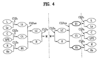
図4は、部分空間情報を適用するさらに他の例を概略的に示す図である。図4の左側を参照すると、チャンネル数6のマルチチャンネルオーディオ信号(左側前方チャンネルL、左側サラウンドチャンネルLS、センターチャンネルC、低周波チャンネルLFE、右側前方チャンネルR、右側サラウンドチャンネルRS)がモノダウンミックスオーディオ信号Mにダウンミックスされる順序及び空間パラメータとの関係が示されている。
(1) -3. Third example of tree structure (5-1-5 tree structure)
FIG. 4 is a diagram schematically illustrating still another example in which the partial space information is applied. Referring to the left side of FIG. 4, a multi-channel audio signal having 6 channels (left front channel L, left surround channel L S , center channel C, low frequency channel LFE, right front channel R, right surround channel R S ) is mono. The order of downmixing to the downmix audio signal M and the relationship with the spatial parameters are shown.
ツリー構造の第1例及び第2例と同様に、左側チャンネルLと左側サラウンドチャンネルLS間のダウンミックスと、センターチャンネルC及び低周波チャンネルLFE間のダウンミックス、右側チャンネルR及び右側サラウンドチャンネルRS間のダウンミックスが行われる。このような第1次ダウンミックス過程で、左側トータルチャンネルLt、センタートータルチャンネルCt、右側トータルチャンネルRtが生成され、空間パラメータはCLD1(ICC1含む)、CLD2(ICC2含む)、CLD3(ICC3含む)等(ここでのCLDx,ICCxは、ツリー構造の第1例及び第2例におけるCLDx,ICCxとは区別される)が算出される。1次ダウンミックス過程以降の2次ダウンミックス過程では、左側トータルチャンネルLt、センタートータルチャンネルCt及び右側トータルチャンネルRtがダウンミックスされて左側センターチャンネルLC及び右側チャンネルRが生成され、空間パラメータはCLDTTT(ICCTTT含む)が算出される。その後、第3次ダウンミックス過程で左側センターチャンネルLCと右側チャンネルRがダウンミックスされてモノダウンミックスチャンネルMが生成され、空間パラメータはCLD0(ICC0含む)が算出される。 Similar to the first and second examples of a tree structure, and downmixing between the left channel L and the left surround channel L S, downmixing between the center channel C and the low frequency channel LFE, right channel R and the right surround channel R Downmixing between S is performed. In such a first downmix process, a left total channel L t , a center total channel C t , and a right total channel R t are generated, and spatial parameters are CLD 1 (including ICC 1 ) and CLD 2 (including ICC 2 ). , CLD 3 (including ICC 3 ), etc. (CLD x and ICC x here are distinguished from CLD x and ICC x in the first and second examples of the tree structure). In the secondary downmix process after the primary downmix process, the left total channel L t , the center total channel C t and the right total channel R t are downmixed to generate the left center channel LC and the right channel R, and the spatial parameters CLD TTT (including ICC TTT ) is calculated. Thereafter, in the third downmix process, the left center channel LC and the right channel R are downmixed to generate a mono downmix channel M, and the spatial parameter CLD 0 (including ICC 0 ) is calculated.
図4の右側に示すように、部分空間情報が空間パラメータ(CLD1、CLD2、CLD3、CLDTTT、CLD0等)のうちCLD0及びCLDTTTである場合、左側トータルチャンネルLt、センタートータルチャンネルCt、右側トータルチャンネルRtを生成した後、出力チャンネルオーディオ信号として左側トータルチャンネルLt及び右側トータルチャンネルRtを選択すると、2チャンネルの出力チャンネルオーディオ信号Lt,Rtを生成でき、出力チャンネルオーディオ信号として左側トータルチャンネルLt、センタートータルチャンネルCt及び右側トータルチャンネルRtを選択すると、3チャンネルの出力チャンネルオーディオ信号Lt,Ct,Rtを生成できる。また、部分空間情報が追加的にCLD2を含む場合、センターチャンネルC及び低周波チャンネルLFEまでアップミックスした後、出力チャンネルオーディオ信号として左側トータルチャンネルLt、右側トータルチャンネルRt、センターチャンネルC及び低周波チャンネルLFEを選択すると、4チャンネルの出力チャンネルオーディオ信号Lt,Rt,C、LFEを生成できる。 As shown on the right side of FIG. 4, when the subspace information is CLD 0 and CLD TTT among the spatial parameters (CLD 1 , CLD 2 , CLD 3 , CLD TTT , CLD 0 etc.), the left total channel L t , center After generating the total channel C t and the right total channel R t , if the left total channel L t and the right total channel R t are selected as output channel audio signals, two channels of output channel audio signals L t and R t can be generated. When the left total channel L t , the center total channel C t and the right total channel R t are selected as the output channel audio signals, three channel output channel audio signals L t , C t and R t can be generated. When the subspace information additionally includes CLD 2 , after upmixing to the center channel C and the low frequency channel LFE, the left total channel L t , the right total channel R t , the center channel C and the output channel audio signal are output. When the low frequency channel LFE is selected, four channels of output channel audio signals L t , R t , C, and LFE can be generated.
以上、3種類のツリー構造を取り上げて空間パラメータの一部のみを適用して出力チャンネルオーディオ信号を生成する過程について説明したが、上記のように部分空間情報を適用するのに留まらず、その以降にさらに、組合せ空間情報を適用したり拡大空間情報を適用したりしても良い。このようにオーディオ信号に変形空間情報を適用する過程は、順次的・階層的に行われても良いが、一括的で且つ統合的に処理されても良い。 As described above, the process of generating the output channel audio signal by applying only a part of the spatial parameters by taking up the three kinds of tree structures has been described. Furthermore, combination space information or expanded space information may be applied. As described above, the process of applying the deformed space information to the audio signal may be performed sequentially and hierarchically, or may be processed collectively and collectively.
(2)組合せ空間情報
空間情報は、マルチチャンネルオーディオ信号が定められたツリー構造にしたがってダウンミックスされる過程で計算されたものであるから、ダウンミックスオーディオ信号を、空間情報の空間パラメータをそのまま用いてデコーディングすると、ダウンミックスされる前の元来のマルチチャンネルオーディオ信号に復元される。もし、マルチチャンネルオーディオ信号のチャンネル数Mが出力チャンネルオーディオ信号のチャンネル数Nと異なる場合、空間情報を組み合わせて新しい組合せ空間情報を生成した後、これを用いてダウンミックスオーディオ信号をアップミックスできる。具体的に、空間パラメータを変換公式に代入し、組合せ空間パラメータを生成できる。
(2) Combination spatial information Since the spatial information is calculated in the process of downmixing the multi-channel audio signal according to a defined tree structure, the spatial parameter of the spatial information is used as it is for the downmix audio signal. Decoding, the original multichannel audio signal before being downmixed is restored. If the number M of channels of the multi-channel audio signal is different from the number N of channels of the output channel audio signal, after combining the spatial information to generate new combined spatial information, the downmix audio signal can be upmixed using this. Specifically, a spatial parameter can be substituted into a conversion formula to generate a combined spatial parameter.
このような方法は、エンコーディング装置でマルチチャンネルオーディオ信号がダウンミックスされる順序と方法によって変わることができるが、このダウンミックスされる順序と方法は、空間情報のツリー構造情報を用いて照会すれば良い。また、このような方法は、出力チャンネルの本数がいくつかによって変わることができるが、出力チャンネルの本数などは、出力チャンネル情報を用いて照会すれば良い。 Such a method can be changed according to the order and method in which the multi-channel audio signal is downmixed in the encoding device. The order and method in which the multichannel audio signal is downmixed can be inquired by using the tree structure information of the spatial information. good. Also, in this method, the number of output channels can vary depending on some, but the number of output channels and the like may be inquired using the output channel information.
以下では、空間情報を変形する方法の具体的な実施例について説明し、続いて、仮想3D効果を与えるための実施例についても説明する。 In the following, a specific example of a method for transforming spatial information will be described, and then an example for providing a virtual 3D effect will also be described.
(2)−1.一般的な組合せ空間情報
空間情報の空間パラメータを組み合わせて組合せ空間パラメータを生成する方法は、ダウンミックス過程におけるツリー構造とは異なるツリー構造によってアップミックスするためのものであるから、ツリー構造情報によるツリー構造が何であろうとも、全てのダウンミックスオーディオ信号に適用可能である。
(2) -1. General combination space information A method for generating a combination space parameter by combining spatial parameters of spatial information is for upmixing with a tree structure different from the tree structure in the downmix process. Whatever the structure, it is applicable to all downmix audio signals.
マルチチャンネルオーディオ信号が5.1チャンネルで、ダウンミックスオーディオ信号が1チャンネル(モノチャンネル)の場合、2チャンネルの出力チャンネルオーディオ信号を生成する過程について、下記の2つの例に挙げて説明する。 When the multi-channel audio signal is 5.1 channel and the downmix audio signal is 1 channel (mono channel), the process of generating the 2-channel output channel audio signal will be described with reference to the following two examples.
(2)−1−1.ツリー構造の第4例(5−1−51ツリー構造)
図5は、組合せ空間情報を適用する一例を概略的に示す図である。図5の左側に示すように、5.1チャンネルのマルチチャンネルオーディオ信号がダウンミックスされる過程で算出できる空間パラメータはそれぞれ、CLD0乃至CLD4、及びICC0乃至ICC4(図示せず)といえる。例えば、空間パラメータのうち、左側チャンネル信号Lと右側チャンネル信号Rのチャンネル間レベル差はCLD3で、チャンネル間相関関係はICC3であり、左側サラウンドチャンネルLS及び右側サラウンドチャンネルRSのチャンネル間レベル差はCLD2で、チャンネル間相関関係はICC2である。
(2) -1-1. Fourth example of tree structure (5-1-5 1 tree structure)
FIG. 5 is a diagram schematically illustrating an example of applying the combination space information. As shown on the left side of FIG. 5, spatial parameters that can be calculated in the process of downmixing the 5.1 channel multi-channel audio signal are CLD 0 to CLD 4 , and ICC 0 to ICC 4 (not shown), respectively. I can say that. For example, among the spatial parameters, the inter-channel level difference between the left channel signal L and the right channel signal R is CLD 3 , the inter-channel correlation is ICC 3 , and the inter-channel levels of the left surround channel LS and the right surround channel RS The difference is CLD 2 and the inter-channel correlation is ICC 2 .
これに対し、図5の右側を参照すると、モノダウンミックスオーディオ信号mに組合せ空間パラメータCLDα,ICCαを適用して左側チャンネル信号Lt及び右側チャンネル信号Rtを生成すると、モノチャンネルオーディオ信号mから直接ステレオ出力チャンネルオーディオ信号Lt,Rtを生成することができる。ここでの組合せ空間パラメータCLDα,ICCαは、空間パラメータCLD0乃至CLD4、及びICC0乃至ICC4を組み合わせて計算することができる。まず、空間パラメータのうち、CLD0乃至CLD4を組み合わせて組合せ空間パラメータの中CLDαを計算する過程について説明した後、空間パラメータのうち、CLD0乃至CLD4及びICC0乃至ICC4を組み合わせて組合せ空間パラメータの中ICCαを計算する過程について説明する。 On the other hand, referring to the right side of FIG. 5, when the combination channel parameters CLD α and ICC α are applied to the mono downmix audio signal m to generate the left channel signal L t and the right channel signal R t , the mono channel audio signal The stereo output channel audio signals L t and R t can be generated directly from m. The combination space parameters CLD α and ICC α here can be calculated by combining the space parameters CLD 0 to CLD 4 and ICC 0 to ICC 4 . First, the process of calculating CLD α in the combination spatial parameters by combining CLD 0 to CLD 4 among the spatial parameters will be described, and then CLD 0 to CLD 4 and ICC 0 to ICC 4 among the spatial parameters are combined. A process of calculating ICC α in the combination space parameter will be described.
(2)−1−1−a.CLDαの誘導
まず、CLDαは、左側出力信号Lt及び右側出力信号Rt間のレベル差であるから、CLDの定義式に左側出力信号Lt及び右側出力信号Rtを代入すると、次の通りになる。
(2) -1-1-a. CLD induction of alpha First, the CLD alpha, because the level difference between the left output signal L t and a right output signal R t, and substituting the left output signal L t and a right output signal R t in the definition formula of CLD, following It becomes as follows.

CLDαは、上記式1または式2のように定義される。
CLD α is defined as in
一方、PLt及びPRtを空間パラメータCLD0乃至CLD4を用いて表現するためには、出力チャンネルオーディオ信号の左側出力信号Lt、右側出力信号Rt及びマルチチャンネル信号L,Ls,R,Rs,C,LFEとの関係式が必要であり、その関係式は次のように定義できる。 On the other hand, in order to express P Lt and P Rt using the spatial parameters CLD 0 to CLD 4 , the left output signal L t , the right output signal R t, and the multi-channel signals L, L s , R of the output channel audio signal. , R s , C, and LFE are necessary, and the relation can be defined as follows.
式3のような関係式は、出力チャンネルオーディオ信号をどのように定義するかによって変わることができるので、式3とは異なる式でも定義できることは当然である。例えば、式3で、C/√2またはLFE/√2での1/√2因子が、‘0’にも‘1’にもなりうる。
Since the relational expression such as
式3から下記の式4のような関係式が誘導されることができる。
A relational expression such as the following
CLDαが式1(または、式2)によってPLt及びPRtを用いて表現されることができ、このようなPLt及びPRtは式4によってPL,PLs,PC,PLFE,PR,PRsを用いて表現されることができるので、PL,PLs,PC,PLFE,PR,PRsを空間パラメータCLD0乃至CLD4を用いて表現できる関係式を求める必要がある。
CLD α can be expressed using P Lt and P Rt according to Formula 1 (or Formula 2), and such P Lt and P Rt can be expressed as P L , P Ls , P C , P LFE according to
一方、図5のようなツリー構造の場合、マルチチャンネルオーディオ信号L、R、C、LFE、Ls、Rs及びモノダウンミックスチャンネル信号mの関係は、次の通りになる。 On the other hand, in the case of the tree structure as shown in FIG. 5, the relationship among the multi-channel audio signals L, R, C, LFE, L s , R s and the mono downmix channel signal m is as follows.
式5から、次の式6の関係式が誘導されることができる。
From
すなわち、式6を式4に代入し、式4を式1(または、式2)に代入することで、組合せ空間パラメータであるCLDαは、空間パラメータであるCLD0乃至CLD4を組み合わせて表現することができる。
That is, by substituting
一方、式4におけるPC/2+PLFE/2に式6を代入した展開式は、次の通りである。
On the other hand, the expansion formula obtained by substituting
したがって、式7は、次のように簡単にすることができる。
Therefore,
要するに、式8及び式6を式4に代入し、式4を式1に代入することによって、組合せ空間パラメータであるCLDαは、空間パラメータであるCLD0乃至CLD4を組み合わせる方式で表現されることができる。
In short, by substituting
(2)−1−1−b.ICCαの誘導
まず、ICCαは、左側出力信号Lt及び右側出力信号Rt間の相関関係であるから、その定義式に左側出力信号Lt及び右側出力信号Rtを代入すると、次の通りになる。
(2) -1-1-b. Induction of ICC alpha First, the ICC alpha, because it is the correlation between the left output signal L t and a right output signal R t, and substituting the left output signal L t and a right output signal R t in the defining equation, the following It becomes street.
式9で、PLt、PRtは、式4、式6、及び式8によってCLD0乃至CLD4を用いて表現することができ、PLtPRtは、次の式10のように展開することができる。
In
式10で、PC/2+PLFE/2は、式6によってCLD0乃至CLD4で表現されることができ、PLRとPLsRsは、ICC定義によって次のように展開することができる。
In
式11で、√(PLPR)(または、√(PLsPRs))を移項すると、次の式12となる。 In equation 11, when √ (P L P R ) (or √ (P Ls P Rs )) is transferred, the following equation 12 is obtained.
式12で、PL,PR,PLs,PRsはそれぞれ、式6によってCLD0乃至CLD4で表現されることができる。式6を式12に代入すると、次の式13のようになる。
In Expression 12, P L , P R , P Ls , and P Rs can be expressed as CLD 0 to CLD 4 according to
要するに、式6及び式13を式10に代入し、式10及び式4を式9に代入することで、組合せ空間パラメータであるICCαは、空間パラメータであるCLD0乃至CLD3及びICC2、ICC3で表現されることができる。
In short, by substituting
(2)−1−2.ツリー構造の第5例(5−1−52ツリー構造)
図6は、組合せ空間情報を適用する他の例を概略的に示す図である。図6の左側に示すように、5.1チャンネルのマルチチャンネルオーディオ信号がダウンミックスされる過程で算出できる空間パラメータはそれぞれ、CLD0乃至CLD4、及びICC0乃至ICC4(図示せず)といえる。空間パラメータのうち、左側チャンネル信号Lと左側サラウンドチャンネル信号Lsのチャンネル間レベル差はCLD3で、チャンネル間相関関係はICC3であり、右側チャンネルR及び右側サラウンドチャンネルRSのチャンネル間レベル差はCLD4で、チャンネル間相関関係はICC4である。
(2) -1-2. Fifth example of tree structure (5-1-5 2- tree structure)
FIG. 6 is a diagram schematically illustrating another example in which the combination space information is applied. As shown on the left side of FIG. 6, the spatial parameters that can be calculated in the process of downmixing the 5.1 channel multi-channel audio signal are CLD 0 to CLD 4 and ICC 0 to ICC 4 (not shown), respectively. I can say that. Among the spatial parameters, the inter-channel level difference between the left channel signal L and the left surround channel signal L s is CLD 3 , the inter-channel correlation is ICC 3 , and the inter-channel level difference between the right channel R and the right surround channel RS Is CLD 4 and the inter-channel correlation is ICC 4 .
これに対し、図6の右側を参照すると、モノダウンミックスオーディオ信号mに組合せ空間パラメータCLDβ,ICCβを適用して左側チャンネル信号Lt及び右側チャンネル信号Rtを生成すると、モノチャンネルオーディオ信号mから直接ステレオ出力チャンネルオーディオ信号Lt,Rtを生成することができる。ここでの組合せ空間パラメータCLDβ,ICCβは、空間パラメータCLD0乃至CLD4、及びICC0乃至ICC4を用いて計算できる。まず、空間パラメータのうちCLD0乃至CLD4を用いて、組合せ空間パラメータのうちCLDβを計算する過程について説明し、続いて、空間パラメータのうちCLD0乃至CLD4及びICC0乃至ICC4を用いて、組合せ空間パラメータのうちICCβを計算する過程について説明する。 On the other hand, referring to the right side of FIG. 6, when the combination channel parameters CLD β and ICC β are applied to the mono downmix audio signal m to generate the left channel signal L t and the right channel signal R t , the mono channel audio signal The stereo output channel audio signals L t and R t can be generated directly from m. Here, the combination space parameters CLD β and ICC β can be calculated using the space parameters CLD 0 to CLD 4 and ICC 0 to ICC 4 . First, a process of calculating CLD β among the combination spatial parameters using CLD 0 to CLD 4 among the spatial parameters will be described, and subsequently, CLD 0 to CLD 4 and ICC 0 to ICC 4 among the spatial parameters will be used. The process of calculating ICC β among the combination space parameters will be described.
(2)−1−2−a.CLDβの誘導
まず、CLDβは、左側出力信号Lt及び右側出力信号Rt間のレベル差であるから、その定義式に左側出力信号Lt及び右側出力信号Rtを代入すると、次の通りになる。
(2) -1-2-a. CLD induction of beta First, the CLD beta, since the level difference between the left output signal L t and a right output signal R t, and substituting the left output signal L t and a right output signal R t in the defining equation, the following It becomes street.
CLDβは、上記の式14または式15のように定義される。
CLD β is defined as in Equation 14 or Equation 15 above.
一方、PLt及びPRtを空間パラメータCLD0乃至CLD4を用いて表現するためには、出力チャンネルオーディオ信号の左側出力信号Lt、右側出力信号Rt及びマルチチャンネル信号L、Ls、R、Rs、C、LFEとの関係式が必要であり、その関係式は、式3と同様に次のように定義されることができる。
On the other hand, in order to express P Lt and P Rt using the spatial parameters CLD 0 to CLD 4 , the left output signal L t , the right output signal R t, and the multi-channel signals L, L s , R of the output channel audio signal. , R s , C, and LFE are necessary, and the relational expression can be defined as follows in the same manner as
式16のような関係式は出力チャンネルオーディオ信号をどのように定義するかによって変わることができるもので、よって、他の式でも定義できることは当然である。例えば、C/√2またはLFE/√2因子における1/√2が0にも1にもなりうる。 The relational expression such as Expression 16 can be changed depending on how the output channel audio signal is defined. Therefore, it is natural that other expressions can be defined. For example, 1 / √2 in the C / √2 or LFE / √2 factor can be 0 or 1.
式16から次の式17のような関係式が誘導されることができる。 A relational expression such as the following Expression 17 can be derived from Expression 16.
式14(または、式15)で、CLDβがPLt及びPRtを用いて表現可能であり、PLt及びPRtは、式15でPL、PLs、PC、PLFE、PR、PRsを用いて表現可能なので、PL、PLs、PC、PLFE、PR、PRsを、空間パラメータCLD0乃至CLD4を用いて表現できる関係式を求める必要がある。 Formula 14 (or Formula 15), CLD beta is representable using P Lt and P Rt, P Lt and P Rt is, P L in Equation 15, P Ls, P C, P LFE, P R since representable using P Rs, P L, P Ls , P C, P LFE, P R, the P Rs, it is necessary to obtain the relational expression that can be represented using spatial parameters CLD 0 to CLD 4.
一方、図6のようなツリー構造の場合、マルチチャンネルオーディオ信号L,R,C,LFE,Ls,Rs及びモノダウンミックスチャンネル信号mの関係は、次の通りである。 On the other hand, in the case of the tree structure as shown in FIG. 6, the relationship among the multi-channel audio signals L, R, C, LFE, L s , R s and the mono downmix channel signal m is as follows.
式18から、次の式19のような関係式が誘導されることができる。 From equation 18, a relational expression such as the following equation 19 can be derived.
すなわち、式19を式17に代入し、式17を式14(または、式15)に代入することで、組合せ空間パラメータであるCLDβは、空間パラメータであるCLD0乃至CLD4を組み合わせる方式で表現されることができる。 That is, by substituting Equation 19 into Equation 17 and Equation 17 into Equation 14 (or Equation 15), CLD β which is a combination space parameter is a method in which CLD 0 to CLD 4 which are space parameters are combined. Can be expressed.
一方、式19を式17におけるPL+PLsに代入した展開式は、次の通りである。 On the other hand, the expansion equation obtained by substituting Equation 19 into P L + P Ls in Equation 17 is as follows.
ここで、c1及びc2の定義によれば(式5参照)、(c1,x)2+(c2,x)2=1なので、(c1,OTT3)2+(c2,OTT3)2=1である。 Here, according to the definition of c 1 and c 2 (see Equation 5), since (c 1, x ) 2 + (c 2, x ) 2 = 1, (c 1, OTT3 ) 2 + (c 2, OTT3 ) 2 = 1.
したがって、式20は、次のように簡単にすることができる。 Therefore, Equation 20 can be simplified as follows.
一方、式19を式17におけるPR+PRsに代入した展開式は、次の通りである。 On the other hand, the expansion formula obtained by substituting Formula 19 for P R + P Rs in Formula 17 is as follows.
ここで、c1及びc2の定義によれば(式5参照)、(c1,x)2+(c2,x)2=1なので、(c1,OTT4)2+(c2,OTT4)2=1である。 Here, according to the definition of c 1 and c 2 (see Equation 5), since (c 1, x ) 2 + (c 2, x ) 2 = 1, (c 1, OTT4 ) 2 + (c 2, OTT4 ) 2 = 1.
したがって、式22は、次のように簡単にすることができる。 Therefore, Equation 22 can be simplified as follows.
一方、式19を式17におけるPC/2+PLFE/2に代入した展開式は、次の通りである。 On the other hand, the expansion formula obtained by substituting Formula 19 into P C / 2 + P LFE / 2 in Formula 17 is as follows.
したがって、式24は、次のように簡単にすることができる。
要するに、式21、式23及び式25を式17に代入し、式17を式14(または、式15)に代入することで、組合せ空間パラメータであるCLDβは、空間パラメータであるCLD0乃至CLD4を組み合わせる方式で表現されることができる。 In short, by substituting Equation 21, Equation 23, and Equation 25 into Equation 17, and assigning Equation 17 into Equation 14 (or Equation 15), CLD β , which is a combinational space parameter, becomes CLD 0 to CLD, which are space parameters. It can be expressed in a manner that combines CLD 4 .
(2)−1−2−b.ICCβの誘導
まず、ICCβは、左側出力信号Lt及び右側出力信号Rt間の相関関係であるから、その定義式に左側出力信号Lt及び右側出力信号Rtを代入すると、次の通りになる。
(2) -1-2-b. Induction of ICC beta First, the ICC beta, because it is the correlation between the left output signal L t and a right output signal R t, and substituting the left output signal L t and a right output signal R t in the defining equation, the following It becomes street.
式26で、PLt、PRtは、式19によってCLD0乃至CLD4を用いて表現することができ、PLtPRtは、次の式27のように展開することができる。 In Expression 26, P Lt and P Rt can be expressed using CLD 0 to CLD 4 according to Expression 19, and P Lt P Rt can be expanded as in Expression 27 below.
式27で、PC/2+PLFE/2は、式19によってCLD0乃至CLD4で表現されることができ、PL_R_は、ICC定義によって次のように展開することができる。 In Equation 27, P C / 2 + P LFE / 2 can be expressed as CLD 0 to CLD 4 according to Equation 19, and P L_R_ can be expanded as follows according to the ICC definition.
√(PL_PR_)を移項すると、次の式29のようになる。 When √ (P L_P R_ ) is shifted, the following Expression 29 is obtained.
式29で、PL_、PR_はそれぞれ、式21及び式23によってCLD0乃至CLD4で表現されることができる。式21及び式23を式29に代入すると、次の式30となる。 In Expression 29, P L_ and PR_ can be expressed as CLD 0 to CLD 4 according to Expression 21 and Expression 23, respectively. When Expression 21 and Expression 23 are substituted into Expression 29, the following Expression 30 is obtained.
要するに、式30を式27に代入し、式27及び式17を式26に代入することで、組合せ空間パラメータであるICCβは、空間パラメータであるCLD0乃至CLD4及びICC1を組み合わせる方式で表現されることができる。 In short, by substituting equation 30 into equation 27 and substituting equation 27 and equation 17 into equation 26, ICC β that is a combination space parameter is a method that combines CLD 0 to CLD 4 and ICC 1 that are space parameters. Can be expressed.
上記の空間パラメータを変形する方法は一実施例で、上記の式は、PxまたはPxyを求めるにおいて、信号エネルギーの他、各チャンネル間の相関関係(例:ICC0等)をさらに考慮することによって様々な形態に変わることができる。 The above-described method of transforming the spatial parameter is an example, and the above formula further considers the correlation between channels (eg, ICC 0 etc.) in addition to the signal energy in determining P x or P xy. It can change into various forms depending on the situation.
(2)−2.サラウンド効果を持つ組合せ空間情報
空間情報を組み合わせて組合せ空間情報を生成するに当たり、音響経路を考慮すると、仮想サラウンド効果を出すことができる。仮想サラウンド効果または仮想3D効果とは、実際にはサラウンドチャンネルのスピーカーがないにもかかわらず、ドサラウンドチャンネルのスピーカーがあるかのような効果を出すことで、例えば、2個のステレオスピーカーを介して5.1チャンネルオーディオ信号を出力することである。
(2) -2. Combination spatial information having a surround effect When generating a combination space information by combining spatial information, a virtual surround effect can be produced by considering an acoustic path. The virtual surround effect or the virtual 3D effect is an effect in which there is a speaker of a do surround channel even though there is actually no surround channel speaker, for example, via two stereo speakers. This is to output a 5.1 channel audio signal.
音響経路は空間フィルタ情報とすることができ、空間フィルタ情報は、HRTF(Head−Related Tranfer Function)と呼ばれる関数を用いれば良いが、本発明がこれに限定されることはない。空間フィルタ情報は、フィルタパラメータを含むことができ、このフィルタパラメータ及び空間パラメータを変換公式に代入して組合せ空間パラメータを生成することができる。一方、生成された組合せ空間パラメータは、フィルタ係数(filter coefficients)を含むことができる。 The acoustic path may be spatial filter information, and the spatial filter information may use a function called HRTF (Head-Related Transfer Function), but the present invention is not limited to this. The spatial filter information can include a filter parameter, and the combined spatial parameter can be generated by substituting the filter parameter and the spatial parameter into a conversion formula. Meanwhile, the generated combination space parameter may include filter coefficients.
以下では、マルチチャンネルオーディオ信号が5チャンネルで、3チャンネルの出力チャンネルオーディオ信号を生成する場合を取り上げ、サラウンド効果を持つ組合せ空間情報を生成するために音響経路を考慮する方法について説明する。 Hereinafter, a case where the multi-channel audio signal is five channels and a three-channel output channel audio signal is generated will be described, and a method of considering an acoustic path in order to generate combination spatial information having a surround effect will be described.
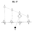
図7は、3チャンネルのスピーカーの位置、及び、スピーカーと聴き手までの音響経路を示す図である。図7を参照すると、3個のスピーカーSPK1,SPK2,SPK3の位置がそれぞれ、左側前L、センターC、右側Rであり、仮想サラウンドチャンネルの位置が左側サラウンドLs及び右側サラウンドRsであることがわかる。3個のスピーカーの位置L,C,R、及び、仮想サラウンドチャンネルの位置Ls,Rsから聴き手の左耳の位置l、聴き手の右耳の位置rに至るまでの音響経路が表示されている。
Gx_yは、x位置からy位置に至る音響経路を表示する。例えば、GL_rは、左側前方の位置Lから聴き手の右耳の位置rに至る音響経路を表す。
FIG. 7 is a diagram showing the positions of the three-channel speakers and the acoustic paths to the speakers and the listener. Referring to FIG. 7, it can be seen that the positions of the three speakers SPK1, SPK2, and SPK3 are the left front L, the center C, and the right R, respectively, and the virtual surround channel positions are the left surround Ls and the right surround Rs. . The acoustic paths from the positions L, C, R of the three speakers and the positions Ls, Rs of the virtual surround channel to the
G x_y displays an acoustic path from the x position to the y position. For example, GL_r represents an acoustic path from the left front position L to the right ear position r of the listener.
もし、5つの位置にスピーカーが存在(すなわち、左側サラウンド(Ls)及び右側サラウンド(Rs)にもスピーカーが存在)し、聴き手が図7に示す位置に存在すると、聴き手の左耳に流入する信号L0及び聴き手の右耳に流入する信号R0は、次の通りである。 If there are speakers in five positions (ie, speakers in left surround (Ls) and right surround (Rs) as well) and the listener is in the position shown in FIG. 7, it flows into the listener's left ear The signal L 0 to be transmitted and the signal R 0 flowing into the right ear of the listener are as follows.
ここで、L,C,R,Ls,Rsは、各位置のチャンネルを表し、Gx_yは、x位置からy位置に至る音響経路を表し、*はコンボリューションを表す。 Here, L, C, R, Ls, and Rs represent channels at respective positions, G x_y represents an acoustic path from the x position to the y position, and * represents convolution.
しかし、上に言及したように、3つの位置L,C,Rにのみスピーカーが存在する場合、聴き手の左耳に流入する信号L0_real及び聴き手の右耳に流入する信号R0_realは、次の通りになる。 However, as mentioned above, if there are speakers only at the three positions L, C, R, the signal L 0_real flowing into the listener's left ear and the signal R 0_real flowing into the listener's right ear are It will be as follows.
式32に表示された信号は、サラウンドチャンネル信号Ls,Rsが考慮されないので、仮想サラウンド効果を出すことができない。仮想サラウンド効果を出すためには、左側サラウンドチャンネル信号Lsが元の位置Lsから出力されて聴き手の位置l,rに到達する時の信号と、元の位置Ls,Rsでない3つの位置L,C,Rのスピーカーを介して出力し、聴き手の位置l,rに到達する信号と同じくすれば良い。右側サラウンドチャンネル信号Rsの場合も同様である。 Since the surround channel signals Ls and Rs are not considered in the signal displayed in Expression 32, a virtual surround effect cannot be produced. In order to produce a virtual surround effect, a signal when the left surround channel signal Ls is output from the original position Ls and reaches the listener's positions l and r, and three positions L, which are not the original positions Ls and Rs. What is necessary is just to make it the same as the signal which outputs via the speaker of C and R and arrives at listener's position l and r. The same applies to the right surround channel signal Rs.
まず、左側サラウンドチャンネル信号Lsについて説明すると、左側サラウンドチャンネル信号Lsが元の位置である左側サラウンド位置Lsのスピーカーから出力される場合、聴き手の左耳l及び聴き手の右耳rに到達する信号はそれぞれ次の通りである。 First, the left surround channel signal Ls will be described. When the left surround channel signal Ls is output from the speaker at the left surround position Ls which is the original position, the left surround channel signal Ls reaches the listener's left ear l and the listener's right ear r. The signals are as follows.
また、右側サラウンドチャンネル信号Rsが元の位置である右側サラウンド位置Rsのスピーカーから出力される場合、聴き手の左耳l及び聴き手の右耳rに到達する信号はそれぞれ、次の通りである。 When the right surround channel signal Rs is output from the speaker at the right surround position Rs, which is the original position, the signals reaching the listener's left ear l and the listener's right ear r are as follows. .
聴き手の左耳l及び聴き手の右耳rに到達する信号が式33及び式34の成分と同じなら、どんな位置のスピーカーから出力されるとしても(例えば、左側前方位置のスピーカーSPK1等から出力されるとしても)、聴き手は、左側サラウンドの位置Ls及び右側サラウンドの位置Rsにスピーカーが存在するかのように感じることができる。 If the signals reaching the listener's left ear l and listener's right ear r are the same as the components of Equation 33 and Equation 34, they can be output from any position speaker (for example, from the speaker SPK1 at the left front position). The listener can feel as if there are speakers at the left surround position Ls and the right surround position Rs.
一方、式33に表示された成分は、左側サラウンド位置Lsのスピーカーから出力される場合、それぞれ聴き手の左耳l及び聴き手の右耳rに到達する信号であるので、式33に表示された成分そのままに左側前方位置のスピーカーSPK1から出力すると、それぞれ聴き手の左耳l及び聴き手の右耳rに到達する信号は、次の通りになる。
On the other hand, the components displayed in Expression 33 are signals that reach the left ear l of the listener and the right ear r of the listener when output from the speaker at the left surround position Ls. When the component SP is output from the left front speaker SPK1, the signals reaching the listener's
式35では、左側前方位置Lから聴き手の左耳l(または、右耳r)までの音響経路に該当する成分である‘GL_l’(または、‘GL_r’)が追加される。しかし、聴き手の左耳l及び聴き手の右耳rに到達する信号は、式35に表示された成分ではなく式33に表示された成分でなければならない。このため、左側前位置Lのスピーカーから出力して聴き手に到達する場合、‘GL_l’(または、‘GL_r’)成分が追加されるため、式33に表された成分を左側前方位置LのスピーカーSPK1から出力する場合には、音響経路に‘GL_l’(または、‘GL_r’)の逆関数‘GL_l −1’(または、‘GL_r −1’)を考慮しなければならない。言い換えると、式33に該当する成分を左側前方位置LのスピーカーSPK1から出力する場合、次の式のように変形されなければならない。 In Expression 35, ' GL_l ' (or ' GL_r ') that is a component corresponding to the acoustic path from the left front position L to the listener's left ear l (or right ear r) is added. However, the signal arriving at the listener's left ear l and listener's right ear r must be the component displayed in equation 33, not the component displayed in equation 35. For this reason, when the output from the speaker at the left front position L reaches the listener, the ' GL_l ' (or ' GL_r ') component is added, so that the component represented by Equation 33 is changed to the left front position. If the output from the L speaker SPK1 is, 'G L_l' (or, 'G L_r') to the acoustic path inverse function of 'G L_l -1' (or, 'G L_r -1') to be taken into consideration Don't be. In other words, when the component corresponding to Expression 33 is output from the speaker SPK1 at the left front position L, it must be transformed as the following expression.
そして、式34に該当する成分を左側前方位置LのスピーカーSPK1から出力する場合、次の式のように変形されなければならない。 When a component corresponding to Expression 34 is output from the speaker SPK1 at the left front position L, it must be transformed as the following expression.
したがって、左側前方位置LのスピーカーSPK1から出力される信号L’は、次のようにまとめることができる。 Therefore, the signal L ′ output from the speaker SPK1 at the left front position L can be summarized as follows.
式38に表示された信号が、左側前方位置のスピーカーSPK1から出力されて聴き手の左耳l位置に到達すると、音響経路‘GL_l’ファクターが追加されるので、式38における‘GL_l −1’項が相殺され、結果として式33及び式34に表示されたファクターが残る。 When the signal displayed in Expression 38 is output from the speaker SPK1 at the left front position and reaches the position of the listener's left ear l, the acoustic path ' GL_l ' factor is added, so that ' GL_l − in Expression 38 The 1 'term is canceled, resulting in the factors displayed in Equation 33 and Equation 34 remaining.
図8は、仮想サラウンド効果のために各位置から出力される信号を示す図である。 FIG. 8 is a diagram illustrating signals output from each position for the virtual surround effect.
図8を参照すると、サラウンドの位置Ls,Rsから出力される信号Ls,Rsを、音響経路を考慮し、各スピーカー位置SPK1から出力される信号L’に含めると、式38のようになることがわかる。 Referring to FIG. 8, when the signals Ls and Rs output from the surround positions Ls and Rs are included in the signal L ′ output from each speaker position SPK1 in consideration of the acoustic path, Equation 38 is obtained. I understand.
式38で、GLs_l*GL_l −1をHLs_Lで簡略に表示すると、次の通りになる。 In Equation 38, when G Ls — l * G L — l −1 is simply displayed as HL s_L , the result is as follows.
一方、センター位置CのスピーカーSPK2から出力される信号C’を、次のようにまとめることができる。 On the other hand, the signal C ′ output from the speaker SPK2 at the center position C can be summarized as follows.
一方、右側前方位置RのスピーカーSPK3から出力される信号R’は、次のようにまとめることができる。 On the other hand, the signal R ′ output from the speaker SPK3 at the right front position R can be summarized as follows.
図9は、式38、式39、及び式40のように5チャンネル信号を用いて3チャンネル信号を生成する方法を概念的に示す図である。5チャンネル信号を用いて2チャンネル信号R’,L’を生成したり、サラウンドチャンネル信号Ls,Rsをセンターチャンネル信号C’に含めない場合、HLs_C及びHRs_Cは0となる。 FIG. 9 is a diagram conceptually illustrating a method of generating a three-channel signal using a five-channel signal as in Expression 38, Expression 39, and Expression 40. When the two-channel signals R ′ and L ′ are generated using the five-channel signal or the surround channel signals Ls and Rs are not included in the center channel signal C ′, HLs_C and HRs_C are 0.
実装の便宜のためにHx_yの代わりにGx_yを使用しても良く、クロストーク(cross−talk)を考慮してHx_yを用いても良い等、Hx_yは様々な変形形態になりうる。 May be used G x_y instead of H x_y for implementation convenience, may be employed H x_y considering crosstalk (cross-talk) or the like, H x_y may be in a variety of variations .
上記の説明は、サラウンド効果を持つ組合せ空間情報の一例で、空間フィルタ情報の適用方法によって様々な形態に変形できることは自明である。上述の過程を通じてスピーカーから出力される信号(上の例では、左側前方チャンネルL’、右側前方チャンネルR’、センターチャンネルC’)は、前述したように、組合せ空間情報の中でも特に組合せ空間パラメータを用いてダウンミックスオーディオ信号から生成可能である。 The above description is an example of combined spatial information having a surround effect, and it is obvious that the spatial information can be transformed into various forms depending on the application method of spatial filter information. As described above, the signals output from the speakers through the above-described process (in the above example, the left front channel L ′, the right front channel R ′, and the center channel C ′) have combination space parameters in the combination space information, as described above. And can be generated from a downmix audio signal.
(3)拡大空間情報
空間情報に拡張空間情報を追加して拡大空間情報を生成することができる。そして、この拡大空間情報を用いてオーディオ信号をアップミキシングでき、このアップミキシングする段階は、空間情報に基づいてオーディオ信号を1次アップミキシングオーディオ信号に変換し、拡張空間情報に基づいて1次アップミキシングオーディオ信号を2次アップミキシングオーディオ信号に変換する。
(3) Expanded spatial information Expanded spatial information can be generated by adding expanded spatial information to the spatial information. The audio signal can be upmixed using the expanded spatial information. The upmixing step converts the audio signal into a primary upmixed audio signal based on the spatial information, and performs a primary up based on the extended spatial information. The mixing audio signal is converted into a secondary upmixing audio signal.
ここで、拡張空間情報は、拡張チャンネル構成情報、拡張チャンネルマッピング情報及び拡張空間パラメータを含むことができる。拡張チャンネル構成情報とは、空間情報のツリー構造情報によって構成できるチャンネル以外に、構成できるチャンネルに関する情報のことで、分割識別子及び未分割識別子のうち一つ以上を含むことができる。これについての具体的な説明は後述される。拡張チャンネルマッピング情報は、拡張チャンネルを構成する各チャンネルの位置情報である。拡張空間パラメータは、1チャンネルが2以上のチャンネルにアップミックスされるのに必要な情報で、チャンネル間レベル差を含むことができる。 Here, the extended space information may include extended channel configuration information, extended channel mapping information, and extended space parameters. The extended channel configuration information is information about channels that can be configured in addition to the channels that can be configured by the tree structure information of the spatial information, and can include one or more of a divided identifier and an undivided identifier. A specific description thereof will be described later. The extended channel mapping information is position information of each channel constituting the extended channel. The extended space parameter is information necessary for one channel to be upmixed to two or more channels, and can include an inter-channel level difference.
このような拡張空間情報は、i)エンコーディング装置により生成されたのち、空間情報に含まれたものであっても良く、ii)デコーディング装置により自体的に生成されたものであっても良い。拡張空間情報がエンコーディング装置により生成されたものである場合、拡張空間情報の存在有無は、空間情報の指示子を基に判断されることができる。拡張空間情報がデコーディング装置により自体的に生成されたものである場合、拡張空間情報の拡張空間パラメータは、空間情報の空間パラメータを用いて計算したものであっも良い。 Such extended spatial information may be i) generated by the encoding device and then included in the spatial information, or ii) generated by the decoding device itself. When the extended spatial information is generated by the encoding device, the presence or absence of the extended spatial information can be determined based on the indicator of the spatial information. When the extended spatial information is generated by the decoding device itself, the extended spatial parameter of the extended spatial information may be calculated using the spatial parameter of the spatial information.
一方、空間情報及び拡張空間情報に基づいて生成された拡大空間情報を用いてオーディオ信号をアップミックスする過程は、順次的で階層的に行われても良いが、一括的で統合的に処理されても良い。もし、拡大空間情報が、空間情報及び拡張空間情報に基づいて一つのマトリックスとして算出可能であると、前記マトリックスを用いることによって、一括的で直接的にダウンミックスオーディオ信号をマルチチャンネルオーディオ信号にアップミックスできるわけである。この時、マトリックスを構成する因子は、空間パラメータ、及び拡張空間パラメータによって定義されたものであれば良い。 On the other hand, the process of upmixing the audio signal using the expanded spatial information generated based on the spatial information and the extended spatial information may be performed sequentially and hierarchically, but is processed collectively and collectively. May be. If the expanded spatial information can be calculated as a single matrix based on the spatial information and the extended spatial information, the downmix audio signal can be directly and collectively increased to a multi-channel audio signal by using the matrix. You can mix. At this time, the factor which comprises a matrix should just be defined by the spatial parameter and the extended spatial parameter.
まず、エンコーディング装置により生成された拡張空間情報を用いる場合について説明し、続いて、デコーディング装置で拡張空間情報を自体的に生成する場合について説明する。 First, a case where extended space information generated by an encoding device is used will be described, and then a case where extended space information is generated by the decoding device itself will be described.
(3)−1:エンコーディング装置により生成された拡張空間情報を用いる場合:任意ツリー構造(arbitrary tree configuration)
まず、拡大空間情報は、空間情報に拡張空間情報を追加して生成されるにおいてエンコーディング装置により生成されたものであり、デコーディング装置が拡張空間情報を受信した場合について説明する。一方、ここでの拡張空間情報は、エンコーディング装置がマルチチャンネルオーディオ信号をダウンミックスする過程で抽出したものであれば良い。
(3) -1: When using the extended spatial information generated by the encoding device: arbitrary tree configuration
First, the extended spatial information is generated by adding the extended spatial information to the spatial information and is generated by the encoding device, and a case where the decoding device receives the extended spatial information will be described. On the other hand, the extended space information here may be information extracted in the process of downmixing the multichannel audio signal by the encoding apparatus.
まず、上述したように、拡張空間情報は、拡張チャンネル構成情報、拡張チャンネルマッピング情報、拡張空間パラメータを含み、ここで、拡張チャンネル構成情報は、分割識別子及び未分割識別子を一つ以上含む。以下、分割識別子及び未分割識別子の配列を基に拡張チャンネルを構成する過程について具体的に説明する。 First, as described above, the extended space information includes extended channel configuration information, extended channel mapping information, and extended space parameters. Here, the extended channel configuration information includes one or more divided identifiers and undivided identifiers. Hereinafter, the process of configuring the extension channel based on the arrangement of the divided identifier and the undivided identifier will be specifically described.
図10は、拡張チャンネル構成情報に基づいて拡張チャンネルが構成される一例を示す図である。図10の下段を参照すると、0と1が順番で繰り返し配列されているが、ここで、0は未分割識別子、1は分割識別子を表す。まず、1番目(1)に未分割識別子0が存在し、この1番目の未分割識別子0とマッチングされるチャンネルは、最上端に存在する左側チャンネルLである。したがって、未分割識別子0とマッチングされる左側チャンネルLを分割せず出力チャンネルとして選択する。そして、2番目(2)には、分割識別子1が存在し、この2番目の分割識別子0とマッチングされるチャンネルは、左側チャンネルLの次の左側サラウンドチャンネルLsである。したがって、分割識別子1とマッチングされる左側サラウンドチャンネルLsを2チャンネルに分割する。3番目(3)及び4番目(4)に未分割識別子(0)が存在するので、左側サラウンドチャンネルLsから分割された2チャンネルはそれぞれ分割せず、そのまま出力チャンネルとして選択する。このような過程を最後の順番(10)まで繰り返すことで、全体拡張チャンネルが構成される。
FIG. 10 is a diagram illustrating an example in which an extended channel is configured based on extended channel configuration information. Referring to the lower part of FIG. 10, 0 and 1 are repeatedly arranged in order, where 0 represents an undivided identifier and 1 represents a divided identifier. First, the
チャンネル分割過程は分割識別子1の個数だけ繰り返され、チャンネルを出力チャンネルとして選択する過程は、未分割識別子0の個数だけ繰り返される。したがって、チャンネル分割部AT0,AT1の個数は分割識別子1の個数(2個)と同一であり、拡張チャンネルの本数L,Lfs,Ls,R,Rfs,Rs,C,LFEは、未分割識別子0の個数(8個)と同一になる。
The channel division process is repeated by the number of
一方、拡張チャンネルを構成した後、拡張チャンネルマッピング情報を用いて各出力チャンネル別にその位置を再びマッピングさせることができる。図10の場合、左側フロントチャンネルL、左側フロントサイドチャンネルLfs、左側サラウンドチャンネルLs、右側フロントチャンネルR、右側フロントサイドチャンネルRfs、右側サラウンドチャンネルRs、センターチャンネルC、低周波チャンネルLFEの順にマッピングされた。 On the other hand, after configuring the extended channel, the position can be mapped again for each output channel using the extended channel mapping information. In the case of FIG. 10, the left front channel L, the left front side channel Lfs, the left surround channel Ls, the right front channel R, the right front side channel Rfs, the right surround channel Rs, the center channel C, and the low frequency channel LFE are mapped in this order. .
以上説明した如く、拡張チャンネル構成情報に基づいて拡張チャンネルが構成されることができ、1チャンネルを2以上のチャンネルに分割するためのチャンネル分割部が必要である。このチャンネル分割部が、1チャンネルを2以上のチャンネルに分割する際に、拡張空間パラメータが用いられることができる。この拡張空間パラメータは、チャンネル分割部の個数と同一なので、分割識別子の個数とも同一である。したがって、拡張空間パラメータは分割識別子の個数だけ抽出されることができる。図11は、図10に示す拡張チャンネルの構成、及び拡張空間パラメータとの関係を示す図である。図11を参照すると、チャンネル分割部AT0,AT1が2個存在し、ここにそれぞれ適用される拡張空間パラメータATD0,ATD1が表示されている。拡張空間パラメータがチャンネル間レベル差である場合、チャンネル分割部はこのような拡張空間パラメータを用いて2つに分割されるチャンネルのそれぞれのレベルを決定することができる。上記のように拡張空間情報を追加してアップミキシングする過程において、拡張空間パラメータを全部でなく一部のみを適用しても良い。 As described above, an extended channel can be configured based on the extended channel configuration information, and a channel dividing unit for dividing one channel into two or more channels is necessary. When the channel dividing unit divides one channel into two or more channels, an extended space parameter can be used. Since this extended space parameter is the same as the number of channel division units, it is the same as the number of division identifiers. Accordingly, the extended space parameters can be extracted by the number of division identifiers. FIG. 11 is a diagram showing the configuration of the extension channel shown in FIG. 10 and the relationship with the extension space parameters. Referring to FIG. 11, there are two channel division units AT 0 and AT 1 , and the extended space parameters ATD 0 and ATD 1 respectively applied thereto are displayed. When the extension space parameter is an inter-channel level difference, the channel dividing unit can determine the level of each channel divided into two using the extension space parameter. In the process of adding the extended space information and performing upmixing as described above, only a part of the extended space parameters may be applied instead of the whole.
(3)−2拡張空間情報を生成する場合:内挿/外挿(interpolation/extrapolation)
拡大空間情報は、空間情報に拡張空間情報を追加して生成されることができ、拡張空間情報が空間情報を用いて生成された場合について説明する。空間情報のうち空間パラメータを用いて拡張空間情報を生成でき、この場合、内挿または外挿などの方法が用いられることができる。
(3) -2 When generating extended space information: interpolation / extrapolation
The extended spatial information can be generated by adding the extended spatial information to the spatial information, and a case where the extended spatial information is generated using the spatial information will be described. Extended spatial information can be generated using spatial parameters in the spatial information. In this case, a method such as interpolation or extrapolation can be used.
(3)−2−1.6.1チャンネルへの拡張
マルチチャンネルオーディオ信号が5.1チャンネルである時、6.1チャンネルの出力チャンネルオーディオ信号を生成したい場合に挙げて説明する。
(3) -2-Expansion to 1.6.1 Channels A case where a 6.1 channel output channel audio signal is to be generated when the multichannel audio signal is 5.1 channel will be described.
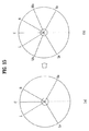
図12は、5.1チャンネルのマルチチャンネルオーディオ信号の位置と6.1チャンネルの出力チャンネルオーディオ信号の位置を示す図である。図12の(a)を参照すると、5.1チャンネルのマルチチャンネルオーディオ信号のチャンネル位置がそれぞれ、左側前方チャンネルL、右側前方チャンネルR、センターチャンネルC、低周波チャンネルLFE(図示せず)、左側サラウンドチャンネルLs、右側サラウンドチャンネルRsであることがわかる。もし、このような5.1チャンネルのマルチチャンネルオーディオ信号がダウンミックスされたオーディオ信号である場合、このダウンミックスオーディオ信号に空間パラメータのみを適用すると、再び5.1チャンネルのマルチチャンネルオーディオ信号にアップミックスされる。しかし、図12の(b)のように、6.1チャンネルのマルチチャンネルオーディオ信号にアップミックスするためには、後方センター(rear center)RCのチャンネル信号をさらに生成しなければならない。 FIG. 12 is a diagram showing the position of the 5.1 channel multi-channel audio signal and the position of the 6.1 channel output channel audio signal. Referring to FIG. 12A, the channel positions of the 5.1 channel multi-channel audio signal are the left front channel L, right front channel R, center channel C, low frequency channel LFE (not shown), left side, respectively. It can be seen that the surround channel Ls and the right surround channel Rs. If the 5.1 channel multi-channel audio signal is a downmixed audio signal, applying only the spatial parameter to the downmix audio signal will increase the 5.1 channel multichannel audio signal again. To be mixed. However, as shown in (b) of FIG. 12, in order to upmix a 6.1 channel multi-channel audio signal, a rear center RC channel signal must be further generated.
この後方センターRCのチャンネル信号は、後方の2チャンネル(左側サラウンドチャンネルLs及び右側サラウンドチャンネルRs)と関連した空間パラメータを用いて生成できる。具体的に、空間パラメータのうち、チャンネル間レベル差(CLD)は2チャンネル間のレベル差を表すが、2チャンネル間のレベル差を調整することによって、2チャンネル間に存在する仮想音源の位置を変化させることができる。 The channel signal of the rear center RC can be generated using spatial parameters associated with the two rear channels (the left surround channel Ls and the right surround channel Rs). Specifically, among the spatial parameters, the inter-channel level difference (CLD) represents the level difference between the two channels, and the position of the virtual sound source existing between the two channels can be determined by adjusting the level difference between the two channels. Can be changed.
以下では、2チャンネル間のレベル差によって仮想音源の位置が変化する原理について説明する。 Hereinafter, the principle of changing the position of the virtual sound source due to the level difference between the two channels will be described.
図13は、2チャンネル間のレベル差と仮想音源の位置との関係を示す図である。図13で、左側サラウンドチャンネルLsのレベルがaで、右側サラウンドチャンネルRsのレベルがbである。図13の(a)を参照すると、左側サラウンドチャンネルLsのレベルaが右側サラウンドチャンネルRsのレベルbよりも大きい場合、仮想音源の位置VSは、右側サラウンドチャンネルRsの位置よりも左側サラウンドチャンネルLsの位置に近いことがわかる。2チャンネルからオーディオ信号が出力される場合、聴き手は2チャンネル間に仮想音源が存在するかのように感じることになるが、この時、仮想音源の位置は、2チャンネルのうちレベルが相対的に高いチャンネルの位置に近い。図13の(b)の場合は、左側サラウンドチャンネルLsのレベルaが右側サラウンドチャンネルRsのレベルbと略同一なので、仮想音源の位置が左側サラウンドチャンネルLs及び右側サラウンドチャンネルRsの中間に存在するかのように聴き手は感じることになる。 FIG. 13 is a diagram showing the relationship between the level difference between two channels and the position of the virtual sound source. In FIG. 13, the level of the left surround channel Ls is a, and the level of the right surround channel Rs is b. Referring to FIG. 13A, when the level a of the left surround channel Ls is higher than the level b of the right surround channel Rs, the virtual sound source position VS is higher than that of the right surround channel Rs. You can see that it is close to the position. When audio signals are output from two channels, the listener feels as if a virtual sound source exists between the two channels. At this time, the position of the virtual sound source is relative to the level of the two channels. Close to high channel position. In the case of FIG. 13B, since the level a of the left surround channel Ls is substantially the same as the level b of the right surround channel Rs, does the virtual sound source position exist between the left surround channel Ls and the right surround channel Rs? The listener will feel like this.
このような原理を用いて後方センターRCのレベルの決定することができる。図14は、2つの後方チャンネルのレベル、及び後方センターチャンネルのレベルを示す図である。図14に示すように、後方センターチャンネルRCのレベルcは、左側サラウンドチャンネルLsのレベルa及び右側サラウンドチャンネルRsのレベルb間の差を内挿する方式で算出することができる。内挿方式としては、線形(linear)内挿だけでなく、非線形(non−linear)内挿方式も適用されることができる。線形内挿方式によって、2チャンネル(例:Ls,Rs)間に存在する新しいチャンネル(例:後方センターチャンネルRC)のレベルcを算出する式は、次の通りである。 Using such a principle, the level of the rear center RC can be determined. FIG. 14 is a diagram illustrating the levels of two rear channels and the level of the rear center channel. As shown in FIG. 14, the level c of the rear center channel RC can be calculated by interpolating the difference between the level a of the left surround channel Ls and the level b of the right surround channel Rs. As the interpolation method, not only linear interpolation but also non-linear interpolation method can be applied. An equation for calculating the level c of a new channel (eg, rear center channel RC) existing between two channels (eg, Ls, Rs) by the linear interpolation method is as follows.
[式42]
c=a*k+b*(1-k)
[Formula 42]
c = a * k + b * (1-k)
ここで、a、bは、2チャンネルのそれぞれのレベルを表す。 Here, a and b represent the levels of the two channels.
kは、aレベルのチャンネル及びbレベルのチャンネルとcレベルのチャンネル間の相対的位置を表す。 k represents a relative position between the a-level channel and the b-level channel and the c-level channel.
もし、cレベルのチャンネル(例:後方センターチャンネルRC)がaレベルのチャンネル(例:Ls)及びbレベルのチャンネルRsの真中央に位置する場合、kは0.5である。kが0.5の場合、式42は、次の式のようになる。 If the c level channel (eg, rear center channel RC) is located at the exact center of the a level channel (eg, Ls) and the b level channel Rs, k is 0.5. When k is 0.5, the equation 42 becomes the following equation.
[式43]
c=(a+b)/2
[Formula 43]
c = (a + b) / 2
式43によれば、cレベルのチャンネル(例:後方センターチャンネルRC)がaレベルのチャンネル(例:Ls)及びbレベルのチャンネルRsの真中央に位置する場合、新しいチャンネルのレベルcは、既存のチャンネルのレベルa,bの平均値となる。上の式42及び式43は一例に過ぎず、cレベルの決定だけでなく、aレベルとbレベルの値も再調整することが可能である。 According to Equation 43, if the c-level channel (eg, rear center channel RC) is located at the center of the a-level channel (eg, Ls) and the b-level channel Rs, the new channel level c The average value of the levels a and b of the channels. The above equations 42 and 43 are merely examples, and not only the determination of the c level but also the values of the a level and the b level can be readjusted.
(3)−2−2.7.1チャンネルへの拡張
マルチチャンネルオーディオ信号が5.1チャンネルである時、7.1チャンネルの出力チャンネルオーディオ信号を生成したい場合に挙げて説明する。
(3) -2-2.7.1 Extension to Channel This example will be described in the case where it is desired to generate a 7.1-channel output channel audio signal when the multi-channel audio signal is 5.1 channel.
図15は、5.1チャンネルのマルチチャンネルオーディオ信号の位置と7.1チャンネルの出力チャンネルオーディオ信号の位置を示す図である。図15の(a)を参照すると、図12の(a)と同様に、5.1チャンネルのマルチチャンネルオーディオ信号のチャンネル位置がそれぞれ左側前方チャンネルL、右側前方チャンネルR、センターチャンネルC、低周波チャンネルLFE(図示せず)、左側サラウンドチャンネルLs、右側サラウンドチャンネルRsであることがわかる。もし、このような5.1チャンネルのマルチチャンネルオーディオ信号がダウンミックスされたオーディオ信号である場合、このダウンミックスオーディオ信号に空間パラメータのみを適用すると、同様に5.1チャンネルのマルチチャンネルオーディオ信号にアップミックスされる。しかし、図15の(b)のように7.1チャンネルのマルチチャンネルオーディオ信号にアップミックスするには、左側フロントサイドチャンネルLfs及び右側フロントサイドチャンネルRfsをさらに生成しなければならない。 FIG. 15 is a diagram showing the position of the 5.1 channel multi-channel audio signal and the position of the 7.1 channel output channel audio signal. Referring to (a) of FIG. 15, the channel positions of the 5.1 channel multi-channel audio signal are the left front channel L, the right front channel R, the center channel C, the low frequency, respectively, as in FIG. 12 (a). It can be seen that the channel LFE (not shown), the left surround channel Ls, and the right surround channel Rs. If such a 5.1 channel multi-channel audio signal is a downmixed audio signal, applying only a spatial parameter to the downmix audio signal will similarly result in a 5.1 channel multichannel audio signal. Upmixed. However, in order to upmix the 7.1-channel multi-channel audio signal as shown in FIG. 15B, the left front side channel Lfs and the right front side channel Rfs must be further generated.
左側フロントサイドチャンネルLfsは、左側前方チャンネルL及び左側サラウンドチャンネルLs間に位置するので、左側前方チャンネルLのレベル及び左側サラウンドチャンネルLsのレベルを用いて、内挿方式で左側フロントサイドチャンネルLfsのレベルを決定することができる。図16は、2つの左側チャンネルのレベル、及び左側フロントサイドチャンネルLfsのレベルを示す図である。図16を参照すると、左側フロントサイドチャンネルLfsのレベルcは、左側前方チャンネルLのレベルa及び左側サラウンドチャンネルLsのレベルbに基づいて線形的に内挿された値であることがわかる。 Since the left front side channel Lfs is located between the left front channel L and the left surround channel Ls, the level of the left front side channel Lfs is interpolated using the level of the left front channel L and the level of the left surround channel Ls. Can be determined. FIG. 16 is a diagram illustrating the levels of the two left channels and the level of the left front side channel Lfs. Referring to FIG. 16, it can be seen that the level c of the left front side channel Lfs is a value interpolated linearly based on the level a of the left front channel L and the level b of the left surround channel Ls.
一方、左側フロントサイドチャンネルLfsは、左側前方チャンネルL及び左側サラウンドチャンネルLs間に位置してはいるが、左側前方チャンネルL、センターチャンネルC、及び右側前方チャンネルRの外側に位置してもいる。このため、左側前方チャンネルLのレベル、センターチャンネルCのレベル、及び右側前方チャンネルRのレベルを用いて、外挿方式で左側フロントサイドチャンネルLfsのレベルを決定しても良い。図17は、3つの前方チャンネルのレベル、及び左側フロントサイドチャンネルのレベルを示す図である。図17を参照すると、左側フロントサイドチャンネルLfsのレベルdは、左側前方チャンネルLのレベルa、センターチャンネルCのレベルc、及び右側前方チャンネルRのレベルbに基づいて線形的に外挿された値であることがわかる。 On the other hand, the left front side channel Lfs is located between the left front channel L and the left surround channel Ls, but is located outside the left front channel L, the center channel C, and the right front channel R. Therefore, the level of the left front side channel Lfs may be determined by extrapolation using the level of the left front channel L, the level of the center channel C, and the level of the right front channel R. FIG. 17 is a diagram illustrating the levels of the three front channels and the level of the left front side channel. Referring to FIG. 17, the level d of the left front side channel Lfs is a value extrapolated linearly based on the level a of the left front channel L, the level c of the center channel C, and the level b of the right front channel R. It can be seen that it is.
以上2つの場合を取り上げて、空間情報に拡張空間情報を追加して出力チャンネルオーディオ信号を生成する過程について説明した。上述の如く、拡張空間情報を追加してアップミキシングする過程において、拡張空間パラメータの全部ではなく一部のみを適用しても良い。このようにオーディオ信号に空間パラメータを適用する過程は、順次的・階層的に行われても良いが、一括的・統合的に処理されても良い。 In the above two cases, the process of generating the output channel audio signal by adding the extended spatial information to the spatial information has been described. As described above, in the process of adding and mixing the extended space information, only a part of the extended space parameters may be applied instead of the whole. Thus, the process of applying the spatial parameter to the audio signal may be performed sequentially or hierarchically, but may be processed collectively or collectively.
本発明の一側面によれば、定められたツリー構造と異なる構造のオーディオ信号を生成できるため、多様な構造のオーディオ信号を生成することが可能になる。 According to one aspect of the present invention, an audio signal having a structure different from a predetermined tree structure can be generated, and therefore, an audio signal having various structures can be generated.
本発明の他の側面によれば、定められたツリー構造と異なる構造のオーディオ信号を生成できるため、ダウンミックスされる前のマルチチャンネルの本数がスピーカーの個数より多いまたは少ない場合であっても、ダウンミックスオーディオ信号からスピーカーの個数と同じ本数の出力チャンネルを生成することが可能になる。 According to another aspect of the present invention, since an audio signal having a structure different from a predetermined tree structure can be generated, even when the number of multi-channels before being downmixed is larger or smaller than the number of speakers, It is possible to generate the same number of output channels as the number of speakers from the downmix audio signal.
本発明のさらに他の側面によれば、マルチチャンネル数より少ない本数の出力チャンネルを生成する場合、ダウンミックスオーディオ信号からマルチチャンネルオーディオ信号にアップミックスした後、このマルチチャンネルオーディオ信号から出力チャンネルオーディオ信号をダウンミックスするのではなく、ダウンミックスオーディオ信号から直接マルチチャンネルオーディオ信号を生成するので、オーディオ信号のデコーディングにかかる演算量を顕著に減少させることが可能になる。 According to still another aspect of the present invention, when generating fewer output channels than the number of multi-channels, an up-channel audio signal is output from the multi-channel audio signal after up-mixing from the down-mix audio signal to the multi-channel audio signal. Since the multi-channel audio signal is generated directly from the downmix audio signal rather than downmixing, it is possible to remarkably reduce the amount of calculation required for decoding the audio signal.
本発明のさらに他の側面によれば、組合せ空間情報の生成において音響経路を考慮できるため、サラウンドチャンネルを出力できない状況においても仮想(pseudo)でサラウンド効果を出すことが可能になる。 According to still another aspect of the present invention, since the acoustic path can be considered in generating the combination space information, a surround effect can be obtained virtually even in a situation where a surround channel cannot be output.
Claims (11)
変形空間情報のタイプを識別する段階と、
前記空間情報を用いて前記変形空間情報を生成する段階と、
前記変形空間情報を用いて前記オーディオ信号をデコーディングする段階と、
を含み、
前記変形空間情報のタイプは、部分空間情報、組合せ空間情報、及び拡大空間情報のうち一つ以上を含むことを特徴とする、オーディオ信号のデコーディング方法。 Receiving an audio signal and spatial information;
Identifying the type of deformation space information;
Generating the deformation space information using the space information;
Decoding the audio signal using the transformed spatial information;
Including
The method of decoding an audio signal, wherein the type of modified spatial information includes at least one of partial spatial information, combined spatial information, and expanded spatial information.
前記部分空間情報は前記空間パラメータのうちの一部を含むことを特徴とする、請求項1に記載のオーディオ信号のデコーディング方法。 The spatial information includes spatial parameters;
The method of claim 1, wherein the partial space information includes a part of the spatial parameters.
前記部分空間情報は上位階層の空間パラメータを含むことを特徴とする、請求項5に記載のオーディオ信号のデコーディング方法。 The spatial parameters are hierarchical;
6. The audio signal decoding method according to claim 5, wherein the subspace information includes an upper layer spatial parameter.
前記組合せ空間情報は前記空間パラメータを組み合わせて生成したことを特徴とする、請求項1に記載のオーディオ信号のデコーディング方法。 The spatial information includes spatial parameters;
2. The audio signal decoding method according to claim 1, wherein the combination space information is generated by combining the space parameters.
前記拡張空間情報は拡張空間パラメータを含み、
前記拡張空間パラメータは前記空間パラメータを用いて計算したものであることを特徴とする、請求項9に記載のオーディオ信号のデコーディング方法。 The spatial information includes spatial parameters;
The extended spatial information includes extended spatial parameters;
10. The audio signal decoding method according to claim 9, wherein the extended spatial parameter is calculated using the spatial parameter.
前記変形空間情報を用いてオーディオ信号をデコーディングする出力チャンネル生成部と、を備え、
前記変形空間情報のタイプは、部分空間情報、組合せ空間情報、及び拡大空間情報のうち一つ以上を含むことを特徴とする、オーディオ信号のデコーディング装置。 A deformation space information generation unit that identifies a type of deformation space information using the space information and generates the deformation space information using the space information;
An output channel generator for decoding an audio signal using the modified spatial information,
The audio signal decoding apparatus according to claim 1, wherein the type of the modified spatial information includes at least one of partial spatial information, combined spatial information, and expanded spatial information.
Applications Claiming Priority (9)
| Application Number | Priority Date | Filing Date | Title |
|---|---|---|---|
| US71652405P | 2005-09-14 | 2005-09-14 | |
| US75998006P | 2006-01-19 | 2006-01-19 | |
| US76036006P | 2006-01-20 | 2006-01-20 | |
| US77366906P | 2006-02-16 | 2006-02-16 | |
| US77672406P | 2006-02-27 | 2006-02-27 | |
| US78751606P | 2006-03-31 | 2006-03-31 | |
| US81602206P | 2006-06-22 | 2006-06-22 | |
| KR20060078300 | 2006-08-18 | ||
| PCT/KR2006/003666 WO2007032650A1 (en) | 2005-09-14 | 2006-09-14 | Method and apparatus for decoding an audio signal |
Publications (1)
| Publication Number | Publication Date |
|---|---|
| JP2009508176A true JP2009508176A (en) | 2009-02-26 |
Family
ID=37865187
Family Applications (2)
| Application Number | Title | Priority Date | Filing Date |
|---|---|---|---|
| JP2008531018A Pending JP2009508176A (en) | 2005-09-14 | 2006-09-14 | Audio signal decoding method and apparatus |
| JP2008531017A Active JP5108772B2 (en) | 2005-09-14 | 2006-09-14 | Audio signal decoding method and apparatus |
Family Applications After (1)
| Application Number | Title | Priority Date | Filing Date |
|---|---|---|---|
| JP2008531017A Active JP5108772B2 (en) | 2005-09-14 | 2006-09-14 | Audio signal decoding method and apparatus |
Country Status (8)
| Country | Link |
|---|---|
| US (6) | US20080255857A1 (en) |
| EP (4) | EP1946297B1 (en) |
| JP (2) | JP2009508176A (en) |
| KR (4) | KR100857107B1 (en) |
| AU (1) | AU2006291689B2 (en) |
| CA (1) | CA2621664C (en) |
| HK (1) | HK1126306A1 (en) |
| WO (4) | WO2007032647A1 (en) |
Cited By (1)
| Publication number | Priority date | Publication date | Assignee | Title |
|---|---|---|---|---|
| JP2009508175A (en) * | 2005-09-14 | 2009-02-26 | エルジー エレクトロニクス インコーポレイティド | Audio signal decoding method and apparatus |
Families Citing this family (18)
| Publication number | Priority date | Publication date | Assignee | Title |
|---|---|---|---|---|
| KR100888474B1 (en) * | 2005-11-21 | 2009-03-12 | 삼성전자주식회사 | Apparatus and method for encoding/decoding multichannel audio signal |
| US7965848B2 (en) * | 2006-03-29 | 2011-06-21 | Dolby International Ab | Reduced number of channels decoding |
| CN103400583B (en) * | 2006-10-16 | 2016-01-20 | 杜比国际公司 | Enhancing coding and the Parametric Representation of object coding is mixed under multichannel |
| AU2007312597B2 (en) * | 2006-10-16 | 2011-04-14 | Dolby International Ab | Apparatus and method for multi -channel parameter transformation |
| CN101960514A (en) | 2008-03-14 | 2011-01-26 | 日本电气株式会社 | Signal analysis/control system and method, signal control device and method, and program |
| EP2214161A1 (en) * | 2009-01-28 | 2010-08-04 | Fraunhofer-Gesellschaft zur Förderung der angewandten Forschung e.V. | Apparatus, method and computer program for upmixing a downmix audio signal |
| KR101283783B1 (en) * | 2009-06-23 | 2013-07-08 | 한국전자통신연구원 | Apparatus for high quality multichannel audio coding and decoding |
| JP4917189B2 (en) | 2009-09-01 | 2012-04-18 | パナソニック株式会社 | Digital broadcast transmission apparatus, digital broadcast reception apparatus, and digital broadcast transmission / reception system |
| CN102792378B (en) | 2010-01-06 | 2015-04-29 | Lg电子株式会社 | An apparatus for processing an audio signal and method thereof |
| US8913757B2 (en) * | 2010-02-05 | 2014-12-16 | Qnx Software Systems Limited | Enhanced spatialization system with satellite device |
| JP5243620B2 (en) | 2010-06-09 | 2013-07-24 | パナソニック株式会社 | Band extension method, band extension apparatus, program, integrated circuit, and audio decoding apparatus |
| US9154878B2 (en) * | 2012-01-10 | 2015-10-06 | Monster, Llc | Interconnected speaker system |
| CN104054126B (en) * | 2012-01-19 | 2017-03-29 | 皇家飞利浦有限公司 | Space audio is rendered and is encoded |
| US9774974B2 (en) * | 2014-09-24 | 2017-09-26 | Electronics And Telecommunications Research Institute | Audio metadata providing apparatus and method, and multichannel audio data playback apparatus and method to support dynamic format conversion |
| GB201718341D0 (en) * | 2017-11-06 | 2017-12-20 | Nokia Technologies Oy | Determination of targeted spatial audio parameters and associated spatial audio playback |
| GB2572650A (en) | 2018-04-06 | 2019-10-09 | Nokia Technologies Oy | Spatial audio parameters and associated spatial audio playback |
| GB2574239A (en) | 2018-05-31 | 2019-12-04 | Nokia Technologies Oy | Signalling of spatial audio parameters |
| JP2023515886A (en) * | 2020-03-02 | 2023-04-14 | マジック リープ, インコーポレイテッド | Immersive audio platform |
Citations (6)
| Publication number | Priority date | Publication date | Assignee | Title |
|---|---|---|---|---|
| WO2004008805A1 (en) * | 2002-07-12 | 2004-01-22 | Koninklijke Philips Electronics N.V. | Audio coding |
| WO2005081229A1 (en) * | 2004-02-25 | 2005-09-01 | Matsushita Electric Industrial Co., Ltd. | Audio encoder and audio decoder |
| JP2006166447A (en) * | 2004-12-01 | 2006-06-22 | Samsung Electronics Co Ltd | Apparatus and method for processing multi-channel audio signal, compression efficiency improving method and system for processing multi-channel audio signal |
| JP2009508175A (en) * | 2005-09-14 | 2009-02-26 | エルジー エレクトロニクス インコーポレイティド | Audio signal decoding method and apparatus |
| JP2009508157A (en) * | 2005-09-13 | 2009-02-26 | コーニンクレッカ フィリップス エレクトロニクス エヌ ヴィ | Audio encoding |
| JP2009508432A (en) * | 2005-09-14 | 2009-02-26 | エルジー エレクトロニクス インコーポレイティド | Audio signal decoding method and apparatus |
Family Cites Families (75)
| Publication number | Priority date | Publication date | Assignee | Title |
|---|---|---|---|---|
| US5166685A (en) * | 1990-09-04 | 1992-11-24 | Motorola, Inc. | Automatic selection of external multiplexer channels by an A/D converter integrated circuit |
| US5632005A (en) * | 1991-01-08 | 1997-05-20 | Ray Milton Dolby | Encoder/decoder for multidimensional sound fields |
| DE4217276C1 (en) | 1992-05-25 | 1993-04-08 | Fraunhofer-Gesellschaft Zur Foerderung Der Angewandten Forschung Ev, 8000 Muenchen, De | |
| DE4236989C2 (en) | 1992-11-02 | 1994-11-17 | Fraunhofer Ges Forschung | Method for transmitting and / or storing digital signals of multiple channels |
| JP2924539B2 (en) | 1993-01-29 | 1999-07-26 | 日本ビクター株式会社 | Sound image localization control method |
| ES2165370T3 (en) | 1993-06-22 | 2002-03-16 | Thomson Brandt Gmbh | METHOD FOR OBTAINING A MULTICHANNEL DECODING MATRIX. |
| EP0637191B1 (en) * | 1993-07-30 | 2003-10-22 | Victor Company Of Japan, Ltd. | Surround signal processing apparatus |
| DE69523643T2 (en) * | 1994-02-25 | 2002-05-16 | Henrik Moller | Binaural synthesis, head-related transfer function, and their use |
| JP3397001B2 (en) | 1994-06-13 | 2003-04-14 | ソニー株式会社 | Encoding method and apparatus, decoding apparatus, and recording medium |
| US5703584A (en) * | 1994-08-22 | 1997-12-30 | Adaptec, Inc. | Analog data acquisition system |
| JPH08123494A (en) | 1994-10-28 | 1996-05-17 | Mitsubishi Electric Corp | Speech encoding device, speech decoding device, speech encoding and decoding method, and phase amplitude characteristic derivation device usable for same |
| JPH08202397A (en) | 1995-01-30 | 1996-08-09 | Olympus Optical Co Ltd | Voice decoding device |
| JP3088319B2 (en) * | 1996-02-07 | 2000-09-18 | 松下電器産業株式会社 | Decoding device and decoding method |
| US5912636A (en) * | 1996-09-26 | 1999-06-15 | Ricoh Company, Ltd. | Apparatus and method for performing m-ary finite state machine entropy coding |
| KR100206333B1 (en) | 1996-10-08 | 1999-07-01 | 윤종용 | Device and method for the reproduction of multichannel audio using two speakers |
| US6711266B1 (en) * | 1997-02-07 | 2004-03-23 | Bose Corporation | Surround sound channel encoding and decoding |
| JP3572165B2 (en) | 1997-04-04 | 2004-09-29 | 株式会社デノン | Video / audio signal reproducing apparatus and video / audio signal reproducing method |
| US6307941B1 (en) * | 1997-07-15 | 2001-10-23 | Desper Products, Inc. | System and method for localization of virtual sound |
| AU751900B2 (en) | 1998-03-25 | 2002-08-29 | Lake Technology Limited | Audio signal processing method and apparatus |
| US6574339B1 (en) * | 1998-10-20 | 2003-06-03 | Samsung Electronics Co., Ltd. | Three-dimensional sound reproducing apparatus for multiple listeners and method thereof |
| JP3346556B2 (en) * | 1998-11-16 | 2002-11-18 | 日本ビクター株式会社 | Audio encoding method and audio decoding method |
| EP1054575A3 (en) | 1999-05-17 | 2002-09-18 | Bose Corporation | Directional decoding |
| KR100416757B1 (en) | 1999-06-10 | 2004-01-31 | 삼성전자주식회사 | Multi-channel audio reproduction apparatus and method for loud-speaker reproduction |
| KR20010009258A (en) | 1999-07-08 | 2001-02-05 | 허진호 | Virtual multi-channel recoding system |
| US6611293B2 (en) * | 1999-12-23 | 2003-08-26 | Dfr2000, Inc. | Method and apparatus for synchronization of ancillary information in film conversion |
| US6973130B1 (en) * | 2000-04-25 | 2005-12-06 | Wee Susie J | Compressed video signal including information for independently coded regions |
| US7212872B1 (en) | 2000-05-10 | 2007-05-01 | Dts, Inc. | Discrete multichannel audio with a backward compatible mix |
| JP4304401B2 (en) | 2000-06-07 | 2009-07-29 | ソニー株式会社 | Multi-channel audio playback device |
| WO2004019656A2 (en) | 2001-02-07 | 2004-03-04 | Dolby Laboratories Licensing Corporation | Audio channel spatial translation |
| JP3566220B2 (en) | 2001-03-09 | 2004-09-15 | 三菱電機株式会社 | Speech coding apparatus, speech coding method, speech decoding apparatus, and speech decoding method |
| US7292901B2 (en) * | 2002-06-24 | 2007-11-06 | Agere Systems Inc. | Hybrid multi-channel/cue coding/decoding of audio signals |
| US7583805B2 (en) * | 2004-02-12 | 2009-09-01 | Agere Systems Inc. | Late reverberation-based synthesis of auditory scenes |
| SE0202159D0 (en) | 2001-07-10 | 2002-07-09 | Coding Technologies Sweden Ab | Efficientand scalable parametric stereo coding for low bitrate applications |
| KR100480787B1 (en) * | 2001-11-27 | 2005-04-07 | 삼성전자주식회사 | Encoding/decoding method and apparatus for key value of coordinate interpolator node |
| AUPR955001A0 (en) * | 2001-12-11 | 2002-01-24 | Medivac Technology Pty Limited | Compact waste treatment apparatus |
| DE60323331D1 (en) | 2002-01-30 | 2008-10-16 | Matsushita Electric Ind Co Ltd | METHOD AND DEVICE FOR AUDIO ENCODING AND DECODING |
| EP1341160A1 (en) | 2002-03-01 | 2003-09-03 | Deutsche Thomson-Brandt Gmbh | Method and apparatus for encoding and for decoding a digital information signal |
| US8340302B2 (en) | 2002-04-22 | 2012-12-25 | Koninklijke Philips Electronics N.V. | Parametric representation of spatial audio |
| US7391869B2 (en) | 2002-05-03 | 2008-06-24 | Harman International Industries, Incorporated | Base management systems |
| JP4296752B2 (en) * | 2002-05-07 | 2009-07-15 | ソニー株式会社 | Encoding method and apparatus, decoding method and apparatus, and program |
| US6703584B2 (en) * | 2002-05-13 | 2004-03-09 | Seagate Technology Llc | Disc clamp adjustment using heat |
| JP3579047B2 (en) | 2002-07-19 | 2004-10-20 | 日本電気株式会社 | Audio decoding device, decoding method, and program |
| CN1219414C (en) | 2002-07-23 | 2005-09-14 | 华南理工大学 | Two-loudspeaker virtual 5.1 path surround sound signal processing method |
| CN1973318B (en) | 2002-10-14 | 2012-01-25 | 汤姆森许可贸易公司 | Method and device for coding and decoding the presentation of an audio signal |
| WO2004036549A1 (en) | 2002-10-14 | 2004-04-29 | Koninklijke Philips Electronics N.V. | Signal filtering |
| AU2003269551A1 (en) | 2002-10-15 | 2004-05-04 | Electronics And Telecommunications Research Institute | Method for generating and consuming 3d audio scene with extended spatiality of sound source |
| EP1552723A4 (en) | 2002-10-15 | 2010-02-17 | Korea Electronics Telecomm | Apparatus and method for adapting audio signal according to user's preference |
| ES2273216T3 (en) | 2003-02-11 | 2007-05-01 | Koninklijke Philips Electronics N.V. | AUDIO CODING |
| KR100917464B1 (en) | 2003-03-07 | 2009-09-14 | 삼성전자주식회사 | Method and apparatus for encoding/decoding digital data using bandwidth extension technology |
| US8054980B2 (en) * | 2003-09-05 | 2011-11-08 | Stmicroelectronics Asia Pacific Pte, Ltd. | Apparatus and method for rendering audio information to virtualize speakers in an audio system |
| US7447317B2 (en) | 2003-10-02 | 2008-11-04 | Fraunhofer-Gesellschaft Zur Foerderung Der Angewandten Forschung E.V | Compatible multi-channel coding/decoding by weighting the downmix channel |
| KR20050060789A (en) * | 2003-12-17 | 2005-06-22 | 삼성전자주식회사 | Apparatus and method for controlling virtual sound |
| US7394903B2 (en) | 2004-01-20 | 2008-07-01 | Fraunhofer-Gesellschaft Zur Forderung Der Angewandten Forschung E.V. | Apparatus and method for constructing a multi-channel output signal or for generating a downmix signal |
| US7805313B2 (en) * | 2004-03-04 | 2010-09-28 | Agere Systems Inc. | Frequency-based coding of channels in parametric multi-channel coding systems |
| KR100773539B1 (en) * | 2004-07-14 | 2007-11-05 | 삼성전자주식회사 | Multi channel audio data encoding/decoding method and apparatus |
| TWI393121B (en) | 2004-08-25 | 2013-04-11 | Dolby Lab Licensing Corp | Method and apparatus for processing a set of n audio signals, and computer program associated therewith |
| US8204261B2 (en) * | 2004-10-20 | 2012-06-19 | Fraunhofer-Gesellschaft Zur Foerderung Der Angewandten Forschung E.V. | Diffuse sound shaping for BCC schemes and the like |
| SE0402650D0 (en) * | 2004-11-02 | 2004-11-02 | Coding Tech Ab | Improved parametric stereo compatible coding or spatial audio |
| US7787631B2 (en) * | 2004-11-30 | 2010-08-31 | Agere Systems Inc. | Parametric coding of spatial audio with cues based on transmitted channels |
| US7903824B2 (en) * | 2005-01-10 | 2011-03-08 | Agere Systems Inc. | Compact side information for parametric coding of spatial audio |
| US7961890B2 (en) * | 2005-04-15 | 2011-06-14 | Fraunhofer-Gesellschaft Zur Foerderung Der Angewandten Forschung, E.V. | Multi-channel hierarchical audio coding with compact side information |
| US7751572B2 (en) * | 2005-04-15 | 2010-07-06 | Dolby International Ab | Adaptive residual audio coding |
| AU2006255662B2 (en) * | 2005-06-03 | 2012-08-23 | Dolby Laboratories Licensing Corporation | Apparatus and method for encoding audio signals with decoding instructions |
| US20070055510A1 (en) * | 2005-07-19 | 2007-03-08 | Johannes Hilpert | Concept for bridging the gap between parametric multi-channel audio coding and matrixed-surround multi-channel coding |
| RU2380767C2 (en) | 2005-09-14 | 2010-01-27 | ЭлДжи ЭЛЕКТРОНИКС ИНК. | Method and device for audio signal decoding |
| KR100888474B1 (en) * | 2005-11-21 | 2009-03-12 | 삼성전자주식회사 | Apparatus and method for encoding/decoding multichannel audio signal |
| JP2007143596A (en) | 2005-11-24 | 2007-06-14 | Tekken Constr Co Ltd | Mounting frame of game machine or the like |
| US20070121953A1 (en) * | 2005-11-28 | 2007-05-31 | Mediatek Inc. | Audio decoding system and method |
| KR100803212B1 (en) * | 2006-01-11 | 2008-02-14 | 삼성전자주식회사 | Method and apparatus for scalable channel decoding |
| KR101294022B1 (en) * | 2006-02-03 | 2013-08-08 | 한국전자통신연구원 | Method and apparatus for control of randering multiobject or multichannel audio signal using spatial cue |
| KR100773562B1 (en) * | 2006-03-06 | 2007-11-07 | 삼성전자주식회사 | Method and apparatus for generating stereo signal |
| CN101411214B (en) * | 2006-03-28 | 2011-08-10 | 艾利森电话股份有限公司 | Method and arrangement for a decoder for multi-channel surround sound |
| US8266195B2 (en) * | 2006-03-28 | 2012-09-11 | Telefonaktiebolaget L M Ericsson (Publ) | Filter adaptive frequency resolution |
| US7965848B2 (en) * | 2006-03-29 | 2011-06-21 | Dolby International Ab | Reduced number of channels decoding |
| US8027479B2 (en) * | 2006-06-02 | 2011-09-27 | Coding Technologies Ab | Binaural multi-channel decoder in the context of non-energy conserving upmix rules |
-
2006
- 2006-09-14 KR KR1020087005388A patent/KR100857107B1/en active IP Right Grant
- 2006-09-14 EP EP06798775.0A patent/EP1946297B1/en active Active
- 2006-09-14 JP JP2008531018A patent/JP2009508176A/en active Pending
- 2006-09-14 US US12/066,645 patent/US20080255857A1/en not_active Abandoned
- 2006-09-14 EP EP06783786.4A patent/EP1946295B1/en not_active Not-in-force
- 2006-09-14 US US12/066,651 patent/US20080228501A1/en not_active Abandoned
- 2006-09-14 CA CA2621664A patent/CA2621664C/en active Active
- 2006-09-14 EP EP06798774A patent/EP1946296A4/en not_active Withdrawn
- 2006-09-14 KR KR1020087005384A patent/KR100857105B1/en active IP Right Grant
- 2006-09-14 WO PCT/KR2006/003661 patent/WO2007032647A1/en active Application Filing
- 2006-09-14 WO PCT/KR2006/003659 patent/WO2007032646A1/en active Application Filing
- 2006-09-14 KR KR1020087005389A patent/KR100857108B1/en active IP Right Grant
- 2006-09-14 AU AU2006291689A patent/AU2006291689B2/en active Active
- 2006-09-14 JP JP2008531017A patent/JP5108772B2/en active Active
- 2006-09-14 WO PCT/KR2006/003662 patent/WO2007032648A1/en active Application Filing
- 2006-09-14 WO PCT/KR2006/003666 patent/WO2007032650A1/en active Application Filing
- 2006-09-14 EP EP06798772A patent/EP1938312A4/en not_active Ceased
- 2006-09-14 KR KR1020087005385A patent/KR100857106B1/en active IP Right Grant
-
2009
- 2009-05-21 HK HK09104644.3A patent/HK1126306A1/en unknown
-
2011
- 2011-01-24 US US13/012,641 patent/US20110182431A1/en not_active Abandoned
- 2011-02-01 US US13/019,153 patent/US20110178808A1/en not_active Abandoned
- 2011-04-18 US US13/088,947 patent/US20110196687A1/en not_active Abandoned
- 2011-05-10 US US13/104,479 patent/US9747905B2/en active Active
Patent Citations (7)
| Publication number | Priority date | Publication date | Assignee | Title |
|---|---|---|---|---|
| WO2004008805A1 (en) * | 2002-07-12 | 2004-01-22 | Koninklijke Philips Electronics N.V. | Audio coding |
| WO2005081229A1 (en) * | 2004-02-25 | 2005-09-01 | Matsushita Electric Industrial Co., Ltd. | Audio encoder and audio decoder |
| JP2006166447A (en) * | 2004-12-01 | 2006-06-22 | Samsung Electronics Co Ltd | Apparatus and method for processing multi-channel audio signal, compression efficiency improving method and system for processing multi-channel audio signal |
| JP2009508157A (en) * | 2005-09-13 | 2009-02-26 | コーニンクレッカ フィリップス エレクトロニクス エヌ ヴィ | Audio encoding |
| JP2009508175A (en) * | 2005-09-14 | 2009-02-26 | エルジー エレクトロニクス インコーポレイティド | Audio signal decoding method and apparatus |
| JP2009508432A (en) * | 2005-09-14 | 2009-02-26 | エルジー エレクトロニクス インコーポレイティド | Audio signal decoding method and apparatus |
| JP2009508433A (en) * | 2005-09-14 | 2009-02-26 | エルジー エレクトロニクス インコーポレイティド | Audio signal decoding method and apparatus |
Non-Patent Citations (1)
| Title |
|---|
| JPN6011027358; Christof Faller, Frank Baumgarte: 'EFFICIENT REPRESENTATION OF SPATIAL AUDIO USING PERCEPTUAL PARAMETRIZATION' Proceedings of the 2001 IEEE Workshop on the Applications of Signal Processing to Audio and Acoustic , 20011021, p.199-202 * |
Cited By (2)
| Publication number | Priority date | Publication date | Assignee | Title |
|---|---|---|---|---|
| JP2009508175A (en) * | 2005-09-14 | 2009-02-26 | エルジー エレクトロニクス インコーポレイティド | Audio signal decoding method and apparatus |
| US9747905B2 (en) | 2005-09-14 | 2017-08-29 | Lg Electronics Inc. | Method and apparatus for decoding an audio signal |
Also Published As
Similar Documents
| Publication | Publication Date | Title |
|---|---|---|
| JP5108772B2 (en) | Audio signal decoding method and apparatus | |
| JP4728398B2 (en) | Audio signal decoding method and apparatus | |
| JP5450085B2 (en) | Audio processing method and apparatus | |
| RU2509442C2 (en) | Method and apparatus for applying reveberation to multichannel audio signal using spatial label parameters | |
| US20080235006A1 (en) | Method and Apparatus for Decoding an Audio Signal | |
| US20080221907A1 (en) | Method and Apparatus for Decoding an Audio Signal | |
| JP4988718B2 (en) | Audio signal decoding method and apparatus | |
| RU2380767C2 (en) | Method and device for audio signal decoding |
Legal Events
| Date | Code | Title | Description |
|---|---|---|---|
| A131 | Notification of reasons for refusal |
Free format text: JAPANESE INTERMEDIATE CODE: A131 Effective date: 20110531 |
|
| A521 | Written amendment |
Free format text: JAPANESE INTERMEDIATE CODE: A523 Effective date: 20110727 |
|
| A131 | Notification of reasons for refusal |
Free format text: JAPANESE INTERMEDIATE CODE: A131 Effective date: 20120424 |
|
| A521 | Written amendment |
Free format text: JAPANESE INTERMEDIATE CODE: A523 Effective date: 20120724 |
|
| A131 | Notification of reasons for refusal |
Free format text: JAPANESE INTERMEDIATE CODE: A131 Effective date: 20120911 |
|
| A02 | Decision of refusal |
Free format text: JAPANESE INTERMEDIATE CODE: A02 Effective date: 20130226 |