JP2009507221A - Cartridge with variable volume reservoir - Google Patents
Cartridge with variable volume reservoir Download PDFInfo
- Publication number
- JP2009507221A JP2009507221A JP2008529045A JP2008529045A JP2009507221A JP 2009507221 A JP2009507221 A JP 2009507221A JP 2008529045 A JP2008529045 A JP 2008529045A JP 2008529045 A JP2008529045 A JP 2008529045A JP 2009507221 A JP2009507221 A JP 2009507221A
- Authority
- JP
- Japan
- Prior art keywords
- cartridge
- channel
- variable volume
- solution
- reservoir
- Prior art date
- Legal status (The legal status is an assumption and is not a legal conclusion. Google has not performed a legal analysis and makes no representation as to the accuracy of the status listed.)
- Pending
Links
Images


Classifications
-
- B—PERFORMING OPERATIONS; TRANSPORTING
- B01—PHYSICAL OR CHEMICAL PROCESSES OR APPARATUS IN GENERAL
- B01L—CHEMICAL OR PHYSICAL LABORATORY APPARATUS FOR GENERAL USE
- B01L3/00—Containers or dishes for laboratory use, e.g. laboratory glassware; Droppers
- B01L3/50—Containers for the purpose of retaining a material to be analysed, e.g. test tubes
- B01L3/502—Containers for the purpose of retaining a material to be analysed, e.g. test tubes with fluid transport, e.g. in multi-compartment structures
- B01L3/5027—Containers for the purpose of retaining a material to be analysed, e.g. test tubes with fluid transport, e.g. in multi-compartment structures by integrated microfluidic structures, i.e. dimensions of channels and chambers are such that surface tension forces are important, e.g. lab-on-a-chip
- B01L3/502738—Containers for the purpose of retaining a material to be analysed, e.g. test tubes with fluid transport, e.g. in multi-compartment structures by integrated microfluidic structures, i.e. dimensions of channels and chambers are such that surface tension forces are important, e.g. lab-on-a-chip characterised by integrated valves
-
- B—PERFORMING OPERATIONS; TRANSPORTING
- B01—PHYSICAL OR CHEMICAL PROCESSES OR APPARATUS IN GENERAL
- B01F—MIXING, e.g. DISSOLVING, EMULSIFYING OR DISPERSING
- B01F31/00—Mixers with shaking, oscillating, or vibrating mechanisms
- B01F31/65—Mixers with shaking, oscillating, or vibrating mechanisms the materials to be mixed being directly submitted to a pulsating movement, e.g. by means of an oscillating piston or air column
-
- B—PERFORMING OPERATIONS; TRANSPORTING
- B01—PHYSICAL OR CHEMICAL PROCESSES OR APPARATUS IN GENERAL
- B01F—MIXING, e.g. DISSOLVING, EMULSIFYING OR DISPERSING
- B01F33/00—Other mixers; Mixing plants; Combinations of mixers
- B01F33/30—Micromixers
-
- B—PERFORMING OPERATIONS; TRANSPORTING
- B01—PHYSICAL OR CHEMICAL PROCESSES OR APPARATUS IN GENERAL
- B01L—CHEMICAL OR PHYSICAL LABORATORY APPARATUS FOR GENERAL USE
- B01L3/00—Containers or dishes for laboratory use, e.g. laboratory glassware; Droppers
- B01L3/50—Containers for the purpose of retaining a material to be analysed, e.g. test tubes
- B01L3/502—Containers for the purpose of retaining a material to be analysed, e.g. test tubes with fluid transport, e.g. in multi-compartment structures
- B01L3/5027—Containers for the purpose of retaining a material to be analysed, e.g. test tubes with fluid transport, e.g. in multi-compartment structures by integrated microfluidic structures, i.e. dimensions of channels and chambers are such that surface tension forces are important, e.g. lab-on-a-chip
- B01L3/502723—Containers for the purpose of retaining a material to be analysed, e.g. test tubes with fluid transport, e.g. in multi-compartment structures by integrated microfluidic structures, i.e. dimensions of channels and chambers are such that surface tension forces are important, e.g. lab-on-a-chip characterised by venting arrangements
-
- B—PERFORMING OPERATIONS; TRANSPORTING
- B01—PHYSICAL OR CHEMICAL PROCESSES OR APPARATUS IN GENERAL
- B01L—CHEMICAL OR PHYSICAL LABORATORY APPARATUS FOR GENERAL USE
- B01L2200/00—Solutions for specific problems relating to chemical or physical laboratory apparatus
- B01L2200/06—Fluid handling related problems
- B01L2200/0621—Control of the sequence of chambers filled or emptied
-
- B—PERFORMING OPERATIONS; TRANSPORTING
- B01—PHYSICAL OR CHEMICAL PROCESSES OR APPARATUS IN GENERAL
- B01L—CHEMICAL OR PHYSICAL LABORATORY APPARATUS FOR GENERAL USE
- B01L2200/00—Solutions for specific problems relating to chemical or physical laboratory apparatus
- B01L2200/06—Fluid handling related problems
- B01L2200/0684—Venting, avoiding backpressure, avoid gas bubbles
-
- B—PERFORMING OPERATIONS; TRANSPORTING
- B01—PHYSICAL OR CHEMICAL PROCESSES OR APPARATUS IN GENERAL
- B01L—CHEMICAL OR PHYSICAL LABORATORY APPARATUS FOR GENERAL USE
- B01L2200/00—Solutions for specific problems relating to chemical or physical laboratory apparatus
- B01L2200/06—Fluid handling related problems
- B01L2200/0689—Sealing
-
- B—PERFORMING OPERATIONS; TRANSPORTING
- B01—PHYSICAL OR CHEMICAL PROCESSES OR APPARATUS IN GENERAL
- B01L—CHEMICAL OR PHYSICAL LABORATORY APPARATUS FOR GENERAL USE
- B01L2200/00—Solutions for specific problems relating to chemical or physical laboratory apparatus
- B01L2200/10—Integrating sample preparation and analysis in single entity, e.g. lab-on-a-chip concept
-
- B—PERFORMING OPERATIONS; TRANSPORTING
- B01—PHYSICAL OR CHEMICAL PROCESSES OR APPARATUS IN GENERAL
- B01L—CHEMICAL OR PHYSICAL LABORATORY APPARATUS FOR GENERAL USE
- B01L2200/00—Solutions for specific problems relating to chemical or physical laboratory apparatus
- B01L2200/16—Reagents, handling or storing thereof
-
- B—PERFORMING OPERATIONS; TRANSPORTING
- B01—PHYSICAL OR CHEMICAL PROCESSES OR APPARATUS IN GENERAL
- B01L—CHEMICAL OR PHYSICAL LABORATORY APPARATUS FOR GENERAL USE
- B01L2300/00—Additional constructional details
- B01L2300/06—Auxiliary integrated devices, integrated components
- B01L2300/0627—Sensor or part of a sensor is integrated
- B01L2300/0636—Integrated biosensor, microarrays
-
- B—PERFORMING OPERATIONS; TRANSPORTING
- B01—PHYSICAL OR CHEMICAL PROCESSES OR APPARATUS IN GENERAL
- B01L—CHEMICAL OR PHYSICAL LABORATORY APPARATUS FOR GENERAL USE
- B01L2300/00—Additional constructional details
- B01L2300/06—Auxiliary integrated devices, integrated components
- B01L2300/0627—Sensor or part of a sensor is integrated
- B01L2300/0645—Electrodes
-
- B—PERFORMING OPERATIONS; TRANSPORTING
- B01—PHYSICAL OR CHEMICAL PROCESSES OR APPARATUS IN GENERAL
- B01L—CHEMICAL OR PHYSICAL LABORATORY APPARATUS FOR GENERAL USE
- B01L2300/00—Additional constructional details
- B01L2300/08—Geometry, shape and general structure
- B01L2300/0861—Configuration of multiple channels and/or chambers in a single devices
- B01L2300/087—Multiple sequential chambers
-
- B—PERFORMING OPERATIONS; TRANSPORTING
- B01—PHYSICAL OR CHEMICAL PROCESSES OR APPARATUS IN GENERAL
- B01L—CHEMICAL OR PHYSICAL LABORATORY APPARATUS FOR GENERAL USE
- B01L2300/00—Additional constructional details
- B01L2300/12—Specific details about materials
- B01L2300/123—Flexible; Elastomeric
-
- B—PERFORMING OPERATIONS; TRANSPORTING
- B01—PHYSICAL OR CHEMICAL PROCESSES OR APPARATUS IN GENERAL
- B01L—CHEMICAL OR PHYSICAL LABORATORY APPARATUS FOR GENERAL USE
- B01L2400/00—Moving or stopping fluids
- B01L2400/04—Moving fluids with specific forces or mechanical means
- B01L2400/0475—Moving fluids with specific forces or mechanical means specific mechanical means and fluid pressure
- B01L2400/0481—Moving fluids with specific forces or mechanical means specific mechanical means and fluid pressure squeezing of channels or chambers
-
- B—PERFORMING OPERATIONS; TRANSPORTING
- B01—PHYSICAL OR CHEMICAL PROCESSES OR APPARATUS IN GENERAL
- B01L—CHEMICAL OR PHYSICAL LABORATORY APPARATUS FOR GENERAL USE
- B01L2400/00—Moving or stopping fluids
- B01L2400/04—Moving fluids with specific forces or mechanical means
- B01L2400/0475—Moving fluids with specific forces or mechanical means specific mechanical means and fluid pressure
- B01L2400/0487—Moving fluids with specific forces or mechanical means specific mechanical means and fluid pressure fluid pressure, pneumatics
-
- B—PERFORMING OPERATIONS; TRANSPORTING
- B01—PHYSICAL OR CHEMICAL PROCESSES OR APPARATUS IN GENERAL
- B01L—CHEMICAL OR PHYSICAL LABORATORY APPARATUS FOR GENERAL USE
- B01L2400/00—Moving or stopping fluids
- B01L2400/06—Valves, specific forms thereof
- B01L2400/0633—Valves, specific forms thereof with moving parts
- B01L2400/0655—Valves, specific forms thereof with moving parts pinch valves
Abstract
カートリッジは、産出物溶液を形成するように異なる溶液を混合させるための、混合構成要素を備えている。異なる溶液の混合物を、混合構成要素内へと移送することができ、そこで溶液は組み合わさって、産出物溶液を形成する。混合構成要素は、互いに液体連通する、複数の体積可変リザーバを備える。産出物溶液は、所望の程度の混合が実現されるまで、1つの体積可変リザーバから別の体積可変リザーバへと、繰り返し移送することができる。所望の程度の混合が実現されると、産出物溶液を、カートリッジ内の産出物チャンバへと直接移送することができ、又は、産出物チャンバへと移送する前にさらに処理することができる。 The cartridge includes a mixing component for mixing different solutions to form a product solution. A mixture of different solutions can be transferred into the mixing component, where the solutions combine to form a product solution. The mixing component comprises a plurality of variable volume reservoirs in fluid communication with each other. The product solution can be repeatedly transferred from one variable volume reservoir to another until the desired degree of mixing is achieved. Once the desired degree of mixing has been achieved, the product solution can be transferred directly to the product chamber in the cartridge, or further processed prior to transfer to the product chamber.
Description
本発明は、アッセイに関し、特に、アッセイで使用するためのカートリッジに関する。 The present invention relates to assays, and more particularly to cartridges for use in assays.
試料内の生物学的又は化学的作用物質の存在及び/又は量を検出するために、様々なアッセイが開発されている。野外で実行することができるアッセイが所望されることにより、より小さくより効率的なアッセイ機器の需要が増大してきた。この需要は、カートリッジ内で保持される1つ又は複数のセンサを用いる機器を用いて満たされてきた。カートリッジは、一般に、アッセイが実行される場所で、アッセイシステムから抜き出し、又はアッセイシステム内へと挿入することができる。 Various assays have been developed to detect the presence and / or amount of biological or chemical agents in a sample. The desire for assays that can be performed in the field has increased the demand for smaller, more efficient assay instruments. This need has been met using equipment that uses one or more sensors held in a cartridge. The cartridge can generally be extracted from the assay system or inserted into the assay system where the assay is performed.
アッセイ中に、1種類又は複数種類の溶液が、センサへと運搬される。これらの溶液の保管及び調製は、この技術の実装に対する大きな障害となっている。さらなる障害は、これらの溶液を適切な条件下で、センサへと効率的に移送することに伴う困難である。例えば溶液は、センサへと移送される直前に混合を必要とすることが多い。例として、血液と溶解用緩衝液を、センサへと移送する前に混合し、又はプローブ溶液と溶解液を、センサへと運搬する前に混合することが望ましいことが多い。その結果、より効率的かつ有効な、アッセイ機器が必要とされている。 During the assay, one or more solutions are delivered to the sensor. The storage and preparation of these solutions is a major obstacle to the implementation of this technology. A further obstacle is the difficulty associated with efficiently transferring these solutions to the sensor under appropriate conditions. For example, the solution often requires mixing just before being transferred to the sensor. As an example, it is often desirable to mix blood and lysis buffer prior to transfer to the sensor or to mix probe solution and lysate prior to delivery to the sensor. As a result, there is a need for more efficient and effective assay instruments.
カートリッジが開示される。カートリッジは、1つ又は複数の体積可変リザーバを有する。例えば、カートリッジは、カートリッジ内の1つの位置から、カートリッジ内の別の位置へと流体を移送するための、移送チャネルを備えている。チャネル内の開口は、チャネルから体積可変リザーバ内へと、かつ/又は体積可変リザーバからチャネル内へと、流体が流れることを可能にする。体積可変リザーバは、少なくとも部分的に、開口を覆って配置される可撓性層によって形成することができる。可撓性層の撓みによって、リザーバの体積が変化することが可能になる。 A cartridge is disclosed. The cartridge has one or more variable volume reservoirs. For example, the cartridge includes a transfer channel for transferring fluid from one location in the cartridge to another location in the cartridge. The opening in the channel allows fluid to flow from the channel into the variable volume reservoir and / or from the variable volume reservoir into the channel. The variable volume reservoir can be formed at least in part by a flexible layer disposed over the opening. The deflection of the flexible layer allows the volume of the reservoir to change.
カートリッジは、産出物チャンバへと移送することができる産出物溶液を形成するように、異なる溶液を混合させるための、混合構成要素を備えている。混合構成要素は、複数の体積可変リザーバを備えている。混合チャネルは、混合構成要素内の体積可変リザーバ間で、溶液を移送することができる。さらにカートリッジは、溶液を混合構成要素内へと移送するように構成された、1つ又は複数の入口チャネルと、産出物溶液を産出物チャンバへと移送するように構成された、1つ又は複数の出力チャネルとを備えている。 The cartridge includes a mixing component for mixing different solutions to form a product solution that can be transferred to a product chamber. The mixing component comprises a plurality of variable volume reservoirs. Mixing channels can transfer solutions between variable volume reservoirs within the mixing component. The cartridge further includes one or more inlet channels configured to transfer the solution into the mixing component and one or more configured to transfer the product solution to the product chamber. Output channels.
また、カートリッジの混合構成要素内の溶液を混合する方法も開示される。この方法は、産出物溶液を形成するように、複数の溶液を混合構成要素内へと移送することを含む。次いで、産出物溶液は、所望の程度の混合が実現されるまで、1つの体積可変リザーバから別の体積可変リザーバへと移送される。所望の程度の混合が実現された後、産出物溶液の全部又は一部を、1つ又は複数の産出物チャンバへと移送することができる。 Also disclosed is a method of mixing solutions in a mixing component of a cartridge. The method includes transferring a plurality of solutions into the mixing component to form a product solution. The product solution is then transferred from one variable volume reservoir to another until the desired degree of mixing is achieved. After the desired degree of mixing is achieved, all or part of the product solution can be transferred to one or more product chambers.
チャンバ内へと移送される溶液の体積を制御するために、体積可変リザーバを用いることもできる。例えば、カートリッジは、複数の体積可変リザーバを備えることができ、体積可変リザーバはそれぞれ、互いに液体連通し、かつカートリッジ内の複数のチャンバと液体連通する。カートリッジはまた、1つ又は複数の弁を備えることができ、1つ又は複数の弁は、弁の一部を閉じることによって、第1の体積可変リザーバとチャンバのうちの第1のチャンバとの間の液体連通を可能にしながら、体積可変リザーバのうちの第1の体積可変リザーバとその他の体積可変リザーバとの間の液体連通が閉じられるように、構成される。 A variable volume reservoir can also be used to control the volume of the solution transferred into the chamber. For example, the cartridge can comprise a plurality of variable volume reservoirs, each of which is in fluid communication with each other and with a plurality of chambers within the cartridge. The cartridge can also include one or more valves, wherein the one or more valves close the first variable volume reservoir and the first of the chambers by closing a portion of the valves. The liquid communication between the first of the variable volume reservoirs and the other variable volume reservoirs is configured to be closed while allowing liquid communication therebetween.
チャンバ内へと移送される溶液の体積を制御するように、カートリッジを動作させる方法もまた、開示される。この方法は、溶液を、カートリッジ内の第1の体積可変リザーバ内へと移送することを含む。第1の体積可変リザーバは、カ―トリッジ内の1つ又は複数の第2の体積可変リザーバと、液体連通する。カートリッジはまた、第1の体積可変リザーバ及び1つ又は複数の第2の体積可変リザーバと流体連通する、第1のチャンバと、1つ又は複数の第2のチャンバとを備える。この方法はまた、第1の体積可変リザーバと、1つ又は複数の第2の体積可変リザーバとの間、及び第1の体積可変リザーバと、1つ又は複数の第2のチャンバとの間の液体連通を閉じるように、1つ又は複数の弁を閉じることを含む。したがって、第1の体積可変リザーバを、1つ又は複数の第2の体積可変リザーバから、かつ1つ又は複数の第2のチャンバから、水力学的に遮断するように、1つ又は複数の弁が閉じられる。この方法は、第1の体積可変リザーバから第1のチャンバへと、溶液を移送することをさらに含む。 A method for operating the cartridge to control the volume of solution transferred into the chamber is also disclosed. The method includes transferring the solution into a first variable volume reservoir in the cartridge. The first variable volume reservoir is in fluid communication with one or more second variable volume reservoirs in the cartridge. The cartridge also includes a first chamber and one or more second chambers in fluid communication with the first variable volume reservoir and the one or more second variable volume reservoirs. The method also includes between the first variable volume reservoir and the one or more second variable volume reservoirs and between the first variable volume reservoir and the one or more second chambers. Closing one or more valves to close the fluid communication. Accordingly, the one or more valves to hydraulically isolate the first variable volume reservoir from the one or more second variable volume reservoirs and from the one or more second chambers. Is closed. The method further includes transferring the solution from the first variable volume reservoir to the first chamber.
1つ又は複数の体積可変リザーバを、通気チャネルと関連づけて用いることができる。例えばカートリッジは、通気チャネルが移送チャネルから気体を運び出すように、移送チャネルと交差する通気チャネルを備えている。通気チャネルは、体積可変リザーバと流体連通させることができる。したがって通気チャネルは、移送チャネルから体積可変リザーバへと、気体を移送することができる。 One or more variable volume reservoirs can be used in conjunction with the vent channel. For example, the cartridge includes a vent channel that intersects the transfer channel such that the vent channel carries gas away from the transfer channel. The vent channel can be in fluid communication with the variable volume reservoir. Thus, the vent channel can transfer gas from the transfer channel to the variable volume reservoir.
保管リザーバからカートリッジ内の1つ又は複数のチャンバへと、溶液を移送するためのカートリッジが開示される。カートリッジは、1つ又は複数の体積可変リザーバを備える。体積可変リザーバの体積は、変化させることができる。 A cartridge for transferring a solution from a storage reservoir to one or more chambers in the cartridge is disclosed. The cartridge comprises one or more variable volume reservoirs. The volume of the variable volume reservoir can be varied.
カートリッジは、産出物溶液を形成するように異なる溶液を混合させるための、混合構成要素を備えている。異なる溶液を、混合構成要素内へと移送することができ、溶液はそこで組み合わさって、産出物溶液を形成する。混合構成要素は、互いに液体連通する、複数の体積可変リザーバを備える。産出物溶液は、所望の程度の混合が実現されるまで、体積可変リザーバのうちの1つから別の体積可変リザーバへと、移送することができる。所望の程度の混合が実現されると、産出物溶液を、カートリッジ内のチャンバへと直接移送することができ、又は、チャンバへと移送する前に、さらに処理することができる。いくつかの例では、チャンバは、試料内の作用物質の存在及び/又は量を検出するための、電気化学的センサなどのセンサを備える。その結果、カートリッジは、異なる溶液を、センサへと移送する前に混合することを可能にする。 The cartridge includes a mixing component for mixing different solutions to form a product solution. Different solutions can be transferred into the mixing component, where the solutions combine to form a product solution. The mixing component comprises a plurality of variable volume reservoirs in fluid communication with each other. The product solution can be transferred from one of the variable volume reservoirs to another variable volume reservoir until the desired degree of mixing is achieved. Once the desired degree of mixing has been achieved, the product solution can be transferred directly to the chamber in the cartridge, or further processed prior to transfer to the chamber. In some examples, the chamber comprises a sensor, such as an electrochemical sensor, for detecting the presence and / or amount of an agent in the sample. As a result, the cartridge allows different solutions to be mixed before being transferred to the sensor.
カートリッジは、複数の体積制御デバイスを備えている。体積制御デバイスは、チャンバと液体連通する、体積可変リザーバを備えている。溶液を、保管リザーバから体積可変リザーバ内へと、移送することができる。次いで、体積可変リザーバからチャンバ内へと所望の体積の溶液が流れるように、体積可変リザーバの体積を変化させることができる。いくつかの例では、チャンバは、試料内の作用物質の存在及び/又は量を検出するための、電気化学的センサなどのセンサを備える。したがって、カートリッジは、センサへと移送される溶液の体積を制御するための能力を与える。 The cartridge includes a plurality of volume control devices. The volume control device includes a variable volume reservoir in fluid communication with the chamber. The solution can be transferred from the storage reservoir into the variable volume reservoir. The volume of the variable volume reservoir can then be changed so that the desired volume of solution flows from the variable volume reservoir into the chamber. In some examples, the chamber comprises a sensor, such as an electrochemical sensor, for detecting the presence and / or amount of an agent in the sample. Thus, the cartridge provides the ability to control the volume of solution that is transferred to the sensor.
カートリッジはまた、溶液が移送される移送チャネルから流体を放出する、1つ又は複数の通気チャネルを備えている。通気チャネルは、体積可変リザーバと液体連通させることができる。体積可変リザーバは、追加の流体が通気チャネルに入る結果として通気チャネル内の圧力が増大するにつれて、拡張することができる。したがって、流体は、体積可変リザーバ内へと放出される。その結果、カートリッジは、溶液が移送されるチャネルから放出される、気体及び別の流体の内部保管を可能にする。 The cartridge also includes one or more vent channels that release fluid from a transfer channel through which the solution is transferred. The vent channel can be in liquid communication with the variable volume reservoir. The variable volume reservoir can expand as the pressure in the vent channel increases as a result of additional fluid entering the vent channel. Thus, the fluid is released into the variable volume reservoir. As a result, the cartridge allows internal storage of gas and other fluids that are released from the channel through which the solution is transferred.
図1Aから図1Bは、カートリッジ10を示す。カートリッジ10は、移送構成要素13と結合されるように構成された、保管構成要素12を備える。図1Aは、カートリッジ10を組立てる前の、保管構成要素12と移送構成要素13を示す斜視図である。図1Bは、組立てた後のカートリッジ10を示す斜視図である。
1A to 1B show a
保管構成要素12及び移送構成要素13は、実質的に平坦な界面を形成するように、互いに結合させることができる。例えば、保管構成要素12と移送構成要素13の結合では、図1Bに示すように、移送構成要素の上面を、保管構成要素の下面と接触させて配置する。
The
保管構成要素12は、アッセイと関連づけて使用される溶液を保管するように構成された、1つ又は複数のリザーバ14を備える。保管構成要素は、溶液を1つ又は複数のリザーバ内に保持するように位置決めされた、媒体を備えている。いくつかの例では、媒体は、1つ又は複数のリザーバを封止するように位置決めされる。
移送構成要素13は、保管構成要素12のリザーバ14内に保管された溶液を、移送構成要素13内の1つ又は複数のチャンバ(図示せず)へと移送するように構成される。移送構成要素13は、保管構成要素12上の媒体の完全性を分断させるように構成された1つ又は複数の分断機構16を備えることができ、それにより出口が設けられ、そこを通って保管構成要素上のリザーバ14内の溶液が、リザーバ14を流出し、移送構成要素13内へと流入する。分断機構16は、保管構成要素12を移送構成要素13へと結合させるときに、媒体の完全性を分断させるように構成することができる。いくつかの例では、図1Aに明らかであるように、1つ又は複数の分断機構16が、移送構成要素13の片面から延びる。以下で明らかになるように、移送構成要素13はまた、分断機構16によって形成された分断部を通って流れる溶液を受けるように位置決めされる、内腔(図示せず)を備えている。内腔は、溶液を移送機構13内へと移送することができる。いくつかの例では、内腔は、分断機構16内に含まれる。
The
図2は、移送構成要素13の内部を示す概略図である。移送構成要素13は、1つ又は複数の産出物チャンバ26を備えている。産出物チャンバ26は、空とし、保管チャンバとして働くことができる。さらに、またあるいは、産出物チャンバは、産出物を処理するための構成要素を備えている。例えば、産出物チャンバは、濾過用の多孔性材料、触媒、産出物との反応用の反応物、培地もしくは培養用媒体、増幅用の試薬、及び/又は、化学的もしくは生物学的作用物質をチャンバ内に係留するための被膜を、含むことができる。いくつかの例では、1つ又は複数の産出物チャンバは、1つ又は複数のセンサ(図示せず)を備える。適切なセンサは、電気化学センサを含むが、これに限定されない。電気化学センサの例は、本明細書にその全体が組み込まれる「Biological Identification System with Integrated Sensor Chip」という名称の、2001年5月5日出願の米国特許出願第09/848727号において教示されている。産出物チャンバは、電気化学センサに加えて、又は電気化学センサの代わりに、別のセンサを保持することができる。例えば、カートリッジは、光学センサ、温度センサ、pHセンサなどを備えている。センサは、感知チャンバ内、あるいは、カートリッジの内部又は外部のどこかに配置することができる。
FIG. 2 is a schematic diagram showing the interior of the
移送構成要素13は、溶液を産出物チャンバへと移送する前に別々の溶液を混合するための、混合構成要素27を備える。以下で明らかになるように、混合構成要素は、互いに液体連通する、複数の体積可変リザーバを備えている。
The
移送構成要素13は、溶液が内部を流れる複数の移送チャネルを備える。例えば、カートリッジは、溶液を混合構成要素27へと移送するための、複数の入口チャネルを備える。混合構成要素27は、1つ又は複数の産出物チャンバへと移送される産出物溶液を形成するように、別々の溶液を混合するために使用することができる。入口チャネルの例は、流体を分断機構16から移送するように構成された入口チャネル28と、溶液を入口チャネル28から混合構成要素27へと移送するように構成された、第1の共通チャネル29とを備える。移送構成要素はまた、溶液を混合構成要素から産出物チャンバへと移送する、出口チャネルを備える。出口チャネルの例は、溶液を産出物チャンバへと移送するように構成された複数の独立チャネル30と、溶液を混合構成要素27から独立チャネル30へと移送するように構成された、第2の共通チャネル32とを備える。
The
移送構成要素13は、複数の通気チャネル34を備える。通気チャネルは、移送チャネルから気体を移送するように、移送チャネルのうちの1つと接続される。例えば、図2に示す通気チャネルは、空気が入口チャネルから放出されるように、入口チャネルと接続される。特に、通気チャネルは、弁にて入口チャネルと接続される。通気チャネル34は、弁を通って溶液が流れることを可能にしながら、空気を弁から放出させるように構成される。例えば、通気チャネルは、溶液が入口チャネルに沿って弁内へと移送される間に、空気を入口チャネルから放出するように、構成することができる。通気チャネルは、通気リリーフデバイス35と流体連通し、通気チャネルによって運ばれた気体が、そこで保管され、かつ/又は大気へと放出される。
The
移送構成要素13は、各産出物チャンバから延びる廃棄物チャネル36を備える。廃棄物チャネル36は、溶液を産出物チャンバから運び出すように構成される。
The
移送構成要素13は、移送構成要素13を通る溶液の流れを制御するように構成された複数の弁を備える。第1の弁38はそれぞれ、第1の共通チャネル29と分断機構16との間に配置される。入口チャネル28の長さの一部に沿ってそれぞれ配置された、第1の弁38を示すが、1つ又は複数の第1の弁を、入口チャネル28と第1の共通チャネル29との交点に配置することができる。第2の弁40は、各独立チャネル30と、分断機構16との間に配置される。独立チャネル30の長さの一部に沿ってそれぞれ配置された、第2の弁40を示すが、1つ又は複数の第2の弁を、独立チャネル30と第2の共通チャネル32との交点に配置することができる。
The
入口弁41は、第1の共通チャネル29に沿って配置され、出口弁42は、第2の共通チャネル32に沿って配置される。移送構成要素は、任意で、第2の共通チャネル32に沿って配置された、1つ又は複数の体積制御デバイス44を備える。体積制御デバイス44は、産出物チャンバへと移送される液体の体積を制御するために用いることができる。以下で明らかになるように、体積制御デバイス44は、体積可変リザーバを備えている。
The
図示の移送構成要素は、互いに液体連通し、かつ産出物チャンバと液体連通する、複数の体積制御デバイスを備える。例えば、第2の共通チャネル32の一部は、体積制御デバイスとの間に液体連通を形成する。遮断弁43は、体積制御チャネル間及び独立チャネル30間で、第2の共通チャネル32に沿って配置される。その結果、遮断弁43を閉じることにより、体積制御デバイスと一方の産出物チャンバとの間の液体連通を閉鎖しながら、体積制御デバイスともう一方の産出物チャンバとの間の液体連通が可能になる。
The illustrated transfer component comprises a plurality of volume control devices in fluid communication with each other and with the output chamber. For example, a portion of the second
いくつかの例では、溶液は、リザーバ14(図1A)から混合構成要素内へと移送される。溶液は、混合チャンバ内で混合され、産出物溶液となる。次いで産出物溶液は、所望の体積で、各産出物チャンバ26内へと移送される。例えば、溶液運搬の間に空気を放出するために、V1と表示される第1の弁38、入口弁41、及び関連する通気リリーフデバイス35を開くことができ、通気後に、出口弁42が閉じられ、P1と表示される分断機構56によって分断されたリザーバ(図1A)内に収容された溶液の圧力を、上昇させることができる。溶液は、入力チャネル28の第1の部分を通り、V1と表示される第1の弁38を通り、入力チャネルの第2の部分内、第1の共通チャネル29内、及び混合構成要素27内へと流れる。V1と表示された第1の弁38が閉じられ、V2と表示された第1の弁38が開かれ、P2と表示された分断機構16によって分断されたリザーバ(図1A)内に収容された第2の溶液上の圧力を、上昇させることができる。第2の溶液は、入力チャネル28の第1の部分を通り、V2と表示された第1の弁38を通り、入力チャネルの第2の部分内、第1の共通チャネル29内、及び混合構成要素27内へと流れる。移送構成要素が、入口弁41を備える場合、入口弁及び/又は各第1の弁38を閉じることができ、産出物溶液を形成するように溶液を混合するために、混合構成要素が動作させられる。移送構成要素が、入口弁41を備えない場合、各第1の弁38を閉じることができ、産出物溶液を形成するように溶液を混合するために、混合構成要素が動作させられる。
In some examples, the solution is transferred from the reservoir 14 (FIG. 1A) into the mixing component. The solution is mixed in a mixing chamber and becomes a product solution. The product solution is then transferred into each
移送構成要素が、体積制御デバイスを備えない場合、出口弁42を開くことができ、産出物溶液が、混合構成要素から移送され、第2の弁40と接触する。溶液を受容するための産出物チャンバと接続された、第2の弁40が開かれ、溶液は、関連する独立チャネル30を通り、産出物チャンバ26内へと流れる。移送構成要素が体積制御デバイスを備え、特定の体積の溶液を産出物チャンバ内へと運搬することが望ましい場合、第2の弁40が閉じられ、出口弁42が開かれ、遮断弁43が開かれ、産出物溶液が、混合構成要素27から体積制御デバイス内へと移送される。次いで、体積制御デバイスを一方の産出物チャンバから水力学的に遮断しながら、各体積制御デバイスからもう一方の産出物チャンバ内へと溶液を移送することが可能になるように、出口弁42と遮断弁43が閉じられる。例えば、VC1と表示された体積制御デバイスは、SC1と表示された産出物チャンバと液体連通するが、SC2と表示された産出物チャンバからは遮断される。次いで、体積制御デバイス内の所望の体積の溶液が、産出物チャンバ内へと移送されるように、各体積制御デバイスが動作させられる。
If the transfer component does not include a volume control device, the
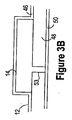
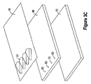
図3Aから図3Cは、保管構成要素12のための適切な構造を示す。図3Aは、保管構成要素12を示す斜視図である。図3Bは、図3A内のBで表示される鉤括弧の間に延びる線に沿った、図3Aに示す保管構成要素12の断面図である。図3Cは、カートリッジを組立てる前の、保管構成要素12を示す斜視図である。保管構成要素12は、カバー46、基部48、及び封止媒体50を備える。カバー46は、共通プラットホーム54から延びる、複数のポケット52を備える。カバー46は、各ポケット52がリザーバ14の一部を区画し、基部48がリザーバ14の別の部分を区画するように、基部48に結合される。複数の開口53がそれぞれ、基部48を通って延び、リザーバ14内に開口を設けるように配置される。
3A-3C show a suitable structure for the
封止媒体50は、リザーバ内の溶液を封止するように、穴を横断して延びる。封止媒体50は、1つ又は複数の層の材料を含むことができる。好ましい封止媒体50は、1次層を備え、1次層は、基部48内の開口53を封止し、穿刺された後に再封止することができる。例えば、封止層50は、隔壁を備えている。隔壁の使用により、リザーバ14に溶液を充填するプロセスを単純化することができる。例えば、2つの内腔を有する針を、隔壁を通し、かつ基部48内の開口53のうちの1つを通して、リザーバ14内へと挿入することができる。一方の内腔を通して、リザーバ14内の空気をリザーバ14から抜き出すことができ、もう一方の内腔を通して、溶液をリザーバ14内へと分配することができる。隔壁は、針がリザーバ14から引き抜かれた後、再封止する。
The sealing
カバー46のための適切な材料は、熱成形PVCフィルム、ポリエチレン、ポリウレタン、又は別のエラストマーなど、熱成形フィルムを含むが、これらに限定されない。基部48は、剛性材料で構築することができる。剛性材料は、溶液保管構成要素の形状を保存することができる。基部48のための適切な材料は、PVC、ポリエチレン、ポリウレタン、又は別のエラストマーを含むが、これらに限定されない。封止媒体の1次層のための適切な材料は、Silicone40D、ポリエチレン、又は別のエラストマーなど、隔壁材料を含むが、それらに限定されない。カバーを基部48に接合するための適切な技術は、RFシール、ヒートボンディング、又は接着剤を含むが、それらに限定されない。封止媒体50を基部48に接合するための適切な技術は、ヒートボンディング、レーザ溶接、エポキシ、又は(1つ又は複数の)接着剤を含むが、それらに限定されない。
Suitable materials for the
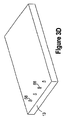
図3Dから図3Eは、図3Aから図3C内に示す保管構成要素とともに使用するのに適した、移送構成要素を示す。図3Dは、移送構成要素の一部を示す斜視図である。複数の穿刺機構56が、移送構成要素の片面から延びる。穿刺機構56は、封止媒体の封止完全性を分断することができる、分断機構として働く。図3Eは、図3Aの保管構成要素及び図3Dの移送構成要素を用いる、カートリッジを示す断面図である。断面は、穿刺機構56に沿っている。
3D-3E illustrate a transport component suitable for use with the storage component shown in FIGS. 3A-3C. FIG. 3D is a perspective view showing a portion of the transfer component. A plurality of
穿刺機構56は、保管構成要素内のポケットと位置合せされるように、移送構成要素上に配置される。保管構成要素12と移送構成要素13を結合するとき、穿刺機構56は、リザーバを封止する封止媒体50の一部を穿刺する。封止媒体50の穿刺によって、リザーバ内の溶液を、穿刺機構56と接触させて流すことが可能になる。内腔57が、1つ又は複数の穿刺機構16内を通り、移送構成要素13内へと延びる。したがって、内腔57は、リザーバから移送構成要素13内へと溶液を移送することができる。
The
図3Eに明らかなように、穿刺機構56は、保管構成要素12の基部48内の開口53と位置合せされるように、移送構成要素13上に配置される。基部48は、穿刺機構56によって穿刺することができない材料で、構築することができる。したがって穿刺機構は、開口を横断して延びる、封止媒体の一部を穿刺する。その結果、基部48は、穿刺機構56によって作り出される分断の位置を、封止媒体50の局部的な区域に限定する。
As can be seen in FIG. 3E, the
図4Aから図4Dは、分断機構16の別の一実施形態を用いるカートリッジを示す。図4Aは、図3AのBと表示される線に沿った、保管構成要素12の断面図である。保管構成要素12は、カバー46、基部48、及び封止媒体50を備える。図4Bは、図4Aに示す保管構成要素を、封止媒体50が定位置にない状態で示す底面図である。図4Cは、分断機構を有する移送構成要素の一部を示す斜視図である。図4Dは、図4Cの移送構成要素13上に示す分断機構16を用いる、カートリッジを示す断面図である。
4A-4D illustrate a cartridge that uses another embodiment of the
開口53は、リザーバ14からの流体通路を形成するように、保管構成要素12の基部48を通って延びる。基部48は、基部48の底部内へと延び、開口53を取り囲む凹部58を備える。移送構成要素を保管構成要素と結合させる前に、封止媒体50が、凹部58と開口53を横断して延び、したがって、図4Aに明らかなように、開口53を封止する。
The
図4Cに示す移送構成要素の片面から延びるリッジ59は、移送構成要素13の面上にカップを形成する。カップは、分断機構16として働く。保管構成要素12と移送構成要素13を結合するとき、カップは、図4Dに示すように、封止媒体50の一部を凹部58内へと押す。押下運動は、封止媒体50を伸張させる。封止媒体50は、伸張すると開くが伸張なしでは閉じる、1つ又は複数のチャネルを備えている。1つ又は複数のチャネルが、開口53及び/又は凹部58上に配置される。その結果、リザーバ14内の溶液が、リザーバ14から1つ又は複数のチャネルを通り、分断機構16と接触して流れることができる。したがって、カップによって開かれた1つ又は複数のチャネルは、封止媒体の封止完全性の分断部として働く。開口61は、カップの底部から、移送構成要素13内へと延びる。その結果、溶液は、リザーバ13から、封止媒体50内の1つ又は複数の分断部を通り、移送構成要素13内へと流れることができる。
The
カップとともに使用するための適切な封止媒体は、熱成形エラストマー(TPE)を含むが、これに限定されない。 Suitable sealing media for use with the cup include, but are not limited to, thermoformed elastomers (TPE).
図示の凹部58は、開口53を取り囲み、開口53の周りにリップ63が形成されるように開口から離隔されるが、凹部58は、開口から離隔しなくてもよい。例えば、凹部58は、リップ63が存在しないように、開口53内へと直接移行することができる。リップ63が存在しない場合、分断機構は、カップとして、尖っていない穿刺機構として、又はその2つの組合せとして構築することができる。
The illustrated
開口を取り囲む凹部が開示されるが、凹部58は、開口53を取り囲まずに、開口53に隣接して配置することができ、関連する分断機構16は、凹部58によって受けられるように構成されたリッジを含む。図4Cは、カップを備える単一の分断機構16を有する移送構成要素13を示すが、移送構成要素上の複数又はすべての分断機構が、カップを備えている。さらに、移送構成要素は、分断機構として働く、穿刺機構とカップの組合せを備えている。
Although a recess surrounding the opening is disclosed, the
ポケットが保管構成要素内のリザーバとして働く場合、ポケットは、外部圧力が加えられるときに変形可能とすることができる。カートリッジ10の動作中に、操作者は、溶液をリザーバ内から移送構成要素13内へと押し進めるために、ポケットに圧力を加えることができる。したがって、ポケットに加えられた圧力を用いて、溶液をリザーバから移送構成要素内へと移送することができる。PVC又はポリウレタンなど、保管構成要素12のカバー46のための材料は、ポケット52に圧力を加えることによってポケット52を変形させることを可能にする。
If the pocket serves as a reservoir in the storage component, the pocket can be deformable when external pressure is applied. During operation of the
上記で説明した各保管構成要素は、各開口53を横断して延びる単一の封止媒体を有するが、保管構成要素は、複数の封止媒体を備えることができ、各封止媒体は、1つ又は複数の開口を横断して延びることができる。
Each storage component described above has a single sealing medium extending across each
図示しないが、上記で開示した封止媒体50は、1次封止層を覆って配置される2次封止層を備えている。2次封止層は、保管構成要素12上の(1つ又は複数の)リザーバ14内へと溶液が装填された後に、保管構成要素に適用することができ、保管構成要素の移送及び/又は保管中に、封止媒体50を通る溶液の漏れを防止するように選択することができる。2次封止層は、カートリッジが組立てられる前に取り外すことができ、又は定位置に残すことができる。2次封止層のための適切な材料は、Mylarを含むがこれに限定されない。2次封止層は、接着剤で、又は表面張力を用いて、保管構成要素に取り付けることができる。
Although not shown, the sealing
図5Aから図5Cは、図2に関して開示したように動作するよう構成された、移送構成要素13のための適切な構造を示す。図5Aは、移送構成要素13を組立てる前の、移送構成要素13の部品を示す斜視図である。図5Bは、移送構成要素13を組立てる前の移送構成要素13の部品を示す、別の斜視図である。図5Bの視野は、図5Aの視野に対して上下が逆である。移送構成要素13は、カバー62と可撓性層64との間に配置された、基部60を備える。図5Cは、図5Bに示すカバー62の、Cで表示される線に沿った断面図である。
5A-5C illustrate a suitable structure for the
カバー62は、共通プラットホーム66から延びる、複数の分断機構16を備える。凹部68は、図5B、図5Cに明らかなように、カバー62の底部内へと延びる。以下で明らかになるように、これらの凹部68は、移送部材内の、移送チャネルの頂部及び側部、並びに産出物チャンバ26を区画する。例えば、凹部68の側部は、チャネルの側部及び産出物チャンバの側部として働く。カバー62はまた、分断機構16へと続く内腔への開口20としてそれぞれ働く、複数の開口20を備える。
The
基部60は、溶液内の作用物質の存在及び/又は量を検出するための、複数のセンサ70を備える。センサ70は、移送構成要素の組立時に、各センサが産出物チャンバ内に配置されるように、基部60上に配置される。図示のセンサは、作用電極72、参照電極74、及び対向電極76を備える。いくつかの例では、各電極は、単一層の導電性材料から形成される。適切な導電性材料は金を含むが、これに限定されない。導線78は、各電極と電気接点80との間に、電気接続をもたらす。別のセンサ構造が、本明細書にその全体が組み込まれる「Biological Identification System with Integrated Sensor Chip」という名称の、2001年5月5日出願の米国特許出願第09/848727号において開示されている。
The
移送構成要素の組立時は、カバー62を貫通して延びる開口82を通って、電気接点80にアクセスすることができる。図示しないが、保管構成要素は、開口82と位置合せされる複数の開口を備えているので、移送構成要素内の開口82と保管構成要素の開口の両方を通して、電気接点80にアクセスすることができる。あるいは、カートリッジの組立後に移送構成要素内の開口82が露出されたままとなるように、保管構成要素を構成することができる。これらの例では、移送構成要素内の開口82を通して、接点にアクセスすることができる。
During assembly of the transfer component, the
複数のリザーバ開口83が、基部60を通って延びる。以下で明らかになるように、リザーバ開口は、チャネル内の液体がそれを通って体積可変リザーバに出入りすることができる開口として働く。混合構成要素は、複数の体積可変リザーバを備える。さらに、体積制御デバイスがそれぞれ、体積可変リザーバを備えている。
A plurality of
複数の第1の弁チャネル84と第2の弁チャネル85が、基部60を通って延びる。以下で明らかになるように、各第1の弁チャネル84は、第2の弁チャネル85と接続されるので、第1の弁チャネル84と関連された第2の弁チャネル85は、同じ弁の一部である。さらに、第1の弁チャネル84は、弁入口として働き、第2の弁チャネル84は、弁出口として働く。移送構成要素の組立時に、第1の弁のための第1の弁チャネル84は、入力チャネルを通って流れる溶液が第1の弁チャネル内へと流れることができるように、入力チャネル28と位置合せされ、関連する第2の弁チャネル85は、第2の弁チャネル内の溶液が第1の共通チャネル内へと流れることができるように、第1の共通チャネルと位置合せされる。移送構成要素の組立時に、第2の弁のための第1の弁チャネル84は、第2の共通チャネルを通って流れる溶液が第1の弁チャネル内へと流れることができるように、第2の共通チャネルと位置合せされ、関連する第2の弁チャネルは、第2の弁チャネル内の溶液が独立チャネル内へと流れることができるように、独立チャネルと位置合せされる。移送構成要素の組立時に、入口弁、出口弁、及び遮断弁のための、第1の弁チャネル84は、第2の共通チャネルの一部を通って流れる溶液が第1の弁チャネル内へと流れることができるように、第2の共通チャネルの一部と位置合せされ、関連する第2の弁チャネルは、第2の弁チャネル内の溶液が第2の共通チャネルの別の部分内へと流れることができるように、独立チャネルと位置合せされる。
A plurality of
第1の通気開口86もまた、基部60を通って延びる。移送構成要素の組立時に、第1の通気開口86は、各通気チャネル内の空気が第1の通気開口86を通って流れることができるように、通気チャネル34と位置合せされる。可撓性層64は、複数の第2の通気開口87を備える。第2の通気開口87は、移送構成要素の組立時に、各第2の通気開口87が第1の通気開口86と位置合せされるように配置される。その結果、各通気チャネル34内の空気は、第1の通気開口86を通り、次いで第2の開口を通って流れることができる。したがって、各通気チャネル内の空気を、大気へと放出することができる。別の実施形態では、可撓性層64上に通気開口87が存在せず、通気チャネル34から放出される空気は、可撓性層64と通気チャネル34との間に閉じこめられる。
A first vent opening 86 also extends through the
図5Aから図5Dは、移送構成要素の組立時に各産出物チャンバ内に配置されるセンサを示すが、センサは、1つの産出物チャンバ内のみに、又は一部の産出物チャンバ内に、配置することができる。いくつかの例では、いずれの産出物チャンバも、上記で開示されるようなセンサを備えない。 FIGS. 5A-5D show a sensor that is placed in each product chamber during assembly of the transfer component, but the sensor can be placed in only one product chamber, or in some product chambers. can do. In some examples, none of the output chambers includes a sensor as disclosed above.
移送構成要素13は、基部60をカバー62及び可撓性層64に取り付けることによって、組立てることができる。移送構成要素13の組立時に、チャネルは、基部60、及びカバー62内の凹部68によって、部分的に区画される。例えば図5Dは、通気チャネル34を有する移送構成要素13の一部を示す断面図である。カバー62は、通気チャネル34の頂部と側部を区画し、基部60は、通気チャネル34の底部を区画する。
The
移送構成要素13は、通気チャネル34を通る溶液の流れを抑制しながら、空気が通気チャネル34を通って流れることができるように、構成される。いくつかの例では、通気チャネル34は、通気チャネル34を通る溶液の流れを防止し又は減少させながら、通気チャネル34を通る空気流を可能にするようにサイズ決めされる。
The
いくつかの例では、通気チャネル34は、1つ又は複数の狭窄区間89を備える。狭窄区間89は、通気チャネル内の障害物を貫通する、複数のダクト、導管、チャネル、又は細孔を備えている。ダクト、導管、チャネル、又は細孔はそれぞれ、溶液の流れを妨げながら空気の流れを可能にするように、サイズ決めすることができる。例えば、図5Eは、狭窄区間89を有する通気チャネル34を有するカバー62の一部を示す底面図である。図5Fは、Fで表示される線に沿った、狭窄区間89を示す断面図である。狭窄領域89は、溶液の流れを抑制し又は妨げながら、空気流を可能にするようにそれぞれサイズ決めされた、複数のダクト91を備える。いくつかの例では、ダクト91はそれぞれ、0.01μm2未満の断面積を有する。多数のダクト91の使用によって、溶液の流れを抑制するように構成された単一のダクト又は単一のチャネルを用いて達成することができるレベルを超えて、空気流の量を増大させることができる。その結果、多数のダクト91は、通気チャネル34を通して空気を流すことができる効率を、高めることができる。狭窄区間89は、通気チャネル34に沿ってどこにでも配置することもでき、単一の通気チャネル34に沿って、多数の狭窄区間を使用することができる。さらに、狭窄区間89は、通気チャネル34の全長にわたって延びることができる。
In some examples, the
あるいは、又はさらに、膜(図示せず)を、1つ又は複数の第2の通気開口87を覆うように可撓性層64上に配置することができる。膜は、膜を通る溶液の流れを防止しながら、膜を空気が通過することを可能にするように選択することができる。その結果、膜は、通気チャネル34を通る溶液の流れを妨害することができる。膜は、第2の通気開口に対して、局所的に配置することができる。例えば、膜は、1つ又は複数の第2の通気開口を覆うように配置することができる。あるいは膜は、可撓性層64上に配置され、複数の第2の通気開口87を覆う、材料の層とすることができる。膜のための適切な材料は、PTFE又は多孔性ポリマーを含むが、これらに限定されない。膜が用いられる場合、通気チャネルもまた、溶液流を抑制するように構成することができるが、そうしなくてもよい。例えば、1つ又は複数の狭窄区間89を、任意で膜とともに用いることができる。
Alternatively or additionally, a membrane (not shown) can be disposed on the
図5Aに示すカバー62は、共通プラットホーム66から延びる、複数の廃棄物出口構造93を備える。これらの出口構造は、移送構成要素の組立時に廃棄物チャネル36と位置合せされ、産出物チャンバからの廃棄溶液のための出口を形成する。出口構造は、カートリッジの組立時に保管構成要素上の空のリザーバ14を穿刺する、穿刺機構とすることができる。これらの例では、廃棄溶液は、カートリッジの動作中にリザーバ14内に流入する。あるいは、出口構造は、カートリッジの上方でアクセス可能とすることができる。例えば、出口構造は、保管構成要素を貫通し、又はその周りに、延びることができる。これらの例では、出口構造は、廃棄溶液をカートリッジから運び出す管又は別のデバイスと、連結させることができる。出口構造は、保管デバイス上に存在しなくてもよい。これらの例では、移送構成要素は、内部リザーバを備えることができ、その中に廃棄溶液が流入することができる。例えば、基部60及びカバー62は、廃棄物チャネル36がその中に流れ込む、廃棄物リザーバを区画することができる。
The
カバー62及び基部60は、射出成形、又は熱成形(thermal forming)を含むがこれに限定されない技術によって、形成することができる。カバー62や基部60のための適切な材料は、ポリカーボネート又はポリエチレンを含むが、これらに限定されない。適切な可撓性層64は、弾性膜又はシリコーンを含むが、これらに限定されない。カバー62と基部60を接合するための適切な技術は、レーザ溶接、熱ボンディング、又は接着剤の使用を含むが、これらに限定されない。基部60と可撓性層64とを接合するために、様々な技術を用いることができる。例えば、基部60と可撓性層64とを接合するために、レ―ザ溶接を使用することができる。以下から明らかになるように、可撓性層64が移送構成要素に接合されない、移送構成要素の区間が存在する。これらの区間は、シャドー・マスクをレーザ溶接と併せて使用することによって、形成することができる。電極、電気接点、及びリード線は、集積回路の製造技術を利用して基部上に形成することができる。
The
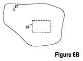
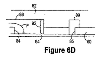
カバー62、基部60、及び可撓性層64は、移送機構内に弁を形成する。図6Aから図6Eは、図5Aから図5Bに示す移送構成要素の組立時に形成される、弁のうちの1つを示す。図6Aは、弁を備える移送構成要素の一部を示す平面図である。破線は、移送構成要素の内部に配置されたアイテムを示す。図6Bは、図6Aに示す移送構成要素の一部を示す底面図である。図6B内の破線は、可撓性層64が基部60に取り付けられない、弁区間91の位置を示す。図6Cは、図6Aに示すカートリッジの、Cと表示された鉤括弧の間に延びる線に沿った断面図である。図6Dは、図6Aに示すカートリッジの、Dと表示された鉤括弧の間に延びる線に沿った断面図である。
基部60内の第1の弁チャネル84は、入力チャネル内の溶液が第1の弁チャネル内へと流れることができるように、カバー62内の入力チャネル88と位置合せされる。したがって、第1の弁チャネル84は、入力チャネルの一部を区画する。基部60内の第2の弁チャネル85は、第2の弁チャネル内の溶液が出力チャネル内へと流れることができるように、カバー62内の出力チャネル89と位置合せされる。基部60及びカバー62は、入力チャネル88と出力チャネル89との間で、ともに障害物92を形成するように作用する。さらに、カバーは、入力チャネルと通気チャネルとの間に、第2の障害物を設ける。可撓性材料が、障害物92、第1の弁チャネル、及び第2の弁チャネルを覆って配置される。その結果、可撓性材料が、入力チャネルの一部、及び出力チャネルの一部を覆って配置される。さらに、可撓性材料は、通気チャネルの一部を覆って配置される。
The
図6Dから図6Eは、弁の動作を示す。弁を通る溶液流の所望の方向が、図6DのFで表示される矢印によって示される。可撓性層64は、弁の上方で溶液に限界圧力が加えられる前に溶液が障害物92の周りを流れないように、障害物92の十分近くに配置される。結果として、図6Dは、溶液が弁を通って流れる前の弁を示す。溶液が弁に向かって流れるとき、入力チャネル88内の空気は、図6CのAで表示された矢印によって示されるように通気チャネル90を通り、入力チャネル88を出ることができる。通気チャネル90は、空気が通気チャネル90を通って流れることができるように、構築される。いくつかの例では、溶液は、通気チャネルの長さの全部又は一部を通って流れることもできる。溶液が通気チャネル内へと流れる例では、図5に関連して議論したように、1つ又は複数の狭窄区間を、通気チャネルに沿って任意で配置することができる。その結果、通気チャネル90によって、空気及び/又は別の気体を入力チャネル88から放出させることが可能になる。通気チャネル90の一部が、弁区間内の入力チャネル88と平行であるものとして示される。通気チャネル90が平行であるという性質は、弁区間が溶液で満たされている間に、空気が流出し続けることを可能にする。
6D to 6E show the operation of the valve. The desired direction of solution flow through the valve is indicated by the arrow labeled F in FIG. 6D. The
弁の動作中に、可撓性層64と障害物92との間の変位が変化する。例えば、弁が閉位置から開くとき、又は弁がさらに開くとき、可撓性層64は、図6Eに示すように、障害物92から離れて動く。障害物92から離れる可撓性層64の運動によって、障害物92の周りの流体通路の体積が増大する。溶液にかかる上流の圧力が限界圧力を超え、あるいは、可撓性の膜が外力によって引き下げられると、図6EのFで表示される矢印によって示されるように、溶液が、障害物92の周りの流体通路を通って流れ始める。したがって、障害物から離れる可撓性層の運動によって、溶液が、入力チャネル88から出力チャネル89内に流入することが可能になる。
During the operation of the valve, the displacement between the
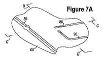
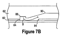
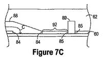
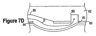
図7Aから図7Cは、カートリッジと共に使用するのに適した、弁の別の実施形態を示す。図7Aは、弁を備えるカバーの部分を示す斜視図である。図7Bは、図7Aに示すカバー62を備える移送構成要素を示す、Bで表示される鉤括弧の間に延びる線に沿った断面図である。図7Cは、図7Aに示すカバー62を備える移送構成要素を示す、Cで表示される鉤括弧の間に延びる線に沿った断面図である。
FIGS. 7A-7C illustrate another embodiment of a valve suitable for use with a cartridge. FIG. 7A is a perspective view showing a portion of a cover including a valve. FIG. 7B is a cross-sectional view along the line extending between the brackets indicated by B, showing the transfer component comprising the
基部60内の第1の弁チャネル84は、入力チャネル内の溶液が第1の弁チャネル内へと流れることができるように、カバー62内の入力チャネル88と位置合せされる。したがって、第1の弁チャネル84は、入力チャネルの一部を区画する。基部60内の第2の弁チャネル85は、第2の弁チャネル内の溶液が出力チャネル内へと流れることができるように、カバー62内の出力チャネル89と位置合せされる。したがって、第2の弁チャネル84は、出力チャネルの一部を区画する。基部60及びカバー62はともに、入力チャネル88と出力チャネル89との間で、障害物92を形成するように作用する。さらに、カバーは、入力チャネルと通気チャネルとの間に、第2の障害物を設ける。可撓性材料が、障害物92、第1の弁チャネル、及び第2の弁チャネルを覆って配置される。その結果、可撓性材料が、入力チャネルの一部、及び出力チャネルの一部を覆って配置される。さらに、可撓性材料は、通気チャネルの一部を覆って配置される。
The
図7Bから図7Dは、弁の動作を示す。弁を通る溶液流の所望の方向が、図7CのCで表示される矢印によって示される。可撓性層64は、弁の上流で溶液に限界圧力が加えられる前に溶液が障害物92の周りを流れないように、障害物92の十分近くに配置される。結果として、図7Cは、溶液が弁を通って流れる前の弁を示す。溶液が弁に向かって流れるとき、入力チャネル88内の空気は、図7BのBで表示された矢印によって示されるように通気チャネル90を通り、入力チャネル88を出ることができる。いくつかの例では、溶液はまた、通気チャネル内に流入することもできる。溶液が通気チャネル内へと流れる例では、図5に関連して議論したように、1つ又は複数の狭窄区間を、通気チャネルに沿って任意で配置することができる。したがって、通気チャネル90は、空気が通気チャネル90を通って流れることができるが、溶液が通気チャネル90を通って流れることは防止されるように、構築される。その結果、通気チャネル90によって、空気を入力チャネル88から流出させることが可能になる。
7B-7D show the operation of the valve. The desired direction of solution flow through the valve is indicated by the arrow labeled C in FIG. 7C. The
弁が開くと、可撓性層64は、図7Dに示すように障害物92から離れて動く。障害物92から離れる可撓性層64の運動によって、障害物92の周りに流体通路が作り出される。溶液にかかる上流の圧力が限界圧力を超え、あるいは、可撓性の膜が外力によって引き下げられると、図7DのDで表示される矢印によって示されるように、溶液が、障害物92の周りの流体通路を通って流れ始める。したがって、障害物から離れる可撓性層の運動によって、溶液が、入力チャネル88から出力チャネル89内に流入することが可能になる。
When the valve is opened, the
弁と交差する1つ又は複数のチャネルは、チャネルが弁に近づくにつれて減少する体積を有することができる。可撓性材料と反対側のチャネル部分は、図7Cに明らかなように、チャネルが弁に近づくにつれて可撓性材料に向かって傾斜することができる。例えば、弁のところで終端する入力チャネル88の部分は、弁に近づく方向で先細になる高さを有することができる。チャネルの高さは、チャネルに沿った点でのチャネルの高さであり、可撓性材料と直交する方向で測定され、チャネルを横断する可撓性材料から、可撓性材料から最も遠くに位置する反対側の点へと延びる。傾斜は、チャネルが弁のところで終端する位置にて、入力チャネル88の側部と底部との間に形成されるほぼ直角の隅部を減少させる。鋭い隅部は、空気を捕える可能性があるポケットとして働くおそれがある。傾斜は、隅部を平滑にすることを助け、したがって、これらのポケット内での気泡の形成を減少させることができる。
The one or more channels that intersect the valve can have a volume that decreases as the channel approaches the valve. The channel portion opposite the flexible material can be inclined towards the flexible material as the channel approaches the valve, as is apparent in FIG. 7C. For example, the portion of the
図7Aから図7Dはまた、弁に向かって先細になる通気チャネル90の高さを示す。このテーパ部は、通気チャネル90内の空気ポケットの形成を防止することができる。図7Aから図7Dは、入力チャネル88及び通気チャネル90の高さ内のテーパ部を示すが、入力チャネル88又は通気チャネル90がいずれもテーパ部を含まないように、入力チャネル88がテーパ部を含み通気チャネル90がテーパ部を含まないように、あるいは、通気チャネル90がテーパ部を含み入力チャネル88がテーパ部を含まないように、構築することができる。
7A-7D also show the height of the
弁のところの入力チャネル88に最も近い通気チャネル90の部分は、図7Aに明らかなように、入力チャネル88の隣接部分と平行にすることができる。平行な部分の長さは、任意で、入力チャネル88の隣接部分の幅とほぼ同じとすることができる。この構造によって、弁内の気泡の形成を減少させることができる。
The portion of the
入力チャネル88、出力チャネル89、及び通気チャネル90の、互いに対する配列は、図6Aから図7Dに示す配列から変化させることができる。例えば、チャネルの交点における、出力チャネルの部分及び入力チャネル88はいずれも、図2のVで表示される弁によって示すように、出力チャネルに対して平行にすることができる。図2は、入力チャネルの一部に沿って配置された弁を示すが、入力チャネルと、通気チャネルと、共通チャネルとの交点にて弁が配置されるように、弁を構築することができる。チャネル配列の柔軟性によって、単一カートリッジ上に配置することができるフィーチャの数を、増加させることができる。
The arrangement of the
いくつかの例では、第2の弁チャネルは、図6Aに明らかなように、実質的に円形を有する。円形は、出力チャネルの幅よりも大きい直径を有することができる。これらの例では、出力チャネルは、図6A、図7Aに明らかなように、任意で隆起を有することができる。隆起は、第2の弁チャネルの壁部と実質的に面一な、出力チャネルの壁部を作り出すように構成することができる。面一であるという特徴によって、出力チャネルの壁部と第2の弁チャネルの壁部との間の段差の形成から生じるおそれがある、空気ポケットの形成を減少させることができる。 In some examples, the second valve channel has a substantially circular shape, as is apparent in FIG. 6A. The circle can have a diameter that is greater than the width of the output channel. In these examples, the output channel can optionally have a ridge, as is apparent in FIGS. 6A, 7A. The ridge can be configured to create a wall of the output channel that is substantially flush with the wall of the second valve channel. The flushness feature can reduce the formation of air pockets that can result from the formation of a step between the wall of the output channel and the wall of the second valve channel.
図6Aから図7Dで開示された弁は、図2の文脈で説明した第1の弁38とすることができる。弁が第1の弁38として働く場合、入力チャネル28は、入力チャネル88とすることができ、第1の共通チャネル29は、出力チャネル89とすることができ、通気チャネル34は、通気チャネル90とすることができる。あるいは、弁を、入力チャネルの一部に沿って配置することができる。例えば、入力チャネル28の一部は、入力チャネル88とすることができ、入力チャネル28の別の部分は、出力チャネル89とすることができ、通気チャネル34は、通気チャネル90とすることができる。
The valve disclosed in FIGS. 6A to 7D may be the
図6Aから図7Dで開示される弁は、弁から通気チャネル34を取り外すことによって、図2の文脈で説明したような、第2の弁40、入口弁41、出口弁42、及び/又は遮断弁43として働くように、適合させることができる。弁が第2の弁40として働く場合、第2の共通チャネル32は入力チャネル88とすることができ、独立チャネル30は出力チャネル89とすることができる。あるいは、弁は、独立チャネル30の一部に沿って配置することができる。例えば、独立チャネル30の一部は、入力チャネル88とすることができ、独立チャネル30の別の部分は、出力チャネル89とすることができる。
The valve disclosed in FIGS. 6A-7D can be removed by removing the
図5A、図5Bに示す移送構成要素は、図6Aから図6Eに従って構築された弁を備えるが、弁のうちの1つ、複数の弁、又はすべての弁を、図7Aから図7Eに従って構築することができる。 The transfer component shown in FIGS. 5A and 5B includes a valve constructed in accordance with FIGS. 6A through 6E, but one of the valves, multiple valves, or all valves are constructed in accordance with FIGS. 7A through 7E. can do.
溶液にかかる上流圧力を、可撓性層64を変形させるのに十分に上昇させることによって、かつ/又は、可撓性層64を障害物92から離して動かすために、外部機構を用いることによって、上記弁を開くことができる。上流圧力は、入力チャネルと流体連通する溶液を収容する、リザーバ14を圧迫することによって上昇させることができる。適切な外部機構の一例は真空である。真空は、可撓性層64を障害物92から離して引っ張るために用いることができる。
By increasing the upstream pressure on the solution sufficiently to deform the
可撓性層64は、障害物92と接触して示されているが、上流の溶液に正圧が加えられていないときに、可撓性層64が障害物92から離隔されるように、移送構成要素を構築することができる。可撓性層64と障害物92との間の間隙は、限界圧力が実現されるまで、溶液が障害物92を越えて流れることが溶液の表面張力によって防止されるよう、十分に小さくすることができる。これらの例では、障害物92から離れる可撓性層64の運動は、障害物92の周りの通路の体積を増大させる働きをする。
While the
弁を通る溶液の流れを生み出すために必要とされる限界圧力を制御することができる。より剛性が高く、かつ/又はより厚い可撓性層64は、限界圧力を上昇させることができる。上流の溶液に正圧が加えられていないときに、可撓性層64を障害物92のより近くへと動かすことによって、限界圧力を上昇させることができる。1つ又は複数の弁チャネル84のサイズを縮小させることによって、障害物92の周りの流体通路を狭めることができ、また、限界圧力も上昇させることもできる。さらに、1つ又は複数の弁チャネル84のサイズを増大させることによって、障害物92の周りの通路の体積を増大させることができ、また、限界圧力を低減することもできる。
The critical pressure required to create a solution flow through the valve can be controlled. A stiffer and / or thicker
入口弁チャネル84と出口弁チャネル85の相対的なサイズもまた、弁の性能に影響を与える。例えば、出口弁チャネル85の断面積の、入口弁チャネル84の断面積に対する比は、弁の性能に影響を及ぼす可能性がある。この比率が1未満である場合、弁を通る逆流を減少させることができる。さらに、比率を低減することは、逆流を減少させる働きをする。いくつかの例では、入力チャネル及び/又は出口チャネルは複数の流路を有する。例えば、出口流チャネルは、基部を貫通する複数の穴を備えている。これらの例では、出口チャネルは、各流路のすべての断面積の合計である。
The relative size of the
入力チャネルと共通チャネル32との間に配置された弁の文脈で弁を開示するが、図示の弁構造は、移送構成要素内の別の弁に適合させることができる。
Although the valve is disclosed in the context of a valve disposed between the input channel and the
上記の説明図は、弁に接続された通気チャネル34を示すが、弁チャネル34は別の様々な位置に配置することができる。例えば、通気チャネル34は、弁の前の入力チャネル内に配置することができる。
Although the above illustration shows a
図5A、図5Bの移送構成要素は、各弁を形成する単一の可撓性材料を示すが、移送構成要素は、複数の可撓性材料を含むことができ、各可撓性材料はそれぞれ、1つの弁又は複数の弁内に含むことができる。 Although the transfer component of FIGS. 5A and 5B shows a single flexible material forming each valve, the transfer component can include multiple flexible materials, each flexible material being Each can be contained within a single valve or multiple valves.
図8A、図8Bは、可撓性層64を弁内で障害物92から離して動かすために外部機構を用いる、上記で開示したように構築されたカートリッジの動作を示す。図8Aは、多岐管96上に配置されたカートリッジを含む、システムの側面図である。いくつかの例では、カートリッジは、多岐管上で不動化される。カートリッジを多岐管上で不動化させるために、多種多様なデバイスを用いることができる。図8Bは、図8Aに示すシステムの断面図である。多岐管96は複数のポート98を備える。ポートは、カートリッジ上の弁と位置合せされる。多岐管96は、1つ又は複数のポート上で、それぞれ独立して真空吸引することができるように構成される。ポート98にて吸引される真空は、ポートと位置合せされた弁を、図8Bの破線及びAで表示された矢印によって示されるように、完全に又は部分的に開くのに十分な大きさとすることができる。その結果、多岐管96を用いて、カートリッジ上の弁を選択的に開くことができる。さらに、又はあるいは、多岐管は、ポート上に正圧を生み出すように構成することができる。正圧によって、カートリッジの動作中に、弁を閉じたままに保つことができる。例えば、溶液が混合構成要素内へと流される間に出口弁を閉じたままに保つように、多岐管を動作させることができる。
8A and 8B illustrate the operation of a cartridge constructed as disclosed above using an external mechanism to move the
図8A、8Bにおいて、多岐管96を開示するが、上記で開示したように構築されるカートリッジは、弁を開閉するための外部機構を使用することなく、動作することができる。結果的に、多岐管96は任意選択である。
8A and 8B, a manifold 96 is disclosed, but a cartridge constructed as disclosed above can operate without the use of an external mechanism for opening and closing the valve. As a result,
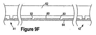
図9Aから図9Dは、図5A、5Bに示す移送構成要素の組立時に形成される、混合構成要素を示す。図9Aは、混合要素を備える移送構成要素の一部を示す平面図である。図9Bは、図9Aに示す移送構成要素の部分を示す、底面図である。図9Cは、図9Bに示すカートリッジの、Cと表示された鉤括弧の間に延びる線に沿った断面図である。図9Dは、図9Bに示すカートリッジの、Dと表示された鉤括弧の間に延びる線に沿った断面図である。図示のために、図9Aでは、移送構成要素を透明なものとして扱う。したがって、図9A内の実線は、カバー62上に含まれるが移送構成要素の内部に配置されるフィーチャを示す。さらに、図9A内の破線は、基部60上の移送構成要素の内部に配置されたアイテムを示す。この場合も構成要素は、図9Bでは透明であるとして扱われる。実線は、カバー62上及び基部60上に含まれ移送構成要素の内部に配置される、フィーチャを示す。
9A-9D illustrate the mixing component formed during assembly of the transfer component shown in FIGS. 5A and 5B. FIG. 9A is a plan view showing a portion of a transfer component comprising a mixing element. 9B is a bottom view showing portions of the transfer component shown in FIG. 9A. 9C is a cross-sectional view of the cartridge shown in FIG. 9B along the line extending between the brackets labeled C. FIG. 9D is a cross-sectional view of the cartridge shown in FIG. 9B along the line extending between the brackets labeled D. FIG. For illustration purposes, FIG. 9A treats the transfer component as transparent. Thus, the solid line in FIG. 9A shows features that are included on the
混合構成要素は、複数の体積可変リザーバを備える。図9B内の破線は、可撓性層64が基部60に取り付けられない、体積可変リザーバ100の外周を示す。図9C、図9D内の、Fで表示される鉤括弧は、可撓性層64が基部60に取付けられない位置を示し、したがって、体積可変リザーバの位置を示す。図9Aから図9Dに示す体積可変リザーバは、体積ゼロで示される。図9Eは、各体積可変リザーバが溶液を収容する、図9Dの混合構成要素を示す。したがって、各体積可変リザーバは、ゼロではない体積を有する。
The mixing component comprises a plurality of variable volume reservoirs. The dashed line in FIG. 9B shows the outer periphery of the
混合構成要素は、2つの体積可変リザーバ100を備える。混合チャネル102は、体積可変リザーバ100間に液体連通をもたらす。混合チャネル102は、入口チャネル104及び/又は出口チャネル106の断面積より大きい断面積を有することができる。リザーバ開口83が、基部60を通って延び、混合チャネル102内に配置される。したがって、リザーバ開口83は、導管として働き、それを通って溶液は、混合チャネル102から体積可変リザーバ100に入ることができ、かつ/又は、体積可変リザーバ100から混合チャネルに入ることができる。以下でより詳細に説明されるように、体積可変リザーバの体積を増減させるために、多数の機構が利用可能である。
The mixing component comprises two
図9Fから図9Kは、溶液を混合するように混合構成要素を動作させる方法を示す。図9Fは、混合構成要素を示す断面図である。入口弁41と出口弁42もまた、図9Fに示される。入口弁41と出口弁42を、混合構成要素と別個であるとして示すが、入口弁41及び/又は出口弁42は、混合構成要素内に組み込むことができる。
9F-9K illustrate a method of operating the mixing component to mix the solution. FIG. 9F is a cross-sectional view showing the mixing component.
複数種類の溶液を混合構成要素内へと移送する間は、図9Gに示すように、出口弁42が閉じられ、入口弁が開かれる。Aで表示された矢印によって示されるように、第1の溶液が、入口弁41を通って混合構成要素内へと移送される。第1の溶液が両方の体積可変リザーバ内に流入するように、又は第1の溶液が一方の体積可変リザーバ内に流入するように、体積可変リザーバを動作させることができる。図示の方法は、動作させられる体積可変リザーバを示し、体積可変リザーバは、第1の溶液が、一方の体積可変リザーバに流れ、したがって体積可変リザーバの体積を、Bで表示される矢印が示すように増大させるように、動作させられる。所望の体積の第1の溶液が、混合構成要素内へと移送された後に、第2の溶液が、入口弁41を通って混合構成要素内へと移送される。第1の溶液と第2の溶液の間の界面が、図9GのIで表示される線によって示される。所望の体積の第2の溶液が、混合構成要素内へと移送される。さらなる溶液を、混合構成要素内へと任意で移送することができる。様々な溶液が組み合わさって、混合構成要素内で産出物溶液を形成する。
During the transfer of multiple types of solutions into the mixing component, the
所望の数の溶液が混合構成要素内へと移送された後に、図9Hに示すように入口弁が閉じられる。図9Hに示すような、入口弁41と出口弁42の閉鎖は、混合プロセス中に混合構成要素内の溶液をカートリッジの別の区間から遮断するのに役立つ。
After the desired number of solutions has been transferred into the mixing component, the inlet valve is closed as shown in FIG. 9H. Closure of the
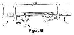
図9IのAで表示される矢印によって示すように、第1の体積可変リザーバ100Aの体積が減少させられる。さらに、又はあるいは、図9IのBで表示される矢印によって示すように、第2の体積可変リザーバ100Bの体積を、増大させることができる。これらの作用の結果、少なくとも一部の産出物溶液の、第1の体積可変リザーバ100Aから第2の体積可変リザーバ100Bへの移送が生じる。
As indicated by the arrow displayed at A in FIG. 9I, the volume of the first
上記ステップは、図9Jに示すように、産出物溶液の少なくとも一部を第1の体積可変リザーバへと戻すために、逆行させることができる。例えば、図91のAで表示される矢印によって示すように、第1の体積可変リザーバ100Aの体積を、増大させることができる。さらに、又はあるいは、図9JのBで表示される矢印によって示すように、第2の体積可変リザーバ100Bの体積を、減少させることができる。これらの作用の結果、少なくとも一部の産出物溶液の、第2の体積可変リザーバ100Bから第1の体積可変リザーバ100Aへの移送が生じる。
The above steps can be reversed to return at least a portion of the product solution back to the first variable volume reservoir, as shown in FIG. 9J. For example, the volume of the first
体積可変リザーバ間を前後する産出物溶液の移送によって、溶液が混合される。混合の質は、循環の回数が増大するにつれて高まる。例えば、産出物溶液は、好ましくは、少なくとも1回、10回、又は100回、体積可変リザーバのうちの1つへと移送される。したがって、産出物溶液は、所望の程度の混合が実現されるまで、体積可変リザーバの間で循環させられる。所望の程度の混合が実現された後に、出口弁が開かれ、体積可変リザーバ内の体積が低減させられる。体積の減少によって、産出物溶液が、図9KのAで表示される矢印で示すように混合構成要素の外へと移送される。 The solution is mixed by transfer of the product solution back and forth between the variable volume reservoirs. The quality of mixing increases as the number of circulations increases. For example, the product solution is preferably transferred to one of the variable volume reservoirs at least once, 10 times, or 100 times. Thus, the product solution is circulated between the variable volume reservoirs until the desired degree of mixing is achieved. After the desired degree of mixing is achieved, the outlet valve is opened and the volume in the variable volume reservoir is reduced. By reducing the volume, the product solution is transferred out of the mixing component as shown by the arrow labeled A in FIG. 9K.
上記の方法では、入口弁によって、入口チャネルを通る保管構成要素内の保管リザーバへの、溶液の逆流が低減する。ただしこの機能は、第1の弁を用いて実現することもできる。結果的に、入口弁は任意選択である。 In the above method, the inlet valve reduces the backflow of solution through the inlet channel to the storage reservoir in the storage component. However, this function can also be realized by using the first valve. As a result, the inlet valve is optional.
図示の混合構成要素は、任意で、それを迂回することができるという利点を有する。例えば、混合構成要素を通して溶液が移送される間に、各体積可変リザーバを、閉位置にすることができる。その結果、溶液は、体積可変リザーバ内に流入することなく、混合構成要素を通って流れる。 The mixing component shown has the advantage that it can optionally be bypassed. For example, each variable volume reservoir can be in a closed position while the solution is transferred through the mixing component. As a result, the solution flows through the mixing component without flowing into the variable volume reservoir.
混合構成要素へと続き、又はそこから延びるチャネルのための、別の構成が可能である。例えば、多数の入口チャネルが、溶液を混合チャネル内へと移送することができる。ただし、単一の入口チャネル及び単一の出口チャネルを有する混合構成要素の構成は、混合構成要素の動作の複雑性を低減する。 Other configurations are possible for the channel leading to or extending from the mixing component. For example, multiple inlet channels can transfer the solution into the mixing channel. However, the configuration of a mixing component having a single inlet channel and a single outlet channel reduces the operational complexity of the mixing component.
上記方法は、体積可変リザーバの体積の、増大及び/又は低減を必要とする。体積可変リザーバの体積を増大及び/又は低減させるために、様々な機構を用いることができる。例えば、図9Lは、図8Aの多岐管96上に配置されたカートリッジを示す。いくつかの例では、カートリッジは、多岐管上で不動化される。カートリッジを多岐管上で不動化させるために、多種多様なデバイスを用いることができる。多岐管96は、体積可変リザーバ100と位置合せされるポート98を備える。多岐管96は、ポートを通して真空吸引することができるように構成される。ポート98にて吸引される真空は、体積可変リザーバ100の体積を増大させるのに十分な大きさとすることができる。さらに、又はあるいは、多岐管は、ポート内に正圧を生み出すように構成することができる。正圧は、体積可変リザーバの体積を低減させ、かつ/又は、体積可変リザーバを閉じたまま保つのに、十分な大きさとすることができる。さらに、又はあるいは、図9Mに示すように、ポート98は、可撓性層64を操作するための機械的デバイス110を備えている。デバイス110は、体積可変リザーバの体積が低減されるように、可撓性層64を基部60に向かって押すことができ、かつ/又は、体積可変リザーバの体積が増大されるように、可撓性層64を基部60から離して引っ張ることができる。適切な機械的デバイスは、磁気アクチュエータ、電動アクチュエータ、及び空気圧アクチュエータを含むが、これらに限定されない。
The above method requires increasing and / or decreasing the volume of the variable volume reservoir. Various mechanisms can be used to increase and / or decrease the volume of the variable volume reservoir. For example, FIG. 9L shows a cartridge disposed on the
体積可変リザーバの体積を変化させるために、多岐管など外部デバイスが用いられる場合、溶液を体積可変リザーバ内へと移送するために、様々な機構を用いることができる。例えば、体積可変リザーバと液体連通する移送チャネル内に溶液がある間に、体積可変リザーバの体積を増大させることができる。体積可変リザーバの体積を増大させることによって、溶液が体積可変リザーバ内へと引き込まれる。あるいは、例えば、体積可変リザーバと液体連通する移送チャネル内に溶液が存在しないうちに、体積可変リザーバの体積を増大させることができる。溶液は、開いた体積可変リザーバ内に流入することができる。 If an external device such as a manifold is used to change the volume of the variable volume reservoir, various mechanisms can be used to transfer the solution into the variable volume reservoir. For example, the volume of the variable volume reservoir can be increased while the solution is in a transfer channel in fluid communication with the variable volume reservoir. By increasing the volume of the variable volume reservoir, the solution is drawn into the variable volume reservoir. Alternatively, for example, the volume of the variable volume reservoir can be increased while no solution is present in the transfer channel in fluid communication with the variable volume reservoir. The solution can flow into an open variable volume reservoir.
いくつかの例では、体積可変リザーバの体積を変化させるために、多岐管などの外部デバイスは必要とされない。例えば、溶液が体積可変リザーバ内に流入し、体積可変リザーバの体積が増大するまで、体積可変リザーバへの導管を有する移送チャネル内の溶液にかかる圧力を増大させることができる。あるいは、溶液が体積可変リザーバから流出し、体積可変リザーバの体積が低減されるまで、体積可変リザーバへの導管を有する移送チャネル内の溶液にかかる圧力を低下させることができる。 In some examples, no external device such as a manifold is required to change the volume of the variable volume reservoir. For example, the pressure on the solution in the transfer channel having a conduit to the variable volume reservoir can be increased until the solution flows into the variable volume reservoir and the volume of the variable volume reservoir increases. Alternatively, the pressure on the solution in the transfer channel having a conduit to the variable volume reservoir can be reduced until the solution flows out of the variable volume reservoir and the volume of the variable volume reservoir is reduced.
図10Aから図10Dは、図5A、5Bに示す移送構成要素の組立時に形成される、体積制御デバイス44を示す。図10Aは、体積制御デバイス44を備える移送構成要素の一部を示す平面図である。図10Bは、図10Aに示す移送構成要素の一部を示す底面図である。図10Cは、図10Bに示すカートリッジの、Cと表示された鉤括弧の間に延びる線に沿った断面図である。図示のために、図10Aでは、移送構成要素を透明なものとして扱う。したがって、図10A内の実線は、カバー62上に含まれるが移送構成要素の内部に配置される、フィーチャを示す。さらに、図10A内の破線は、基部60上の移送構成要素の内部に配置されたアイテムを示す。図10Bでも同様に、移送構成要素は、透明であるとして扱われる。実線は、カバー62上及び基部60上に含まれ移送構成要素の内部に配置された、フィーチャを示す。
10A through 10D show a
体積制御デバイスは、体積可変リザーバを備える。図10B内の波線は、体積可変リザーバ100の外周を示す。可撓性層64は、体積可変リザーバ100の内部では、基部60に取り付けられない。図10C、図10DにおいてFで表示される鉤括弧は、可撓性層64が基部60に取付けられない位置を示し、したがって、体積可変リザーバの位置を示す。図10Aから図10Cに示す体積可変リザーバは閉位置で示され、したがって、体積ゼロを有する。図10Dは、体積可変リザーバ100が開位置にあり、溶液を収容する、体積制御デバイス44を示す。したがって、図10Dの体積可変リザーバは、ゼロではない体積を有する。
The volume control device comprises a variable volume reservoir. The wavy line in FIG. 10B shows the outer periphery of the
体積制御デバイス44は、移送チャネル112内のリザーバ開口を備える。図10Aから図10Dに示す体積制御デバイス44は、図2に示す体積制御デバイス44のいずれかに含めることができる。したがって、移送チャネル112は、図2の第2の共通チャネル32とすることができる。リザーバ開口83は、導管として働き、それを通って、移送チャネル112内の溶液は、体積可変リザーバ100から移送チャネル112に入ることができ、かつ/又は、体積可変リザーバ100から移送チャネル112に入ることができる。体積可変リザーバ100の体積は、図9L、図9Mの文脈で開示されるように、増大及び/又は低減させることができる。
The
図10Eから図10Gは、別々の産出物チャンバへと移送される溶液の体積を制御するための、体積制御デバイスの動作を示す。図示の体積制御デバイスは、図10Aから図10Dに従って構築され、図2に示すように配列される。したがって、図2の遮断弁43は、弁制御デバイスの間に配置されて示される。さらに、図2の出口弁42を示す。図2に示す第2の弁40もまた、本方法で用いられるが、図示されない。
FIGS. 10E-10G illustrate the operation of the volume control device to control the volume of solution transferred to separate product chambers. The illustrated volume control device is constructed according to FIGS. 10A-10D and arranged as shown in FIG. Accordingly, the shut-off
出口弁42と遮断弁43が開かれ、図10EのAで表示される矢印によって示すように、溶液が体積可変リザーバ内へと移送される。体積可変リザーバ内への溶液の移送中に、独立チャネル(図2の30)及び/又は産出物チャンバ(図2の26)内への溶液の流れを低減し、又は防止するために、第2の弁(図2の40)が閉じられる。
遮断弁43は、図10Fに示すように閉じられる。遮断弁43を閉じることによって、VC1で表示される体積制御デバイス44と、VC2で表示される体積制御デバイス44との間の、液体連通が閉じられる。体積制御デバイスから混合構成要素へと向かう溶液の逆流を防止するために、出口弁42もまた閉じられる。
The shut-off
第2の弁(図2の40)が、一斉に、又は1つずつ開かれる。第2の弁(図2の40)を開くことによって、各産出物チャンバ(図2の26)と、関連する体積可変リザーバ100との間の液体連通が開かれる。その結果、第2の弁を開けながら、遮断弁43と出口弁42を閉じることによって、各産出物チャンバと、関連する体積制御デバイスとの間の液体連通を開きながら、体積制御デバイス間の液体連通が閉じられる。さらに、この配列はまた、各体積制御デバイスと少なくとも1つの産出物チャンバとの間の、液体連通を閉じる。例えば、この配列は、図2においてVC1と表示された体積制御デバイス44と、SC2と表示された産出物チャンバとの間の、液体連通を停止させる。
The second valves (40 in FIG. 2) are opened all at once or one at a time. By opening the second valve (40 in FIG. 2), fluid communication between each output chamber (26 in FIG. 2) and the associated
体積可変リザーバ100と産出物チャンバとの間に液体連通が開かれた後に、図10Gに示すように、体積可変リザーバ100の体積を低減させることができる。体積可変リザーバの体積を低減させることによって、体積可変リザーバ100から産出物チャンバ内へと、溶液が流入させられる。これは、溶液を受け取るべき各産出物チャンバへと溶液が移送されるまで、各体積可変リザーバで繰り返すことができる。
After fluid communication is opened between the
体積制御デバイス44及び産出物チャンバから移送される、溶液の量を制御するために、多種多様の機構を用いることができる。例えば、体積制御デバイス100の体積は、所望の量の溶液を産出物チャンバへと移送するための知られた量まで、低減させることができる。あるいは、溶液が体積可変リザーバ内へと移送される間かつ/又は前に、体積可変リザーバを、体積可変リザーバが閉じられるときに所望の量の溶液を産出物チャンバへと移送するための、知られた体積まで開くことができる。その結果、溶液を受け取った後の体積可変リザーバ100を閉じることによって、所望の体積の溶液が、産出物チャンバへと移送される。
A wide variety of mechanisms can be used to control the amount of solution transferred from the
各産出チャンバへと移送される溶液の体積は、同一又は別々とすることができる。その結果、溶液を産出物チャンバへと移送するために、別々の体積可変リザーバを、別々の体積へと低減することができる。さらに、又はあるいは、溶液が、体積可変リザーバ内へと移送される前又は間に、別々の体積可変リザーバを、別々の体積まで開くことができる。 The volume of solution transferred to each output chamber can be the same or different. As a result, separate variable volume reservoirs can be reduced to separate volumes in order to transfer the solution to the product chamber. Additionally or alternatively, separate variable volume reservoirs can be opened to separate volumes before or during the solution is transferred into the variable volume reservoir.
上記方法における出口弁42の機能は、移送構成要素内の別の弁を用いて実現することができる。例えば、出口弁は、溶液の逆流を、防止又は低減する。ただしいくつかの例では、これは、図2に示す入口弁41及び/又は第1の弁38を用いて実現することができる。あるいは、この機能をもたらすために、追加の遮断弁を第2の共通チャネル32に沿って配置することができる。結果的に、上記方法における出口弁の使用は、任意選択である。
The function of the
溶液が、産出物チャンバの一部のみに移送され、又は産出物チャンバのうちの1つのみに移送されるように、上記方法を適合させることができる。一例として、SC2と表示された産出物チャンバのみに溶液を移送することが望ましい場合、上記方法は、VC1と表示された体積制御デバイス内の体積可変リザーバを開かずに、実行することができる。SC1と表示された産出物チャンバへと移送することが望ましい場合、上記方法を、遮断弁43を開かずに実行することができる。さらに、体積制御デバイスによって提供される体積制御機能は、各体積可変リザーバが閉位置にある状態で体積制御デバイスを動作させることによって、回避することができる。その結果、溶液は、体積可変リザーバ内へと流入せず、体積制御機能が、回避される。
The method can be adapted such that the solution is transferred to only a portion of the product chamber, or to only one of the product chambers. As an example, if it is desired to transfer the solution only output product chamber labeled SC 2, the method, without opening the variable volume reservoir within the volume control device labeled VC 1, it is performed it can. If it is desired to transfer to the SC 1 and displayed output product chamber, the method may be performed without opening the shut-off
図10Eから図10Fの文脈で説明された方法は、図2に示した移送構造に限定されない。例えば、移送構造は、独立チャネル30間の第2の共通チャネル32に沿って配置された、複数の体積制御デバイスを備えている。移送構成要素はまた、第2の共通チャネル32に沿って配置された、追加の遮断弁43を含むことができる。遮断弁及び体積制御デバイスは、遮断弁を閉じることによって、体積制御デバイスの様々な部分の間の液体連通を閉じる一方で、各産出物チャンバと体積制御デバイスの別の一部との間の液体連通を開くように、配列することができる。
The method described in the context of FIGS. 10E to 10F is not limited to the transfer structure shown in FIG. For example, the transfer structure comprises a plurality of volume control devices disposed along a second
図11Aは、図5A、5Bに示す移送構成要素の組立時に形成される、通気デバイス(図2の35)を示す。図11Aは、移送構成要素を示す断面図である。通気デバイスは、可撓性層62内の第2の通気開口87と位置合せされる、基部60内の第1の通気開口86を備える。第1の通気開口86と第2の通気開口87は、通気チャネル34と位置合せされる。その結果、各通気チャネル34内の空気は、第1の通気開口86と第2の通気開口87を通り、大気中又は閉込めデバイス内へと流れることができる。
FIG. 11A shows a venting device (35 in FIG. 2) formed during assembly of the transfer component shown in FIGS. 5A and 5B. FIG. 11A is a cross-sectional view showing the transfer component. The vent device comprises a first vent opening 86 in the base 60 that is aligned with a second vent opening 87 in the
移送構成要素は、別の通気デバイスを備えている。図11B、11Cは、体積可変リザーバを備える通気デバイスを有する移送構成要素を示す。図11Bは、移送構成要素を示す断面図である。リザーバ開口83が、基部60を通って延び、通気チャネル34内に配置される。したがって、リザーバ開口83は、導管として働き、それを通って流体が、通気チャネル34から体積可変リザーバ100に入ることができ、かつ/又は、体積可変リザーバ100から通気チャネル34に入ることができる。通気チャネル34内の圧力が上昇するにつれて、通気チャネル34内の流体が、体積可変リザーバ100に入り、図11Cに示すように、体積可変リザーバの体積が増大する。その結果、体積可変リザーバは、リザーバからの流体が、カートリッジ内に収容されることを可能にする。
The transfer component comprises another venting device. 11B and 11C show a transfer component having a venting device with a variable volume reservoir. FIG. 11B is a cross-sectional view showing the transfer component. A
通気デバイス内の体積可変リザーバは、上記で開示したような多岐管など外部デバイスを使用して、開閉することができる。ただし、体積可変リザーバは、通気チャネル内の圧力を上昇させた結果として開くことができるので、外部デバイスは任意選択である。 The variable volume reservoir in the vent device can be opened and closed using an external device such as a manifold as disclosed above. However, the external device is optional since the variable volume reservoir can be opened as a result of increasing the pressure in the vent channel.
各リザーバに関連する単一の分断機構を有する、カートリッジを示すが、カートリッジは、各リザーバに関連する複数の分断機構を備えることができ、かつ/又は、保管構成要素の基部は、各リザーバに関連する複数の開口を備えている。 Although a cartridge is shown having a single severing mechanism associated with each reservoir, the cartridge may comprise a plurality of severing mechanisms associated with each reservoir and / or the base of the storage component is in each reservoir. A plurality of associated openings are provided.
上記で説明した移送構成要素13は、基部60、カバー62、及び可撓性層64を備えるが、移送構成要素は、より多くの構成要素又はより少なく構成要素から、構築することができる。例えば、カバー62は、多数の層から構築することができる。移送構成要素を、追加の構成要素からどのように構築することができるかという一例として、図5C内の破線は、カバー62を形成するために互いに接合することができる2つの層に、カバーを分割する。この実施形態では、チャネルは、上層を貫通して延びる穴によって形成され、底部層は、チャネルの底部又は頂部として働く基盤とすることができる。さらに、移送構成要素は、カバー62及び基部60を一体化することによって、より少ない構成要素から構築することができる。さらに、チャネル又はチャンバの一部が、移送構成要素13の全部又は一部内の可撓性層64によって区画される場合、基部60は、任意選択である。
The
上記で開示した、体積可変リザーバの最大体積は、可撓性層64が基部60に取付けられない面積寸法、可撓性層64の可撓性、及び/又は多岐管96内のポート98の体積の、関数とすることができる。上記で開示された体積可変リザーバはそれぞれ、同一の最大体積を有することができ、又は、別々の最大体積を有することができる。例えば、混合構成要素内の体積可変リザーバは、体積制御デバイス内の体積可変リザーバと異なる最大体積を有することができる。混合構成要素内の体積可変リザーバの最大体積は、好ましくは、2μl、20μl、又は2mlより大きい。少なくとも1つの体積制御リザーバ内の体積可変リザーバの最大体積は、好ましくは、1μl、10μl、又は1mlより大きい。通気デバイス内の体積可変リザーバの最大体積は、好ましくは、1μl、10μl、又は1mlより大きい。
The maximum volume of the variable volume reservoir disclosed above is the area dimension that the
混合構成要素内及び/又は体積制御デバイス内の、体積可変リザーバの最大体積は、好ましくは、上記弁の動作時に生じる体積変動によってもたらされる最大体積よりも大きい。弁が移送チャネルの延長部分である場合、体積可変リザーバは一時的な溶液保管機能を果たすので、この体積関係が望ましい。混合構成要素内及び/又は体積制御デバイス内の、体積可変リザーバの最大体積は、好ましくは、上記弁の動作時に生じる体積変動によってもたらされる最大体積の、等倍、10倍、又は100倍より大きい。 The maximum volume of the variable volume reservoir in the mixing component and / or in the volume control device is preferably greater than the maximum volume caused by volume fluctuations that occur during operation of the valve. This volume relationship is desirable because the variable volume reservoir serves a temporary solution storage function when the valve is an extension of the transfer channel. The maximum volume of the variable volume reservoir in the mixing component and / or in the volume control device is preferably greater than, equal to, 10 times, or 100 times the maximum volume caused by volume fluctuations that occur during operation of the valve. .
上記で説明した、移送構成要素のレイアウト及び構造は、一例として提供されており、本発明の別のレイアウト及び原理を、別のレイアウト及び構造を有するカートリッジに適用することができる。例えば、異なるレイアウトを有するカートリッジが、それぞれ本明細書にその全体が組み込まれる、「Cartridge for Use With Electrochemical Sensors」という名称の、2003年12月9日出願の米国仮特許出願第60/528,566号、及び「Cartridge for Use With Electrochemical Sensors」という名称の、2004年9月14日出願の米国特許出願第10/941,517号において説明されている。 The transfer component layout and structure described above is provided by way of example, and other layouts and principles of the present invention can be applied to cartridges having other layouts and structures. For example, cartridges having different layouts, each of which is incorporated herein in its entirety, US Provisional Patent Application No. 60 / 528,566, filed Dec. 9, 2003, entitled “Cartridge for Use With Electrochemical Sensors”. And US patent application Ser. No. 10 / 941,517 filed Sep. 14, 2004, entitled “Cartridge for Use With Electrochemical Sensors”.
本発明の一部を、混合構成要素から産出物チャンバ内へと移送される溶液の文脈で開示したが、いくつかの例では、カートリッジは混合構成要素の後に産出物チャンバを備えない。したがって、溶液を混合し、産出物チャンバ内へと移送せずにカートリッジの外に移送することができる。 Although some of the present invention has been disclosed in the context of a solution being transferred from a mixing component into an output chamber, in some instances the cartridge does not include an output chamber after the mixing component. Thus, the solution can be mixed and transferred out of the cartridge without being transferred into the product chamber.
Claims (29)
前記混合構成要素と前記カートリッジ内の1つ又は複数のチャンバとの間に、液体連通をもたらす1つ又は複数のチャネルと
を備えるカートリッジ。 A mixing component configured to mix different solutions to produce an output solution;
A cartridge comprising one or more channels providing liquid communication between the mixing component and one or more chambers in the cartridge.
前記カートリッジが、前記保管構成要素と結合されるように構成された移送構成要素を備え、前記移送構成要素が、前記溶液を1つ又は複数のリザーバから前記1つ又は複数のチャンバへと移送するように構成され、前記移送構成要素が、前記保管構成要素に取外し可能に取り付けられる請求項5に記載のカートリッジ。 The cartridge comprises a storage component including at least a portion of the storage reservoir;
The cartridge includes a transfer component configured to be coupled to the storage component, the transfer component transferring the solution from one or more reservoirs to the one or more chambers. 6. The cartridge of claim 5, wherein the cartridge is configured such that the transfer component is removably attached to the storage component.
カートリッジ内の複数の体積可変リザーバを備える混合構成要素内へと、複数の異なる溶液を移送するステップであって、前記異なる溶液が、前記混合構成要素内で組み合わさって産出物溶液となる、前記移送するステップと、
前記産出物溶液内の前記溶液を混合するように、前記産出物溶液を、前記体積可変リザーバのうちの1つから、別の前記体積可変リザーバ内へと移送するステップと、
前記産出物溶液を、前記カートリッジ内の1つ又は複数のチャンバへと移送するステップとを含む方法。 In the method of mixing the solution in the cartridge,
Transferring a plurality of different solutions into a mixing component comprising a plurality of variable volume reservoirs in a cartridge, wherein the different solutions combine in the mixing component into a product solution. A transporting step;
Transferring the product solution from one of the variable volume reservoirs into another variable volume reservoir to mix the solutions in the product solution;
Transferring the product solution to one or more chambers in the cartridge.
それぞれ互いに液体連通し、かつ前記チャンバと液体連通する、複数の体積制御デバイスと、
1つ又は複数の弁とを備え、前記弁のすべて又は一部を閉じることによって、前記体積制御デバイスのうちの1つである第1の体積制御デバイスとその他の体積制御デバイスとの間の前記液体連通が閉じられ、前記第1の体積制御デバイスと前記チャンバのうちの第1のチャンバとの間の前記液体連通が開かれたままとなり、前記第1の体積制御デバイスと、前記第1のチャンバ以外の前記チャンバとの間の前記液体連通が閉じられるように、前記1つ又は複数の弁が配置されるカートリッジ。 A plurality of chambers in the cartridge;
A plurality of volume control devices each in fluid communication with each other and in fluid communication with the chamber;
One or more valves, and by closing all or part of the valves, the first volume control device that is one of the volume control devices and the other volume control device Liquid communication is closed and the liquid communication between the first volume control device and a first one of the chambers remains open, the first volume control device, and the first volume control device; A cartridge in which the one or more valves are arranged such that the fluid communication with the chamber other than the chamber is closed.
1つ又は複数の溶液を、カートリッジ内に含まれる複数の体積制御デバイスのうちの、少なくとも第1の体積制御デバイスの内部へと移送するステップであって、前記体積制御デバイスがそれぞれ、互いに連通し、かつ複数のチャンバと液体連通する、前記移送するステップと、
前記第1の体積制御デバイスとその他の体積制御デバイスとの間の前記液体連通を閉じ、前記第1の体積制御デバイスと前記チャンバのうちの第1のチャンバとの間の前記液体連通を開いたままとし、前記第1の体積制御デバイスと前記第1のチャンバ以外の前記チャンバとの間の前記液体連通を閉じるように、前記カートリッジ上の全部又は一部の弁を閉じるステップと、
前記溶液を、前記第1の体積制御デバイスから前記第1のチャンバへと移送するステップとを含む方法。 In a method of operating a cartridge,
Transferring one or more solutions into at least a first volume control device of the plurality of volume control devices contained in the cartridge, each of the volume control devices being in communication with each other. And transferring the fluid in fluid communication with a plurality of chambers;
Closed the liquid communication between the first volume control device and the other volume control device and opened the liquid communication between the first volume control device and a first of the chambers. Leaving and closing all or some of the valves on the cartridge to close the liquid communication between the first volume control device and the chamber other than the first chamber;
Transferring the solution from the first volume control device to the first chamber.
1μlより大きい最大体積を有する、1つ又は複数の体積可変リザーバと、
前記1つ又は複数の体積可変リザーバと前記チャンバとの間を液体連通とする、1つ又は複数の移送チャネルとを備えるカートリッジ。 A plurality of chambers in the cartridge;
One or more variable volume reservoirs having a maximum volume greater than 1 μl;
A cartridge comprising one or more transfer channels that provide fluid communication between the one or more variable volume reservoirs and the chamber.
前記通気チャネル内の圧力が上昇するときに、前記体積可変リザーバの体積が増大するように、前記通気チャネルと流体連通する体積可変リザーバと
を備えるカートリッジ。 A vent channel connected to the transfer channel such that the vent channel removes gas from the transfer channel when the solution is transferred through the transfer channel;
A cartridge comprising a variable volume reservoir in fluid communication with the vent channel such that the volume of the variable volume reservoir increases when the pressure in the vent channel increases.
前記移送チャネルを通って溶液が移送されるとき、気体を移送チャネルから通気チャネル内へと放出するステップと、
前記放出された気体を、大気に対して閉じられた体積可変リザーバ内へと移送するステップとを含む方法。 A method of operating a cartridge comprising:
Releasing a gas from the transfer channel into the vent channel as the solution is transferred through the transfer channel;
Transferring the released gas into a variable volume reservoir closed to the atmosphere.
Applications Claiming Priority (2)
| Application Number | Priority Date | Filing Date | Title |
|---|---|---|---|
| US11/219,516 US7938573B2 (en) | 2005-09-02 | 2005-09-02 | Cartridge having variable volume reservoirs |
| PCT/US2006/029992 WO2007030236A2 (en) | 2005-09-02 | 2006-07-31 | Cartridge having variable volume reservoirs |
Publications (2)
| Publication Number | Publication Date |
|---|---|
| JP2009507221A true JP2009507221A (en) | 2009-02-19 |
| JP2009507221A5 JP2009507221A5 (en) | 2009-07-16 |
Family
ID=37830204
Family Applications (1)
| Application Number | Title | Priority Date | Filing Date |
|---|---|---|---|
| JP2008529045A Pending JP2009507221A (en) | 2005-09-02 | 2006-07-31 | Cartridge with variable volume reservoir |
Country Status (7)
| Country | Link |
|---|---|
| US (2) | US7938573B2 (en) |
| EP (1) | EP1931455B1 (en) |
| JP (1) | JP2009507221A (en) |
| CN (1) | CN101267878A (en) |
| AU (1) | AU2006287825B2 (en) |
| CA (1) | CA2618164C (en) |
| WO (1) | WO2007030236A2 (en) |
Cited By (5)
| Publication number | Priority date | Publication date | Assignee | Title |
|---|---|---|---|---|
| JP2012524899A (en) * | 2009-04-23 | 2012-10-18 | コーニンクレッカ フィリップス エレクトロニクス エヌ ヴィ | Mixer with zero dead volume |
| JP2013508715A (en) * | 2009-10-21 | 2013-03-07 | バイオカルティス、ソシエテ、アノニム | Microfluidic cartridge with parallel pneumatic interface plate |
| JP2015152317A (en) * | 2014-02-10 | 2015-08-24 | 株式会社エンプラス | liquid handling device |
| US10087546B2 (en) | 2014-10-24 | 2018-10-02 | International Business Machines Corporation | Prevent and remove organics from reservoir wells |
| JP7455827B2 (en) | 2018-11-09 | 2024-03-26 | コミッサリア ア レネルジー アトミーク エ オ ゼネルジ ザルタナテイヴ | Microfluidic sample preparation device offering high reproducibility |
Families Citing this family (14)
| Publication number | Priority date | Publication date | Assignee | Title |
|---|---|---|---|---|
| US7938573B2 (en) * | 2005-09-02 | 2011-05-10 | Genefluidics, Inc. | Cartridge having variable volume reservoirs |
| EA201201363A1 (en) | 2006-11-21 | 2013-08-30 | Медимейт Холдинг Б.В. | ION SENSOR FOR FLUID ENVIRONMENT AND METHOD FOR ITS MANUFACTURE |
| EP2565640B1 (en) * | 2007-05-18 | 2016-09-14 | CE-Mate B.V. | Test Chip with Evaporation Seal |
| US8448499B2 (en) | 2008-12-23 | 2013-05-28 | C A Casyso Ag | Cartridge device for a measuring system for measuring viscoelastic characteristics of a sample liquid, a corresponding measuring system, and a corresponding method |
| EP2504466B1 (en) | 2009-11-23 | 2019-11-20 | Proxim Diagnostics Corporation | Controlled electrochemical activation of carbon-based electrodes |
| US9784738B2 (en) * | 2010-01-23 | 2017-10-10 | Genefluidics, Inc. | Modular cartridge for liquid transport |
| US9638663B2 (en) | 2011-07-25 | 2017-05-02 | Proxim Diagnostics Corporation | Cartridge for diagnostic testing |
| BR112014017140A8 (en) * | 2012-01-16 | 2017-07-04 | Koninklijke Philips Nv | method of determining the presence of target molecules in a body fluid comprising cells; cartridge for insertion into an analyzer device; and analyzer device |
| US9535032B2 (en) | 2012-07-27 | 2017-01-03 | Genefluidics, Inc. | Cartridge for liquid transport |
| EP3089823A4 (en) * | 2013-12-31 | 2017-12-20 | Canon U.S. Life Sciences, Inc. | Field deployable small format fast first result microfluidic system |
| US10564171B2 (en) | 2015-01-30 | 2020-02-18 | Hewlett-Packard Development Company, L.P. | Diagnostic chip |
| CN105973887B (en) * | 2016-07-21 | 2018-09-18 | 西安良升生物科技有限公司 | The chip of ischemia modified albumin IMA in a kind of quick detection blood |
| CN105973888B (en) * | 2016-07-21 | 2018-09-18 | 西安良升生物科技有限公司 | The kit of ischemia modified albumin IMA in a kind of quick detection blood |
| US10738342B2 (en) | 2018-08-30 | 2020-08-11 | Urinary Technologies, Inc. | System for microbial species detection, quantification and antibiotic susceptibility identification |
Citations (1)
| Publication number | Priority date | Publication date | Assignee | Title |
|---|---|---|---|---|
| JP2005176836A (en) * | 2003-11-28 | 2005-07-07 | Toshiba Tec Corp | Nucleic acid detecting cassette, apparatus for detecting nucleic acid and nucleic acid detecting system |
Family Cites Families (20)
| Publication number | Priority date | Publication date | Assignee | Title |
|---|---|---|---|---|
| US265442A (en) | 1882-10-03 | Churn | ||
| US2152455A (en) * | 1938-10-28 | 1939-03-28 | George K Ballentine | Dishwashing machine |
| US2376221A (en) | 1942-04-08 | 1945-05-15 | Hartford Empire Co | Method of and apparatus for degassing liquids |
| GB1583157A (en) * | 1976-05-07 | 1981-01-21 | Kenova Ab | Syringes |
| US4227548A (en) * | 1979-02-27 | 1980-10-14 | Botnick Irlin H | Multiple control valve for mixing fluids |
| US5077017A (en) * | 1987-11-05 | 1991-12-31 | Biotrack, Inc. | Integrated serial dilution and mixing cartridge |
| ATE134519T1 (en) * | 1990-09-18 | 1996-03-15 | Barry Farris | PISTONLESS SYRINGE |
| US5223219A (en) * | 1992-04-10 | 1993-06-29 | Biotrack, Inc. | Analytical cartridge and system for detecting analytes in liquid samples |
| US5856174A (en) * | 1995-06-29 | 1999-01-05 | Affymetrix, Inc. | Integrated nucleic acid diagnostic device |
| US5836750A (en) * | 1997-10-09 | 1998-11-17 | Honeywell Inc. | Electrostatically actuated mesopump having a plurality of elementary cells |
| US6062722A (en) * | 1997-10-21 | 2000-05-16 | Micron Communications, Inc. | Fluid mixing and withdrawing methods |
| US6552784B1 (en) * | 1999-04-23 | 2003-04-22 | Surromed, Inc. | Disposable optical cuvette cartridge |
| GB0028647D0 (en) * | 2000-11-24 | 2001-01-10 | Nextgen Sciences Ltd | Apparatus for chemical assays |
| US6613286B2 (en) * | 2000-12-21 | 2003-09-02 | Walter J. Braun, Sr. | Apparatus for testing liquid/reagent mixtures |
| US7318912B2 (en) * | 2001-06-07 | 2008-01-15 | Nanostream, Inc. | Microfluidic systems and methods for combining discrete fluid volumes |
| US6939032B2 (en) | 2001-10-25 | 2005-09-06 | Erie Scientific Company | Cover slip mixing apparatus |
| TW590982B (en) * | 2002-09-27 | 2004-06-11 | Agnitio Science & Technology I | Micro-fluid driving device |
| WO2004061085A2 (en) * | 2002-12-30 | 2004-07-22 | The Regents Of The University Of California | Methods and apparatus for pathogen detection and analysis |
| US7476360B2 (en) * | 2003-12-09 | 2009-01-13 | Genefluidics, Inc. | Cartridge for use with electrochemical sensor |
| US7938573B2 (en) * | 2005-09-02 | 2011-05-10 | Genefluidics, Inc. | Cartridge having variable volume reservoirs |
-
2005
- 2005-09-02 US US11/219,516 patent/US7938573B2/en active Active
-
2006
- 2006-07-31 WO PCT/US2006/029992 patent/WO2007030236A2/en active Application Filing
- 2006-07-31 JP JP2008529045A patent/JP2009507221A/en active Pending
- 2006-07-31 AU AU2006287825A patent/AU2006287825B2/en not_active Ceased
- 2006-07-31 EP EP06800634.5A patent/EP1931455B1/en not_active Not-in-force
- 2006-07-31 CN CNA2006800322278A patent/CN101267878A/en active Pending
- 2006-07-31 CA CA2618164A patent/CA2618164C/en not_active Expired - Fee Related
-
2011
- 2011-01-28 US US12/931,350 patent/US8333499B2/en active Active
Patent Citations (1)
| Publication number | Priority date | Publication date | Assignee | Title |
|---|---|---|---|---|
| JP2005176836A (en) * | 2003-11-28 | 2005-07-07 | Toshiba Tec Corp | Nucleic acid detecting cassette, apparatus for detecting nucleic acid and nucleic acid detecting system |
Cited By (9)
| Publication number | Priority date | Publication date | Assignee | Title |
|---|---|---|---|---|
| JP2012524899A (en) * | 2009-04-23 | 2012-10-18 | コーニンクレッカ フィリップス エレクトロニクス エヌ ヴィ | Mixer with zero dead volume |
| KR101677751B1 (en) | 2009-04-23 | 2016-11-29 | 코닌클리케 필립스 엔.브이. | Mixer with zero dead volume and method for mixing |
| JP2013508715A (en) * | 2009-10-21 | 2013-03-07 | バイオカルティス、ソシエテ、アノニム | Microfluidic cartridge with parallel pneumatic interface plate |
| JP2015152317A (en) * | 2014-02-10 | 2015-08-24 | 株式会社エンプラス | liquid handling device |
| US10087546B2 (en) | 2014-10-24 | 2018-10-02 | International Business Machines Corporation | Prevent and remove organics from reservoir wells |
| US10392720B2 (en) | 2014-10-24 | 2019-08-27 | International Business Machines Corporation | Prevent and remove organics from reservoir wells |
| US10718062B2 (en) | 2014-10-24 | 2020-07-21 | International Business Machines Corporation | Prevent and remove organics from reservoir wells |
| US10895017B2 (en) | 2014-10-24 | 2021-01-19 | International Business Machines Corporation | Prevent and remove organics from reservoir wells |
| JP7455827B2 (en) | 2018-11-09 | 2024-03-26 | コミッサリア ア レネルジー アトミーク エ オ ゼネルジ ザルタナテイヴ | Microfluidic sample preparation device offering high reproducibility |
Also Published As
| Publication number | Publication date |
|---|---|
| EP1931455A4 (en) | 2012-06-06 |
| AU2006287825B2 (en) | 2011-04-14 |
| US20070053796A1 (en) | 2007-03-08 |
| US8333499B2 (en) | 2012-12-18 |
| US7938573B2 (en) | 2011-05-10 |
| AU2006287825A1 (en) | 2007-03-15 |
| EP1931455A2 (en) | 2008-06-18 |
| CA2618164A1 (en) | 2007-03-15 |
| CN101267878A (en) | 2008-09-17 |
| US20110215101A1 (en) | 2011-09-08 |
| EP1931455B1 (en) | 2014-09-03 |
| CA2618164C (en) | 2014-01-21 |
| WO2007030236A2 (en) | 2007-03-15 |
| WO2007030236A3 (en) | 2007-11-29 |
Similar Documents
| Publication | Publication Date | Title |
|---|---|---|
| JP2009507221A (en) | Cartridge with variable volume reservoir | |
| AU2004304826B2 (en) | Cartridge for use with electrochemical sensor | |
| CN108443579B (en) | Micro valve capable of controlling liquid flow and micro-fluidic chip | |
| JP4721227B2 (en) | Microchannel chip and manufacturing method thereof | |
| US7357898B2 (en) | Microfluidics packages and methods of using same | |
| CN109738632B (en) | Multi-index microfluidic chip and application method thereof | |
| JP2005509113A (en) | Air valve interface for use in microfluidic structures | |
| US20060002827A1 (en) | Liquid reservoir connector | |
| JP2003506679A (en) | Fluid interconnects, interconnect manifolds and microfluidic devices for internal delivery of gas and application of reduced pressure | |
| KR20050104348A (en) | Microfluidic devices for fluid manipulation and analysis | |
| CN111530514A (en) | Micro-flow air control chip | |
| CN114713304A (en) | Totally-enclosed micro-fluidic chip for nucleic acid amplification detection | |
| US20220250079A1 (en) | Integrated reagent cartridge | |
| TW202024598A (en) | Laminate fluidic circuit for a fluid cartridge | |
| JP2023051246A (en) | Liquid handling device and liquid handling system | |
| CN101166971A (en) | Cartridge for use with electrochemical sensor | |
| JP2023545641A (en) | Microfluidic device with positive displacement pump | |
| JP2009063474A (en) | Microchip | |
| JP2007162899A (en) | Microvalve | |
| WO2019130558A1 (en) | Fluid device and flow path supply system | |
| CN117940216A (en) | Microfluidic device and method for operating a microfluidic device | |
| JPWO2014083799A1 (en) | Fluid chip and fluid transfer method | |
| JP2023119929A (en) | Cartridge and liquid handling device |
Legal Events
| Date | Code | Title | Description |
|---|---|---|---|
| A521 | Written amendment |
Free format text: JAPANESE INTERMEDIATE CODE: A523 Effective date: 20090527 |
|
| A621 | Written request for application examination |
Free format text: JAPANESE INTERMEDIATE CODE: A621 Effective date: 20090527 |
|
| A131 | Notification of reasons for refusal |
Free format text: JAPANESE INTERMEDIATE CODE: A131 Effective date: 20110628 |
|
| A02 | Decision of refusal |
Free format text: JAPANESE INTERMEDIATE CODE: A02 Effective date: 20111206 |