JP2009507183A - Clutch assembly used in torque converter, torque converter used in manual transmission with two input bodies, and method therefor - Google Patents
Clutch assembly used in torque converter, torque converter used in manual transmission with two input bodies, and method therefor Download PDFInfo
- Publication number
- JP2009507183A JP2009507183A JP2008528325A JP2008528325A JP2009507183A JP 2009507183 A JP2009507183 A JP 2009507183A JP 2008528325 A JP2008528325 A JP 2008528325A JP 2008528325 A JP2008528325 A JP 2008528325A JP 2009507183 A JP2009507183 A JP 2009507183A
- Authority
- JP
- Japan
- Prior art keywords
- clutch
- torque converter
- torque
- pump
- disk
- Prior art date
- Legal status (The legal status is an assumption and is not a legal conclusion. Google has not performed a legal analysis and makes no representation as to the accuracy of the status listed.)
- Pending
Links
Images


Classifications
-
- F—MECHANICAL ENGINEERING; LIGHTING; HEATING; WEAPONS; BLASTING
- F16—ENGINEERING ELEMENTS AND UNITS; GENERAL MEASURES FOR PRODUCING AND MAINTAINING EFFECTIVE FUNCTIONING OF MACHINES OR INSTALLATIONS; THERMAL INSULATION IN GENERAL
- F16H—GEARING
- F16H45/00—Combinations of fluid gearings for conveying rotary motion with couplings or clutches
- F16H45/02—Combinations of fluid gearings for conveying rotary motion with couplings or clutches with mechanical clutches for bridging a fluid gearing of the hydrokinetic type
-
- F—MECHANICAL ENGINEERING; LIGHTING; HEATING; WEAPONS; BLASTING
- F16—ENGINEERING ELEMENTS AND UNITS; GENERAL MEASURES FOR PRODUCING AND MAINTAINING EFFECTIVE FUNCTIONING OF MACHINES OR INSTALLATIONS; THERMAL INSULATION IN GENERAL
- F16H—GEARING
- F16H45/00—Combinations of fluid gearings for conveying rotary motion with couplings or clutches
- F16H2045/002—Combinations of fluid gearings for conveying rotary motion with couplings or clutches comprising a clutch between prime mover and fluid gearing
-
- F—MECHANICAL ENGINEERING; LIGHTING; HEATING; WEAPONS; BLASTING
- F16—ENGINEERING ELEMENTS AND UNITS; GENERAL MEASURES FOR PRODUCING AND MAINTAINING EFFECTIVE FUNCTIONING OF MACHINES OR INSTALLATIONS; THERMAL INSULATION IN GENERAL
- F16H—GEARING
- F16H45/00—Combinations of fluid gearings for conveying rotary motion with couplings or clutches
- F16H2045/005—Combinations of fluid gearings for conveying rotary motion with couplings or clutches comprising a clutch between fluid gearing and the mechanical gearing unit
-
- F—MECHANICAL ENGINEERING; LIGHTING; HEATING; WEAPONS; BLASTING
- F16—ENGINEERING ELEMENTS AND UNITS; GENERAL MEASURES FOR PRODUCING AND MAINTAINING EFFECTIVE FUNCTIONING OF MACHINES OR INSTALLATIONS; THERMAL INSULATION IN GENERAL
- F16H—GEARING
- F16H45/00—Combinations of fluid gearings for conveying rotary motion with couplings or clutches
- F16H45/02—Combinations of fluid gearings for conveying rotary motion with couplings or clutches with mechanical clutches for bridging a fluid gearing of the hydrokinetic type
- F16H2045/021—Combinations of fluid gearings for conveying rotary motion with couplings or clutches with mechanical clutches for bridging a fluid gearing of the hydrokinetic type three chamber system, i.e. comprising a separated, closed chamber specially adapted for actuating a lock-up clutch
-
- F—MECHANICAL ENGINEERING; LIGHTING; HEATING; WEAPONS; BLASTING
- F16—ENGINEERING ELEMENTS AND UNITS; GENERAL MEASURES FOR PRODUCING AND MAINTAINING EFFECTIVE FUNCTIONING OF MACHINES OR INSTALLATIONS; THERMAL INSULATION IN GENERAL
- F16H—GEARING
- F16H45/00—Combinations of fluid gearings for conveying rotary motion with couplings or clutches
- F16H45/02—Combinations of fluid gearings for conveying rotary motion with couplings or clutches with mechanical clutches for bridging a fluid gearing of the hydrokinetic type
- F16H2045/0221—Combinations of fluid gearings for conveying rotary motion with couplings or clutches with mechanical clutches for bridging a fluid gearing of the hydrokinetic type with damping means
- F16H2045/0252—Combinations of fluid gearings for conveying rotary motion with couplings or clutches with mechanical clutches for bridging a fluid gearing of the hydrokinetic type with damping means having a damper arranged on input side of the lock-up clutch
-
- F—MECHANICAL ENGINEERING; LIGHTING; HEATING; WEAPONS; BLASTING
- F16—ENGINEERING ELEMENTS AND UNITS; GENERAL MEASURES FOR PRODUCING AND MAINTAINING EFFECTIVE FUNCTIONING OF MACHINES OR INSTALLATIONS; THERMAL INSULATION IN GENERAL
- F16H—GEARING
- F16H45/00—Combinations of fluid gearings for conveying rotary motion with couplings or clutches
- F16H45/02—Combinations of fluid gearings for conveying rotary motion with couplings or clutches with mechanical clutches for bridging a fluid gearing of the hydrokinetic type
- F16H2045/0221—Combinations of fluid gearings for conveying rotary motion with couplings or clutches with mechanical clutches for bridging a fluid gearing of the hydrokinetic type with damping means
- F16H2045/0257—Combinations of fluid gearings for conveying rotary motion with couplings or clutches with mechanical clutches for bridging a fluid gearing of the hydrokinetic type with damping means having a pump adapted for use as a secondary mass of the damping system
-
- F—MECHANICAL ENGINEERING; LIGHTING; HEATING; WEAPONS; BLASTING
- F16—ENGINEERING ELEMENTS AND UNITS; GENERAL MEASURES FOR PRODUCING AND MAINTAINING EFFECTIVE FUNCTIONING OF MACHINES OR INSTALLATIONS; THERMAL INSULATION IN GENERAL
- F16H—GEARING
- F16H45/00—Combinations of fluid gearings for conveying rotary motion with couplings or clutches
- F16H45/02—Combinations of fluid gearings for conveying rotary motion with couplings or clutches with mechanical clutches for bridging a fluid gearing of the hydrokinetic type
- F16H2045/0273—Combinations of fluid gearings for conveying rotary motion with couplings or clutches with mechanical clutches for bridging a fluid gearing of the hydrokinetic type characterised by the type of the friction surface of the lock-up clutch
- F16H2045/0278—Combinations of fluid gearings for conveying rotary motion with couplings or clutches with mechanical clutches for bridging a fluid gearing of the hydrokinetic type characterised by the type of the friction surface of the lock-up clutch comprising only two co-acting friction surfaces
-
- F—MECHANICAL ENGINEERING; LIGHTING; HEATING; WEAPONS; BLASTING
- F16—ENGINEERING ELEMENTS AND UNITS; GENERAL MEASURES FOR PRODUCING AND MAINTAINING EFFECTIVE FUNCTIONING OF MACHINES OR INSTALLATIONS; THERMAL INSULATION IN GENERAL
- F16H—GEARING
- F16H45/00—Combinations of fluid gearings for conveying rotary motion with couplings or clutches
- F16H45/02—Combinations of fluid gearings for conveying rotary motion with couplings or clutches with mechanical clutches for bridging a fluid gearing of the hydrokinetic type
- F16H2045/0273—Combinations of fluid gearings for conveying rotary motion with couplings or clutches with mechanical clutches for bridging a fluid gearing of the hydrokinetic type characterised by the type of the friction surface of the lock-up clutch
- F16H2045/0284—Multiple disk type lock-up clutch
-
- F—MECHANICAL ENGINEERING; LIGHTING; HEATING; WEAPONS; BLASTING
- F16—ENGINEERING ELEMENTS AND UNITS; GENERAL MEASURES FOR PRODUCING AND MAINTAINING EFFECTIVE FUNCTIONING OF MACHINES OR INSTALLATIONS; THERMAL INSULATION IN GENERAL
- F16H—GEARING
- F16H45/00—Combinations of fluid gearings for conveying rotary motion with couplings or clutches
- F16H45/02—Combinations of fluid gearings for conveying rotary motion with couplings or clutches with mechanical clutches for bridging a fluid gearing of the hydrokinetic type
- F16H2045/0273—Combinations of fluid gearings for conveying rotary motion with couplings or clutches with mechanical clutches for bridging a fluid gearing of the hydrokinetic type characterised by the type of the friction surface of the lock-up clutch
- F16H2045/0294—Single disk type lock-up clutch, i.e. using a single disc engaged between friction members
-
- F—MECHANICAL ENGINEERING; LIGHTING; HEATING; WEAPONS; BLASTING
- F16—ENGINEERING ELEMENTS AND UNITS; GENERAL MEASURES FOR PRODUCING AND MAINTAINING EFFECTIVE FUNCTIONING OF MACHINES OR INSTALLATIONS; THERMAL INSULATION IN GENERAL
- F16H—GEARING
- F16H2312/00—Driving activities
- F16H2312/02—Driving off
-
- F—MECHANICAL ENGINEERING; LIGHTING; HEATING; WEAPONS; BLASTING
- F16—ENGINEERING ELEMENTS AND UNITS; GENERAL MEASURES FOR PRODUCING AND MAINTAINING EFFECTIVE FUNCTIONING OF MACHINES OR INSTALLATIONS; THERMAL INSULATION IN GENERAL
- F16H—GEARING
- F16H61/00—Control functions within control units of change-speed- or reversing-gearings for conveying rotary motion ; Control of exclusively fluid gearing, friction gearing, gearings with endless flexible members or other particular types of gearing
- F16H61/14—Control of torque converter lock-up clutches
-
- F—MECHANICAL ENGINEERING; LIGHTING; HEATING; WEAPONS; BLASTING
- F16—ENGINEERING ELEMENTS AND UNITS; GENERAL MEASURES FOR PRODUCING AND MAINTAINING EFFECTIVE FUNCTIONING OF MACHINES OR INSTALLATIONS; THERMAL INSULATION IN GENERAL
- F16H—GEARING
- F16H61/00—Control functions within control units of change-speed- or reversing-gearings for conveying rotary motion ; Control of exclusively fluid gearing, friction gearing, gearings with endless flexible members or other particular types of gearing
- F16H61/38—Control of exclusively fluid gearing
- F16H61/48—Control of exclusively fluid gearing hydrodynamic
- F16H61/50—Control of exclusively fluid gearing hydrodynamic controlled by changing the flow, force, or reaction of the liquid in the working circuit, while maintaining a completely filled working circuit
- F16H61/58—Control of exclusively fluid gearing hydrodynamic controlled by changing the flow, force, or reaction of the liquid in the working circuit, while maintaining a completely filled working circuit by change of the mechanical connection of, or between, the runners
-
- F—MECHANICAL ENGINEERING; LIGHTING; HEATING; WEAPONS; BLASTING
- F16—ENGINEERING ELEMENTS AND UNITS; GENERAL MEASURES FOR PRODUCING AND MAINTAINING EFFECTIVE FUNCTIONING OF MACHINES OR INSTALLATIONS; THERMAL INSULATION IN GENERAL
- F16H—GEARING
- F16H61/00—Control functions within control units of change-speed- or reversing-gearings for conveying rotary motion ; Control of exclusively fluid gearing, friction gearing, gearings with endless flexible members or other particular types of gearing
- F16H61/68—Control functions within control units of change-speed- or reversing-gearings for conveying rotary motion ; Control of exclusively fluid gearing, friction gearing, gearings with endless flexible members or other particular types of gearing specially adapted for stepped gearings
- F16H61/684—Control functions within control units of change-speed- or reversing-gearings for conveying rotary motion ; Control of exclusively fluid gearing, friction gearing, gearings with endless flexible members or other particular types of gearing specially adapted for stepped gearings without interruption of drive
- F16H61/688—Control functions within control units of change-speed- or reversing-gearings for conveying rotary motion ; Control of exclusively fluid gearing, friction gearing, gearings with endless flexible members or other particular types of gearing specially adapted for stepped gearings without interruption of drive with two inputs, e.g. selection of one of two torque-flow paths by clutches
Abstract
本発明は、最も広い意味で、トルクコンバータを包括している。このトルクコンバータは、ポンプクラッチとトルクコンバータクラッチとを備えている。ポンプクラッチは、機能的に、トルクコンバータに到来した入力トルクをポンプに伝達するように配置されている。トルクコンバータクラッチは、機能的に、入力トルクをトルクコンバータの被駆動軸に伝達するように配置されている。ポンプクラッチは、入力トルクが軸に結合される間、入力トルクがさらにポンプに伝達されるように配置されている。トルクコンバータは、少なくとも1つの振動減衰手段も有している。この減衰手段は、機能的に、入力トルクに結合されていて、この入力トルクがポンプに連結されている場合に、入力トルクが少なくとも1つの振動減衰手段を通して伝達されるように、トルクコンバータに配置されている。本発明は、最も広い意味で、トルク伝達装置も包括している。このトルク伝達装置は、トルクコンバータと、2つの入力体を備えた手動変速機に対する第1の駆動軸と、トルクコンバータと第1の駆動軸とを連結するための手段とを有している。 The present invention encompasses a torque converter in the broadest sense. This torque converter includes a pump clutch and a torque converter clutch. The pump clutch is functionally arranged to transmit the input torque arriving at the torque converter to the pump. The torque converter clutch is functionally arranged to transmit the input torque to the driven shaft of the torque converter. The pump clutch is arranged such that the input torque is further transmitted to the pump while the input torque is coupled to the shaft. The torque converter also has at least one vibration damping means. The damping means is functionally coupled to the input torque and is arranged in the torque converter so that when the input torque is coupled to the pump, the input torque is transmitted through the at least one vibration damping means. Has been. In the broadest sense, the present invention also encompasses a torque transmission device. The torque transmission device includes a torque converter, a first drive shaft for a manual transmission having two input bodies, and means for connecting the torque converter and the first drive shaft.
Description
本発明は、トルクコンバータに関する。 The present invention relates to a torque converter.
さらに、本発明は、トルクコンバータに対する入力トルクを慣性抵抗に重畳するための方法に関する。 The invention further relates to a method for superimposing an input torque to a torque converter on an inertial resistance.
さらに、本発明は、トルク伝達のための装置に関する。 The invention further relates to a device for torque transmission.
さらに、本発明は、2つの入力体を備えた手動変速機システムに対するトルクを増加させるための方法に関する。 The invention further relates to a method for increasing torque for a manual transmission system with two inputs.
発明の分野
本発明は、回転型の駆動ユニット(たとえば自動車の原動機)と、駆動される回転型のユニット(たとえば自動車に設けられた手動変速機)との間の力伝達のための装置における改善に関する。特に本発明は、アイドリング運転の間、トルク変換の間およびロックモードにおいてトルクを連結するための多機能トルクコンバータに設けられたクラッチアッセンブリに関する。このクラッチアッセンブリは、ポンプとタービンとの慣性力の制御も生ぜしめる。本発明は、2つの入力体を備えた手動変速機に相俟って使用するためのトルクコンバータにも関する。
The present invention is an improvement in an apparatus for force transmission between a rotary drive unit (e.g., a motor vehicle) and a driven rotary unit (e.g., a manual transmission provided in a vehicle). About. In particular, the present invention relates to a clutch assembly provided in a multi-function torque converter for coupling torque during idling, during torque conversion and in lock mode. This clutch assembly also provides control of the inertia of the pump and turbine. The invention also relates to a torque converter for use in conjunction with a manual transmission with two inputs.
発明の背景
知られているように、車両がアイドリング運転に位置している間、多機能トルクコンバータに設けられたポンプを原動機から分離したい場合には、デュアルマス構成とポンプクラッチとが使用される。残念ながら、このようなトルクコンバータの出力は、種々異なる運転状態および車両運転条件の下で満足のいくものになり得ない。
BACKGROUND OF THE INVENTION As is known, a dual mass configuration and a pump clutch are used when it is desired to separate the pump provided in the multi-function torque converter from the prime mover while the vehicle is in idling operation. . Unfortunately, the output of such torque converters cannot be satisfactory under different operating conditions and vehicle operating conditions.
パワーシフトトランスミッション(負荷感応型変速装置)、たとえばパラレルシフトトランスミッションは、奇数段の歯車と、偶数段の歯車と、ツインクラッチとを有している。トルクは中断なしに第1のクラッチと第2のクラッチとによって伝達される。両クラッチは、それぞれ奇数段の歯車と偶数段の歯車とに結合されている。第1のクラッチおよび第2のクラッチとして、パラレル型の手動変速機では、現在、車両を発進させかつギヤ段の間でシフトするために、多板湿式クラッチまたは多板乾式クラッチが使用される。クラッチは釣鐘状ハウジング内に機能的に入れ子式に配置されているかまたは相並んで位置決めされており、これによって、トルクが同心的な両駆動軸に伝達される。 A power shift transmission (load-sensitive transmission), for example, a parallel shift transmission has an odd number of gears, an even number of gears, and a twin clutch. Torque is transmitted by the first clutch and the second clutch without interruption. Both clutches are coupled to odd-numbered gears and even-numbered gears, respectively. As a first clutch and a second clutch, a parallel-type manual transmission currently uses a multi-plate wet clutch or a multi-plate dry clutch to start the vehicle and shift between gear stages. The clutch is functionally nested within the bell-shaped housing or positioned side by side, whereby torque is transmitted to the concentric drive shafts.
多板湿式クラッチおよび多板乾式クラッチにおける問題は、発進および山道での発進を克服するために、比較的大きなクラッチが必要になることにある。さらに、湿式クラッチは高性能の冷却システムを要求する。さらに、発進特性が頻繁に補正されなければならず、時間の経過におけるクラッチとクラッチ液との変化および温度に左右される。 A problem with multi-plate wet clutches and multi-plate dry clutches is that relatively large clutches are required to overcome starting and mountain road starting. In addition, wet clutches require high performance cooling systems. Furthermore, the starting characteristics must be corrected frequently and depend on the change in clutch and clutch fluid and temperature over time.
したがって、種々異なる運転状態および車両運転条件の下で多機能トルクコンバータを性能向上させるための手段が必要になる。さらに、パラレル型の手動変速機のクラッチシステムが必要になる。このクラッチシステムは、このクラッチシステムの、クリープギヤ段、発進、山道での発進およびストールの運転状態に対して必要となる重量および慣性モーメントが減少させられるように、機能的にトルクコンバータのハウジングの内部に配置されている。 Therefore, there is a need for means for improving the performance of the multifunction torque converter under different driving conditions and vehicle driving conditions. Furthermore, a clutch system for a parallel type manual transmission is required. This clutch system is functionally designed to reduce the weight and moment of inertia required for the creep gear stage, start, start on mountain roads and stall operating conditions. Is arranged.
発明についての簡単な概説
本発明の構成によれば、当該トルクコンバータが、ポンプクラッチを有しており、該ポンプクラッチが、機能的に、当該トルクコンバータの入力トルクを、当該トルクコンバータに設けられたポンプに伝達するように配置されており、トルクコンバータクラッチを有しており、該トルクコンバータクラッチが、機能的に、入力トルクを当該トルクコンバータの被駆動軸に伝達するように配置されており、入力トルクが軸に伝達される場合に、入力トルクがさらにポンプに加えられるように、ポンプクラッチが配置されている。
BRIEF SUMMARY OF THE INVENTION According to the configuration of the present invention, the torque converter has a pump clutch, and the pump clutch is functionally provided with the input torque of the torque converter in the torque converter. A torque converter clutch, which is functionally arranged to transmit the input torque to the driven shaft of the torque converter. The pump clutch is arranged so that the input torque is further applied to the pump when the input torque is transmitted to the shaft.
本発明の有利な構成によれば、当該トルクコンバータが、さらに、少なくとも1つの振動減衰手段を有しており、該振動減衰手段が、機能的に、入力トルクに結合されており、該入力トルクがポンプに伝達される場合に、入力トルクが少なくとも1つの振動減衰手段を通して伝達されるように、少なくとも1つの振動減衰手段が、当該トルクコンバータに配置されている。 According to an advantageous configuration of the invention, the torque converter further comprises at least one vibration damping means, which is functionally coupled to the input torque, the input torque At least one vibration damping means is arranged in the torque converter so that the input torque is transmitted through the at least one vibration damping means.
本発明の有利な構成によれば、当該トルクコンバータが、さらに、可撓性のディスクを有していて、入力トルクを可撓性のディスクに加えるようになっており、少なくとも1つの振動減衰手段が、可撓性のディスクと、ポンプクラッチとの間に配置されている。 According to an advantageous configuration of the invention, the torque converter further comprises a flexible disk, which is adapted to apply an input torque to the flexible disk, at least one vibration damping means. Is disposed between the flexible disk and the pump clutch.
本発明の有利な構成によれば、当該トルクコンバータが、さらに、振動減衰手段と、ポンプクラッチと、トルクコンバータクラッチとに機能的に結合される反応ディスクを有しており、ポンプクラッチとトルクコンバータクラッチとが、反応ディスクをポンプもしくは軸に連結するように配置されている。 According to an advantageous configuration of the invention, the torque converter further comprises a reaction disc functionally coupled to the vibration damping means, the pump clutch, and the torque converter clutch, the pump clutch and the torque converter. A clutch is arranged to connect the reaction disk to the pump or shaft.
本発明の有利な構成によれば、当該トルクコンバータが、さらに、少なくとも1つの突起を有しており、該突起が、少なくとも1つの振動減衰手段を可撓性のディスクに結合しており、少なくとも1つの振動減衰手段が、さらに、少なくとも1つのばねを有しており、少なくとも1つの突起と、少なくとも1つのばねとが、半径方向でそれぞれ同一のレベルに延びていて、軸方向で当該トルクコンバータの長手方向軸線に方向付けられており、少なくとも1つの突起と、少なくとも1つのばねとが、軸線に対して接線方向にずらされている。 According to an advantageous configuration of the invention, the torque converter further comprises at least one projection, which couples at least one vibration damping means to the flexible disk, One vibration damping means further includes at least one spring, and the at least one protrusion and the at least one spring extend to the same level in the radial direction, and the torque converter in the axial direction. At least one projection and at least one spring are offset tangentially to the axis.
本発明の有利な構成によれば、ポンプクラッチが、フォーククラッチであり、トルクコンバータクラッチが、三板クラッチである。 According to an advantageous configuration of the invention, the pump clutch is a fork clutch and the torque converter clutch is a three-plate clutch.
本発明の有利な構成によれば、ポンプクラッチとトルクコンバータクラッチとが、ポンプに結合されている。 According to an advantageous configuration of the invention, a pump clutch and a torque converter clutch are coupled to the pump.
本発明の有利な構成によれば、ポンプクラッチが、入力トルクをトルクコンバータクラッチに伝達するように、ポンプクラッチとトルクコンバータクラッチとが配置されている。 According to an advantageous configuration of the invention, the pump clutch and the torque converter clutch are arranged such that the pump clutch transmits the input torque to the torque converter clutch.
本発明の有利な構成によれば、少なくとも1つの振動減衰手段が、ポンプクラッチとポンプとの間に配置されている。 According to an advantageous configuration of the invention, at least one vibration damping means is arranged between the pump clutch and the pump.
本発明の有利な構成によれば、ポンプクラッチが、入力トルクをトルクコンバータクラッチに伝達するように、ポンプクラッチとトルクコンバータクラッチとが配置されている。 According to an advantageous configuration of the invention, the pump clutch and the torque converter clutch are arranged such that the pump clutch transmits the input torque to the torque converter clutch.
本発明の有利な構成によれば、当該トルクコンバータが、さらに、第1の液体チャンバと第2の液体チャンバとを有しており、両液体チャンバが、ポンプクラッチもしくはトルクコンバータクラッチに接続されるようになっており、切り欠かれた中間ディスクを有しており、該中間ディスクが、第1のチャンバと第2のチャンバとの間に位置していて、機能的に、第1のチャンバと第2のチャンバとの間での液体交換を可能にするように配置されている。 According to an advantageous configuration of the invention, the torque converter further comprises a first liquid chamber and a second liquid chamber, both liquid chambers being connected to a pump clutch or a torque converter clutch. And having a cut-out intermediate disk, the intermediate disk being located between the first chamber and the second chamber, functionally with the first chamber It is arranged to allow liquid exchange with the second chamber.
本発明の有利な構成によれば、当該トルクコンバータが、さらに、第3の液体チャンバと第4の液体チャンバとを有しており、両液体チャンバが、ポンプクラッチもしくはトルクコンバータクラッチに接続されるようになっており、中間ディスクを有しており、該中間ディスクが、第3のチャンバと第4のチャンバとの間に位置していて、機能的に、第3のチャンバと第4のチャンバとの間での液体交換を可能にするように配置されている。 According to an advantageous configuration of the invention, the torque converter further comprises a third liquid chamber and a fourth liquid chamber, both liquid chambers being connected to a pump clutch or a torque converter clutch. And having an intermediate disc, the intermediate disc being located between the third chamber and the fourth chamber, functionally the third chamber and the fourth chamber It is arranged to allow liquid exchange between the two.
本発明の構成によれば、当該トルクコンバータが、当該トルクコンバータに設けられたポンプから慣性モーメントを伝達するための少なくとも1つの手段を有しており、トルクコンバータクラッチを有しており、該トルクコンバータクラッチが、機能的に、当該トルクコンバータに対する入力トルクを当該トルクコンバータの被駆動軸に伝達するように配置されており、入力トルクが軸に伝達される場合に、前記手段が、慣性モーメントを伝達するように配置されている。 According to the configuration of the present invention, the torque converter has at least one means for transmitting a moment of inertia from a pump provided in the torque converter, has a torque converter clutch, and the torque converter The converter clutch is functionally arranged to transmit the input torque to the torque converter to the driven shaft of the torque converter, and when the input torque is transmitted to the shaft, the means Arranged to communicate.
本発明の有利な構成によれば、当該トルクコンバータが、コアリングを有しており、少なくとも1つの手段が、さらに、ランチェスタダンパを有しており、該ランチェスタダンパが、機能的に、コアリングに結合されている。 According to an advantageous configuration of the invention, the torque converter has a coring, the at least one means further comprises a lanchester damper, which is functionally Connected to the coring.
本発明の方法によれば、当該方法が、以下のステップ:すなわち、トルクコンバータに対する入力トルクをトルクコンバータのポンプに伝達し;入力トルクをトルクコンバータの被駆動軸に伝達する一方で、入力トルクをさらにポンプに伝達する:を有している。 According to the method of the present invention, the method comprises the following steps: transmitting the input torque to the torque converter to the pump of the torque converter; transmitting the input torque to the driven shaft of the torque converter, while And further to the pump.
本発明の有利な実施態様によれば、当該方法が、さらに、以下のステップ;すなわち、入力トルクをポンプへの到達前に減衰する:を有している。 According to an advantageous embodiment of the invention, the method further comprises the following steps: attenuating the input torque before reaching the pump.
本発明の有利な実施態様によれば、トルクコンバータが、さらに、反応ディスクを有しており、入力トルクの減衰が、さらに、反応ディスクと入力トルクとの結合を包括しており、ポンプへの入力トルクの伝達が、さらに、反応ディスクとポンプとの連結を包括しており、被駆動軸への入力トルクの伝達が、さらに、反応ディスクと軸との連結を包括している。 According to an advantageous embodiment of the invention, the torque converter further comprises a reaction disk, the attenuation of the input torque further comprising the coupling of the reaction disk and the input torque, The transmission of the input torque further includes the connection between the reaction disk and the pump, and the transmission of the input torque to the driven shaft further includes the connection between the reaction disk and the shaft.
本発明の有利な実施態様によれば、トルクコンバータが、さらに、少なくとも1つのばねに結合された少なくとも1つの突起と、長手方向軸線とを有しており、入力トルクの減衰が、さらに、半径方向でそれぞれ同一のレベルへの少なくとも1つの突起と少なくとも1つのばねとの設置および軸方向でトルクコンバータの長手方向軸線への方向付け;接線方向で少なくとも1つの突起と少なくとも1つのばねとの相対的なずらし:を包括している。 According to an advantageous embodiment of the invention, the torque converter further comprises at least one projection coupled to the at least one spring and a longitudinal axis, the damping of the input torque further comprising a radius. Installation of at least one protrusion and at least one spring each at the same level in the direction and directing in the axial direction to the longitudinal axis of the torque converter; relative to at least one protrusion and at least one spring in the tangential direction Prank: Comprehensive.
本発明の構成によれば、当該装置が、トルクコンバータを有しており;2つの入力体を備えた手動変速機に対する第1の駆動軸を有しており;トルクコンバータと第1の駆動軸とを連結するための手段を有している。 According to a configuration of the invention, the device has a torque converter; a first drive shaft for a manual transmission with two input bodies; a torque converter and a first drive shaft Means for connecting the two.
本発明の有利な構成によれば、当該装置が、さらに、タービンと、第1のピストンとを有しており、該タービンと該第1のピストンとが、第1の駆動軸に結合されており、連結するための前記手段が、さらに、第1のクラッチを有しており、該第1のクラッチが、機能的に、第1のピストンをタービンに連結するように配置されている。 According to an advantageous configuration of the invention, the device further comprises a turbine and a first piston, the turbine and the first piston being coupled to a first drive shaft. And the means for coupling further comprises a first clutch, the first clutch being functionally arranged to couple the first piston to the turbine.
本発明の有利な構成によれば、当該装置が、入力トルクを受け止めるようになっていて、さらに、第2のクラッチとフランジディスクとを有しており、該第2のクラッチと該フランジディスクとが、入力トルクに結合されており、第2のクラッチが、機能的に、フランジディスクを第1のピストンに連結するように配置されている。 According to an advantageous configuration of the invention, the device is adapted to receive an input torque, and further comprises a second clutch and a flange disc, the second clutch and the flange disc, Is coupled to the input torque, and the second clutch is functionally arranged to couple the flange disk to the first piston.
本発明の有利な構成によれば、当該装置が、さらに、第2のピストンと、第2の駆動軸と、第3のクラッチとを有しており、第2のピストンが、第2の駆動軸に結合されており、第3のクラッチが、機能的に、第2のピストンをフランジディスクに連結するように配置されている。 According to an advantageous configuration of the invention, the device further comprises a second piston, a second drive shaft and a third clutch, the second piston being the second drive. Coupled to the shaft, a third clutch is functionally arranged to connect the second piston to the flange disk.
本発明の有利な構成によれば、当該装置が、さらに、振動減衰手段を有しており、フランジディスクが、振動減衰手段に結合されている。 According to an advantageous configuration of the invention, the device further comprises vibration damping means, and the flange disk is coupled to the vibration damping means.
本発明の有利な構成によれば、トルクコンバータが、さらに、第1の回転数で回転するポンプを有しており、タービンが、第2の回転数で回転するようになっており、第1のクラッチが、第1の回転数と第2の回転数との間の比に対する反応として解除するように配置されており、第2のクラッチが、回転数比に対する反応として連結するように配置されている。 According to an advantageous configuration of the invention, the torque converter further comprises a pump that rotates at a first rotational speed, the turbine rotates at a second rotational speed, and the first The clutch is arranged to disengage as a response to the ratio between the first speed and the second speed, and the second clutch is arranged to connect as a response to the speed ratio. ing.
本発明の有利な構成によれば、当該装置が、さらに、少なくとも1つの液体チャンバと少なくとも1つの弁とを有しており、該弁が、機能的に、少なくとも1つのチャンバ内のその都度の液体圧を制御するように配置されており、少なくとも1つの弁が、遠心的に制御される弁または管路接続弁であり、第1のクラッチが、その都度の液体圧に対する反応として作動するようになっている。 According to an advantageous configuration of the invention, the device further comprises at least one liquid chamber and at least one valve, which is functionally configured in each case within the at least one chamber. Arranged to control the liquid pressure, at least one valve is a centrifugally controlled valve or line connection valve, so that the first clutch operates in response to the respective liquid pressure It has become.
本発明の方法によれば、当該方法が、以下のステップ:すなわち、システムに配置されたトルクコンバータにトルクを発生させ;2つの入力体を備えたシステムの手動変速機の第1の駆動軸にトルクを伝達する:を有している。 According to the method of the invention, the method comprises the following steps: generating torque in a torque converter arranged in the system; on the first drive shaft of the manual transmission of the system with two inputs. Transmit torque.
本発明の有利な実施態様によれば、システムが、さらに、第1のクラッチを有しており、トルクの伝達が、さらに、第1のクラッチによるトルクコンバータと第1の駆動軸との連結を包括している。 According to an advantageous embodiment of the invention, the system further comprises a first clutch, the transmission of torque further comprising coupling the torque converter and the first drive shaft by the first clutch. It is comprehensive.
本発明の有利な構成によれば、トルクコンバータが、さらに、ポンプとタービンとを有しており、該ポンプと該タービンとが、第1の回転数もしくは第2の回転数で回転するようになっており;当該方法が、さらに、以下のステップ;すなわち、第1の回転数と第2の回転数との間の比に対する反応として第1のクラッチによってトルクコンバータと第1の駆動軸とを解除する:を有している。 According to an advantageous configuration of the invention, the torque converter further comprises a pump and a turbine, such that the pump and the turbine rotate at the first rotational speed or the second rotational speed. The method further comprises the following steps: a torque converter and a first drive shaft by means of a first clutch in response to a ratio between the first speed and the second speed. Cancel: have.
本発明の有利な実施態様によれば、システムが、さらに、第2のクラッチを有しており、当該方法が、さらに、以下のステップ:すなわち、システムを入力トルクに結合し;該入力トルクを第2のクラッチによって第1の駆動軸に伝達する:を有している。 According to an advantageous embodiment of the invention, the system further comprises a second clutch, the method further comprising the following steps: coupling the system to the input torque; The second clutch transmits to the first drive shaft.
本発明の有利な実施態様によれば、システムが、さらに、振動減衰手段を有しており、入力トルクの伝達が、さらに、振動減衰手段を介した入力トルクの伝達を包括している。 According to an advantageous embodiment of the invention, the system further comprises vibration damping means, the transmission of the input torque further comprising the transmission of the input torque via the vibration damping means.
本発明は、最も広い意味で、ポンプクラッチとトルクコンバータクラッチとを備えたトルクコンバータを包括している。ポンプクラッチは、機能的に、トルクコンバータに対する入力トルクを、トルクコンバータに設けられたポンプに伝達するように配置されている。トルクコンバータクラッチは、機能的に、入力トルクをトルクコンバータの被駆動軸に伝達するように配置されている。ポンプクラッチは、入力トルクが軸に連結される間に、ポンプと入力トルクとの連結が存在し続けるように配置されている。トルクコンバータは、少なくとも1つの振動減衰手段も有している。この減衰手段は、機能的に、入力トルクに結合されていて、この入力トルクがポンプに伝達される間に、入力トルクが少なくとも1つの振動減衰手段を通して伝達されるように、トルクコンバータに取り付けられている。 In the broadest sense, the present invention encompasses a torque converter that includes a pump clutch and a torque converter clutch. The pump clutch is functionally arranged to transmit an input torque to the torque converter to a pump provided in the torque converter. The torque converter clutch is functionally arranged to transmit the input torque to the driven shaft of the torque converter. The pump clutch is arranged such that the connection between the pump and the input torque continues to exist while the input torque is connected to the shaft. The torque converter also has at least one vibration damping means. The damping means is functionally coupled to the input torque and is attached to the torque converter such that the input torque is transmitted through the at least one vibration damping means while the input torque is transmitted to the pump. ing.
幾つかの観点では、トルクコンバータが、入力トルクに結合される可撓性のディスクを有している。この場合、少なくとも1つの振動減衰手段は、可撓性のディスクとポンプクラッチとの間に配置されている。さらに、トルクコンバータは、機能的に少なくとも1つの減衰手段、ポンプクラッチおよびトルクコンバータクラッチとに結合される第1の反応プレートを有している。ポンプクラッチとトルクコンバータクラッチとは、第1のプレートをポンプもしくは軸に連結するように配置されている。 In some aspects, the torque converter has a flexible disk coupled to the input torque. In this case, at least one vibration damping means is arranged between the flexible disk and the pump clutch. Furthermore, the torque converter has a first reaction plate which is functionally coupled to at least one damping means, a pump clutch and a torque converter clutch. The pump clutch and the torque converter clutch are arranged to connect the first plate to the pump or the shaft.
幾つかの観点では、トルクコンバータが、少なくとも1つの突起を有している。この突起は、少なくとも1つの振動減衰手段を可撓性のディスクに結合している。少なくとも1つの振動減衰手段は、少なくとも1つのばねを有している。少なくとも1つの突起と少なくとも1つのばねとは、半径方向でそれぞれ同一のレベルに位置していて、軸方向でステータの長手方向軸線に方向付けられているのに対して、少なくとも1つの突起と少なくとも1つのばねとは、軸線に対して接線方向にずらされている。幾つかの観点では、トルクコンバータが、機能的に少なくとも1つの振動減衰手段とポンプクラッチとに結合された第2の反応プレートを有している。ポンプクラッチとトルクコンバータクラッチとは、ポンプクラッチが入力トルクをトルクコンバータクラッチに伝達するように配置されている。 In some aspects, the torque converter has at least one protrusion. The protrusion couples at least one vibration damping means to the flexible disk. At least one vibration damping means has at least one spring. The at least one protrusion and the at least one spring are each located at the same level in the radial direction and are axially directed to the longitudinal axis of the stator, whereas the at least one protrusion and at least one spring One spring is offset tangentially to the axis. In some aspects, the torque converter has a second reaction plate that is functionally coupled to at least one vibration damping means and a pump clutch. The pump clutch and the torque converter clutch are arranged such that the pump clutch transmits input torque to the torque converter clutch.
幾つかの観点では、少なくとも1つの振動減衰手段が、ポンプクラッチとポンプとの間に配置されている。ポンプクラッチとトルクコンバータクラッチとは、ポンプクラッチが入力トルクをトルクコンバータクラッチに伝達するように配置されている。幾つかの観点では、トルクコンバータが、ポンプクラッチもしくはトルクコンバータクラッチに接続される第1の液体チャンバおよび第2の液体チャンバと、この第1のチャンバと第2のチャンバとの間に位置しかつ機能的に、第1のチャンバと第2のチャンバとの間での液体交換を行うことができるように配置された切り欠かれた中間ディスクとを有している。幾つかの観点では、トルクコンバータが、ポンプクラッチもしくはトルクコンバータクラッチに接続される第3の液体チャンバおよび第4の液体チャンバと、この第3のチャンバと第4のチャンバとの間に位置する中間ディスクとを有している。この中間ディスクは、第3のチャンバと第3のチャンバとの間での液体交換を行うことができるように配置されている。 In some aspects, at least one vibration damping means is disposed between the pump clutch and the pump. The pump clutch and the torque converter clutch are arranged such that the pump clutch transmits input torque to the torque converter clutch. In some aspects, a torque converter is located between the first and second liquid chambers connected to the pump clutch or torque converter clutch, the first chamber and the second chamber, and Functionally, it has a cut-out intermediate disk arranged so that liquid exchange can take place between the first chamber and the second chamber. In some aspects, the torque converter includes a third liquid chamber and a fourth liquid chamber connected to the pump clutch or the torque converter clutch, and an intermediate position between the third chamber and the fourth chamber. And a disc. The intermediate disk is arranged so that liquid exchange can be performed between the third chamber and the third chamber.
本発明は、最も広い意味で、トルクコンバータクラッチと、慣性モーメントをポンプからトルクコンバータに伝達するための少なくとも1つの手段とを備えたトルクコンバータも包括している。トルクコンバータクラッチは、機能的に、トルクコンバータに対する入力トルクをトルクコンバータの被駆動軸に伝達するように配置されている。前記手段は、入力トルクが軸に伝達される場合に、慣性モーメントを伝達するように配置されている。幾つかの観点では、トルクコンバータが、中央のリングを有している。さらに、少なくとも1つの手段は、機能的に中央のリングに結合されたランチェスタ減衰手段を有している。 The invention also encompasses, in the broadest sense, a torque converter comprising a torque converter clutch and at least one means for transmitting the moment of inertia from the pump to the torque converter. The torque converter clutch is functionally arranged to transmit input torque to the torque converter to the driven shaft of the torque converter. The means is arranged to transmit moment of inertia when input torque is transmitted to the shaft. In some aspects, the torque converter has a central ring. Furthermore, the at least one means comprises lanchester damping means operatively coupled to the central ring.
本発明は、最も広い意味で、トルク伝達装置も包括している。このトルク伝達装置は、トルクコンバータと、2つの入力体を備えた手動変速機に対する第1の駆動軸と、トルクコンバータと第1の駆動軸とを連結するための手段とを有している。当該装置は、タービンと、第1の駆動軸に結合された第1のピストンも有している。連結するための手段は第1のクラッチを有している。この第1のクラッチは、機能的に、第1のピストンをタービンに連結するように配置されている。当該装置は入力トルクを受け止め、さらに、第2のクラッチと、入力トルクに結合されるフランジディスクとを有している。第2のクラッチは、機能的に、フランジディスクを第1のピストンに連結するように配置されている。さらに、当該装置は、第2のピストンと、第2の駆動軸と、第3のクラッチとを有している。第2のピストンは第2の駆動軸に結合されている。第3のクラッチは、機能的に、第2のピストンをフランジディスクに連結するように配置されている。 In the broadest sense, the present invention also encompasses a torque transmission device. The torque transmission device includes a torque converter, a first drive shaft for a manual transmission having two input bodies, and means for connecting the torque converter and the first drive shaft. The apparatus also includes a turbine and a first piston coupled to the first drive shaft. The means for coupling has a first clutch. The first clutch is functionally arranged to connect the first piston to the turbine. The device receives input torque and further includes a second clutch and a flange disk coupled to the input torque. The second clutch is functionally arranged to connect the flange disc to the first piston. Further, the device has a second piston, a second drive shaft, and a third clutch. The second piston is coupled to the second drive shaft. The third clutch is functionally arranged to connect the second piston to the flange disk.
さらに、当該装置は、振動減衰手段とポンプとを有している。フランジは振動減衰手段に結合されている。第1のクラッチは、機能的に、第1のピストンをタービンから分離するように配置されている。ポンプは第1の回転数で回転させられ、タービンは第2の回転数で回転させられる。第1の回転数と第2の回転数との間の比が、規定された値に到達した場合に、第1のクラッチがピストンとタービンとを分離し、第2のクラッチがピストンとタービンとを連結する。当該装置は、少なくとも1つの液体チャンバと、機能的に、この少なくとも1つのチャンバ内のその都度の液体圧を制御するように配置された少なくとも1つの弁も有している。この少なくとも1つの弁は、遠心的に制御される弁であるかまたは管路接続弁である。第1のクラッチは、その都度の液体圧に対する反応として作動する。 Further, the apparatus has vibration damping means and a pump. The flange is coupled to vibration damping means. The first clutch is functionally arranged to separate the first piston from the turbine. The pump is rotated at a first speed and the turbine is rotated at a second speed. When the ratio between the first rotation speed and the second rotation speed reaches a prescribed value, the first clutch separates the piston and the turbine, and the second clutch moves between the piston and the turbine. Are connected. The apparatus also has at least one liquid chamber and functionally at least one valve arranged to control the respective liquid pressure in the at least one chamber. The at least one valve is a centrifugally controlled valve or a line connection valve. The first clutch operates as a response to the respective fluid pressure.
本発明は、慣性抵抗をトルクコンバータに対する入力トルクに重畳するための方法も包括している。 The present invention also encompasses a method for superimposing inertial resistance on the input torque to the torque converter.
さらに、本発明は、2つの入力体を備えた手動変速機システムに対するトルクを増加させるための方法を包括している。 Furthermore, the present invention encompasses a method for increasing torque for a manual transmission system with two inputs.
本発明の課題は、種々異なる運転状態および車両運転条件の下でのトルクコンバータの性能を高めることにある。 An object of the present invention is to improve the performance of a torque converter under various driving conditions and vehicle driving conditions.
本発明の別の課題は、クリープギヤ段、発進、山道での発進およびストールの運転状態に対する原動機回転数が減少させられることによって、車両の燃料消費量を低下させることにある。 Another object of the present invention is to reduce the fuel consumption of the vehicle by reducing the engine speed for the creep gear stage, starting, starting on a mountain road, and stall operating conditions.
本発明のこれらの課題ならびに別の課題および利点は、以下の有利な構成の説明および添付の図面および特許請求の範囲から明らかになる。 These and other problems and advantages of the present invention will become apparent from the following description of advantageous configurations and the accompanying drawings and claims.
本発明の本質および方法形式を以下の本発明の詳細な説明において添付の図面に相俟って詳しく説明する。 The nature and method form of the present invention will be described in detail in the following detailed description of the invention with reference to the accompanying drawings.
発明の詳細な説明
基本的に明らかであるように、それぞれ異なる図面における同じ符号は、本発明の同一のまたは機能的に類似の構造エレメントを示している。本発明を、有利と見なされる観点に関して説明するにもかかわらず、明らかであるように、本発明は、説明した観点に限定されていない。
DETAILED DESCRIPTION OF THE INVENTION As will be apparent, the same reference numerals in different drawings denote the same or functionally similar structural elements of the present invention. Although the present invention has been described with respect to aspects deemed advantageous, it will be apparent that the invention is not limited to the described aspects.
さらに明らかであるように、本発明は、説明した特定の方法、材料および変化に限定されておらず、したがって、当然ながら、変更を受けることができる。さらに明らかであるように、ここに使用した概念は、特定の観点の説明のためにしか選択されておらず、添付した特許請求の範囲によってのみ限定される本発明の適用範囲の制限と見なすことはできない。 As will be further apparent, the invention is not limited to the specific methods, materials and variations described and, as such, can, of course, be subject to change. It will be further appreciated that the concepts used herein have been selected only for the purpose of illustrating a particular aspect and are considered a limitation on the scope of the invention, which is limited only by the scope of the appended claims. I can't.
他に記載がない場合、ここに使用した技術的なかつ科学的な全ての概念は、本発明に携わる当業者に対して通常自明である意義と同一の意義を有している。本発明の実施または試験のために、ここに説明した方法、機器類または材料に類似しているかまたは等価である任意の方法、機器類または材料を使用することができるにもかかわらず、以下には、有利な方法、機器類および材料を説明する。 Unless otherwise stated, all technical and scientific concepts used herein have the same significance as would normally be obvious to one skilled in the art working on the present invention. Although any method, instrument or material similar or equivalent to the method, instrument or material described herein may be used for the practice or testing of the present invention, the following Describes advantageous methods, equipment and materials.
タイトル「Torsional Vibration Damper For a Torque Transmitting Apparatus」を有する米国特許第6494303号明細書(Reik et al.)は、引用によって本発明の要素である。Reik et al.はトルクコンバータを説明している。このトルクコンバータの入力トルクは振動ダンパに結合されている。この振動ダンパはポンプクラッチとトルクコンバータクラッチとに結合されている。ポンプクラッチは、トルクコンバータのハウジングを、トルクコンバータに設けられたタービンハウジングに連結するように配置されている。トルクコンバータクラッチは振動ダンパを、トルクコンバータに設けられたポンプハウジングと、トルクコンバータの被駆動軸とに連結する。アイドリング運転中には、両クラッチによって、トルクコンバータのハウジングと振動ダンパとがポンプと軸とから分離されている。トルクコンバータが有効になるように、ポンプクラッチがポンプのハウジングをトルクコンバータのハウジングに連結する。完全な連結のためには、ポンプクラッチがポンプのハウジングとトルクコンバータのハウジングとを互いに分離し、トルクコンバータクラッチが同時に振動ダンパをポンプハウジングと軸とに連結する。 US Pat. No. 6,494,303 (Reik et al.) With the title “Torsional Vibration Damper For a Torque Transmitting Apparatus” is an element of the present invention by reference. Reik et al. Describes a torque converter. The input torque of this torque converter is coupled to the vibration damper. The vibration damper is coupled to the pump clutch and the torque converter clutch. The pump clutch is arranged to connect the housing of the torque converter to a turbine housing provided in the torque converter. The torque converter clutch connects the vibration damper to a pump housing provided in the torque converter and a driven shaft of the torque converter. During the idling operation, the housing of the torque converter and the vibration damper are separated from the pump and the shaft by both clutches. A pump clutch connects the pump housing to the torque converter housing so that the torque converter is enabled. For complete connection, the pump clutch separates the pump housing and the torque converter housing from each other, and the torque converter clutch simultaneously connects the vibration damper to the pump housing and the shaft.
以下の図面には、構成要素の特定の組合せ、これらの構成要素の特定の組合せおよび構成要素を接続するかもしくは結合するための手段が示してある。しかし、明らかであるように、本発明は、図示の組合せ、構成および接続/結合手段に限定されていない。本発明を実現するためには、技術的に知られている別の組合せ、構成および接続/結合手段が使用されてもよい。この場合、このような変更は特許請求の範囲の精神に相当していて、その適用範囲内に位置している。 In the following drawings, specific combinations of components, specific combinations of these components and means for connecting or coupling the components are shown. However, as will be apparent, the invention is not limited to the illustrated combinations, configurations and connection / coupling means. Other combinations, configurations and connection / coupling means known in the art may be used to implement the present invention. In this case, such modifications correspond to the spirit of the claims and fall within the scope of the claims.
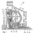
図1は、三方アッセンブリを備えた本発明のクラッチアッセンブリ100の部分横断面図である。三方アッセンブリとは、クラッチアッセンブリにおいて、3つの液体回路が使用されることを意味している。トルクコンバータ102は可撓性のディスク104に結合されている。さらに、このディスク104は駆動ユニット(図示せず)、たとえば原動機に結合されている。この駆動ユニットは入力トルクを可撓性のディスク104に伝達する。振動ダンパ106はコイルばね108を有していて、突起110を介してディスク104に結合されている。フランジ112は楔114に結合されている。さらに、この楔114はピストンまたは反応ディスク116に結合されている。以下、ピストンおよび反応ディスクという概念は同義的に使用され、トルクコンバータ内の液体圧に対する反応として運動させられる構造体を示している。ポンプクラッチ118とトルクコンバータクラッチ120とは、(楔114を介して)ピストン116に結合されている。幾つかの観点では、クラッチ120が、閉鎖されたピストンを有している。これによって、遠心的な押圧効果が十分に減少させられる。クラッチ118は入力トルクをピストン116を介してポンプ122に伝達する。クラッチ120はディスク124に結合されている。さらに、このディスク124はハブ126に結合されている。さらに、このハブ126は被駆動軸128に結合されている。クラッチ120は入力トルクを軸128に伝達する。
FIG. 1 is a partial cross-sectional view of a
アイドリング運転中には、液体通路もしくは液体チャンバ130(液体通路および液体チャンバという概念は、以下、同義的に使用される)における液体圧が通路131を介して増加させられ、液体通路132内で開口133を介して減少させられる。通路130内の高い圧力によって、ポンプ122が軸方向で駆動ユニットに向かって(図1で見て左方に)運動させられる。これによって、ディスク136がピストン116から離れる方向に運動させられ、ポンプクラッチ118が分離される。通路132内の低い圧力によって、ディスク138はクラッチ120から分離されたままとなる。したがって、両クラッチが分離されており、ポンプ122も軸128も被駆動トルクに結合されていない。これによって、アイドリング運転中には、駆動ユニットに作用する負荷が減少させられ、この駆動ユニットのエネルギ効率が改善される。
During idling operation, the liquid pressure in the liquid passage or liquid chamber 130 (the concept of liquid passage and liquid chamber is used interchangeably hereinafter) is increased through the
トルクコンバータ102の作動のためには、通路130内の圧力が増加させられる。これによって、ポンプ122が軸方向で変速機(図示せず)に向かって(図1で見て左方から右方に)運動させられる。この運動はクラッチ118の連結に繋がる。すなわち、ディスク136が左方から右方に運動させられ、ピストン116を連結する。図1には、このピストン116に取り付けられた摩擦材料140が示している。この摩擦材料140によって、ピストン116とディスク136とが内外で係合する。上述した内外係合によって、入力トルクがポンプ122に伝達される。しかし、明らかであるように、摩擦材料はディスク136に取り付けられてもよいし、ピストン116だけでなく、ディスク136にも取り付けられてよい。以下の説明では、摩擦材料を特定の構成で図示する。しかし、この場合、摩擦材料140の説明に関して、明らかであるように、別の構成も可能である。簡潔に述べるために、摩擦材料の取付けの前記論議は繰り返さない。クラッチ120は解除されたままである。これによって、軸128がポンプ122とタービン142との液体接続を介して駆動される。
For operation of the
連結のためには、通路132内の圧力が開口133を介して増加させられる。これによって、ディスク138が左方から右方に運動させられ、クラッチ120が連結される。連結されたクラッチ120はトルクを楔114からディスク124に伝達する。このディスク124はエネルギを、上述したように、軸128に伝達する。クラッチ118は連結されたままである。駆動ユニットから入力トルクを受け取るトルクコンバータの構成要素には、車両の慣性に基づき入力トルクに抗して作用する負荷も作用する。ポンプの分離時のトルクコンバータモードから連結モードへの変換時には、負荷が過度に急速に減少するようになっており、これによって、駆動ユニットが過回転する。しかし、クラッチ118がトルクコンバータモードから連結への変換時に連結されたままであると有利である。すなわち、ポンプの慣性モーメントが入力トルクを安定化させ、トルクの変動を減少させる。幾つかの観点では、駆動軸に伝達された入力トルクが安定化させられるやいなや、クラッチ118が解除される。この観点は、特にトルクコンバータ102が連結モードにおいて低い原動機回転数で作業する場合に有利である。低い回転数では、低周波の共振が生ぜしめられるようになっており、この共振がクラッチ118の解除によってシフトされるようになっている。チャンバ144内の圧力は全ての運転状態において高いままである。
For connection, the pressure in the
図1Aは、図1に示した突起およびばねの構成の斜視図である。 FIG. 1A is a perspective view of a configuration of a protrusion and a spring shown in FIG.
図1Bは、図1Aに示したB−B線に沿った部分横断面図である。図1、図1Aおよび図1Bから、以下のことが明らかである。図1Aおよび図1Bには、ばね108、突起110、フランジ112およびカバー146の構成が示してある。図1では、ばね108と突起110とが軸線148に対して、それぞれ半径方向のかつ軸方向の同一のレベルの内部に位置している。幾つかの観点では、ばね108と突起110とが、図1Bに示したように、相互に妨害されないように、接線方向に互いにずらされている。このずれによって、スペースをより良好に使用することができる。このことは、特にスペース問題が存在するトルクコンバータまたは振動ダンパにおいて有利である。
FIG. 1B is a partial cross-sectional view along the line BB shown in FIG. 1A. From FIG. 1, FIG. 1A and FIG. 1B, the following is clear. 1A and 1B show the configuration of the
図2は、三方アッセンブリと2つのクラッチとを備えた本発明のクラッチアッセンブリ200の部分横断面図である。数多くの観点では、各クラッチがトルクコンバータクラッチである。幾つかの観点では、一方のクラッチがトルクコンバータクラッチであり、他方のクラッチがポンプクラッチである。トルクコンバータ202は可撓性のディスク204に結合されている。さらに、このディスク204は駆動ユニット(図示せず)、たとえば原動機に結合されている。この駆動ユニットは入力トルクを可撓性のディスク204に伝達する。カバー206は突起208によってディスク204に結合されている。振動ダンパ210はディスク212とディスクもしくは中間カバー214とに結合されている。ポンプクラッチ216はディスク212に結合されている。さらに、このディスク212はダンパ210を介してディスク214に結合されている。このディスク214はポンプ220のハウジング218に結合されている。クラッチ216は入力トルクをポンプ220に伝達する。トルクコンバータクラッチ222はディスク214とディスク224とに結合されている。このディスク224はハブ226に結合されている。さらに、このハブ226は被駆動軸228に結合されている。クラッチ222は入力トルクを軸228に伝達する。
FIG. 2 is a partial cross-sectional view of a
アイドリング運転中には、全ての液体通路230,232,234内に高い液体圧が維持される。この高い圧力によって、クラッチ216,222が解除される。したがって、ポンプ220も軸228も出力トルクに結合されていない。これによって、アイドリング運転中には、駆動ユニットに加えられる負荷と、この駆動ユニットの燃料消費量とが減少させられる。
During the idling operation, a high liquid pressure is maintained in all the
トルクコンバータ202が作動するように、ポンプ220内にキャビテーションが生ぜしめられることなしに、通路230内の圧力が可能な限り十分に減少させられる。通路232内の圧力は可能な限り高く保持される。通路234内の圧力は通路230内の圧力よりも高く保持されるものの、通路232内の圧力よりは低く保持される。圧力のこの構成によって、ディスク212がカバー206の方向に運動させられ、クラッチ216が連結される。図2には、ディスク212に設けられた摩擦材料236が示してある。この摩擦材料236はディスク212とカバー206との間の連結に繋がる。上述した連結によって、入力トルクがポンプ220に伝達される。クラッチ222は解除されたままである。したがって、軸228がポンプ220とタービン238との液体接続によって駆動される。
In order for the
液体通路240は、切り欠かれた中間ディスク242を介して液体通路234への液体接続を形成する。連結のためには、通路240内の圧力が最小値に減少させられる。これによって、ディスク214,224が互いに近づく方向に運動させられる。この運動によって、クラッチ222が連結する。連結されたクラッチ222は、上述したように、トルクをディスク214から軸228に伝達する。クラッチ216は連結されたままである。ディスク224に図示した摩擦材料244によって、ディスク214,224が内外で係合する。トルクコンバータに結合された駆動ユニットは、上述したように、トルクコンバータモードから連結モードへの変換時に望ましくない形式で過回転し得る。しかし、クラッチ216は、トルクコンバータモードから連結モードへの変換の間、連結されたままである。
The
図2Aは、図2に示した切り欠かれた中間ディスク242の斜視図である。図2および図2Aから、以下のことが明らかである。中間ディスク242は溝246を有している。この溝246は液体通路234,240の間の液体接続を形成する。幾つかの観点(図示せず)では、中間ディスクは切り欠かれていない。その代わりに、通路232,240の間の液体接続が形成されるように、ディスク214がスリットを備えている(図示せず)。この場合、圧力はアイドリング運転モードにおいて全ての通路内で高いままである。トルクコンバータモードに移行するためには、クラッチ216が連結するように、通路232内の圧力が減少させられる。連結モードへの移行のためには、通路232内の圧力が、通路230内の圧力と通路234内の圧力との間の平均的な値に減少させられる。この構成によって、キャビテーションが生ぜしめられないように、通路230内の圧力を十分に高く保持することができる。
2A is a perspective view of the cut-out
図3は、三方アッセンブリとランチェスタダンパとを備えた本発明のクラッチアッセンブリ300の部分横断面図である。トルクコンバータ302は可撓性のディスク304に結合されている。さらに、このディスク304は駆動ユニット(図示せず)、たとえば原動機に結合されている。この駆動ユニットは入力トルクを可撓性のディスク304に伝達する。カバー306は、溶接箇所を介してねじ308でディスク304に結合されている。トーションダンパ310はフランジ312を有している。このフランジ312は楔314を介してカバー306に結合されている。ポンプクラッチ316はトルクコンバータハウジング318とポンプハウジング320とに結合されている。クラッチ316は入力トルクをポンプ322に伝達する。トルクコンバータクラッチ324は、ピストン326と、ディスク328と、ディスク329とに結合されている。このディスク329はダンパ310に結合されている。ディスク326はタービンハウジング330に結合されている。さらに、このタービンハウジング330はハブ332に結合されている。このハブ332は被駆動軸334に結合されている。クラッチ324は入力トルクを軸334に伝達する。幾つかの観点では、クラッチ324が、閉鎖されたピストンを備えたクラッチである。この閉鎖されたピストンを備えたクラッチは、遠心的な押圧効果にほとんど見舞われていない。
FIG. 3 is a partial cross-sectional view of a
アイドリング運転中には、通路336,338内の液体圧が増加させられ、通路340内の圧力が低く保持される。これらの圧力によって、クラッチ316,324は解除される。したがって、入力トルクはポンプ322にも軸334にも加えられない。これによって、アイドリング運転モードでは、駆動装置に加えられる負荷と、エネルギ消費量とが減少させられる。
During the idling operation, the liquid pressure in the
トルクコンバータ302を作動させるためには、通路338,340内の圧力が可能な限り低く保持され、通路336内の圧力が増加させられる。この圧力構成によって、ポンプ322が軸方向で変速機(図示せず)に向かって(図3で見て左方から右方に)運動させられ、クラッチ316が連結する。図3でハウジング320に示した摩擦材料342が、ハウジング318,320の間の連結を生ぜしめる。上述した連結によって、入力トルクがポンプ332に伝達される。クラッチ324は解除されたままである。これによって、軸334がポンプ322とタービン344との液体接続によって駆動される。
In order to operate the
連結状態に到達するためには、通路336内の圧力が減少させられ、通路338,340内の圧力が増加させられる。通路340内の圧力は通路338内の圧力を超えて増加させられる。これらの圧力によって、クラッチ324が連結される。チャンバ336内の圧力は、トルクコンバータ内のキャビテーションを回避するために必要となる最小圧である。チャンバ338内の圧力は、十分な液体冷却を保証するために必要となる最小圧である。チャンバ340内の圧力は、クラッチ324の所要の出力を達成するために必要になる最小圧である。連結されたクラッチ324は、上述したように、トルクをディスク329から軸334に伝達する。ディスク329に図示した摩擦材料346は、ディスク328とディスク329との間ならびにディスク329とピストン326との間の連結を生ぜしめる。
In order to reach the coupled state, the pressure in the
デュアルマストルクコンバータは、力伝達におけるトルク変動を減少させるために使用することができる。したがって、ダンパ348がトルクコンバータ302のコアリング350に取り付けられていて、連結モードの間、ポンプ322からタービン344への慣性モーメントの伝達のために働く。幾つかの観点では、ダンパはランチェスタダンパである。コンバータモードでは、トルクコンバータ302におけるトルクが、ダンパ348の、許容範囲内で最高のトルクを上回り、これによって、トルクコンバータ302がスリップし始める。しかし、ダンパ348の、許容範囲内で最高のトルクは比較的低いので、このスリップはトルクコンバータ302の出力に著しく影響を与える。トルクコンバータ302によって伝達されるトルク変動が僅か(ダンパ348の、許容範囲内で最高のトルクよりも僅か)である場合の連結モードでは、ダンパ348がポンプをタービンに連結し、したがって、デュアルマストルクコンバータの機能性を発生させる。
A dual mass torque converter can be used to reduce torque fluctuations in force transmission. Accordingly, a
図4は、二方アッセンブリを備えた本発明のクラッチアッセンブリ400の部分横断面図である。二方アッセンブリとは、2つの液体回路が使用されることを意味している。トルクコンバータ402は可撓性のディスク404に結合されている。さらに、このディスク404は(部分的に示した)駆動ユニット405、たとえば原動機に結合されている。この駆動ユニットは入力トルクを可撓性のディスク404に伝達する。カバー406は突起408を介してディスク404に結合されている。トルクダンパ410はカバー406とピストン412とに結合されている。ポンプクラッチ414はピストン412とディスク416とに結合されている。このディスク416はポンプ420のハウジング418に結合されている。クラッチ414は入力トルクをポンプ420に伝達する。トルクコンバータクラッチ422はディスク416とタービン426のハウジング424とに結合されている。このハウジング424はハブ428に結合されている。さらに、このハブ428は被駆動軸430に結合されている。クラッチ414,422は入力トルクを軸430に伝達する。
FIG. 4 is a partial cross-sectional view of a
アイドリング運転モードでは、液体チャンバ432内の液体圧は高いままであり、チャンバ434内の圧力は低いままである。これらの圧力によって、ポンプ420が軸方向で変速機(図示せず)に向かって(図4で見て左方から右方に)運動させられ、クラッチ414,422が解除する。これによって、入力トルクはポンプ420にも軸430にも加えられない。この理由から、アイドリング運転モードでは、駆動ユニットに加えられる負荷ひいては駆動ユニットのエネルギ消費量が減少させられている。アイドリング運転モードでは、ダイヤフラムばね436がディスク412を軸方向で変速機に向かって押圧する。
In the idling mode of operation, the liquid pressure in the
トルクコンバータ402を作動させるためには、チャンバ432内の圧力が減少させられ、チャンバ434内の圧力が平均的な値にもたらされる。これによって、ポンプ420が軸方向で駆動ユニットに向かって(図4で見て右方から左方に)運動させられ、クラッチ414が連結する。圧力差によってポンプ420に加えられる軸方向の力は、ばね436を介してディスク412によって受け止められる。ばねは、クラッチ414が連結することができるまで撓むものの、クラッチ422が連結することができるまでは撓まない。図4に示した、ディスク440,442に設けられた摩擦材料438は、ディスク412,416を互いに連結する。上述した連結によって、入力トルクがポンプ420に伝達される。クラッチ422は解除されたままである。したがって、軸430がポンプ420とタービン426との間の液体接続によって駆動される。
In order to operate the
連結モードへの移行のためには、通路434内の圧力が最大値にまで増加させられ、これによって、ポンプ420が軸方向で引き続き駆動ユニットに向かって運動させられる。圧力差に基づきポンプ420に加えられる一層強い力は、クラッチ414によってディスク412に伝達され、ばね436を引き続き撓ませる。これによって、ディスク412が引き続き駆動ユニットの方向に運動させられ、クラッチ422を連結する。連結されたクラッチ422は、上述したように、トルクをディスク412から軸430に伝達する。クラッチ414は連結されたままである。ディスク416に設けられた摩擦材料446はディスク416,448を互いに連結する。すでに上述したように、トルクコンバータに結合された駆動ユニットは、トルクコンバータモードから連結モードへの変換時に望ましくない形式で過回転し得る。しかし、トルクコンバータモードから連結モードへの変換時には、ハウジング406がハウジング408に結合されたままであり、慣性モーメントをポンプ420からハウジング424に伝達する。
For the transition to the connected mode, the pressure in the
図5は、2つの入力体を備えた変速機に結合されたトルクコンバータに用いられる本発明のクラッチアッセンブリ500の部分横断面図である。2つの入力体を備えた変速機とは、力伝達手段がマニュアル式のシフトトランスミッション、つまり、手動変速機から成っていることを意味している。この手動変速機は第1の駆動軸502と第2の駆動軸504とを有している。両駆動軸502,504は奇数段の歯車(図示せず)もしくは偶数段の歯車(図示せず)に結合されている。駆動軸502,504は互いに同心的である。以下、駆動軸502,504を奇数段の変速機駆動軸もしくは偶数段の変速機駆動軸と呼ぶ。「奇数段の変速機駆動軸」とは、第1の駆動軸が、力伝達手段に設けられた奇数段の歯車、すなわち、1速、3速、5速等の歯車に結合されていることを意味している。さらに、「偶数段の変速機駆動軸」とは、第2の駆動軸が、力伝達手段に設けられた偶数段の歯車、すなわち、2速、4速、6速等の歯車に結合されていることを意味している。しかし、明らかであるように、奇数段の変速機駆動軸と偶数段の変速機駆動軸とは、力伝達手段に配置された多数の歯車に結合されていてよい。
FIG. 5 is a partial cross-sectional view of a
本発明500は、トルクコンバータ505を奇数段の変速機駆動軸502に連結するための手段を有している。トルクコンバータ505は、一般的に、ポンプ506と、タービン508と、ポンプ506とタービン508との間に配置されたステータ510と、ディスク512とを有している。このディスク512はフランジディスク514と可撓性のディスク516との間に配置されている。このディスク516は被駆動軸(図示せず)を介して駆動ユニット(図示せず)、たとえば内燃機関に結合されている。フランジディスク514は振動ダンパ518に結合されている。可撓性のディスク516はディスク512に結合されている。さらに、このディスク512はトルクコンバータのハウジング519に結合されており、これによって、このハウジングが可撓性のディスク516と一緒に回転させられるようになっている。駆動ユニットから到来した入力トルクは、可撓性のディスク516を介してディスク512に伝達され、引き続き、振動ダンパ518に伝達され、その後、フランジディスク514に伝達される。このフランジディスク514は奇数段の変速機駆動軸502に取り付けられていて、シールリング520によってシールされて、奇数段の変速機駆動軸502に結合されている。
The
アッセンブリ500はタービンクラッチ521と摩擦クラッチ522,524を有している。しかし、明らかであるように、タービンクラッチ521も同じく摩擦クラッチとして知られている。摩擦クラッチ522はフランジディスク514とピストン526との間に配置されている。クラッチ522は、機能的に、フランジディスク514とピストン526とを連結し、したがって、フランジディスク514によって受け止められた入力トルクをフランジディスク514からピストン526を介して奇数段の変速機駆動軸502に伝達するように配置されている。ピストンはタービンハウジング528とフランジディスク514との間に配置されている。摩擦クラッチ524はピストン530とフランジディスク514との間に配置されている。クラッチ524は、機能的に、フランジディスク514をピストン530に連結し、したがって、フランジディスク514によって受け止められた入力トルクをフランジディスク514からピストン530を介して偶数段の変速機駆動軸504に伝達するように配置されている。ピストン530は偶数段の変速機駆動軸504に取り付けられていて、楔531によって偶数段の変速機駆動軸504に拘束されている。ピストン530も同じく、シールリング(図示せず)によってシールされて、偶数段の変速機駆動軸504に結合されている。
The
幾つかの観点では、ピストン526をタービンに連結しかつタービンから解除するための手段が、タービンクラッチ521を有している。ピストン526は奇数段の変速機駆動軸502に取り付けられていて、楔533によって奇数段の変速機駆動軸502に拘束されている。以下に、偶数段の変速機駆動軸504の内部に設けられた管路534、奇数段の変速機駆動軸502と偶数段の変速機駆動軸504との間に設けられた管路536、ステータ軸540と奇数段の変速機駆動軸502との間に設けられた管路538および/またはステータ軸540とハウジング519との間に設けられた管路542を通して供給される圧力下にある媒体のハイドロリック圧の、制御された変化によって、どのようにして摩擦クラッチ522,524とタービンクラッチ521とが連結されるのかを詳しく説明する。管路534は流入通路である。「流入通路」とは、媒体が変速機パン(図示せず)から管路534に流れることを意味している。管路534,536,538,542は相応の液体チャンバ544,546,548,550を有している。管路534内の圧力と、相応のチャンバ544内の圧力とは常に高い。管路536,538,542は流出通路である。「流出通路」とは、媒体が管路536,538,542を通って再び変速機パンに戻ることを意味している。管路536,538,542内の圧力は弁(図示せず)によって調整される。圧縮された媒体として、たとえば高圧オイルが使用されてよい。しかし、明らかであるように、別の高圧媒体が使用されてもよく、この変更は本発明の精神に相当していて、その適用範囲内に位置している。ピストン526と、ピストン526と、ディスク530とには、摩擦材料552a;552b;552cが取り付けられている。
In some aspects, the means for connecting and releasing the
図6Aには、図5の本発明のクラッチアッセンブリ500が示してある。このクラッチアッセンブリ500では、タービン508がタービンクラッチ521によって連結されている。このクラッチが解除されている場合のアイドリング運転中には、管路536,538,542の3つの流出弁が全て閉鎖されており、これによって、オイルがトルクコンバータ505から流出することができない。タービンクラッチをトルクコンバータモードでのクリープギヤ段および発進に対して連結するためには、車両のブレーキペダルが解放され(図示せず)、管路542に対する弁が開放され、これによって、オイルがパン内に流出することができる。したがって、管路542内の圧力と、相応の液体チャンバ550内の圧力とが低くなる。管路536,538の弁は閉鎖されたままであり、これによって、相応の液体チャンバ546,548内の圧力は高いままである。管路534内の圧力と、相応の液体チャンバ544内の圧力とは常に高いままである。明らかであるように、トルクコンバータモードでオイルが冷却のために約2〜3l/minの通流量で通流することができるように、ピストン526は切り欠かれている。管路534、536,538内の高い圧力によって、ピストン526が軸方向でタービン508に向かって移動させられ、タービンクラッチ521がタービンハウジング528を介してタービン508に結合される。したがって、タービン508から到来したトルクを増加させるクリープトルクがゆっくりと増加し、車両がクリープし始め、発進し始める。「クリープおよび発進」とは、車両が静止から運動させられることを意味している。当業者に明らかであるように、トルクコンバータ505はトルクを増幅させる。このトルク増幅は、クリープギヤ段、発進、山道での発進およびストールの場合に使用される。原動機回転数とタービン回転数との比が、規定された値を上回ると、奇数段の変速機駆動軸502に結合された摩擦クラッチ522が連結する。幾つかの観点では、設定された比が0.5にほぼ等しい。すなわち、タービン508が、力伝達手段の回転数と、駆動ユニットの回転数で回転するポンプ506の回転数の半分の回転数とで回転させられる。トルクコンバータ505はトルクを増幅するので、発進時の静穏なかつ迅速な加速のためには、より低い第1の変速比が必要になる。さらに、トルク増幅によって、力伝達において必要となる中間間隔が減少させられ、これによって、力伝達手段の重量およびコストも減少させることができる。
FIG. 6A shows the
図6Bには、図5の本発明のクラッチアッセンブリ500が示してある。このクラッチアッセンブリ500では、タービン508のタービンクラッチ521が解除されており、クラッチ552が連結されている。タービンクラッチ521がまだ連結されている間に摩擦クラッチ522を連結するためには、摩擦クラッチ522が発進過程の終了時に完全に連結されているまで、摩擦クラッチ522のトルクがゆっくり増加させられる。「ゆっくり増加させられる」とは、摩擦クラッチ522がタービンの回転数に到達するまで、トルクが摩擦クラッチ522で少なくとも1.5sの期間にわたって増加させられることを意味している。この時点でタービンクラッチ521は解除されている。より正確に言うならば、摩擦クラッチ522の連結のためには、管路534の弁が閉鎖されたままであり、したがって、管路534内の圧力が高いままである。管路538,542の弁が開放され、これによって、オイルがパン内に流出し、管路538,542内の圧力と、相応の液体チャンバ548;550内に圧力とが低くなる。ピストン526が軸方向でタービン508から離れる方向に運動させられ、ピストン526とフランジディスク514とが内外で係合する。したがって、クラッチ522が連結されている場合には、トルクが奇数段の変速機駆動軸502に伝達される。この奇数段の変速機駆動軸502における第1速(図示せず)と、偶数段の変速機駆動軸504における第2速(図示せず)との間の変速時の同期化は摩擦クラッチ522;524によって、変速が自動変速機に匹敵し得るように行われる。幾つかの観点では、タービンクラッチ521が、タービンハウジング528に取り付けられた、遠心的に制御される弁(図示せず)によって連結される。幾つかの観点では、タービンクラッチ521が、管路538に接続された弁(図示せず)によって連結される。
FIG. 6B shows the
摩擦クラッチ524を連結しかつクラッチ522を解除するためには、管路538および管路542に対する弁が閉鎖され、これによって、相応の液体チャンバ548;550内に高い圧力が形成される。管路536の弁が開放しており、これによって、液体が変速機パン(図示せず)内に流出し、管路548内の圧力が低くなる。これによって、ピストンディスク530が軸方向でフランジディスク514に向かって移動させられ、これによって、ピストンディスク530とフランジディスク514とが内外で係合する。したがって、クラッチ524が連結されている場合には、トルクが偶数段の変速機駆動軸504に伝達される。
To connect the
クラッチ522を再度連結しかつクラッチ524を解除するためには、管路536,542の弁が閉鎖され、これによって、この管路536,542内の圧力と、相応の液体チャンバ546,550内の圧力とが高くなる。管路538の弁は開放しており、これによって、液体が変速機パン内に流出し、管路538内の圧力と液体チャンバ548内の圧力とが低くなる。
In order to re-engage the clutch 522 and disengage the clutch 524, the valve in
当業者にやはり明らかであるように、力伝達手段において各駆動軸に摩擦クラッチと異なるクラッチ、たとえば多板クラッチおよび閉鎖されたピストンを備えたクラッチと、別個のダンパとが使用されてよく、この変更は本発明の精神に相当していて、その適用範囲内に位置している。同じく明らかであるように、トルクコンバータのカバー内にデュアルマスフライホイールダンパが組み付けられてよい。さらに、慣用の可撓性のディスクが使用されてよく、したがって、製造コストを減少させることができる。 As will also be apparent to those skilled in the art, a clutch different from the friction clutch on each drive shaft in the force transmission means, for example a clutch with a multi-plate clutch and a closed piston, and a separate damper may be used. Modifications correspond to the spirit of the invention and are within its scope. As will also be apparent, a dual mass flywheel damper may be assembled in the cover of the torque converter. In addition, conventional flexible discs may be used, thus reducing manufacturing costs.
図7Aには、本発明のクラッチアッセンブリ500を備えた車両の発進時の原動機回転数曲線が示してある。発進の最初の3秒の間、クラッチアッセンブリ500では、クラッチアッセンブリなしのトルクコンバータに連結されている力伝達手段よりも低い原動機回転数が必要になる。クラッチアッセンブリ500には、単純なクラッチシステムに連結された力伝達手段とほぼ同じ原動機回転数が必要となる。たとえば、クラッチアッセンブリ500および単純なクラッチシステムの場合の原動機回転数が2秒後には約1300min−1であるのに対して、クラッチアッセンブリなしのトルクコンバータには、約1600min−1の原動機回転数が必要となる。
FIG. 7A shows a prime mover rotational speed curve when the vehicle including the
図7Bには、本発明のクラッチアッセンブリ500を備えた車両の発進時のトルク曲線が示してある。クラッチアッセンブリなしのトルクコンバータを備えた力伝達手段と異なり、クラッチアッセンブリ500では、より低い原動機回転数が必要になるにもかかわらず、クラッチアッセンブリなしのトルクコンバータよりも大きなトルクが提供される。たとえば、クラッチアッセンブリ500が2秒後に約90Nmのトルクを供給するのに対して、クラッチアッセンブリなしのトルクコンバータは約80Nmのトルクしか供給しない。湿式クラッチを含む摩擦発進システムと異なり、2つの入力体を備えた手動変速機に用いられるクラッチアッセンブリを備えたトルクコンバータの使用時には、トルクが増幅させられるので、山道での発進に対して限界は存在しない。明らかであるように、発進特性値、たとえば必要とされる原動機回転数の減少およびクラッチアッセンブリ500によって提供されるトルクの増加は、あらゆる温度および条件で再現可能となる。
FIG. 7B shows a torque curve at the time of start of the vehicle provided with the
図7Cは、本発明のクラッチアッセンブリ500に相俟った車両の発進時の燃料消費量線図である。この燃料消費量線図には、クラッチアッセンブリ500による発進に対する曲線が、単純なクラッチによる発進およびクラッチアッセンブリなしのトルクコンバータによる発進と比較して示してある。曲線は、発進時のクラッチアッセンブリ500の効率が、単純なクラッチによる発進時およびクラッチアッセンブリなしのトルクコンバータによる発進時よりも著しく高いことを示している。このことは、EPAによる標準化された都市走行運転において約1%の全燃料節約に繋がる。明らかであるように、車両がアイドリング運転に位置している場合(アイドリング運転解除モード)にクラッチアッセンブリ500を完全に原動機から分離することができ、したがって、トルクコンバータの使用時に一般的に生ぜしめられる出力損失が回避される。
FIG. 7C is a fuel consumption diagram at the start of the vehicle in combination with the
クラッチシステムがトルクコンバータハウジングの内部に位置する、2つの入力体を備えた手動変速機に用いられるクラッチアッセンブリ500の使用時の更なる利点は、トルクコンバータの寸法を通常のトルクコンバータに比べて減少させることができることにある。なぜならば、摩擦クラッチ522が、いずれにせよ、許容範囲内で最高のトルクを増加させるからである。さらに、質量と慣性モーメントとが減少させられる。トルクコンバータのカバーが主慣性モーメントを供給し、これによって、湿式体積または乾式体積が不要になる。さらに、鋼が熱吸収のために働き、材料が可能な限り最良に使用される。同じくクラッチが著しく縮小されている。なぜならば、トルクコンバータが、クラッチのサイズに最も高い要求を課す発進およびストールのプロセスを克服するからである。
A further advantage when using the
したがって、本発明の課題は、当業者が、特許請求の範囲の適用範囲内に位置する、本発明における変更および変化を容易に行うことができるにもかかわらず、有効に解決される。 Therefore, the problems of the present invention are effectively solved even though those skilled in the art can easily make changes and changes in the present invention which are within the scope of the claims.
100 クラッチアッセンブリ、 102 トルクコンバータ、 104 ディスク、 106 振動ダンパ、 108 コイルばね、 110 突起、 112 フランジ、 114 楔、 116 ピストン、 118 ポンプクラッチ、 120 トルクコンバータクラッチ、 122 ポンプ、 124 ディスク、 126 ハブ、 128 被駆動軸、 130 液体通路、 131 液体通路、 132 液体通路、 133 開口、 136 ディスク、 138 ディスク、 140 摩擦材料、 142 タービン、 144 チャンバ、 146 カバー、 148 軸線、 200 クラッチアッセンブリ、 202 トルクコンバータ、 204 ディスク、 206 カバー、 208 突起、 210 振動ダンパ、 212 ディスク、 214 ディスク、 216 ポンプクラッチ、 218 ハウジング、 220 ポンプ、 222 トルクコンバータクラッチ、 224 ディスク、 226 ハブ、 228 被駆動軸、 230 液体通路、 232 液体通路、 234 液体通路、 236 摩擦材料、 238 タービン、 240 液体通路、 242 中間ディスク、 244 摩擦材料、 246 溝、 300 クラッチアッセンブリ、 302 トルクコンバータ、 304 ディスク、 306 カバー、 308 ねじ、 310 トーションダンパ、 312 フランジ、 314 楔、 316 ポンプクラッチ、 318 トルクコンバータハウジング、 320 ポンプハウジング、 322 ポンプ、 324 トルクコンバータクラッチ、 326 ピストン、 328 ディスク、 329 ディスク、 330 タービンハウジング、 332 ハブ、 334 被駆動軸、 336 通路、 338 通路、 340 通路、 342 摩擦材料、 344 タービン、 346 摩擦材料、 348 ダンパ、 350 コアリング、 400 クラッチアッセンブリ、 402 トルクコンバータ、 404 ディスク、 405 駆動ユニット、 406 カバー、 408 突起、 410 トルクダンパ、 412 ピストン、 414 ポンプクラッチ、 416 ディスク、 418 ハウジング、 420 ポンプ、 422 トルクコンバータクラッチ、 424 ハウジング、 426 タービン、 428 ハブ、 430 被駆動軸、 432 液体チャンバ、 434 液体チャンバ、 436 ダイヤフラムばね、 438 摩擦材料、 440 ディスク、 442 ディスク、 446 摩擦材料、 448 ディスク、 500 クラッチアッセンブリ、 502 駆動軸、 504 駆動軸、 505 トルクコンバータ、 506 ポンプ、 508 タービン、 510 ステータ、 512 ディスク、 514 フランジディスク、 516 ディスク、 518 振動ダンパ、 519 ハウジング、 520 シールリング、 521 タービンクラッチ、 522 摩擦クラッチ、 524 摩擦クラッチ、 526 ピストン、 528 タービンハウジング、 530 ピストン、 531 楔、 533 楔、 534 管路、 536 管路、 538 管路、 540 ステータ軸、 542 管路、 544 液体チャンバ、 546 液体チャンバ、 548 液体チャンバ、 550 液体チャンバ、 552a 摩擦材料、 552b 摩擦材料、 552c 摩擦材料 100 clutch assembly, 102 torque converter, 104 disc, 106 vibration damper, 108 coil spring, 110 protrusion, 112 flange, 114 wedge, 116 piston, 118 pump clutch, 120 torque converter clutch, 122 pump, 124 disc, 126 hub, 128 Driven shaft, 130 liquid passage, 131 liquid passage, 132 liquid passage, 133 opening, 136 disc, 138 disc, 140 friction material, 142 turbine, 144 chamber, 146 cover, 148 axis, 200 clutch assembly, 202 torque converter, 204 Disc, 206 Cover, 208 Projection, 210 Vibration damper, 212 Disc, 214 Disc 216 pump clutch, 218 housing, 220 pump, 222 torque converter clutch, 224 disc, 226 hub, 228 driven shaft, 230 liquid passage, 232 liquid passage, 234 liquid passage, 236 friction material, 238 turbine, 240 liquid passage, 242 intermediate disc, 244 friction material, 246 groove, 300 clutch assembly, 302 torque converter, 304 disc, 306 cover, 308 screw, 310 torsion damper, 312 flange, 314 wedge, 316 pump clutch, 318 torque converter housing, 320 pump housing , 322 pump, 324 torque converter clutch, 326 piston, 328 disc, 329 Disc, 330 turbine housing, 332 hub, 334 driven shaft, 336 passage, 338 passage, 340 passage, 342 friction material, 344 turbine, 346 friction material, 348 damper, 350 core ring, 400 clutch assembly, 402 torque converter, 404 Disc, 405 drive unit, 406 cover, 408 protrusion, 410 torque damper, 412 piston, 414 pump clutch, 416 disc, 418 housing, 420 pump, 422 torque converter clutch, 424 housing, 426 turbine, 428 hub, 430 driven shaft, 432 liquid chamber, 434 liquid chamber, 436 diaphragm spring, 438 friction material, 44 Disc, 442 Disc, 446 Friction Material, 448 Disc, 500 Clutch Assembly, 502 Drive Shaft, 504 Drive Shaft, 505 Torque Converter, 506 Pump, 508 Turbine, 510 Stator, 512 Disc, 514 Flange Disc, 516 Disc, 518 Vibration Damper , 519 Housing, 520 Seal ring, 521 Turbine clutch, 522 Friction clutch, 524 Friction clutch, 526 Piston, 528 Turbine housing, 530 Piston, 531 Wedge, 533 Wedge, 534 Pipe line, 536 Pipe line, 538 Pipe line, 540 Stator Shaft, 542 conduit, 544 liquid chamber, 546 liquid chamber, 548 liquid chamber, 550 liquid chamber Chamber, 552a friction material, 552b friction material, 552c friction material
Claims (30)
ポンプクラッチを有しており、該ポンプクラッチが、機能的に、当該トルクコンバータの入力トルクを、当該トルクコンバータに設けられたポンプに伝達するように配置されており、
トルクコンバータクラッチを有しており、該トルクコンバータクラッチが、機能的に、入力トルクを当該トルクコンバータの被駆動軸に伝達するように配置されており、入力トルクが軸に伝達される場合に、入力トルクがさらにポンプに加えられるように、ポンプクラッチが配置されていることを特徴とする、トルクコンバータ。 In the torque converter, the torque converter
A pump clutch, and the pump clutch is functionally arranged to transmit the input torque of the torque converter to a pump provided in the torque converter;
A torque converter clutch, wherein the torque converter clutch is functionally arranged to transmit the input torque to the driven shaft of the torque converter, and the input torque is transmitted to the shaft; A torque converter, wherein a pump clutch is arranged so that input torque is further applied to the pump.
少なくとも1つの振動減衰手段を有しており、該振動減衰手段が、機能的に、入力トルクに結合されており、該入力トルクがポンプに伝達される場合に、入力トルクが少なくとも1つの振動減衰手段を通して伝達されるように、少なくとも1つの振動減衰手段が、当該トルクコンバータに配置されている、請求項1記載のトルクコンバータ。 The torque converter further includes
At least one vibration damping means, which is functionally coupled to the input torque and when the input torque is transmitted to the pump, the input torque is at least one vibration damping. The torque converter according to claim 1, wherein at least one vibration damping means is arranged in the torque converter for transmission through the means.
振動減衰手段と、ポンプクラッチと、トルクコンバータクラッチとに機能的に結合される反応ディスクを有しており、ポンプクラッチとトルクコンバータクラッチとが、反応ディスクをポンプもしくは軸に連結するように配置されている、請求項3記載のトルクコンバータ。 The torque converter further includes
Having a reaction disk functionally coupled to the vibration damping means, the pump clutch, and the torque converter clutch, the pump clutch and the torque converter clutch being arranged to connect the reaction disk to the pump or shaft; The torque converter according to claim 3.
少なくとも1つの突起を有しており、該突起が、少なくとも1つの振動減衰手段を可撓性のディスクに結合しており、
少なくとも1つの振動減衰手段が、さらに、少なくとも1つのばねを有しており、少なくとも1つの突起と、少なくとも1つのばねとが、半径方向でそれぞれ同一のレベルに延びていて、軸方向で当該トルクコンバータの長手方向軸線に方向付けられており、少なくとも1つの突起と、少なくとも1つのばねとが、軸線に対して接線方向にずらされている、請求項4記載のトルクコンバータ。 The torque converter further includes
At least one protrusion, the protrusion coupling at least one vibration damping means to the flexible disk;
The at least one vibration damping means further includes at least one spring, and the at least one protrusion and the at least one spring extend at the same level in the radial direction, and the torque in the axial direction. The torque converter of claim 4, wherein the torque converter is oriented in a longitudinal axis of the converter and the at least one protrusion and the at least one spring are offset tangentially to the axis.
第1の液体チャンバと第2の液体チャンバとを有しており、両液体チャンバが、ポンプクラッチもしくはトルクコンバータクラッチに接続されるようになっており、
切り欠かれた中間ディスクを有しており、該中間ディスクが、第1のチャンバと第2のチャンバとの間に位置していて、機能的に、第1のチャンバと第2のチャンバとの間での液体交換を可能にするように配置されている、請求項9記載のトルクコンバータ。 The torque converter further includes
A first liquid chamber and a second liquid chamber, both liquid chambers being connected to a pump clutch or a torque converter clutch;
A notched intermediate disk, the intermediate disk being located between the first chamber and the second chamber and functionally having a first chamber and a second chamber; The torque converter of claim 9, wherein the torque converter is arranged to allow liquid exchange between them.
第3の液体チャンバと第4の液体チャンバとを有しており、両液体チャンバが、ポンプクラッチもしくはトルクコンバータクラッチに接続されるようになっており、
中間ディスクを有しており、該中間ディスクが、第3のチャンバと第4のチャンバとの間に位置していて、機能的に、第3のチャンバと第4のチャンバとの間での液体交換を可能にするように配置されている、請求項9記載のトルクコンバータ。 The torque converter further includes
A third liquid chamber and a fourth liquid chamber, both liquid chambers being connected to a pump clutch or a torque converter clutch;
Having an intermediate disk, the intermediate disk being located between the third chamber and the fourth chamber, functionally liquid between the third chamber and the fourth chamber; The torque converter of claim 9, wherein the torque converter is arranged to allow replacement.
当該トルクコンバータに設けられたポンプから慣性モーメントを伝達するための少なくとも1つの手段を有しており、
トルクコンバータクラッチを有しており、該トルクコンバータクラッチが、機能的に、当該トルクコンバータに対する入力トルクを当該トルクコンバータの被駆動軸に伝達するように配置されており、入力トルクが軸に伝達される場合に、前記手段が、慣性モーメントを伝達するように配置されていることを特徴とする、トルクコンバータ。 In the torque converter, the torque converter
Having at least one means for transmitting a moment of inertia from a pump provided in the torque converter;
A torque converter clutch, and the torque converter clutch is functionally arranged to transmit the input torque to the torque converter to the driven shaft of the torque converter, and the input torque is transmitted to the shaft. The torque converter is arranged to transmit a moment of inertia.
トルクコンバータに対する入力トルクをトルクコンバータのポンプに伝達し;
入力トルクをトルクコンバータの被駆動軸に伝達する一方で、入力トルクをさらにポンプに伝達する:
を有していることを特徴とする、トルクコンバータに対する入力トルクを慣性抵抗に重畳するための方法。 In a method for superimposing an input torque to a torque converter on an inertial resistance, the method comprises the following steps:
Transmit the input torque to the torque converter to the torque converter pump;
While transmitting the input torque to the driven shaft of the torque converter, the input torque is further transmitted to the pump:
A method for superimposing an input torque to a torque converter on an inertial resistance.
入力トルクをポンプへの到達前に減衰する:
を有している、請求項15記載の方法。 The method further comprises the following steps:
Decrease input torque before reaching pump:
16. The method of claim 15, comprising:
入力トルクの減衰が、さらに、
半径方向でそれぞれ同一のレベルへの少なくとも1つの突起と少なくとも1つのばねとの設置および軸方向でトルクコンバータの長手方向軸線への方向付け;
接線方向で少なくとも1つの突起と少なくとも1つのばねとの相対的なずらし:
を包括している、請求項16記載の方法。 The torque converter further comprises at least one protrusion coupled to the at least one spring and a longitudinal axis;
Input torque attenuation
Installation of at least one protrusion and at least one spring, each at the same level in the radial direction and directing in the axial direction to the longitudinal axis of the torque converter;
Relative displacement of at least one protrusion and at least one spring in the tangential direction:
The method of claim 16, comprising:
トルクコンバータを有しており;
2つの入力体を備えた手動変速機に対する第1の駆動軸を有しており;
トルクコンバータと第1の駆動軸とを連結するための手段を有していることを特徴とする、トルク伝達のための装置。 In the device for torque transmission, the device is
Has a torque converter;
A first drive shaft for a manual transmission with two inputs;
A device for torque transmission, characterized by comprising means for connecting the torque converter and the first drive shaft.
システムに配置されたトルクコンバータにトルクを発生させ;
2つの入力体を備えたシステムの手動変速機の第1の駆動軸にトルクを伝達する:
を有していることを特徴とする、2つの入力体を備えた手動変速機システムに対するトルクを増加させるための方法。 In a method for increasing torque for a manual transmission system with two inputs, the method comprises the following steps:
Generate torque in a torque converter located in the system;
Torque is transmitted to the first drive shaft of the manual transmission of the system with two inputs:
A method for increasing torque for a manual transmission system with two inputs.
当該方法が、さらに、以下のステップ;すなわち、
第1の回転数と第2の回転数との間の比に対する反応として第1のクラッチによってトルクコンバータと第1の駆動軸とを解除する:
を有している、請求項27記載の装置。 The torque converter further comprises a pump and a turbine, the pump and the turbine rotating at a first speed or a second speed;
The method further comprises the following steps:
The torque converter and the first drive shaft are released by the first clutch in response to the ratio between the first and second rotational speeds:
28. The apparatus of claim 27, comprising:
当該方法が、さらに、以下のステップ:すなわち、
システムを入力トルクに結合し;
該入力トルクを第2のクラッチによって第1の駆動軸に伝達する:
を有している、請求項26記載の方法。 The system further comprises a second clutch;
The method further comprises the following steps:
Coupling the system to the input torque;
The input torque is transmitted to the first drive shaft by the second clutch:
27. The method of claim 26, comprising:
Applications Claiming Priority (2)
| Application Number | Priority Date | Filing Date | Title |
|---|---|---|---|
| US71401905P | 2005-09-02 | 2005-09-02 | |
| PCT/DE2006/001373 WO2007025498A2 (en) | 2005-09-02 | 2006-08-05 | Clutch assembly for a torque converter, torque converter for a manual transmission comprising two inputs, and method therefor |
Publications (1)
| Publication Number | Publication Date |
|---|---|
| JP2009507183A true JP2009507183A (en) | 2009-02-19 |
Family
ID=37216169
Family Applications (1)
| Application Number | Title | Priority Date | Filing Date |
|---|---|---|---|
| JP2008528325A Pending JP2009507183A (en) | 2005-09-02 | 2006-08-05 | Clutch assembly used in torque converter, torque converter used in manual transmission with two input bodies, and method therefor |
Country Status (5)
| Country | Link |
|---|---|
| US (1) | US20070074943A1 (en) |
| EP (2) | EP1924785A2 (en) |
| JP (1) | JP2009507183A (en) |
| DE (1) | DE112006002756A5 (en) |
| WO (1) | WO2007025498A2 (en) |
Cited By (1)
| Publication number | Priority date | Publication date | Assignee | Title |
|---|---|---|---|---|
| JP2011099484A (en) * | 2009-11-04 | 2011-05-19 | Toyota Motor Corp | Fluid transmission device |
Families Citing this family (31)
| Publication number | Priority date | Publication date | Assignee | Title |
|---|---|---|---|---|
| US7794358B2 (en) * | 2006-06-12 | 2010-09-14 | Luk Lamellen Und Kupplungsbau Beteiligungs Kg | Torque converter with fixed stator and method of controlling rotation of a turbine and pump in a torque converter |
| US7980992B2 (en) * | 2006-12-11 | 2011-07-19 | Schaeffler Technologies Gmbh & Co. Kg | Multi function torque converter with turbine engine idle disconnect and method of controlling a multi function torque converter for engine idle disconnect |
| WO2008074289A1 (en) * | 2006-12-21 | 2008-06-26 | Luk Lamellen Und Kupplungsbau Beteiligungs Kg | Multifunctional torque converter with clutches arranged axially in series, and method for controlling the hydraulic pressure and the liquid flow |
| US7926635B2 (en) * | 2006-12-27 | 2011-04-19 | Schaeffler Technologies Gmbh & Co. Kg | Piston assembly and a force transfer device, particularly a force transfer device with a piston assembly |
| DE102008004841A1 (en) * | 2007-02-27 | 2008-09-04 | Luk Lamellen Und Kupplungsbau Beteiligungs Kg | Multi-function torque converter with sealed actuating chamber for the pump clutch and method for producing and operating a multi-function torque converter |
| US8235191B2 (en) * | 2007-06-12 | 2012-08-07 | Schaeffler Technologies AG & Co. KG | Force transfer device, a drive train with force transfer device, and a method for controlling the operation of a force transfer device in a drive train |
| DE102008025528A1 (en) * | 2007-06-14 | 2008-12-18 | Luk Lamellen Und Kupplungsbau Beteiligungs Kg | Use of a torque converter pump clutch to eliminate vibration shocks in a vehicle transmission |
| DE102008031010A1 (en) * | 2007-07-11 | 2009-01-15 | Luk Lamellen Und Kupplungsbau Beteiligungs Kg | Two-channel multi-function torque converter |
| US9234583B2 (en) * | 2007-07-17 | 2016-01-12 | Ford Global Technologies, Llc | Hydraulic supply system for torque converter impeller clutch |
| DE102008031956A1 (en) * | 2007-08-02 | 2009-02-05 | Luk Lamellen Und Kupplungsbau Beteiligungs Kg | Torque transfer device |
| DE102008053372A1 (en) * | 2007-11-16 | 2009-05-20 | Luk Lamellen Und Kupplungsbau Beteiligungs Kg | Typically closed three-channel multifunction torque converter |
| DE102008032273B4 (en) * | 2008-02-18 | 2021-12-23 | Borgwarner Inc. | Coupling device with a flex plate |
| US9562572B2 (en) * | 2008-02-18 | 2017-02-07 | Borgwarner Inc. | Clutch device with a flex plate |
| DE102008000902B4 (en) * | 2008-04-01 | 2015-08-13 | Zf Friedrichshafen Ag | Method for automated tuning of the filling process of a torque converter lockup clutch |
| US7896769B2 (en) * | 2008-04-15 | 2011-03-01 | Allison Transmission, Inc. | Manual valve control for multi-speed planetary transmission |
| DE102008043104A1 (en) * | 2008-10-23 | 2010-04-29 | Zf Friedrichshafen Ag | Method for actuating a clutch of a hydrodynamic torque converter |
| US8631920B2 (en) * | 2009-10-05 | 2014-01-21 | GM Global Technology Operations LLC | System and method for attaching a dual clutch to a flywheel |
| EP2644941A4 (en) * | 2010-11-24 | 2015-10-28 | Toyota Motor Co Ltd | Vehicular power transmission device |
| US9982748B2 (en) | 2012-12-12 | 2018-05-29 | Magna International | Flexplates and method for capacitor discharge welding of flexplates |
| DE112014002570B4 (en) | 2013-05-27 | 2023-06-29 | Schaeffler Technologies AG & Co. KG | Hydrodynamic starting element with an impeller that can be rotated relative to a housing |
| CN106062424B (en) * | 2013-07-23 | 2019-06-18 | 舍弗勒技术股份两合公司 | Torque converter including the elastic element of the preloading turbine being axially movable |
| US9353844B2 (en) | 2013-08-22 | 2016-05-31 | Schaeffler Technologies AG & Co. KG | Two-pass multi-function torque converter with normally closed impeller clutch |
| US10012298B2 (en) * | 2014-08-25 | 2018-07-03 | Avl Powertrain Engineering, Inc. | Torque converter for manual transmission and method of controlling the same |
| DE102014222717B4 (en) | 2014-11-06 | 2024-02-15 | Schaeffler Technologies AG & Co. KG | Coupling device |
| JP6779083B2 (en) * | 2016-09-30 | 2020-11-04 | 株式会社エクセディ | Torque converter |
| US10378632B2 (en) * | 2017-04-05 | 2019-08-13 | Schaeffler Technologies AG & Co. KG | Torque converter with turbine clutch including a separate piston |
| JP6976775B2 (en) * | 2017-08-30 | 2021-12-08 | 株式会社エクセディ | Torque converter |
| JP2019100405A (en) * | 2017-11-30 | 2019-06-24 | 株式会社エクセディ | Torque converter |
| US20220219525A1 (en) * | 2019-05-24 | 2022-07-14 | Exedy Globalparts Corporation | P2 module architecture |
| US11047462B1 (en) * | 2020-05-18 | 2021-06-29 | Schaeffler Technologies AG & Co. KG | Integrated torque converter assembly |
| CN116201895A (en) | 2021-11-30 | 2023-06-02 | 通用汽车环球科技运作有限责任公司 | System and method for bypassing a torque converter in a powertrain |
Family Cites Families (15)
| Publication number | Priority date | Publication date | Assignee | Title |
|---|---|---|---|---|
| US2870642A (en) * | 1955-07-27 | 1959-01-27 | Glenn T Randol | Automotive variable-ratio power transmission |
| FR1517881A (en) * | 1967-01-26 | 1968-03-22 | Citroen Sa Andre | Advanced automatic transmission |
| FR2120536A5 (en) * | 1971-01-07 | 1972-08-18 | Citroen Sa | |
| US3820417A (en) * | 1972-08-10 | 1974-06-28 | Caterpillar Tractor Co | Controls for sequentially engaging transmission torque convertor lockup and master clutches |
| AU7111281A (en) * | 1980-06-24 | 1982-01-07 | Automotive Products Ltd. | Rotary transmission |
| US4889012A (en) * | 1987-09-04 | 1989-12-26 | General Motors Corporation | Damping assembly for a torque converter clutch |
| JPH02203078A (en) * | 1989-02-01 | 1990-08-13 | Nissan Motor Co Ltd | Variable displacement type torque converter |
| DE19905625A1 (en) * | 1998-02-17 | 1999-08-19 | Luk Getriebe Systeme Gmbh | Hydraulic power transmission system using polymer coated housing rear |
| CN1136109C (en) * | 1998-11-13 | 2004-01-28 | 株式会社丰技研 | Gearing system for small vehicles |
| US6416729B1 (en) * | 1999-02-17 | 2002-07-09 | Crystatech, Inc. | Process for removing hydrogen sulfide from gas streams which include or are supplemented with sulfur dioxide |
| DE10024191B4 (en) | 1999-05-21 | 2012-06-28 | Schaeffler Technologies Gmbh & Co. Kg | Torque transfer device |
| JP4163356B2 (en) * | 1999-12-22 | 2008-10-08 | 本田技研工業株式会社 | Rider riding saddle-type vehicle |
| US6881171B2 (en) * | 2001-01-12 | 2005-04-19 | Zf Sachs Ag | Method for the operation of a multiple clutching device and a power shift transmission |
| ATE348273T1 (en) * | 2002-06-27 | 2007-01-15 | Luk Lamellen & Kupplungsbau | TORQUE TRANSMISSION DEVICE |
| DE10314338A1 (en) * | 2003-03-28 | 2004-10-07 | Zf Friedrichshafen Ag | Hydrodynamic converter with primary and converter lock-up clutch |
-
2006
- 2006-08-05 EP EP06775811A patent/EP1924785A2/en not_active Withdrawn
- 2006-08-05 WO PCT/DE2006/001373 patent/WO2007025498A2/en active Application Filing
- 2006-08-05 EP EP08017111A patent/EP2009324A3/en not_active Withdrawn
- 2006-08-05 DE DE112006002756T patent/DE112006002756A5/en not_active Withdrawn
- 2006-08-05 JP JP2008528325A patent/JP2009507183A/en active Pending
- 2006-08-31 US US11/513,710 patent/US20070074943A1/en not_active Abandoned
Cited By (1)
| Publication number | Priority date | Publication date | Assignee | Title |
|---|---|---|---|---|
| JP2011099484A (en) * | 2009-11-04 | 2011-05-19 | Toyota Motor Corp | Fluid transmission device |
Also Published As
| Publication number | Publication date |
|---|---|
| EP2009324A2 (en) | 2008-12-31 |
| US20070074943A1 (en) | 2007-04-05 |
| EP2009324A3 (en) | 2010-03-24 |
| WO2007025498A2 (en) | 2007-03-08 |
| DE112006002756A5 (en) | 2008-09-04 |
| WO2007025498A3 (en) | 2007-04-26 |
| EP1924785A2 (en) | 2008-05-28 |
Similar Documents
| Publication | Publication Date | Title |
|---|---|---|
| JP2009507183A (en) | Clutch assembly used in torque converter, torque converter used in manual transmission with two input bodies, and method therefor | |
| US7980992B2 (en) | Multi function torque converter with turbine engine idle disconnect and method of controlling a multi function torque converter for engine idle disconnect | |
| US7445099B2 (en) | Torque transmission device | |
| US8042665B2 (en) | Multi function torque converter with lever spring and method for controlling hydraulic pressure and flow | |
| US8240441B2 (en) | Hydrodynamic coupling device for hybrid vehicles | |
| US8132655B2 (en) | Multi function torque converter with axially stacked clutches and method of controlling hydraulic pressure and flow | |
| JP5595386B2 (en) | Switchable clutch device, in particular a frictionally connected wet clutch, a power train used in a hybrid system, a method for operating such a power train and a vehicle with such a power train | |
| US6394243B1 (en) | Clutch device, particularly a starting element with adjustable clutch cooling for high power loss | |
| US8348036B2 (en) | Two pass multi-function torque converter | |
| US7794358B2 (en) | Torque converter with fixed stator and method of controlling rotation of a turbine and pump in a torque converter | |
| JP4000152B2 (en) | Clutch device | |
| US7028820B2 (en) | Hydrodynamic clutch arrangement with a clutch device inside the clutch housing | |
| CN102686910B (en) | Lockup clutch mechanism | |
| JP2001140936A (en) | Multiple clutch device | |
| JPH06221402A (en) | Hydraulic torque converter | |
| US10260610B2 (en) | Torque converter for a vehicle | |
| JP3542244B2 (en) | Friction facing and lock-up clutch using the same | |
| JP2002147566A (en) | Power transmission with torque converter | |
| JPH09236173A (en) | Fluid type transmission device with lockup clutch | |
| KR101326819B1 (en) | Torque converter for vehicles | |
| JP2019082220A (en) | Starter | |
| US20010017064A1 (en) | Driving device for vehicles | |
| JP2002295673A (en) | Lock-up control device of power transmission device | |
| JP2002295670A (en) | Lock-up control device of power transmission device | |
| JPH06280968A (en) | Automatic transmission |
Legal Events
| Date | Code | Title | Description |
|---|---|---|---|
| A621 | Written request for application examination |
Free format text: JAPANESE INTERMEDIATE CODE: A621 Effective date: 20090805 |
|
| A072 | Dismissal of procedure [no reply to invitation to correct request for examination] |
Free format text: JAPANESE INTERMEDIATE CODE: A073 Effective date: 20110107 |