JP2009505771A - Ultrasound imaging system and method for flow imaging with real-time space synthesis - Google Patents
Ultrasound imaging system and method for flow imaging with real-time space synthesis Download PDFInfo
- Publication number
- JP2009505771A JP2009505771A JP2008528634A JP2008528634A JP2009505771A JP 2009505771 A JP2009505771 A JP 2009505771A JP 2008528634 A JP2008528634 A JP 2008528634A JP 2008528634 A JP2008528634 A JP 2008528634A JP 2009505771 A JP2009505771 A JP 2009505771A
- Authority
- JP
- Japan
- Prior art keywords
- transducer
- aperture
- receive
- ultrasound
- transmit
- Prior art date
- Legal status (The legal status is an assumption and is not a legal conclusion. Google has not performed a legal analysis and makes no representation as to the accuracy of the status listed.)
- Withdrawn
Links
Images


Classifications
-
- G—PHYSICS
- G01—MEASURING; TESTING
- G01S—RADIO DIRECTION-FINDING; RADIO NAVIGATION; DETERMINING DISTANCE OR VELOCITY BY USE OF RADIO WAVES; LOCATING OR PRESENCE-DETECTING BY USE OF THE REFLECTION OR RERADIATION OF RADIO WAVES; ANALOGOUS ARRANGEMENTS USING OTHER WAVES
- G01S7/00—Details of systems according to groups G01S13/00, G01S15/00, G01S17/00
- G01S7/52—Details of systems according to groups G01S13/00, G01S15/00, G01S17/00 of systems according to group G01S15/00
- G01S7/52017—Details of systems according to groups G01S13/00, G01S15/00, G01S17/00 of systems according to group G01S15/00 particularly adapted to short-range imaging
- G01S7/52085—Details related to the ultrasound signal acquisition, e.g. scan sequences
- G01S7/52095—Details related to the ultrasound signal acquisition, e.g. scan sequences using multiline receive beamforming
-
- G—PHYSICS
- G01—MEASURING; TESTING
- G01S—RADIO DIRECTION-FINDING; RADIO NAVIGATION; DETERMINING DISTANCE OR VELOCITY BY USE OF RADIO WAVES; LOCATING OR PRESENCE-DETECTING BY USE OF THE REFLECTION OR RERADIATION OF RADIO WAVES; ANALOGOUS ARRANGEMENTS USING OTHER WAVES
- G01S15/00—Systems using the reflection or reradiation of acoustic waves, e.g. sonar systems
- G01S15/88—Sonar systems specially adapted for specific applications
- G01S15/89—Sonar systems specially adapted for specific applications for mapping or imaging
- G01S15/8906—Short-range imaging systems; Acoustic microscope systems using pulse-echo techniques
- G01S15/8909—Short-range imaging systems; Acoustic microscope systems using pulse-echo techniques using a static transducer configuration
- G01S15/8915—Short-range imaging systems; Acoustic microscope systems using pulse-echo techniques using a static transducer configuration using a transducer array
- G01S15/8927—Short-range imaging systems; Acoustic microscope systems using pulse-echo techniques using a static transducer configuration using a transducer array using simultaneously or sequentially two or more subarrays or subapertures
-
- G—PHYSICS
- G01—MEASURING; TESTING
- G01S—RADIO DIRECTION-FINDING; RADIO NAVIGATION; DETERMINING DISTANCE OR VELOCITY BY USE OF RADIO WAVES; LOCATING OR PRESENCE-DETECTING BY USE OF THE REFLECTION OR RERADIATION OF RADIO WAVES; ANALOGOUS ARRANGEMENTS USING OTHER WAVES
- G01S15/00—Systems using the reflection or reradiation of acoustic waves, e.g. sonar systems
- G01S15/88—Sonar systems specially adapted for specific applications
- G01S15/89—Sonar systems specially adapted for specific applications for mapping or imaging
- G01S15/8906—Short-range imaging systems; Acoustic microscope systems using pulse-echo techniques
- G01S15/8979—Combined Doppler and pulse-echo imaging systems
- G01S15/8984—Measuring the velocity vector
-
- G—PHYSICS
- G01—MEASURING; TESTING
- G01S—RADIO DIRECTION-FINDING; RADIO NAVIGATION; DETERMINING DISTANCE OR VELOCITY BY USE OF RADIO WAVES; LOCATING OR PRESENCE-DETECTING BY USE OF THE REFLECTION OR RERADIATION OF RADIO WAVES; ANALOGOUS ARRANGEMENTS USING OTHER WAVES
- G01S15/00—Systems using the reflection or reradiation of acoustic waves, e.g. sonar systems
- G01S15/88—Sonar systems specially adapted for specific applications
- G01S15/89—Sonar systems specially adapted for specific applications for mapping or imaging
- G01S15/8906—Short-range imaging systems; Acoustic microscope systems using pulse-echo techniques
- G01S15/8995—Combining images from different aspect angles, e.g. spatial compounding
-
- G—PHYSICS
- G01—MEASURING; TESTING
- G01S—RADIO DIRECTION-FINDING; RADIO NAVIGATION; DETERMINING DISTANCE OR VELOCITY BY USE OF RADIO WAVES; LOCATING OR PRESENCE-DETECTING BY USE OF THE REFLECTION OR RERADIATION OF RADIO WAVES; ANALOGOUS ARRANGEMENTS USING OTHER WAVES
- G01S7/00—Details of systems according to groups G01S13/00, G01S15/00, G01S17/00
- G01S7/52—Details of systems according to groups G01S13/00, G01S15/00, G01S17/00 of systems according to group G01S15/00
- G01S7/52017—Details of systems according to groups G01S13/00, G01S15/00, G01S17/00 of systems according to group G01S15/00 particularly adapted to short-range imaging
- G01S7/52077—Details of systems according to groups G01S13/00, G01S15/00, G01S17/00 of systems according to group G01S15/00 particularly adapted to short-range imaging with means for elimination of unwanted signals, e.g. noise or interference
-
- A—HUMAN NECESSITIES
- A61—MEDICAL OR VETERINARY SCIENCE; HYGIENE
- A61B—DIAGNOSIS; SURGERY; IDENTIFICATION
- A61B8/00—Diagnosis using ultrasonic, sonic or infrasonic waves
- A61B8/44—Constructional features of the ultrasonic, sonic or infrasonic diagnostic device
Abstract
超音波画像においてスペックルを低減する方法は、トランスデューサ素子配列の正面に定められる単一の開口から送信走査ビームを生成し、送信走査ビームが単一の開口から発せられるようにするステップと、送信開口の中心を横切って対称的に第1の組のトランスデューサ素子として定められる第1の受信開口から発せられるよう第1の組の超音波応答走査ビームを生成するステップと、第1の受信開口に隣接する少なくとも第2の受信開口から発せられるよう少なくとも第2の組の超音波応答走査ビームを生成するステップとを有する。少なくとも第2の受信開口は、送信開口の中心を横切って対称的に配置される少なくとも第2の組のトランスデューサ素子によって定められる。応答走査ビームは、第1の受信開口及び少なくとも第2の受信開口によって同時に受信されて、合成される。A method for reducing speckle in an ultrasound image includes generating a transmit scan beam from a single aperture defined in front of a transducer element array, allowing the transmit scan beam to be emitted from a single aperture, and transmitting Generating a first set of ultrasonic response scanning beams to be emitted from a first receive aperture defined symmetrically across the center of the aperture as a first set of transducer elements; and Generating at least a second set of ultrasonic response scanning beams to be emitted from at least a second receiving aperture adjacent thereto. At least the second receive aperture is defined by at least a second set of transducer elements arranged symmetrically across the center of the transmit aperture. The response scanning beam is received and synthesized simultaneously by the first receive aperture and at least the second receive aperture.
Description
本発明は、超音波画像形成システムに関し、より具体的に、超音波画像形成システム及び画像形成方法に関する。当該システム及び方法は、フロー画像形成、即ち、カラーフロー及びCPAにおいて実時間の空間合成を用い、フレームレートを損なうことなくスペックルを低減する。 The present invention relates to an ultrasonic image forming system, and more specifically to an ultrasonic image forming system and an image forming method. The system and method uses real-time spatial synthesis in flow imaging, ie color flow and CPA, and reduces speckle without compromising frame rate.
超音波画像形成は、幅広い用途範囲を有して、重要且つ一般的な診断ツールとなりつつある。具体的に、その非侵襲性及び、通常は非破壊である性質により、超音波画像形成は、医療専門家に広く使用されている。最新の高性能な超音波画像形成システム及び技術は、一般に、対象(例えば、患者の生体構造の一部。)の内部特徴の2次元(2D)及び3次元(3D)の診断画像を生成するために使用されている。診断用の超音波画像形成システムは、概して、超音波信号を放射及び受信するために広帯域幅トランスデューサを使用する。即ち、画像形成システムは、音響トランスデューサ素子、又は音響トランスデューサ素子の配列を電気的に励起して、人体に入り込む超音波パルスを生成することによって、人体の内部組織の画像を形成する。超音波パルスは、それらが人体組織から反射する場合に、伝搬超音波パルスの不連続性として現れるエコーを発生させる。様々なエコーがトランスデューサに戻り、組織の画像を生成するよう増幅及び処理をなされる電気信号に変換される。 Ultrasound imaging is becoming an important and common diagnostic tool with a wide range of applications. Specifically, due to its non-invasive and usually non-destructive nature, ultrasound imaging is widely used by medical professionals. State-of-the-art high-performance ultrasound imaging systems and techniques generally generate two-dimensional (2D) and three-dimensional (3D) diagnostic images of internal features of an object (eg, part of a patient's anatomy). Has been used for. Diagnostic ultrasound imaging systems generally use wide bandwidth transducers to emit and receive ultrasound signals. That is, the image forming system forms an image of the internal tissue of the human body by electrically exciting the acoustic transducer elements or the array of acoustic transducer elements to generate ultrasonic pulses that enter the human body. Ultrasonic pulses generate echoes that appear as discontinuities in propagating ultrasonic pulses when they reflect from human tissue. Various echoes return to the transducer and are converted into electrical signals that are amplified and processed to produce an image of the tissue.
超音波パルスを発する超音波(音響)トランスデューサは、通常、圧電素子又は圧電素子の配列を有する。当該技術において知られるように、圧電素子は、電気信号の印加時に変形して、送信される超音波パルスを生成する。同様に、受け取られるエコーは、圧電素子を変形させて、対応する受信電気信号を発生させる。音響トランスデューサは、しばしば、所望の関心領域にわたってトランスデューサを扱うことができる十分な自由度を操作者に認める携帯用デバイスに内蔵される。トランスデューサは、しばしば、電気信号の発生及び処理を行う制御装置へケーブルを介して接続される。一方、制御装置は、例えば表示モニタのような実時間表示装置へ画像情報を送信することができる。代替の構造で、画像情報は、また、遠くの場所にいる医師へ送信され得、且つ/あるいは、後の時点で診断画像を見ることを可能にする記録装置に記憶され得る。 Ultrasonic (acoustic) transducers that emit ultrasonic pulses typically have a piezoelectric element or an array of piezoelectric elements. As is known in the art, a piezoelectric element is deformed upon application of an electrical signal to generate a transmitted ultrasonic pulse. Similarly, the received echoes deform the piezoelectric element and generate a corresponding received electrical signal. Acoustic transducers are often built into portable devices that allow the operator sufficient freedom to handle the transducer over the desired region of interest. The transducer is often connected via a cable to a controller that generates and processes electrical signals. On the other hand, the control device can transmit image information to a real-time display device such as a display monitor. In an alternative structure, the image information can also be transmitted to a physician at a remote location and / or stored in a recording device that allows a diagnostic image to be viewed at a later time.
全ての種類の超音波画像形成における1つの基本的な問題は、目的の画像又はエコーの詳細を不明りょうにする後方散乱信号からの雑音である。一般に“スペックル(speckle)”として知られる1種類の雑音は、建設的干渉及び相殺的干渉により生じ、画像に重畳されたランダムな斑点(mottle)として現れる。通常、スペックルは、超音波エネルギ源によって生成された波長よりも短い寸法を有する対象から受け取られ、単に装置の分解能の増大によってスペックルを低減することは不可能である。更に、スペックルは、静止しており且つランダムに分布する対象から生ずる。スペックルは経時的な位相又は振幅の変化を有さないので、時間にわたって画像信号を平均化することによってスペックルを抑制することはできない。言い換えると、スペックル信号は干渉性を有し、時間平均化によっては低減され得ない。 One fundamental problem in all types of ultrasound imaging is noise from the backscatter signal that obscures the details of the target image or echo. One type of noise, commonly known as “speckle”, is caused by constructive and destructive interference and appears as random mottles superimposed on the image. Normally, speckle is received from an object having a shorter dimension than the wavelength produced by the ultrasonic energy source, and it is impossible to reduce speckle simply by increasing the resolution of the device. Furthermore, speckle arises from objects that are stationary and randomly distributed. Since speckle does not have a phase or amplitude change over time, it cannot be suppressed by averaging the image signal over time. In other words, speckle signals are coherent and cannot be reduced by time averaging.
スペックル雑音を低減する1つの方法は、空間合成として知られる方法による。空間合成は、ノイズを低減し、反射干渉の視覚化を改善し、シャドーイング・アーティファクトを低減する。空間合成画像形成は、多数の視点又は角度から得られた所与の目的物の多数の超音波画像を単一の合成画像へと結合する(米国特許番号4,649、927号(特許文献1)、4,319,486号(特許文献2)、4,159,462号(特許文献3)等)。Bモード画像形成において、空間合成は、ノイズを低減し、反射干渉の視覚化を改善し、シャドーイング・アーティファクトを低減するための有効な技術であることが知られている(Trahey、Simith等、1986年;Trahey、Smith等、1986年;Silvestein及びO’Donnel、1987年;O’Donnel及びSilvestein、1988年)。 One way to reduce speckle noise is by a method known as spatial synthesis. Spatial synthesis reduces noise, improves reflection interference visualization, and reduces shadowing artifacts. Spatial composite imaging combines multiple ultrasound images of a given object obtained from multiple viewpoints or angles into a single composite image (US Pat. No. 4,649,927). ), 4,319,486 (Patent Document 2), 4,159,462 (Patent Document 3), etc.). In B-mode imaging, spatial synthesis is known to be an effective technique for reducing noise, improving reflection interference visualization, and reducing shadowing artifacts (Trahey, Sim et al., Etc.). 1986; Trahey, Smith et al., 1986; Silverstein and O'Donnel, 1987; O'Donnell and Silverstein, 1988).
例えば、CFI(Color Flow Imaging)及びCPA(Color Power Angio)のようなドップラ画像形成技術は、Bモード画像形成と同様のスペックル雑音及びシャドーイング・アーティファクトを欠点とする。しかし、フレームレートの制限のために、空間合成はフロー画像形成に容易には適用されない。例えば、米国特許番号6,390,980号(特許文献4)は、従来の空間合成が、ゼロに近い、即ち、送信ビームに直交するフロー又は動作がドップラシフトを提供しない受信角度でドップラ電力を導き出すようドップラ信号情報に適用され得ることを開示する。しかし、特許文献4に開示される技術は、大幅にフレームレートを低減する。従って、その実時間の実施は極めて制限される。具体的に、特許文献4は、異なる注視方向(look direction)が異なる時点で得られ、フロー波形が(収縮期の間)高い正確性を示すことを開示する。ここで、本願出願人は、特許文献4が、心周期の全体にわたるフローパターンの好ましい表示を提供しないと考える。より具体的に、従来のCFI及びCPAが利用される場合、異なる注視方向は、異なる速度射影及び、ひいては異なる速度値を作り出す。異なる速度値は、合成の前に生ずるべきである。
フロー画像形成は、また、シャドーイング及びスペックル雑音を欠点とするので、本発明は、フレームレートを損なうことなく、カラーフロー画像形成及びCPAにおいて実時間の空間合成を実行する新しい技術を提供する。 Since flow imaging also suffers from shadowing and speckle noise, the present invention provides a new technique for performing real-time spatial synthesis in color flow imaging and CPA without compromising frame rate. .
本発明の技術は、空間合成を実現するよう異なる構造の受信副開口を使用する。このとき、ドップラ信号の同一の速度射影は、例えば、同時係属する同一出願人による米国特許番号6,464,638号と区別されるように、同時に異なる視点(角度)の夫々に関して生成される。ここに示される受信副開口構造に従う同時発生の利用可能な異なる視点は、異なる視点に関してドップラ信号の同一の速度射影を実現するよう、フレームレートを制限することなく、実時間のCFI及びCPA合成画像形成の基礎を提供する。 The technique of the present invention uses differently structured receive sub-apertures to achieve spatial synthesis. At this time, the same velocity projection of the Doppler signal is generated for each of the different viewpoints (angles) at the same time, as distinguished from, for example, US Pat. No. 6,464,638 by the same co-pending applicant. Different simultaneous available viewpoints according to the receive subaperture structure shown here are real-time CFI and CPA composite images without limiting the frame rate to achieve the same velocity projection of the Doppler signal for the different viewpoints. Provides the basis for formation.
建設的に、超音波画像形成システムは、励起信号の連続を生成して、それをトランスデューサへ送るよう構成される超音波システム制御装置と電気的に通信する位相配列トランスデューサ、線形配列トランスデューサ又は円弧状線形配列トランスデューサを有することができる。超音波画像形成システムは、トランスデューサと協働して、複数の伝送路に沿って患者の身体における関心領域に超音波エネルギを送り込むことができる。送信走査ビームは、複数の送信走査路によって定義される。超音波画像形成システムは、超音波エネルギに応答して関心領域からトランスデューサによる超音波エコーを受信して、受信した超音波エコーを表す受信信号を生成する受信器を更に有することができる。 Constructively, an ultrasound imaging system is a phased array transducer, linear array transducer or arcuate that is in electrical communication with an ultrasound system controller configured to generate a sequence of excitation signals and send it to the transducer. It can have a linear array transducer. The ultrasound imaging system can cooperate with the transducer to deliver ultrasound energy along a plurality of transmission paths to a region of interest in the patient's body. The transmission scanning beam is defined by a plurality of transmission scanning paths. The ultrasound imaging system can further include a receiver that receives the ultrasound echo from the transducer from the region of interest in response to the ultrasound energy and generates a received signal representative of the received ultrasound echo.
システムは、また、複数の受信信号を処理して、第1及び第2の組の受信超音波ビームを形成する平行ビーム形成器を有することができる。第1及び第2の組の受信超音波ビームは、夫々、第1及び第2の空間的に離された視点において発せられる。本発明に従って、複数の受信超音波走査ビームは、伝送路の夫々に沿って受信される超音波エコーを表す第1及び第2のビーム形成器信号を同時に生成するよう、送信走査ビームに沿った多数の点に向けられて焦点を合わせられ得る。 The system can also include a parallel beamformer that processes the plurality of received signals to form first and second sets of received ultrasound beams. The first and second sets of received ultrasound beams are emitted at first and second spatially separated viewpoints, respectively. In accordance with the present invention, the plurality of received ultrasound scanning beams are along the transmitted scanning beam to simultaneously generate first and second beamformer signals representing ultrasound echoes received along each of the transmission paths. Can be focused on multiple points.
本発明の他の特徴及び利点は、以下の図面及び詳細な記載の説明によって、当業者には明らかとなるであろう。これらの更なる特徴及び利点は、本発明の適用範囲内に含まれるよう意図される。 Other features and advantages of the present invention will become apparent to those skilled in the art from the following description of the drawings and detailed description. These additional features and advantages are intended to be included within the scope of the present invention.
本発明の改善された超音波画像形成システム及び方法は、ここでは、特に、当該技術においてよく知られる輝度モード(Bモード)画像、又はグレースケール画像を生成して表示する超音波画像形成システムに関連して詳細に記載される。しかし、留意すべきは、本発明の超音波画像形成システム及び方法は、当業者には明らかであるように、フロー画像形成システム、即ち、CFI及びCPA及び、当該方法に適した他の超音波画像形成システムを、それらに限定されないが含む他の超音波画像形成システムに組み込まれても良い。 The improved ultrasound imaging system and method of the present invention is here particularly for an ultrasound imaging system that generates and displays a luminance mode (B-mode) image, or grayscale image, well known in the art. It will be described in detail in relation. However, it should be noted that the ultrasound imaging system and method of the present invention are flow imaging systems, ie, CFI and CPA, and other ultrasound suitable for the method, as will be apparent to those skilled in the art. The imaging system may be incorporated into other ultrasound imaging systems, including but not limited to them.
本発明は、以下の詳細な記載と、本発明の好ましい実施例に関する添付の図面とから、より完全に理解されるであろう。しかし、これらの詳細な記載及び図面は、挙げられている具体的な実施形態に本発明を限定するものではなく、例示のため及びより良い理解のためにのみ用いられる。更に、図面は必ずしも実寸ではなく、本発明の原理を明りょうに表すために強調して表されることがある。最後に、図中の同じ参照番号は、幾つかの図面を通して対応する部分を表す。 The present invention will be more fully understood from the following detailed description and the accompanying drawings of preferred embodiments of the invention. However, these detailed descriptions and drawings are not intended to limit the invention to the specific embodiments described, but are used only for illustration and better understanding. Further, the drawings are not necessarily to scale, and may be exaggerated to clearly illustrate the principles of the invention. Finally, like reference numerals in the figures represent corresponding parts throughout the several views.
[システムアーキテクチャ及び動作]
本発明の方法を実施可能な超音波画像形成システムのアーキテクチャは、一例として図1の基本ブロック図に表されており、概して、以降では参照番号10によって表記される。留意すべきは、図1に表される基本ブロックの多くは、ハードウェア、ソフトウェア又はそれらの組み合わせにおいて実施され得る論理関数を定義する。高速を実現するために、目下、ブロックのほとんどは、たとえ以降で具体的に示されていなくとも、ハードウェアで実施されることが好ましい。
[System architecture and operation]
The architecture of an ultrasound imaging system in which the method of the invention can be implemented is represented by way of example in the basic block diagram of FIG. 1 and is generally denoted by
図1を参照すると、超音波画像形成システム10は、トランスデューサ18と通信する超音波エレクトロニクスシステム1と、表示エレクトロニクスシステム15とを有することができる。超音波エレクトロニクスシステム1は、適切なソフトウェアに従って超音波画像形成システム10における様々な要素及び信号の動作及びタイミングを制御するよう設計されたシステム制御装置12を有することができる。超音波エレクトロニクスシステム1は、送信制御装置14と、無線周波数(RF)スイッチ16と、複数の前置増幅器20と、時間−ゲイン補償器(TGC)22と、アナログ−デジタル変換器(ADC)24とを更に有することができる。更に、超音波エレクトロニクスシステム1は、平行ビーム形成器26と、RFフィルタ28と、混合器30と、振幅検出器32と、ログ機構34と、ログ後(post-log)フィルタ36と、信号処理装置38と、映像処理装置40と、映像メモリ装置42と、表示モニタ44とを有することができる。
With reference to FIG. 1, the
トランスデューサ18は、超音波信号又は音響エネルギを、夫々、試験対象(例えば、超音波画像形成システム10が医療用途との関連で使用される場合には患者の身体。)へ放射し且つ試験対象から受信するよう構成される。トランスデューサ18は、望ましくは、横(lateral)方向及び仰角(elevation)方向の両方において複数の素子を有する位相配列トランスデューサである。かかる素子は、通常、例えば、それだけに限定されないが、チタンジルコン酸塩(PZT)のような圧電材料から作られる。夫々の素子は、素子に集合的に超音波圧力波を試験対象に伝播させる電気パルス又は他の適切な電気波形を供給される。更に、それに応答して、1又はそれ以上のエコーが試験対象によって反射され、トランスデューサ18によって受信される。トランスデューサ18は、受信したエコーを、更に処理するために電気信号に変換する。
The
トランスデューサ18に結合された素子の配列は、別の素子によって供給された電気パルスを遅延させることによって、トランスデューサ配列から発せられたビームが(送信及び受信モードの間)対象を通り抜けることを可能にする。送信モードがアクティブである場合、アナログ波形が各トランスデューサ素子へ送られ、それによって、パルスは、対象を通って、ビームのように、選択的に特定の方向で伝播する。受信モードが動作中である場合、アナログ波形が各ビーム位置にある各トランスデューサ素子において受信される。夫々のアナログ波形は、本質的に、対象を通る単一ビームに沿ってエコーが受信される時間期間に亘ってトランスデューサ素子によって受信されるエコーの連続を表す。時間遅延は、所望の方向で狭受信ビームを形成するために、夫々の素子からの信号へ適用される。送信及び受信の両モード操作によって形成されるアナログ波形の全集合は、音線(acoustic line)を表す。そして、音線の全集合は、対象に関する単一のビュー(view)又は画像を表す。これは、フレームと称される。
The array of elements coupled to the
知られているように、位相配列トランスデューサは、システム制御装置12又は代替的に送信制御装置14において発生しうる1又はそれ以上の制御信号に応答する多数の内部電気回路部を有することができる。例えば、トランスデューサ電気回路は、複数の超音波パルスを発生させるために励起信号を印加すべき第1のサブセットのトランスデューサ素子を選択するよう構成され得る。関連する方法において、トランスデューサ電気回路は、送信された超音波パルスに関連する超音波エコーを受信すべき第2のサブセットのトランスデューサ素子を選択するよう構成され得る。このようなトランスデューサ素子の選択は、夫々、送信制御装置14又はシステム制御装置12で発生した1又はそれ以上の制御信号に応答して、トランスデューサ18によって行われ得る。
As is known, the phased array transducer can have a number of internal electrical circuitry that is responsive to one or more control signals that may be generated in the
送信制御装置14は、RFスイッチ16を介してトランスデューサ18へ電気的に接続され得、更には、システム制御装置12と通信することができる。システム制御装置12は、送信制御装置14の動作を命令するために1又はそれ以上の制御信号を送信するよう構成され得る。送信制御装置14は、これに応じて、RFスイッチ16を介してトランスデューサ18の素子の配列の一部へ定期的に送られる電気パルスの連続を発生させる。送信された電気パルスによって、トランスデューサ素子は、先に記載されたような試験対象に超音波信号を放射することができる。送信制御装置14は、通常、トランスデューサ18がパルス送信の間の期間に対象からエコーを受信することを可能にするようパルス送信の間を隔て、受信されたエコーを並列なアナログ前置増幅器20の組(本願明細書中では“PREAMP”と呼ばれる。)に送る。RFスイッチ16は、トランスデューサ18への様々な送信電気信号及びトランスデューサ18からの様々な受信電気信号を方向付けるよう構成され得る。
The
複数の前置増幅器20は、試験対象から反射されたエコーによって発生したトランスデューサ18からのアナログ電気エコー波形の連続を受け取る。より具体的に、夫々の前置増幅器20は、夫々の音線に関して、対応する組のトランスデューサ素子からアナログ電気エコー波形を受け取る。更に、前置増幅器20の組は、時間とともに連続して、夫々の別個の音線に関して一組である波形の組の連続を受け取って、その波形をパイプライン処理方式で処理することができる。前置増幅器20の組は、以下で記載されるような更なる信号処理を可能にするために、エコー波形を増幅して、増幅されたエコー波形を供給するよう構成され得る。トランスデューサ18によって受信される超音波信号は低電力であるため、前置増幅器20の組は、過剰な雑音が処理において発生しない十分な品質を有するべきである。
A plurality of
エコー波形は、通常、それらが試験対象の漸進的により深い深さから受信されるにつれて振幅が減衰するので、超音波エレクトロニクスシステム1における複数の前置増幅器20は、並列な複数のTGC22へ夫々接続され得る。TGC22は、当該技術において知られており、エコー音線の間にゲインを漸進的に増大させて、後の処理段でのダイナミックレンジ条件を減ずるよう設計される。更に、TGC22の組は、時間とともに連続して、夫々の別個の音線に関して一組である波形の組の連続を受け取って、その波形をパイプライン処理方式で処理することができる。
Since the echo waveforms typically decay in amplitude as they are received from progressively deeper depths of the test object,
複数の並列アナログ−デジタル変換器(ADC)24は、図1に示されるように、複数のTGC22と夫々通信することができる。ADC22の夫々は、当該技術においてよく知られるように、その夫々のアナログエコー波形を、夫々の量子化された瞬時信号レベルを有する多数の不連続な位置点(深さに対応して数百から数千個が存在し、超音波送信周波数又は時間の関数で表される。)を有するデジタルエコー波形に変換するよう構成され得る。先行技術の超音波画像形成システムでは、このような変換は、しばしば、信号処理ステップにおいて後に現れたが、目下、超音波信号で実行される論理関数の多くはデジタルであり、従って、かかる変換は、信号処理手順の初期の段階で実行される。TGC22と同様に、複数のADC24は、時間とともに連続して、別個の音線に関して波形の連続を受け取って、そのデータをパイプライン処理方式で処理することができる。一例として、システムは、60HzのBモードフレームレートを有して40MHzのクロックレートで信号を処理することができる。
A plurality of parallel analog-to-digital converters (ADC) 24 can communicate with a plurality of
平行ビーム形成器26の組は、複数のADC24と通信することができ、ADC24から(トランスデューサ素子の各組に対応する)複数のデジタルエコー波形を受信し、それらを結合して単一の音線を形成する設計され得る。このようなタスクを達成するために、夫々の平行ビーム形成器26は、異なる時間量で別個のエコー波形を遅延させることができ、次いで、合成デジタルRF音線を生成するために、その遅延した波形を足し合わせる。このような遅延及び加算ビーム形成処理は、当該技術においてよく知られる。更に、平行ビーム形成器26は、時間とともに連続して、別個の音線に関してデータ収集の連続を受け取って、そのデータをパイプライン処理方式で処理することができる。
A set of
RFフィルタ28は、平行ビーム形成器26の出力へ結合され得、連続して複数のデジタル音線を受信して処理するよう構成され得る。RFフィルタ28は、夫々のデジタル音線を受信して、不要な帯域雑音出力を除去するよう構成された帯域通過フィルタの形をとる。更に図1に表されるように、混合器30は、RFフィルタ28の出力で結合され得る。混合器30は、パイプライン方式で複数のデジタル音線を処理するよう構成され得る。混合器30は、最終的に複数のベースバンドデジタル音線を生成するために、RFフィルタ28からのフィルタ処理されたデジタル音線を局部発振器信号(簡単のために図示せず。)と結合するよう構成され得る。望ましくは、局部発振器信号は、同相信号(実部)と、位相が90度ずれている直交位相信号(虚部)とを有する複素信号である。混合動作の結果、和周波数信号及び差分周波数信号が生成され得る。和周波数信号はフィルタ処理(除去)され、差分周波数信号が残る。差分周波数信号は、ほぼ零に近い周波数にある複素信号である。複素信号は、試験対象において撮像された解剖学的構造の移動の方向を追って、正確で、広い帯域幅の振幅検出を可能にするために望ましい。
The
超音波エコー受信処理におけるこの時点までに、全ての動作は、実質上線形と考えられる。従って、動作の順序は、実質上等価な作用を保ちながら再配置され得る。例えば、幾つかのシステムでは、ビーム形成若しくはフィルタ処理の前に、より低い中間周波数(IF)又はベースバンドへと混合することが好ましい。実質上線形な処理作用のこのような再配置は、本発明の適用範囲内にあると考えられる。振幅検出器32は、混合器30からの複素ベースバンドデジタル音線をパイプライン方式で受信して処理することができる。夫々の複素ベースバンドデジタル音線に関して、振幅検出器32は、音線のエンベロープを解析し、音線に沿った夫々の点で信号強さを決定し、振幅検出デジタル音線を生成する。数学的に、このことは、振幅検出器32が音線に沿った夫々の点に対応する夫々のフェーザ(原点までの距離)の大きさを決定することを意味する。
By this point in the ultrasound echo reception process, all operations are considered substantially linear. Thus, the order of operations can be rearranged while maintaining a substantially equivalent effect. For example, in some systems it is preferable to mix to a lower intermediate frequency (IF) or baseband prior to beamforming or filtering. Such a rearrangement of substantially linear processing effects is considered to be within the scope of the present invention. The amplitude detector 32 can receive and process the complex baseband digital sound ray from the
ログ機構34は、振幅検出器32からパイプライン処理方式で振幅検出デジタル音線を受信することができる。ログ機構34は、夫々の音線の対数(ログ(log))を計算することによってデータのダイナミックレンジを圧縮して、圧縮されたデジタル音線を更なる処理のために生成するよう構成され得る。ログ関数の実施は、エコー強度の比に対応する輝度の変化に関する、最終的に表示部での、より実際的なビューを可能にする。ログ後フィルタ36は、通常は低域通過フィルタの形をとっており、ログ機構34の出力へ結合され得、パイプライン方式で圧縮デジタル音線を受信するよう構成され得る。ログ後フィルタ36は、最終的な表示画像の品質を高めるために、圧縮されたデジタル音線に関連する高周波を除去又は抑制することができる。概して、ログ後フィルタ36は、表示される画像においてスペックルを和らげる。低域通過ログ後フィルタ36は、また、アンチエイリアス処理を実行するよう構成され得る。低域通過ログ後フィルタ36は、原則的に空間分解能をグレースケール分解能と交換するよう設計され得る。
The
信号処理装置38は、低域通過ログ後フィルタ36の出力へ結合され得る。信号処理装置38は、適切な種類のランダムアクセスメモリ(RAM)を更に有することができ、低域通過ログ後フィルタ36からフィルタ処理されたデジタル音線を受信するよう構成され得る。音線は、2次元座標空間において定義され得る。信号処理装置38は、受信したフィルタ処理されたデジタル音線における画像情報を数学的に扱うよう構成され得る。代替の実施例で、信号処理装置38は、信号操作のために時間とともにデータの音線を蓄積するよう構成され得る。この関連で、信号処理装置38は、表示のための画素を生成するために、RAMに記憶されたデータを変換する走査変換器を更に有することができる。走査変換器は、全データフレーム(即ち、単一ビューにおける全ての音線の組、又は表示されるべき画像/ピクチャ。)がRAMによって蓄積される場合に、RAMにあるデータを処理することができる。例えば、受信されたデータが、エコー情報の相対位置を決定するよう極座標を用いてRAMに記憶されるならば、走査変換器は、ラスタ操作可能な処理装置を介して、ラスタ操作可能な直角(直交)データに極座標データを変換することができる。
A
複数の超音波画像面に関連する複数の画像フレームを形成するよう受信、エコー回復及び信号処理作用を完了したならば、超音波エレクトロニクスシステム1は、スペックルが低減された単一画像フレームを形成するよう複数の画像フレームを数学的に結合(平均化)することによって、複数の画像フレームを空間的に合成することができる。
Once the reception, echo recovery and signal processing operations have been completed to form a plurality of image frames associated with a plurality of ultrasound image planes, the
複数の画像フレームを空間的に合成したならば、超音波エレクトロニクスシステム1は、図1に表されるように、表示エレクトロニクスシステム5へ単一の空間的に合成された画像フレームに関連するエコー画像データ情報を送ることができる。表示エレクトロニクスシステム5は、超音波エレクトロニクスシステム1からエコー画像データを受信することができる。このとき、エコー画像データは映像処理装置41へ送られ得る。映像処理装置40は、エコー画像データ情報を受信するよう構成され得、その画像情報をラスタ走査するよう構成され得る。
Once a plurality of image frames have been spatially synthesized, the
映像処理装置40は、映像メモリ装置42での記憶のために及び/又は表示モニタ44による表示のためにピクチャ要素(例えば、画素。)を出力する。映像メモリ装置42は、デジタルビデオディスク(DVD)プレーヤー/レコーダ、コンパクトディスク(CD)プレーヤー/レコーダ、ビデオカセットレコーダ(VCR)又は他の様々な映像情報記憶装置の形を取ることができる。当該技術で知られるように、映像メモリ装置42は、実時間以外でのユーザ/操作者による鑑賞及び/又はデータ収集画像処理を可能にする。表示モニタ44の形を取る従来の表示装置は、図1に表されるように、映像処理装置40及び映像メモリ装置42の双方と通信することができる。表示モニタ44は、映像メモリ装置42及び/又は映像処理装置40のいずれか一方から画素データを定期的に受信して、ユーザ/操作者による超音波画像の鑑賞のために適切なスクリーン又は他の画像形成装置(例えば、プリンタ/プロッタ。)を駆動するよう構成され得る。
[基本的な画像形成]
図1の超音波画像形成システム10のアーキテクチャ及び動作を記載してきたが、ここで図2に注目する。図2は、一般的な診断環境を表す。このような環境で、図1の超音波画像形成システム10は、2次元超音波画像を改善するよう本発明の方法を使用することができる。診断環境10は、試験対象113及びトランスデューサ18を有する。トランスデューサ18は、ユーザ/操作者(図示せず。)によって試験対象113の生体構造の一部の上に配置され得、多重送信パルス115がトランスデューサ18から送信される。送信パルス(超音波エネルギ)115が、超音波発射(insofinication)に応答する試験対象113の組織層にぶつかる場合に、複数の送信パルス115は組織層113を通り抜ける。
[Basic image formation]
Having described the architecture and operation of the
多重超音波パルスの大きさが組織層113の減衰効果を上回る限り、多重超音波パルス115は内部の目的物121に到達することができる。当業者には明らかなように、異なる超音波インピーダンスを有する組織間の組織境界又は交点は、複数の超音波パルス115の基本送信周波数での超音波応答を発現しうる。超音波パルスを当てられた組織は、患者の体内の様々な組織境界から情報を伝達するために、送信パルスからの時間で区別され得る基本超音波応答を発現しうる。
As long as the magnitude of the multiple ultrasonic pulse exceeds the attenuation effect of the
減衰効果の大きさを上回る大きさを有する、横断する組織層113からのこれらの超音波反射は、図1に関連して先に記載されたように、RFスイッチ16及びトランスデューサ18によって監視され、電気信号に変換され得る。超音波エレクトロニクスシステム1及び表示エレクトロニクスシステム5は、複数の超音波エコー117から得られる超音波表示画像200を生成するよう協働することができる。
These ultrasonic reflections from the
本発明の新しいアプローチは、送信開口部のいずれか一方の側での、単一のトランスデューサ配列の使用、単一の開口部からの超音波の送信、及び隣接する組の要素によって定められる幾つかのサブ配列からの後方散乱エコーの受信を含む。即ち、本発明は、スペックルを低減すべく異なる画像を同時に且つ数学的に結合するよう、超音波エネルギにより目的の画像に超音波を当てることと、角度によって区別される多数の異なる視点から目的の画像を受信又は捕捉することとを含む。多数の視点から集められた情報から形成される複数の画像を数学的に結合(例えば、平均化)することによって、スペックルパターンは相関関係を欠く。一方で、目的のエコーは、相関を有し且つ実質上変更されないままである。 The new approach of the present invention is based on the use of a single transducer array, transmission of ultrasound from a single opening, and adjacent sets of elements on either side of the transmission opening. Reception of backscattered echoes from a subarray of That is, the present invention aims at applying ultrasonic waves to a target image with ultrasonic energy so as to combine different images simultaneously and mathematically to reduce speckle, and from a number of different viewpoints distinguished by angle. Receiving or capturing a plurality of images. By mathematically combining (eg, averaging) multiple images formed from information collected from multiple viewpoints, speckle patterns lack correlation. On the other hand, the target echo remains correlated and substantially unchanged.
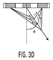
図3A乃至3Dは、本発明によって実施され得る送信/受信開口構造に関して、様々な構造を表す。即ち、図3A乃至3Dは、毎チャネルRFデータから再構成されるフローファントムのカラーフロー画像を示す。図3Aは、従来の受信構造の使用を表す。図3Bは、φ1=2.5°の場合の受信構造の使用を表す。図3Cは、φ2=5°の場合の受信構造の使用を表す。図3Dは、φ3=7.5°の場合の受信構造の使用を表す。 3A-3D represent various structures with respect to transmit / receive aperture structures that may be implemented in accordance with the present invention. That is, FIGS. 3A to 3D show color flow images of a flow phantom reconstructed from each channel RF data. FIG. 3A represents the use of a conventional receiving structure. FIG. 3B represents the use of the receiving structure when φ1 = 2.5 °. FIG. 3C represents the use of the receiving structure when φ2 = 5 °. FIG. 3D represents the use of the receiving structure when φ3 = 7.5 °.
図4は、必要とされる基本計算を表し、ここで、
![]()
![]()
![]()
![]()
![]()
![]()
![]()
![]()
![]()
![]()

![]()
![]()
![]()
![]()
![]()
![]()
![]()
![]()
![]()
![]()
![]()
![]()
様々な視点の間のスペックルパターンにおける相関関係の欠如の結果として、スペックルパターンにおける不一致は、目的の画像を劣化させることなく低減され得る。スペックルを低減するために様々な視点から形成される画像を数学的に結合する計算は、よく知られる。通常、“固定”トランスデューサを用いて異なる方向からの多数の画像を生成する方法は、圧電トランスデューサ素子の線形又は円弧状線形配列の異なるセル又はセルのグループを励起することである。圧電トランスデューサ素子は、超音波エネルギを発生させ且つ受信するために使用される。超音波ビームに対する視点は、通常、超音波ビームを形成するために使用されるアクティブ開口の物理的位置によって制御される。このように、固定トランスデューサにおけるグループは、必要とされる空間的に分離された視点を得るために、配列に沿って分けられるべきである。 As a result of the lack of correlation in the speckle pattern between the various viewpoints, the mismatch in the speckle pattern can be reduced without degrading the target image. Calculations that mathematically combine images formed from different viewpoints to reduce speckle are well known. Typically, the method of generating multiple images from different directions using “fixed” transducers is to excite different cells or groups of cells in a linear or arcuate linear array of piezoelectric transducer elements. Piezoelectric transducer elements are used to generate and receive ultrasonic energy. The viewpoint for the ultrasound beam is usually controlled by the physical position of the active aperture used to form the ultrasound beam. Thus, groups in fixed transducers should be divided along the array to obtain the required spatially separated viewpoints.
一例として、N個のトランスデューサ素子の線形配列をM個のセクションに分けることができる。夫々のセクションは、N/Mの隣接するトランスデューサを有し、配列に沿った一意の位置又は視点によって定められる。夫々のセクションは、全てのMのビームが実質的に同じ領域で焦点を合わせられるように向けられたトランスデューサセクションの夫々からであるが、トランスデューサ配列の正面にその原点を有する異なった方向からの結果として得られる超音波ビームを有して、連続してある点で1つを電気的に励起され得る。その場合、スペックルは、関連するM個の異なる視点からの(送信及び受信の両方の処理によって制御される)Mの超音波ビームを結合することによって低減され得る。 As an example, a linear array of N transducer elements can be divided into M sections. Each section has N / M adjacent transducers and is defined by a unique position or viewpoint along the array. Each section is from each of the transducer sections oriented so that all M beams are focused in substantially the same area, but the results from different directions with their origin in front of the transducer array. One can be electrically excited at a point in succession with the resulting ultrasonic beam. In that case, speckle may be reduced by combining M ultrasound beams (controlled by both transmit and receive processing) from M different viewpoints involved.
図5A乃至5Dは、毎チャネルRFデータから再構成されたフローファントムのCPA画像を表す。即ち、図5Aは、従来の受信構造により受信されるデータから再構成される画像を表し、図5Bは、φ1=2.5°の場合に本発明の受信構造により受信されるデータから再構成された画像を表し、図5Cは、φ2=5°の場合の受信構造を表し、図5Dは、φ3=7.5°の場合の受信構造の使用を表す。 FIGS. 5A-5D represent flow phantom CPA images reconstructed from per-channel RF data. That is, FIG. 5A represents an image reconstructed from data received by the conventional receiving structure, and FIG. 5B is reconstructed from data received by the receiving structure of the present invention when φ1 = 2.5 °. FIG. 5C represents the receiving structure when φ2 = 5 °, and FIG. 5D represents the use of the receiving structure when φ3 = 7.5 °.
本発明に従うCFI及びCPAフローデータから再構成される更なるスクリーンショットは、図6A乃至6Dに示されている。具体的に、図6Bは、従来のフロー画像(図6A)と比較して、欠陥がより少ない合成CFI画像を表し、血管腔内のフローのより好ましい描写を示す。図6Dの合成CPAは、方位分解能のより一層の劣化を伴うことなく、従来のCPA(図6C)に比べて、低減されたスペックルパターン及びより良い充填(filling)を示す。図6A乃至6Bを見ることによって容易に理解され得るように、本発明の技術は、(開口の大きさに起因する)スペクトル拡張と、方位分解能との間の妥協を提供する。この技術は、また、カラーフロー画像形成の感度を高めることができる。 Further screenshots reconstructed from CFI and CPA flow data according to the present invention are shown in FIGS. 6A-6D. Specifically, FIG. 6B represents a synthetic CFI image with fewer defects compared to a conventional flow image (FIG. 6A), showing a more preferred depiction of the flow in the vessel lumen. The composite CPA of FIG. 6D shows a reduced speckle pattern and better filling compared to conventional CPA (FIG. 6C) without further degradation of azimuthal resolution. As can be readily understood by looking at FIGS. 6A-6B, the technique of the present invention provides a compromise between spectral expansion (due to aperture size) and azimuthal resolution. This technique can also increase the sensitivity of color flow image formation.
本発明のアプローチは、合成角度を有してマルチライン要素を交互に使用することによってBorisプラットフォームにおいて実施され得る。4xマルチラインの場合、合成は適用され得ない。2xマルチラインの場合には、2つの合成角度が得られる(従来の構造並びにb、c又はd構造のうちの1つ)。マルチラインがない場合、4つの合成角度が使用され得る。ついでに言えば、本発明は、QSCが16の平行な受信経路を有するので、Borisプラスアーキテクチャにより良くマッピングし、従って、1次元配列に関して、同時に4つの合成角度を有して4xマルチラインを実現することが可能である。当業者には明らかなように、本発明を実施するようBorisを変形することは、“新たな”取得テーブルの準備を必要とする。当業者であって、特許権を有するBorisプラットフォームを理解する者には明らかなように、新たな又は修正された取得テーブルは、ここに記載される新しい受信開口構造をサポートするために定義される必要があり、FECは、本発明の開口配置を取り込む必要がある。また当業者には明らかなように、プラットフォームは本発明の限定ではなく、受信開口配置及びその配置からのデータの処理をサポートすることができる如何なるプラットフォームも、ここで記載及び請求されるフロー画像形成において改善される合成を実施することができる。 The approach of the present invention can be implemented on the Boris platform by alternately using multiline elements with composite angles. In the case of 4x multiline, no synthesis can be applied. In the case of a 2x multiline, two composite angles are obtained (conventional structure and one of b, c or d structures). In the absence of multilines, four composite angles can be used. Incidentally, the present invention maps better to the Boris plus architecture because the QSC has 16 parallel receive paths, and thus achieves 4x multi-line with 4 composite angles simultaneously for a one-dimensional array. It is possible. As will be apparent to those skilled in the art, transforming Boris to implement the present invention requires the preparation of a “new” acquisition table. As will be apparent to those skilled in the art and understanding the patented Boris platform, a new or modified acquisition table is defined to support the new receive aperture structure described herein. There is a need and the FEC needs to capture the aperture arrangement of the present invention. It will also be apparent to those skilled in the art that the platform is not a limitation of the present invention, and any platform capable of supporting the processing of the receive aperture arrangement and data from that arrangement is described and claimed herein. An improved synthesis can be performed.
Borisプラットフォームの例に戻り、DSCアーキテクチャは、異なるルックアングルが派生的なマルチラインとして処理され得るので、変更される必要はない。当然、異なる正規化関数が異なる受信構造に適用される必要があることは容易に理解されるべきである。ついでに言えば、フィリップスが権利を所有するBorisSIPは、定期的なカラーフロー/CPA処理を実行する前に、異なる角度を合成すべく変形を必要とする。 Returning to the example of the Boris platform, the DSC architecture does not need to be changed because different look angles can be treated as derivative multilines. Of course, it should be readily understood that different normalization functions need to be applied to different receiving structures. Incidentally, the Boris SIP, for which Philips owns rights, needs to be modified to combine different angles before performing regular color flow / CPA processing.
図7A乃至7Dは、夫々、スクリーン処置の前後における画像品位の差を明らかにするよう、従来のカラーフロー画像、合成カラーフロー画像、従来のCPA画像、及び合成CPA画像を表す。即ち、4つの図は、本発明に従って実施されるフロー処理の間にスペックルを除去するための合成の結果及び利点の理解を与える。ついでに言えば、これによって開示される発明は、例えば、甲状腺又は胸部にあるような小さな血管の画像形成において血小板が影を作りうる狭窄の存在下で、浅い血管への適用に特に適する。 7A to 7D respectively show a conventional color flow image, a combined color flow image, a conventional CPA image, and a combined CPA image so as to clarify the difference in image quality before and after the screen treatment. That is, the four figures provide an understanding of the results and advantages of synthesis to remove speckle during flow processing performed in accordance with the present invention. Incidentally, the invention disclosed thereby is particularly suitable for application to shallow blood vessels in the presence of stenosis where platelets can shadow in the imaging of small blood vessels, such as in the thyroid or breast.
留意すべきは、表される機能的動作を実行するために必要とされるソフトウェア及び/又は2次元で超音波画像を空間的に合成するために必要な数学的結合及びデータ操作は、論理関数を実施するための実行可能な命令の順序付きリストを有することができる点である。このように、ソフトウェアは、例えば、コンピュータベースのシステム、処理装置内蔵システム又は命令実行システム、機器若しくは装置から命令を読み出して、その命令を実行する他のシステムのような命令実行システム、機器又は装置によって、あるいは、それらと共に使用される如何なるコンピュータ読取可能な媒体においても具現され得る。本願に照らして、“コンピュータ読取可能な媒体”は、命令実行システム、機器又は装置によって、あるいは、それらと共に使用されるプログラムを含み、記憶し、通信し、伝播し、又は送信することができる如何なる手段であっても良い。 It should be noted that the software required to perform the functional operations represented and / or the mathematical combinations and data manipulations required to spatially synthesize ultrasound images in two dimensions are logical functions. It is possible to have an ordered list of executable instructions to implement In this way, software can be used to read instruction from a computer-based system, processor-embedded system or instruction execution system, apparatus or device, and to execute the instruction, such as an instruction execution system, apparatus or device. Or can be embodied on any computer readable medium used therewith. In the context of this application, a “computer-readable medium” includes any program that can be stored, communicated, propagated or transmitted by or used by or with an instruction execution system, device or apparatus. It may be a means.
コンピュータ読取可能な媒体は、例えば、それに限定されないが、電子、磁気、光学、電磁気、赤外線、若しくは半導体システム、機器、装置又は伝播媒体でありうる。コンピュータ読取可能な媒体のより具体的な例(不完全なリスト)は、以下:1又はそれ以上のワイヤを有する電気接続(電子)、携帯型のコンピュータディスケット(磁気)、ランダムアクセスメモリ(RAM)(磁気)、読み出し専用メモリ(ROM)(磁気)、消去可能なプログラマブルROM(EPROM若しくはフラッシュ)(磁気)、光ファイバ(光学)、及び携帯型コンパクトディスクROM(CDROM)(光学)を含みうる。留意すべきは、コンピュータ読取可能な媒体は、プログラムが、例えば、紙又は他の媒体の光学走査を介して電子的に捕捉されて、必要ならば、適切な方法で適合、解釈又は処理をなされて、コンピュータメモリに格納され得る場合に、プログラムが印刷されている紙又は他の適切な媒体でありうる点である。 The computer readable medium can be, for example but not limited to, an electronic, magnetic, optical, electromagnetic, infrared, or semiconductor system, apparatus, device, or propagation medium. More specific examples (incomplete list) of computer readable media are: electrical connections (electronic) with one or more wires, portable computer diskette (magnetic), random access memory (RAM) (Magnetic), read only memory (ROM) (magnetic), erasable programmable ROM (EPROM or flash) (magnetic), optical fiber (optical), and portable compact disc ROM (CDROM) (optical). It should be noted that a computer readable medium is a program that is captured electronically, for example via optical scanning of paper or other media, and adapted, interpreted or processed in an appropriate manner if necessary. Thus, where it can be stored in computer memory, it can be paper or other suitable medium on which the program is printed.
留意すべきは、本発明の上記実施例、具体的に、如何なる“好ましい”実施例も、単に、本発明の原理の明りょうな理解のために挙げられているに過ぎない可能な実施の例である。更に、多数の変更及び変形は、本発明の精神及び原理から著しく逸脱することなく、本発明の上記実施例に対して行われ得る。全てのこのような変更及び変形は、本発明の適用範囲内に含まれ且つ特許請求の範囲によって保護される本開示によって示されるよう意図される。 It should be noted that the above embodiments of the present invention, in particular, any “preferred” embodiment, are merely possible examples of implementations that are merely given for a clear understanding of the principles of the present invention. It is. In addition, many modifications and variations may be made to the above embodiments of the invention without departing significantly from the spirit and principles of the invention. All such modifications and variations are intended to be shown by the present disclosure, which is within the scope of the invention and protected by the claims.
Claims (14)
前記複数の時間インターリーブ信号を中継して、該信号を単一の開口を介して送信するよう構成される、前記送信器と通信するトランスデューサ;
前記単一の開口の一方の側に配置されて、ビーム形成技術によって同時に様々な角度で複数の応答走査ビームを取得する隣接する組のトランスデューサ素子によって定められる2又はそれ以上の副開口において複数の受信信号を受信するよう構成される、前記トランスデューサと通信する受信器;
前記複数の応答走査ビームから得られる画像情報を数学的に表示信号として合成するよう構成される、前記受信器と通信する信号処理装置;及び
前記表示信号を画像に変換するよう構成される、前記信号処理装置と通信するモニタ;
を有する超音波画像形成システム。 A transmitter configured to generate a plurality of time interleaved transmit signals;
A transducer in communication with the transmitter configured to relay the plurality of time-interleaved signals and transmit the signals through a single aperture;
A plurality of sub-apertures in two or more sub-apertures positioned on one side of the single aperture and defined by adjacent sets of transducer elements that simultaneously acquire a plurality of response scanning beams at various angles by beamforming techniques. A receiver in communication with the transducer configured to receive a received signal;
A signal processing device in communication with the receiver configured to mathematically combine image information obtained from the plurality of response scanning beams as a display signal; and configured to convert the display signal into an image, A monitor in communication with the signal processing device;
An ultrasound imaging system.
送信開口を横切って対称的に第1の組のトランスデューサ素子として定められる第1の受信開口から発せられるよう、第1の組の超音波応答走査ビームを生成するステップ;
前記送信開口を横切って対称的に配置される少なくとも第2の組のトランスデューサ素子によって定められる前記第1の受信開口に隣接する少なくとも第2の受信開口から発せられるよう、少なくとも第2の組の超音波応答走査ビームを生成するステップ;及び
画像情報を合成するステップ;
を有し、
前記応答走査ビームは、前記第1の受信開口及び前記少なくとも第2の受信開口によって同時に受信される、超音波画像においてスペックルを減らす方法。 Generating the transmit scanning beam from the single aperture defined in front of the transducer element array such that the transmit scanning beam is emitted from the single aperture;
Generating a first set of ultrasonic response scanning beams to be emitted from a first receive aperture that is symmetrically defined as a first set of transducer elements across the transmit aperture;
At least a second set of superlattices emanating from at least a second receive aperture adjacent to the first receive aperture defined by at least a second set of transducer elements disposed symmetrically across the transmit aperture. Generating a sonic response scanning beam; and synthesizing image information;
Have
The method of reducing speckle in an ultrasound image, wherein the response scanning beam is received simultaneously by the first receive aperture and the at least second receive aperture.
複数の超音波応答走査ビームが異なる注視方向と関連するように、前記単一の送信開口に隣接し且つ該単一の送信開口を中心とする少なくとも2つの受信副開口から夫々発せられる前記複数の超音波応答走査ビームを生成する手段;
同時に複数の注視方向から得られる画像情報を回復する手段;
空間的に合成された画像情報を実現するよう、同時に、前記複数の注視方向から得られる前記回復された画像情報を空間的に合成する手段;及び
オペレータが見ることができるように前記空間的に合成された画像情報を変換する手段;
を有する超音波画像形成システム。 Means for generating and transmitting a transmit scanning beam from a single transmit aperture of the transducer array matrix;
The plurality of ultrasound beams emitted from at least two receiving sub-apertures adjacent to and centered on the single transmission aperture, such that the plurality of ultrasonic response scanning beams are associated with different gaze directions Means for generating an ultrasonic response scanning beam;
Means for recovering image information obtained from a plurality of gaze directions simultaneously;
Means for spatially synthesizing the recovered image information obtained from the plurality of gaze directions simultaneously to realize spatially synthesized image information; and the spatially as seen by an operator Means for converting the synthesized image information;
An ultrasound imaging system.
前記命令の組は、汎用コンピュータによって動作する場合に請求項1に記載される方法を実施する、コンピュータ読取可能な媒体。 A computer readable medium having a set of computer readable instructions comprising:
The computer-readable medium implementing the method of claim 1 when the set of instructions is operated by a general purpose computer.
Applications Claiming Priority (2)
| Application Number | Priority Date | Filing Date | Title |
|---|---|---|---|
| US71318205P | 2005-08-31 | 2005-08-31 | |
| PCT/IB2006/053023 WO2007026319A1 (en) | 2005-08-31 | 2006-08-30 | Ultrasound imaging system and method for flow imaging using real-time spatial compounding |
Publications (1)
| Publication Number | Publication Date |
|---|---|
| JP2009505771A true JP2009505771A (en) | 2009-02-12 |
Family
ID=37670716
Family Applications (1)
| Application Number | Title | Priority Date | Filing Date |
|---|---|---|---|
| JP2008528634A Withdrawn JP2009505771A (en) | 2005-08-31 | 2006-08-30 | Ultrasound imaging system and method for flow imaging with real-time space synthesis |
Country Status (6)
| Country | Link |
|---|---|
| US (1) | US20080242992A1 (en) |
| EP (1) | EP1927015A1 (en) |
| JP (1) | JP2009505771A (en) |
| KR (1) | KR20080039446A (en) |
| CN (1) | CN101253418A (en) |
| WO (1) | WO2007026319A1 (en) |
Cited By (1)
| Publication number | Priority date | Publication date | Assignee | Title |
|---|---|---|---|---|
| CN102551808A (en) * | 2012-02-29 | 2012-07-11 | 飞依诺科技(苏州)有限公司 | Imaging method for graph expansion in ultrasonic diagnosis |
Families Citing this family (19)
| Publication number | Priority date | Publication date | Assignee | Title |
|---|---|---|---|---|
| US20110224548A1 (en) * | 2008-11-14 | 2011-09-15 | Hitachi Medical Corporation | Ultrasonic diagnostic apparatus and method for processing signal of ultrasonic diagnostic apparatus |
| CN102695456B (en) | 2010-11-09 | 2015-03-25 | 柯尼卡美能达株式会社 | Beam-forming method, ultrasonic diagnosis device, and integrated circuit |
| FR2971342B1 (en) * | 2011-02-07 | 2013-03-01 | Supersonic Imagine | IMAGING DEVICE WITH CADENCE OPTIMIZATION |
| US8968205B2 (en) * | 2011-02-10 | 2015-03-03 | Siemens Medical Solutions Usa, Inc. | Sub-aperture control in high intensity focused ultrasound |
| JP5435751B2 (en) * | 2011-03-03 | 2014-03-05 | 富士フイルム株式会社 | Ultrasonic diagnostic apparatus, ultrasonic transmission / reception method, and ultrasonic transmission / reception program |
| CN103156636B (en) * | 2011-12-15 | 2016-05-25 | 深圳迈瑞生物医疗电子股份有限公司 | A kind of supersonic imaging device and method |
| US9335194B2 (en) * | 2013-09-16 | 2016-05-10 | Agena A/S | System or a method for measuring flow of fluid or gas |
| EP3247280B1 (en) * | 2015-01-15 | 2023-07-12 | Herring, Rodney | Diffuse acoustic confocal imager |
| CN104586433B (en) * | 2015-02-02 | 2016-08-24 | 声泰特(成都)科技有限公司 | First-harmonic based on frequency conversion/harmonic wave merges the formation method combined with space compound |
| CN114469173A (en) * | 2015-06-05 | 2022-05-13 | 深圳迈瑞生物医疗电子股份有限公司 | Ultrasonic fluid imaging system |
| US11531096B2 (en) | 2017-03-23 | 2022-12-20 | Vave Health, Inc. | High performance handheld ultrasound |
| US11446003B2 (en) | 2017-03-27 | 2022-09-20 | Vave Health, Inc. | High performance handheld ultrasound |
| US10856843B2 (en) | 2017-03-23 | 2020-12-08 | Vave Health, Inc. | Flag table based beamforming in a handheld ultrasound device |
| US10469846B2 (en) | 2017-03-27 | 2019-11-05 | Vave Health, Inc. | Dynamic range compression of ultrasound images |
| CA3057587A1 (en) * | 2017-03-23 | 2018-09-27 | Vave Health, Inc. | High performance handheld ultrasound |
| JP7079680B2 (en) * | 2018-07-05 | 2022-06-02 | 富士フイルムヘルスケア株式会社 | Ultrasound imaging device and image processing device |
| CN112672693A (en) * | 2018-09-27 | 2021-04-16 | 深圳迈瑞生物医疗电子股份有限公司 | Space composition method and system and computer readable storage medium |
| US20220249064A1 (en) * | 2019-06-11 | 2022-08-11 | Koninklijke Philips N.V. | Methods and systems for speckle reduction |
| CN111227867B (en) * | 2020-03-10 | 2021-01-12 | 云南大学 | Ultrasonic Doppler blood flow imaging method and system |
Family Cites Families (12)
| Publication number | Priority date | Publication date | Assignee | Title |
|---|---|---|---|---|
| US4159462A (en) * | 1977-08-18 | 1979-06-26 | General Electric Company | Ultrasonic multi-sector scanner |
| US4319486A (en) * | 1980-02-07 | 1982-03-16 | Trippensee Corporation | Reversing thermometer frame |
| CA1242267A (en) * | 1984-09-25 | 1988-09-20 | Rainer Fehr | Real time display of an ultrasonic compound image |
| JP2777197B2 (en) * | 1989-06-13 | 1998-07-16 | 株式会社東芝 | Ultrasound diagnostic equipment |
| US5398216A (en) * | 1993-08-30 | 1995-03-14 | General Electric Company | Method for detecting two-dimensional flow for ultrasound color flow imaging |
| US5522393A (en) * | 1994-05-24 | 1996-06-04 | Duke University | Multi-dimensional real-time ultrasonic blood flow imaging apparatus and method |
| US6390980B1 (en) * | 1998-12-07 | 2002-05-21 | Atl Ultrasound, Inc. | Spatial compounding with ultrasonic doppler signal information |
| US7399279B2 (en) * | 1999-05-28 | 2008-07-15 | Physiosonics, Inc | Transmitter patterns for multi beam reception |
| US6350241B1 (en) * | 1999-12-27 | 2002-02-26 | Ge Medical Systems Global Technology Company, Llc | Method and apparatus for multiple angle compound flow imaging |
| US6464637B1 (en) * | 2000-06-23 | 2002-10-15 | Koninklijke Philips Electronics N.V. | Automatic flow angle correction by ultrasonic vector |
| US6464638B1 (en) * | 2000-10-05 | 2002-10-15 | Koninklijke Philips Electronics N.V. | Ultrasound imaging system and method for spatial compounding |
| US6508770B1 (en) * | 2001-03-08 | 2003-01-21 | Acuson Corporation | Aperture compounding for medical imaging |
-
2006
- 2006-08-30 JP JP2008528634A patent/JP2009505771A/en not_active Withdrawn
- 2006-08-30 CN CNA2006800316493A patent/CN101253418A/en active Pending
- 2006-08-30 EP EP06795833A patent/EP1927015A1/en not_active Withdrawn
- 2006-08-30 KR KR1020087004762A patent/KR20080039446A/en not_active Application Discontinuation
- 2006-08-30 WO PCT/IB2006/053023 patent/WO2007026319A1/en active Application Filing
- 2006-08-30 US US12/065,153 patent/US20080242992A1/en not_active Abandoned
Cited By (1)
| Publication number | Priority date | Publication date | Assignee | Title |
|---|---|---|---|---|
| CN102551808A (en) * | 2012-02-29 | 2012-07-11 | 飞依诺科技(苏州)有限公司 | Imaging method for graph expansion in ultrasonic diagnosis |
Also Published As
| Publication number | Publication date |
|---|---|
| WO2007026319A1 (en) | 2007-03-08 |
| EP1927015A1 (en) | 2008-06-04 |
| CN101253418A (en) | 2008-08-27 |
| KR20080039446A (en) | 2008-05-07 |
| US20080242992A1 (en) | 2008-10-02 |
Similar Documents
| Publication | Publication Date | Title |
|---|---|---|
| JP2009505771A (en) | Ultrasound imaging system and method for flow imaging with real-time space synthesis | |
| US6464638B1 (en) | Ultrasound imaging system and method for spatial compounding | |
| US6969353B2 (en) | Contrast-agent enhanced color-flow imaging | |
| US8038618B2 (en) | Ultrasound-imaging systems and methods for a user-guided three-dimensional volume-scan sequence | |
| US6827686B2 (en) | System and method for improved harmonic imaging | |
| JP5470260B2 (en) | Organizational Doppler image forming apparatus and method using composite image | |
| US7338448B2 (en) | Method and apparatus for ultrasound compound imaging with combined fundamental and harmonic signals | |
| JP2004000613A (en) | Display method for subtraction imaging method | |
| JP2011526181A (en) | High frame rate quantitative Doppler flow imaging using unfocused transmit beams | |
| US7056290B2 (en) | Continuous depth harmonic imaging using transmitted and nonlinearly generated second harmonics | |
| US6423004B1 (en) | Real-time ultrasound spatial compounding using multiple angles of view | |
| US20180028153A1 (en) | Ultrasound diagnostic apparatus and ultrasound imaging method | |
| US8235906B2 (en) | System and method for accelerated focused ultrasound imaging | |
| JP2011212440A (en) | Method and apparatus for ultrasound signal acquisition and processing | |
| JP4445255B2 (en) | Method and apparatus for ultrasonic speckle reduction using broadband frequency synthesis with harmonics generated in tissue | |
| US20220071597A1 (en) | Contrast imaging | |
| JP6838174B2 (en) | Ultrasonic probe and processing method | |
| US11224410B2 (en) | Methods and systems for filtering ultrasound image clutter | |
| JP2004223109A (en) | Apparatus and method for picking up ultrasonic image | |
| JP2022174560A (en) | Ultrasound diagnosis apparatus | |
| JPH02237550A (en) | Ultrasonic diagnostic apparatus | |
| JP2004201864A (en) | Ultrasonic imaging device and the ultrasonic imaging method |
Legal Events
| Date | Code | Title | Description |
|---|---|---|---|
| A621 | Written request for application examination |
Free format text: JAPANESE INTERMEDIATE CODE: A621 Effective date: 20090828 |
|
| A761 | Written withdrawal of application |
Free format text: JAPANESE INTERMEDIATE CODE: A761 Effective date: 20100901 |