JP2009503516A - Positioning adapter for use with radioisotopes - Google Patents

Positioning adapter for use with radioisotopes Download PDF

Info

Publication number
JP2009503516A
JP2009503516A JP2008524114A JP2008524114A JP2009503516A JP 2009503516 A JP2009503516 A JP 2009503516A JP 2008524114 A JP2008524114 A JP 2008524114A JP 2008524114 A JP2008524114 A JP 2008524114A JP 2009503516 A JP2009503516 A JP 2009503516A
Authority
JP
Japan
Prior art keywords
alignment
passage
container
radioisotope generator
adapter
Prior art date
Legal status (The legal status is an assumption and is not a legal conclusion. Google has not performed a legal analysis and makes no representation as to the accuracy of the status listed.)
Pending
Application number
JP2008524114A
Other languages
Japanese (ja)
Inventor
ゲイリー・エス・ワグナー
デイビッド・ダブリュー・ウィルソン
フランク・エム・ファーゴ
ラルフ・イー・ポラード・ジュニア
Current Assignee (The listed assignees may be inaccurate. Google has not performed a legal analysis and makes no representation or warranty as to the accuracy of the list.)
Mallinckrodt Inc
Original Assignee
Mallinckrodt Inc
Priority date (The priority date is an assumption and is not a legal conclusion. Google has not performed a legal analysis and makes no representation as to the accuracy of the date listed.)
Filing date
Publication date
Application filed by Mallinckrodt Inc filed Critical Mallinckrodt Inc
Publication of JP2009503516A publication Critical patent/JP2009503516A/en
Pending legal-status Critical Current

Links

Images

Classifications

    • GPHYSICS
    • G21NUCLEAR PHYSICS; NUCLEAR ENGINEERING
    • G21GCONVERSION OF CHEMICAL ELEMENTS; RADIOACTIVE SOURCES
    • G21G4/00Radioactive sources
    • GPHYSICS
    • G21NUCLEAR PHYSICS; NUCLEAR ENGINEERING
    • G21FPROTECTION AGAINST X-RADIATION, GAMMA RADIATION, CORPUSCULAR RADIATION OR PARTICLE BOMBARDMENT; TREATING RADIOACTIVELY CONTAMINATED MATERIAL; DECONTAMINATION ARRANGEMENTS THEREFOR
    • G21F5/00Transportable or portable shielded containers
    • G21F5/015Transportable or portable shielded containers for storing radioactive sources, e.g. source carriers for irradiation units; Radioisotope containers

Abstract

本発明は、ある特徴では、放射性同位体溶出手順で使用される位置合せアダプタに向けられていると言える。ある実施形態では、位置合せアダプタは溶出システムの種々の要素を位置合せするのを少なくとも支援するのに使用される。例えば、ある実施形態では、溶出システムの蓋に形成された開口と放射性同位体発生器の溶出針とを少なくとも概略的に一致させることを支援するのに使用されてもよい。ある実施形態では、位置合せアダプタは、溶出アセンブリ(例えば、溶出液バイアルを収容する溶出シールド)と放射性同位体発生器の溶出針を少なくとも概略的に一致させることに使用されてもよい。さらに、ある実施形態では、位置合せアダプタは溶離剤容器(例えば溶離剤ボトル)と放射性同位体発生器を少なくとも概略的に一致させることに使用されてもよい。  In one aspect, the present invention can be said to be directed to an alignment adapter used in a radioisotope elution procedure. In some embodiments, the alignment adapter is used to at least assist in aligning the various elements of the elution system. For example, in certain embodiments, it may be used to help at least approximately match the opening formed in the lid of the elution system with the elution needle of the radioisotope generator. In certain embodiments, an alignment adapter may be used to at least approximately match the elution assembly (eg, elution shield containing the eluate vial) and the elution needle of the radioisotope generator. Further, in some embodiments, an alignment adapter may be used to at least approximately match the eluent container (eg, eluent bottle) and the radioisotope generator.

Description

本発明は、一般には核医療の分野に関する。詳しくは、本発明は、放射性同位体発生器から核医療で使用する放射能材料を(例えば溶出アセンブリを介して)抽出できるように構成された溶出システムの構成部品を位置決めシステム及び方法に関する。   The present invention relates generally to the field of nuclear medicine. Specifically, the present invention relates to a system and method for positioning components of an elution system configured to extract (eg, via an elution assembly) radioactive material for use in nuclear medicine from a radioisotope generator.

この項は、以下に記載され及び/又は請求された本発明の種々の特徴に関係する種々の技術の特徴を読者に紹介することを意図している。ここでの議論は、本発明の種々の特徴のより良い理解を助けるために読者に背景情報を与えるのに有益であると信じる。したがって、これらの説明はこの点に照らして読むべきであり、従来技術の吸入としてではない。   This section is intended to introduce the reader to various technical features related to various features of the invention described and / or claimed below. The discussion here is believed to be useful in providing the reader with background information to help a better understanding of the various features of the present invention. Accordingly, these descriptions should be read in light of this and not as prior art inhalation.

核医療は、患者の器官又は生物学的領域に濃縮する小投与量の放射性物質を患者に注入することで、診断及び治療目的で放射性物質を利用する。核医療に典型的に使用される放射性物質は、テクネチウム-99m、インジウム-113m、ストロンチウム-87mその他を含む。いくつかの放射性物質は患者の組織に向かって自然に濃縮し、例えばヨードは甲状腺に向かって濃縮する。しかしながら、放射性物質はしばしば標識剤又は器官親和性物質(organ-seeking agent)と組み合わされ、これは患者の所望の器官又は生物学的領域に対する放射性物質を目標とする。単独で又は標識剤と組み合わせたこれらの放射性物質は、典型的には、核医療の分野で放射性薬剤として規定されている。比較的小容量の放射性薬剤で、放射線画像形成システム(例えば、ガンマカメラ)は、放射性薬剤を収集する器官又は生物学的領域の画像を提供する。画像の不規則性は多くの場合、癌のような病的状態を示す。高投与量の放射性薬剤は、癌細胞のような病的組織に直接、治療線量の放射線を供給するのに使用されている。   Nuclear medicine utilizes a radioactive material for diagnostic and therapeutic purposes by injecting the patient with a small dose of the radioactive material that concentrates in the organ or biological area of the patient. Radioactive materials typically used in nuclear medicine include technetium-99m, indium-113m, strontium-87m and others. Some radioactive material naturally concentrates towards the patient's tissue, for example iodine concentrates towards the thyroid. However, radioactive materials are often combined with labeling or organ-seeking agents, which target the radioactive material for the desired organ or biological region of the patient. These radioactive substances, alone or in combination with labeling agents, are typically defined as radiopharmaceuticals in the field of nuclear medicine. With a relatively small volume of radiopharmaceutical, a radiographic imaging system (eg, a gamma camera) provides an image of an organ or biological region that collects the radiopharmaceutical. Image irregularities often indicate a pathological condition such as cancer. High doses of radiopharmaceuticals are used to deliver therapeutic doses of radiation directly to pathological tissues such as cancer cells.

放射性薬剤を製造、梱包、輸送、注出及び投与するのに、種々のシステムが使用されている。これらのシステムは、容器の雌雄コネクタのような要素の手動位置合わせを必要とする。残念ながら、雄コネクタは対応する雌コネクタとのずれにより損傷をすることがある。例えば、中空針が雌コネクタとのずれにより、曲がり、つぶれ、又は破損することがある。この結果、システムは有効に動作しないか、完全に役に立たなくなる。システムが放射性薬剤を収容していると、損傷したコネクタは金銭的損失になり、核医療手順を遅らせ、及び/又は技術者(又は他の個人)が望ましくない放射線に曝される。   Various systems have been used to manufacture, package, transport, dispense and administer radiopharmaceuticals. These systems require manual alignment of elements such as the male and female connectors on the container. Unfortunately, the male connector can be damaged by misalignment with the corresponding female connector. For example, the hollow needle may be bent, crushed, or damaged due to a deviation from the female connector. As a result, the system does not work effectively or is completely useless. If the system contains a radiopharmaceutical, the damaged connector is a financial loss, delays the nuclear medical procedure, and / or exposes the technician (or other individual) to unwanted radiation.

本発明は、ある実施形態では、放射性薬剤溶出システムの要素の位置合わせに向けられている。1つの点に関して、本発明は、放射性同位体溶出手順で使用される位置合せアダプタに向けられていると言ってもよい。例えば、位置合せアダプタは、放射性同位体発生器の種々の要素を位置合わせするのを少なくとも支援し、及び/又は溶出アセンブリ(例えば、そこに配置された溶出液バイアル等を有する溶出シールド)と放射性同位体発生器の要素(例えば中空針)を一致させるのを少なくとも支援するのに使用される。この位置合せアダプタは、全体的に、本体と該本体の外縁にある外壁とを有する。外壁は、放射性同位体発生器が少なくとも部分的に配置される補助シールドの凹部の寸法と密着して嵌合するように形成されてもよい。位置合せアダプタは、本体の内部領域に、発生器の上部の寸法と密着して嵌合するように形成された内部構造を有していてもよい。追加又は代案として、位置合せアダプタは本体を貫通して延びる1又は複数の通路を有していてもよい、1又は複数の通路は、溶出アセンブリ、溶離剤容器、又はこれらの組合せの寸法と密着して嵌合するように形成されてもよい。ある実施形態では、1又は複数の通路は、発生器の1又は複数の所望の要素(例えば中空針)に対して実質的に芯出しされてもよい。   The present invention is directed in certain embodiments to the alignment of elements of a radiopharmaceutical elution system. In one respect, it may be said that the present invention is directed to an alignment adapter used in a radioisotope elution procedure. For example, the alignment adapter at least assists in aligning the various elements of the radioisotope generator and / or is radioactive with an elution assembly (eg, an elution shield having an eluate vial, etc. disposed therein). Used to at least assist in matching elements of the isotope generator (eg hollow needle). The alignment adapter generally has a main body and an outer wall at the outer edge of the main body. The outer wall may be formed in close contact with the size of the recess of the auxiliary shield in which the radioisotope generator is at least partially disposed. The alignment adapter may have an internal structure formed to fit closely into the upper region of the generator in the internal region of the main body. Additionally or alternatively, the alignment adapter may have one or more passages extending through the body, the one or more passages being in close contact with the dimensions of the elution assembly, eluent container, or combinations thereof And may be formed to fit. In certain embodiments, the one or more passages may be substantially centered with respect to one or more desired elements of the generator (eg, a hollow needle).

ある局面は、以下に説明する当初の請求の範囲の発明と範囲が対応している。これらの局面は読者に本発明が取りうるある形態の概要を提供するためにのみ存在し、これらの局面は本発明の範囲を限定するものではないことを理解すべきである。実際には、本発明は以下に説明しない種々の特徴と局面を包含してもよい。   An aspect corresponds to the invention of the scope of the original claims described below. It should be understood that these aspects exist only to provide the reader with an overview of certain forms that the invention can take, and that these aspects do not limit the scope of the invention. Indeed, the invention may encompass a variety of features and aspects not described hereinafter.

本発明の第1の局面によると、放射性同位体発生器と、溶離剤容器と、互いに連結された溶離剤位置合せ部と溶出液位置合せ部とからなる位置合せアダプタとからなる溶出システムが提供されている。前記位置合せアダプタは、前記放射性同位体発生器と前記溶離剤容器との間に配置されている。前記溶離剤容器は、前記溶離剤位置合せ部により前記放射性同位体発生器と解放可能に接続されてほぼ一致している。例えば、溶離剤位置合せ部は
溶離剤容器の回りに密着して嵌合し、放射性同位体発生器の入口中空針と一致する第1通路を有する。さらなる実施例では、溶離剤位置合せ部は、放射性同位体発生器の出口中空針と一致する第2容器を有していてもよい。
According to a first aspect of the present invention, there is provided an elution system comprising a radioisotope generator, an eluent container, and an alignment adapter comprising an eluent alignment unit and an eluent alignment unit connected to each other. Has been. The alignment adapter is disposed between the radioisotope generator and the eluent container. The eluent container is releasably connected to and substantially coincides with the radioisotope generator by the eluent alignment section. For example, the eluent alignment portion closely fits around the eluent container and has a first passage that coincides with the inlet hollow needle of the radioisotope generator. In a further embodiment, the eluent alignment portion may have a second container that coincides with the exit hollow needle of the radioisotope generator.

本発明の第2の特徴によると、放射性同位体発生器アセンブリのための位置合せアダプタが提供されている。位置合せアダプタは、本体と、該本体に結合された放射性同位体発生器位置合せ構造とを含んでいてもよい。位置合せアダプタは前記本体を貫通して配置された第1容器位置合せ通路を有していてもよい。さらに、位置合せアダプタは前記第1容器通路に隣接して前記本体を貫通するように配置された第1容器位置合せ通路を有していてもよい。   According to a second aspect of the invention, an alignment adapter for a radioisotope generator assembly is provided. The alignment adapter may include a body and a radioisotope generator alignment structure coupled to the body. The alignment adapter may have a first container alignment passage disposed through the body. Furthermore, the alignment adapter may have a first container alignment passage disposed adjacent to the first container passage and extending through the main body.

本発明の第3の局面によると、放射性同位体発生器アセンブリが提供されている。このアセンブリは、第1中空針を有する放射性同位体発生器を有し、前記第1中空針は前記発生器の上部に配置されている。アセンブリはまた、発生器の上部と密着して嵌合する位置合せアダプタを有していてもよい。さらに、位置合せアダプタは、前記第1中空針に対してほぼ芯出しされた第1通路を有している。第1通路は、第1中空針と結合可能(すなわち結合することができる)第1容器の寸法と密着して嵌合するように形成されてもよい。位置合せアダプタはまた、第1通路に延びる溶出覗き窓を有していてもよい。   According to a third aspect of the present invention, a radioisotope generator assembly is provided. The assembly includes a radioisotope generator having a first hollow needle, the first hollow needle being disposed on top of the generator. The assembly may also have an alignment adapter that fits closely with the top of the generator. Further, the alignment adapter has a first passage substantially centered with respect to the first hollow needle. The first passage may be formed in close contact with the size of the first container that can be coupled (that is, can be coupled) with the first hollow needle. The alignment adapter may also have an elution viewing window extending to the first passage.

本発明の第4の局面によると、 放射性同位体発生器に解放可能に取り付けられた構造を第1通路に密着して嵌合することにより第1容器を案内し、前記第1容器を前記放射性同位体発生器の第1中空針と係合させることを含む方法が提供されている。この方法はまた、前記構造を第2通路に密着して嵌合することにより第2容器を案内して、前記放射性同位体発生器の第2中空針と係合(例えば、実質的に芯出しして係合)させることを含んでいてもよい。   According to the fourth aspect of the present invention, the first container is guided by closely fitting the structure attached releasably to the radioisotope generator in close contact with the first passage. A method is provided that includes engaging a first hollow needle of an isotope generator. The method also guides the second container by closely fitting the structure to the second passage and engages (eg, substantially centers) the second hollow needle of the radioisotope generator. Engaging).

本発明の第5の特徴は、放射性同位体発生器を有する溶出システムが提供されている。このシステムは、凹部と該凹部への開口を規定する補助放射線シールドと、開口を横切るように取り外し可能に配置されたカバーを有していてもよく、放射性同位体発生器は前記凹部の内側に配置されてもよい。さらに、本ステムは、放射性同位体発生器とカバーの間の補助放射線シールドの内側に配置された少なくとも1つの位置合せアダプタを有していてもよい。前記カバーを通る通路は、位置合せアダプタを介して放射性同位体発止液の少なくとも1つのコネクタと一致していてもよい。   According to a fifth aspect of the present invention, an elution system having a radioisotope generator is provided. The system may include a recess, an auxiliary radiation shield that defines an opening into the recess, and a cover that is removably disposed across the opening, and the radioisotope generator is located inside the recess. It may be arranged. In addition, the stem may have at least one alignment adapter disposed inside the auxiliary radiation shield between the radioisotope generator and the cover. The passage through the cover may coincide with at least one connector of the radioisotope stop solution via an alignment adapter.

本発明の第6の局面によると、放射性同位体発生器アセンブリのための蓋プラグが提供されている。蓋プラグは放射線遮蔽材料を有する本体を有していてもよい。本体はヘッド部と、該ヘッド部に結合された嵌合装着位置合せ部とを有していてもよい。嵌合装着位置合せ部は、本体の長さの少なくとも実質的な部分に沿って配置されていてもよい。本体は、嵌合装着位置合せ部の内側に配置された凹部を有していてもよい。中空針通路が本体の端部に配置されてもよい。この中空針通路は凹部と一致してもよい。さらに、蓋プラグは、凹部の内側に配置された容器を有していてもよく、容器の入口は中空針通路と一致していてもよい。   According to a sixth aspect of the present invention, a lid plug for a radioisotope generator assembly is provided. The lid plug may have a body having a radiation shielding material. The main body may have a head portion and a fitting / mounting position aligning portion coupled to the head portion. The fitting / mounting position aligning portion may be arranged along at least a substantial part of the length of the main body. The main body may have a recess disposed inside the fitting and mounting position adjusting portion. A hollow needle passage may be disposed at the end of the body. This hollow needle passage may coincide with the recess. Further, the lid plug may have a container disposed inside the recess, and the inlet of the container may coincide with the hollow needle passage.

本発明の種々の局面に関連して前述した特徴のほか、種々の改良が存在する。さらなる特徴はこれらの種々の局面に組み入れてもよい。これらの改良及び追加の特徴は個別に存在してもよいし、任意に組み合わせてもよい。例えば、1又は複数の図示された実施形態に関連して以下の説明する種々の特徴は、単独又は組み合わせて本願発明の前述した局面のいずれかに組み入れてもよい。重ねて言うが、前述の概要は読者に本発明の特徴と内容を習熟させることのみを意図し、特許請求された本発明の主題を限定するものではない。   In addition to the features described above in connection with various aspects of the present invention, various improvements exist. Additional features may be incorporated into these various aspects. These improvements and additional features may exist individually or in any combination. For example, the various features described below in connection with one or more illustrated embodiments, alone or in combination, may be incorporated into any of the aforementioned aspects of the invention. Again, the foregoing summary is intended only to familiarize the reader with the features and contents of the invention and is not intended to limit the claimed subject matter of the invention.

以下の詳細な説明を添付図面を参照して読まれれば、本発明のこれらの及び他の特徴、局面、利点は、より良く理解される、添付図面において同様の符号は同様の部材を示す。   These and other features, aspects, and advantages of the present invention will be better understood when the following detailed description is read with reference to the accompanying drawings, in which like reference numerals designate like elements, and in which:

本発明の1又は複数の実施形態を以下に説明する。これらの実施形態を簡潔に説明するために、実際の実施の全ての特徴は、明細書に記載されていない。そのような実際の実施の開発では、エンジニアリング又は設計プロジェクトにおけるように、ある実施と他の実施で変化するシステム関連又はビジネス関連の制約の遵守といった開発者の特定の目的を達成するのに、多くの実施目的の決定を行わなければならないことは認識されなければならない。さらに、そのような開発努力は複雑で時間の浪費であるが、それにも拘わらず、この開示の利益を有する当業者にとって設計、製造、組立の日常の仕事である。   One or more embodiments of the invention are described below. In an effort to provide a concise description of these embodiments, not all features of an actual implementation are described in the specification. In the development of such actual implementations, as in engineering or design projects, many are achieved to achieve a developer's specific objectives such as compliance with system-related or business-related constraints that change from one implementation to another. It must be recognized that a decision on the purpose of implementation must be made. Further, such development efforts are complex and time consuming, but nevertheless are routine tasks of design, manufacture and assembly for those skilled in the art having the benefit of this disclosure.

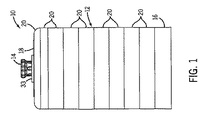
図1は、補助シールド12とシールド溶出アセンブリ14を有する例示的溶出システム10の側面図である。以下にさらに詳細に説明するように、補助シールド12の内側にある種々の容器、中空針、放射性同位体発生器、及びその他の要素の適切な位置合わせを促進するために、様々な位置合わせアダプタ、スリーブ、及び/又は機構を溶出システム10に組み入れてもよい。補助シールド12は、ベース16、蓋18、ベース16と蓋18の間に重ねて配置された複数の段状又は概略階段状のモジュールリング20からなる(図2)。図示された補助シールド12は、該補助シールド12の境界内に放射能を収容するために、鉛及び/又は他の適切な放射能遮蔽材で形成されてもよい。さらに、リング20のモジュール化は補助シールド12の高さに柔軟性を持たせることができ、段状形状は適切な放射線封じ込めを提供する。補助シールドの一つの例が示され、説明されているが、他の補助シールドも適切に使用することができる。   FIG. 1 is a side view of an exemplary elution system 10 having an auxiliary shield 12 and a shield elution assembly 14. Various alignment adapters to facilitate proper alignment of various containers, hollow needles, radioisotope generators, and other elements inside the auxiliary shield 12, as will be described in further detail below. , Sleeves, and / or mechanisms may be incorporated into the elution system 10. The auxiliary shield 12 includes a base 16, a lid 18, and a plurality of step-shaped or substantially step-shaped module rings 20 arranged in an overlapping manner between the base 16 and the lid 18 (FIG. 2). The illustrated auxiliary shield 12 may be formed of lead and / or other suitable radioactive shielding material to contain the radioactivity within the boundary of the auxiliary shield 12. In addition, the modularization of the ring 20 can provide flexibility in the height of the auxiliary shield 12, and the stepped shape provides adequate radiation containment. Although one example of an auxiliary shield is shown and described, other auxiliary shields can be used as appropriate.

図2は、図1の溶出システム10の側面断面図であり、さらに補助シールド12の境界内に配置された放射性同位体発生器22、溶離剤容器24、及び溶離出力又は溶出液容器26を示している。ここで、「溶離剤容器」とは、適切な溶出源流体(例えば食塩水)が配置される又は配置された容器をいう。これに対して、「溶出液」とは、溶出手順で生成される液体溶液等を受け入れ、又は受け入れるように少なくとも概略的に設計されている容器をいう。図示するように、溶離剤容器24は放射性同位体発生器22に1又は複数の入力中空針28(例えば、1対の中空針)を介して結合され、一方溶出液容器26は放射性同位体発生器22に1又は複数の出口中空針30(例えば単一の中空針)を介して結合されている。放射性同位体発生器22に結合されると、容器24,26は放射性同位体発生器22と流体的に連通する(例えば、容器24,26と発生器22の間を流体が流れることができる方法で結合されている)と言える。溶出液容器26はシールド溶出アセンブリ14の溶出シールド32の内側に配置されている。溶出シールド32は鉛、タングステン、タングステン含有プラスチック及び/又は他の適切な放射線遮蔽材で形成されてもよい。以下にさらに詳細に説明するように、溶出システム10の組立、分解、及び/又は使用中に、容器24,26と中空針28,30の適切な位置合わせを促進するために、位置合わせアダプタ34を放射性同位体発生器22と蓋18の間に配置してもよい。位置合わせアダプタ34は、容器24,26と結合し、及び/又は容器24,26から分解するときに、中空針28,30が不注意に一致せず、曲がり、つぶれ、又は損傷する可能性を減少する。ある実施形態では、位置合わせアダプタ34は成形プラスチック構造であり、1又は複数の放射線遮蔽材(例えば、タングステン含浸プラスチック)を含む。このような実施形態では、位置合わせアダプタ34が少なくともいくつかの放射線シールドを提供するように設計されていてもよいので、溶出システム10は、蓋18を含んでいてもよいし、含んでいなくてもよい。   FIG. 2 is a side cross-sectional view of the elution system 10 of FIG. 1, further showing a radioisotope generator 22, an eluent container 24, and an elution output or eluent container 26 disposed within the boundary of the auxiliary shield 12. ing. As used herein, “eluent container” refers to a container in which an appropriate elution source fluid (eg, saline) is or is disposed. In contrast, "eluent" refers to a container that is or at least schematically designed to receive or receive a liquid solution or the like produced by an elution procedure. As shown, eluent container 24 is coupled to radioisotope generator 22 via one or more input hollow needles 28 (eg, a pair of hollow needles), while eluent container 26 is a radioisotope generator. Coupled to the vessel 22 via one or more outlet hollow needles 30 (eg, a single hollow needle). When coupled to the radioisotope generator 22, the containers 24, 26 are in fluid communication with the radioisotope generator 22 (eg, a method that allows fluid to flow between the containers 24, 26 and the generator 22. Can be said). The eluate container 26 is disposed inside the elution shield 32 of the shield elution assembly 14. The elution shield 32 may be formed of lead, tungsten, tungsten-containing plastic and / or other suitable radiation shielding material. As described in more detail below, an alignment adapter 34 may be used to facilitate proper alignment of the containers 24, 26 and the hollow needles 28, 30 during assembly, disassembly, and / or use of the elution system 10. May be placed between the radioisotope generator 22 and the lid 18. When the alignment adapter 34 is coupled to and / or disassembled from the containers 24, 26, the hollow needles 28, 30 may not be inadvertently matched, bent, crushed, or damaged. Decrease. In some embodiments, alignment adapter 34 is a molded plastic structure and includes one or more radiation shielding materials (eg, tungsten impregnated plastic). In such embodiments, the elution system 10 may or may not include the lid 18 because the alignment adapter 34 may be designed to provide at least some radiation shield. May be.

動作時、溶離剤容器24内の溶離剤は、入口中空針28を通り、放射性同位体発生器22を経て、出口中空針30から、溶出液容器26に循環する。前述の溶離剤の循環は放射性物質、例えば放射性同位体を放射性同位体発生器22から溶出液容器26に洗い流し、又は大まかに抽出する。例えば、放射性同位体発生器22の一実施形態は、アルミナのビードの表面に吸収されたモリブデン−99のような放射性親同位体を包囲する放射能遮蔽外部ケーシング(例えば鉛シェル)、又は樹脂交換カラムを有する。放射性同位体発生器22の内側で、親モリブデン−99は、約67時間の半減期で、準安定テクネチウム−99mに変換する。娘放射性同位体、例えばテクネチウム−99mは、親放射性同位体、例えばモリブデン−99よりも弱く(less tightly)放射性同位体発生器22内に保持される。したがって、娘放射性同位体、例えばテクネチウム−99mは、無酸化剤生理食塩水のような適切な溶離剤を用いて、抽出し、又は洗い流すことができる。溶出液容器26内に所望量(例えば所望数の投与回数)の娘放射性同位体、例えばテクネチウム−99mを収集すると、シールド溶出アセンブリ14は溶出システム10から取り出すことができる。以下にさらに詳細に説明するように、抽出された娘放射性同位体は、(例えば核医療施設で)標識剤と組合せて、患者の診断又は治療を促進することができる。   In operation, the eluent in the eluent container 24 circulates through the inlet hollow needle 28, through the radioisotope generator 22, and from the outlet hollow needle 30 to the eluent container 26. The eluent circulation described above flushes or roughly extracts radioactive material, eg, radioisotopes, from the radioisotope generator 22 into the eluent vessel 26. For example, one embodiment of the radioisotope generator 22 may be a radioactive shielding outer casing (eg, lead shell) that encloses a radioactive parent isotope such as molybdenum-99 absorbed on the surface of an alumina bead, or resin replacement. Has a column. Inside the radioisotope generator 22, the parent molybdenum-99 converts to metastable technetium-99m with a half-life of about 67 hours. The daughter radioisotope, such as technetium-99m, is retained in the radioisotope generator 22 less tightly than the parent radioisotope, such as molybdenum-99. Thus, daughter radioisotopes, such as technetium-99m, can be extracted or washed away using a suitable eluent such as non-oxidizing saline. Once the desired amount (eg, the desired number of doses) of the daughter radioisotope, eg, technetium-99m, is collected in the eluate container 26, the shield elution assembly 14 can be removed from the elution system 10. As described in more detail below, the extracted daughter radioisotope can be combined with a labeling agent (eg, at a nuclear medical facility) to facilitate patient diagnosis or treatment.

溶出システム10の動作を考慮して、種々の部材の適切な位置合せは、入口及び出口中空針28,30の寿命と、溶離剤容器24から放射性同位体発生器22を通って溶出液容器26への溶離剤の適切な循環とにとって特に重要である。図示された溶出システム10は、入口中空針28に対する溶離剤容器24の位置合せを向上し、出口中空針30に対する溶出液容器26の位置合せを向上するために、位置合せアダプタ34を含む。以下に詳細に説明するように、位置合せアダプタ34により、技術者は、容器24,26の各々をそれぞれの中空針28,30に向かって所望の(例えば、ほぼ真っ直ぐな)方向に案内することができ、これにより中空針28,30は容器24,26のそれぞれの端部36,38の所望の(例えば中央の)位置に真っ直ぐに進入する。この方法で、位置合せアダプタ34は、容器24,26とそれぞれ結合したときに、中空針28,29の不一致及び偶発的な曲がりや破損の可能性を実質的に減少し又は排除する。   In view of the operation of the elution system 10, proper alignment of the various members is determined by the lifetime of the inlet and outlet hollow needles 28, 30 and the eluent container 26 from the eluent container 24 through the radioisotope generator 22. Particularly important for proper circulation of the eluent to The illustrated elution system 10 includes an alignment adapter 34 to improve the alignment of the eluent container 24 with respect to the inlet hollow needle 28 and to improve the alignment of the eluent container 26 with respect to the outlet hollow needle 30. As described in detail below, the alignment adapter 34 allows the technician to guide each of the containers 24, 26 toward the respective hollow needles 28, 30 in a desired (eg, substantially straight) direction. This allows the hollow needles 28, 30 to go straight into the desired (eg central) position of the respective ends 36, 38 of the containers 24, 26. In this way, the alignment adapter 34 substantially reduces or eliminates the possibility of mismatch and accidental bending or breakage of the hollow needles 28, 29 when coupled to the containers 24, 26, respectively.

位置合せアダプタ34のある実施形態は、種々の容器24,26、補助シールド12、蓋18、発生器22、及び/又は中空針28,30の間の側方運動の遊び、隙間、又は全体的自由状態(general freedom)を実質的に減少する。これにより、要素の適切な位置合せ、及びほぼ直進(例えば上方及び/又は下方)運動を組立及び分解中に達成することができる。要素間にいくらかの隙間や遊びが残るかもしれないが、その隙間はほぼ減少され、要素が組立及び分解中にほぼ真っ直ぐな位置合せされた方向に移動する可能性を増加する比較的密着した嵌合(relatively close fit)を提供する。要素間の「密着嵌合界面(closely fit interface)」は、ここでは少なくとの要素の部分間の実質的に減少した距離をいい、その距離は、所望の方向(例えば、真直ぐに上方又は下方)の(例えば、要素の中心線に沿う)移動に対する傾斜、側方のずれ、全体的不一致の可能性を減少するように選択される。位置合せアダプタ34は、要素の挿入及び取り外し、例えば発生器22に対する容器24,26の下方への挿入及び上方への取り外しの方向への長手方向ガイド構造(例えば、以下に説明する通路66,68)を含む。長手方向ガイド構造は、挿入と取り外しの方向へのガイドの長さを有効に増加する。これにより、挿入及び取り外しの方向に対する傾斜及びずれの可能性(可能性の度合い)が潜在的に減少する。要素間の密着嵌合界面(例えば容器24,26と通路66,68の間)及び長手方向ガイド構造(例えば、通路66,68)は、少なくとも1つの点については、要素(例えば容器24,26と中空針28,30)間の適切な位置合せと接続の可能性を協働して増加する。位置合せアダプタ34の種々の特徴は、図を参照して以下に詳細に説明する。   Certain embodiments of the alignment adapter 34 may include lateral movement play, gaps, or overall between the various containers 24, 26, auxiliary shield 12, lid 18, generator 22, and / or hollow needles 28, 30. Substantially reduce general freedom. Thereby, proper alignment of the elements and substantially straight (eg upward and / or downward) movement can be achieved during assembly and disassembly. Although some gaps or play may remain between the elements, the gaps are substantially reduced and a relatively tight fit that increases the likelihood that the elements will move in a substantially straight aligned direction during assembly and disassembly. Provides a relatively close fit. A “closely fit interface” between elements refers here to a substantially reduced distance between at least a portion of the elements, the distance being in a desired direction (eg, straight up or down). ) (E.g., along the centerline of the element) is selected to reduce the possibility of tilt, lateral deviation, and overall mismatch. The alignment adapter 34 is a longitudinal guide structure (eg, passages 66, 68 described below) in the direction of insertion and removal of elements, eg, downward insertion and removal of containers 24, 26 relative to the generator 22. )including. The longitudinal guide structure effectively increases the length of the guide in the direction of insertion and removal. This potentially reduces the possibility of tilting and shifting (degree of possibility) relative to the direction of insertion and removal. The tight fit interface between elements (eg, between containers 24, 26 and passages 66, 68) and the longitudinal guide structure (eg, passages 66, 68) are at least in one respect for elements (eg, containers 24, 26). And the possibility of proper alignment and connection between the hollow needles 28, 30) in concert. Various features of the alignment adapter 34 are described in detail below with reference to the figures.

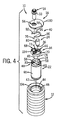
図3及び4は、図2の溶出システム10の底及び上から見た分解斜視図であり、種々の構成部品に対する位置合せアダプタ34と補足位置合せアダプタ40の位置合せ機能を示す。矢印42で示すように、放射性同位体発生器22は、上部開口44を通って補助シールド12の円筒凹部(receptacle)46に降下され、これにより当該放射性同位体発生器22の上部48が上方に上部開口44に向かって面する。図3に示すように、放射性同位体発生器22は、該放射性同位体発生器22の補助シールド12への降下を促進するために、フレキシブルハンドル50のような適切なハンドルを有する。図4に示さないが、フレキシブルハンドル50は、補助シールド12に完全に降下すると、シール放射性同位体発生器22の上部48の領域に一般に敷設される。放射性同位体発生器22を降下する前後に、位置合せアダプタ34は放射性同位体発生器22の上部48と関連させてもよい(例えば、嵌合させる)。図5は、補助シールド12の円筒凹部46の内側に配置された位置合せアダプタを外した放射性同位体発生器22の上から見た斜視図である。   3 and 4 are exploded perspective views from the bottom and top of the elution system 10 of FIG. 2, showing the alignment function of the alignment adapter 34 and the supplemental alignment adapter 40 for various components. As indicated by the arrow 42, the radioisotope generator 22 is lowered through the top opening 44 into the cylindrical receptacle 46 of the auxiliary shield 12, thereby causing the top 48 of the radioisotope generator 22 to move upward. Facing toward the upper opening 44. As shown in FIG. 3, the radioisotope generator 22 has a suitable handle, such as a flexible handle 50, to facilitate the descent of the radioisotope generator 22 to the auxiliary shield 12. Although not shown in FIG. 4, the flexible handle 50 is generally laid in the region of the upper portion 48 of the seal radioisotope generator 22 when fully lowered to the auxiliary shield 12. Before and after the radioisotope generator 22 is lowered, the alignment adapter 34 may be associated with (eg, mated with) the upper portion 48 of the radioisotope generator 22. FIG. 5 is a top perspective view of the radioisotope generator 22 with the alignment adapter disposed inside the cylindrical recess 46 of the auxiliary shield 12 removed.

図6,7,8,9に示された位置合せアダプタ34を図3,4に示す溶出システム10とともに参照すると、位置合せアダプタ34の底側52は、複数の位置合せタブ、例えば複数の湾曲タブ54と1組の扁平対向タブ56を有する。位置合せアダプタの位置合せタブは、放射性同位体発生器22の上部48の1又は複数の特徴に比較的密に係合し又は嵌合するように使用される。例えば、湾曲及び扁平タブ54,56は、放射性同位体発生器22の上部48の湾曲側58と扁平側60と比較的密着して係合又は嵌合するように使用してもよい。タブ54,56と上部48の間の比較的小さな隙間を考慮して、位置合せアダプタ34は放射性同位体発生器22に対して比較的強固に固定され平衡を保たれている。図示しないが、これらのタブ54,56、該タブ54,56間の溝、開口及び凹部、位置合せアダプタ34の底側52は、放射性同位体発生器22のフレキシブルハンドル50の貯蔵空間を提供する。この貯蔵空間は、フレキシブルハンドル50が位置合せアダプタ34と放射性同位体発生器22の間の望ましい(例えば平衡のとれた)嵌合と干渉する可能性を減少する。   Referring to the alignment adapter 34 shown in FIGS. 6, 7, 8, and 9 with the elution system 10 shown in FIGS. 3 and 4, the bottom side 52 of the alignment adapter 34 has a plurality of alignment tabs, such as a plurality of curves. It has a tab 54 and a pair of flat opposing tabs 56. The alignment tab of the alignment adapter is used to engage or fit relatively tightly with one or more features of the top 48 of the radioisotope generator 22. For example, the curved and flat tabs 54, 56 may be used to engage or fit relatively closely with the curved side 58 and the flat side 60 of the top 48 of the radioisotope generator 22. In view of the relatively small gap between the tabs 54, 56 and the upper portion 48, the alignment adapter 34 is relatively firmly fixed and balanced with respect to the radioisotope generator 22. Although not shown, these tabs 54, 56, the grooves, openings and recesses between the tabs 54, 56, and the bottom side 52 of the alignment adapter 34 provide storage space for the flexible handle 50 of the radioisotope generator 22. . This storage space reduces the possibility that the flexible handle 50 will interfere with the desired (eg, balanced) fit between the alignment adapter 34 and the radioisotope generator 22.

図3,6,8に示すように、位置合せアダプタ34の底側52は、全体的に湾曲し、又は部分的に円筒形の外側壁62を有していてもよい。この外側壁62は、補助シールド12の凹部46の少なくとも一部とほぼ同様の形状と寸法を示してもよい。これらのほぼ同様の形状と寸法を考慮して、円筒形の外側壁62は、補助シールド12の円筒形凹部46内に比較的ぴったりと嵌合すると言ってもよい。このように、位置合せアダプタ34は、少なくとも1つの点で、補助シールド12内の放射性同位体発生器22の上部48と全体的に一致し、密に嵌合し、取り外し可能に保持する。位置合せアダプタ34は補助シールド12の凹部46にほぼ類似する形状と寸法を有する外側壁62を有するように示されているが、他の実施形態の位置合せアダプタ34は、発生器に配置したときに、発生器を収容する補助シールドに対して発生器の所望部分を維持するのを促進し、又は少なくとも支援するような他の任意のデザインの外側壁62を有していてもよい。   
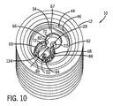
As shown in FIGS. 3, 6, and 8, the bottom side 52 of the alignment adapter 34 may be generally curved or have a partially cylindrical outer wall 62. The outer wall 62 may have substantially the same shape and size as at least a portion of the recess 46 of the auxiliary shield 12. In view of these substantially similar shapes and dimensions, it may be said that the cylindrical outer wall 62 fits relatively tightly within the cylindrical recess 46 of the auxiliary shield 12. In this way, the alignment adapter 34 is generally coincident with the upper portion 48 of the radioisotope generator 22 in the auxiliary shield 12 at least at one point, and is closely fitted and removably retained. While the alignment adapter 34 is shown having an outer wall 62 having a shape and dimensions that are generally similar to the recess 46 of the auxiliary shield 12, other embodiments of the alignment adapter 34 are shown when placed in the generator. In addition, it may have an outer wall 62 of any other design that facilitates or at least assists in maintaining the desired portion of the generator relative to the auxiliary shield that houses the generator.

図5を参照すると、放射性同位体発生器22の円筒外装65と補助シールド12の円筒凹部46の間に、位置合せアダプタ34の無い隙間64が存在する。図10に転じると、位置合せアダプタ34は、発生器22が補助シールド12に設置される前又は後に、放射性同位体発生器22の上部48に配置されてもよい。図10に示すように、位置合せアダプタ34の円筒外側壁62は、円筒凹部46の内側に比較的密接に嵌合し、これにより放射性同位体発止液22の上部48にある放射性同位体発生器22と円筒凹部46の間の隙間64を有効に防いでいる。したがって、位置合せアダプタ34は、補助シールド12に対する発生器(例えば、その入口及び出口の中空針28,30)の適切な位置合せと位置決めを促進し維持するのに利用されている。   Referring to FIG. 5, a gap 64 without the alignment adapter 34 exists between the cylindrical sheathing 65 of the radioisotope generator 22 and the cylindrical recess 46 of the auxiliary shield 12. Turning to FIG. 10, the alignment adapter 34 may be placed on the upper portion 48 of the radioisotope generator 22 before or after the generator 22 is installed on the auxiliary shield 12. As shown in FIG. 10, the cylindrical outer wall 62 of the alignment adapter 34 fits relatively closely inside the cylindrical recess 46 so that the radioisotope generation at the top 48 of the radioisotope stop solution 22 is achieved. The gap 64 between the vessel 22 and the cylindrical recess 46 is effectively prevented. Accordingly, the alignment adapter 34 is utilized to facilitate and maintain proper alignment and positioning of the generator (eg, its inlet and outlet hollow needles 28, 30) relative to the auxiliary shield 12.

図3,4,6,8,9に示すように、位置合せアダプタ34は、第1容器位置合せ通路(例えば下部通路)66と第2容器位置合せ通路(例えば、上部突出通路)68を有する。これらの通路は、66,68は、任意の適切な形状/設計を示していてもよい。例えば、通路66,68は、比較的小さな隙間をもって容器24及び溶出アセンブリ14を受け入れるためにほぼ円筒形の内面70,72を有するように示されている。図10に示すように、位置合せアダプタ34は、円筒凹部46と放射性同位体発生器22に密着して嵌合し(例えば、ぴったり接触し)、これにより通路66,68は入口及び出口の中空針28,30の上に強固に配置される。さらに、それぞれの通路66,68の円筒形内面70,72は、それぞれ入口及び出口の中空針28,30に対して芯出しされていることが好ましい(ただし、必ずしも常にではない)。この方法では、図3,4に示すように、位置合せアダプタ34は、技術者が容器24と溶出アセンブリ14をそれぞれ中心線74,76により示すように中空針28,30に向かって(中空針に向かって真っ直ぐに、芯出しされるように)所望の方法で案内する可能性を増加する。したがって、位置合せアダプタ34は、要素間の望まれない隙間及び遊びを有効に防ぎ、これにより容器24及び溶出アセンブリ14の中空針28,30に対する望ましくない傾斜及び/又は不一致の可能性を実質的に減少する。図示された通路66,68の入口通路は、溶離剤容器24と溶出アセンブリ14の初期挿入を容易にするために、面取り67,69を有している。これらの面取り67,69は、少なくともこの点に関して、容器24と溶出アセンブリ14が位置合せアダプタ34に対して初期に不一致であっても、容器24と溶出アセンブリ14の対応する通路66,68への適切な進入を容易にするのに利用される。重ねて言うが、容器24と溶出アセンブリ14の通路66,68内の密着嵌合は、容器24と溶出アセンブリ14が中空針28,30と所望の方向と位置(例えば、中心線74,76に沿って真っ直ぐで芯出しされた方向)で係脱する可能性を増加する。   As shown in FIGS. 3, 4, 6, 8, and 9, the alignment adapter 34 includes a first container alignment passage (for example, a lower passage) 66 and a second container alignment passage (for example, an upper protruding passage) 68. . These passages 66, 68 may indicate any suitable shape / design. For example, the passages 66, 68 are shown having generally cylindrical inner surfaces 70, 72 for receiving the container 24 and elution assembly 14 with a relatively small gap. As shown in FIG. 10, the alignment adapter 34 fits closely into the cylindrical recess 46 and the radioisotope generator 22 (eg, in close contact) so that the passages 66, 68 are hollow at the inlet and outlet. It is firmly arranged on the needles 28 and 30. Further, the cylindrical inner surfaces 70, 72 of the respective passages 66, 68 are preferably centered (but not always) with respect to the inlet and outlet hollow needles 28, 30, respectively. In this method, as shown in FIGS. 3 and 4, the alignment adapter 34 is moved by the technician toward the hollow needles 28, 30 as indicated by centerlines 74, 76, respectively, of the container 24 and the elution assembly 14 (hollow needles). Increases the possibility of guiding in the desired way (to be centered straight on). Accordingly, the alignment adapter 34 effectively prevents unwanted gaps and play between the elements, thereby substantially eliminating the possibility of undesirable tilting and / or mismatching of the container 24 and elution assembly 14 with respect to the hollow needles 28,30. To decrease. The illustrated inlet passages 66, 68 have chamfers 67, 69 to facilitate initial insertion of the eluent container 24 and elution assembly 14. These chamfers 67, 69, at least in this regard, even if the container 24 and elution assembly 14 are initially inconsistent with the alignment adapter 34, will lead to corresponding passages 66, 68 in the container 24 and elution assembly 14. Used to facilitate proper entry. Again, the close fit within the passages 66, 68 of the container 24 and the elution assembly 14 is such that the container 24 and the elution assembly 14 are aligned with the hollow needles 28, 30 in the desired direction and position (eg, centerlines 74, 76). Increase the possibility of engaging and disengaging in a straight and centered direction).

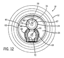
図11は、図10の溶出システムの側面断面図であり、さらに補助シールド12の円筒凹部46の中に配置された位置合せアダプタと放射性同位体発生器22に対して分解された溶離剤容器24を示す。1点鎖線78で示すように、溶離剤容器24の外面80は第1容器位置合せ通路66の内面70と密着して嵌合するような形状と寸法を有している。溶離剤容器24と第1容器位置合せ通路66の間の比較的密着して嵌合し又は遊びの少ないことにより、位置合せアダプタ34は、挿入及び取外し中に、入口中空針28に対する溶離剤容器24(及びその端部36)の傾斜、横ずれ、全体的不一致の可能性が減少する。図示された実施形態では、位置合せアダプタ34によりユーザは比較的真っ直ぐな方向に部品を案内し一致させることができるので、入口中空針28は、端部36のほぼ中心位置で、ほぼ真っ直ぐな方向に溶離剤容器24の端部36から進入し分離する。図示するように、溶離剤容器24の端部36と入口中空針28は、中心線74に沿って(例えばほぼ平行に)位置合せされる。図12は図11の溶出システム10の上面図であり、位置合せアダプタ34の第1容器位置合せ通路66と放射性同位体発生器22の入口中空針28の上に芯出しされた溶離剤容器24を示している。   FIG. 11 is a side cross-sectional view of the elution system of FIG. 10 and further shows the eluent container 24 disassembled relative to the alignment adapter and radioisotope generator 22 disposed in the cylindrical recess 46 of the auxiliary shield 12. Indicates. As indicated by an alternate long and short dash line 78, the outer surface 80 of the eluent container 24 has a shape and a size such that the outer surface 80 closely fits with the inner surface 70 of the first container alignment passage 66. Due to the relatively close fit or less play between the eluent container 24 and the first container alignment passage 66, the alignment adapter 34 can be attached to and removed from the inlet hollow needle 28 during insertion and removal. 24 (and its end 36) is less likely to be tilted, laterally offset, or totally inconsistent. In the illustrated embodiment, the alignment adapter 34 allows the user to guide and align the parts in a relatively straight direction so that the inlet hollow needle 28 is in a generally straight direction at a substantially central location of the end 36. To enter and separate from the end 36 of the eluent container 24. As shown, the end 36 of the eluent container 24 and the inlet hollow needle 28 are aligned along a centerline 74 (eg, substantially parallel). FIG. 12 is a top view of the elution system 10 of FIG. 11, with the eluent container 24 centered over the first container alignment passage 66 of the alignment adapter 34 and the inlet hollow needle 28 of the radioisotope generator 22. Is shown.

図10を参照すると、位置合せアダプタ34は、第2容器位置合せ通路68のC形形状84により少なくとも部分的に形成された溶離剤覗き窓82を有する。溶離剤覗き窓82は、第1容器位置合せ通路66に隣接するC形形状84の開口端に配置されている。図6に示すように、溶離剤覗き窓82は、第1,第2容器位置合せ通路66,68間に延びる開口、通路、又はスロットとして特徴付けられている。図10に図示しないが、溶離剤容器24が入口中空針28と係合して第1容器位置合せ通路66内に配置されれば、ユーザは溶離剤容器24内の溶離剤のレベルを矢印86で示すように溶離剤覗き窓82を通して見ることができる。以下にさらに詳細に説明するように、ユーザは、少なくともいくつかの実施形態で、蓋18が位置合せアダプタ34と補助シールド12の上に配置されたときに、覗き窓82を通して溶離剤レベルを見ることができる。覗き窓を有する位置合せアダプタの実施形態では、ユーザは、溶出システム10を完全に分解することなく、溶離剤容器24内に残っている溶離剤のレベルを少なくとも概略的に決定することができる。適切な覗き窓の実施形態を説明したが、他の位置合せアダプタは覗き窓として、多くの他の適切な設計のうちいずれかを有していてもよい。   Referring to FIG. 10, the alignment adapter 34 has an eluent viewing window 82 formed at least in part by a C-shaped 84 of the second container alignment passage 68. The eluent viewing window 82 is disposed at the open end of the C-shape 84 adjacent to the first container alignment passage 66. As shown in FIG. 6, the eluent viewing window 82 is characterized as an opening, passage or slot extending between the first and second container alignment passages 66,68. Although not shown in FIG. 10, if the eluent container 24 engages the inlet hollow needle 28 and is positioned in the first container alignment passage 66, the user can indicate the level of eluent in the eluent container 24 with the arrow 86. As seen through the eluent viewing window 82. As described in further detail below, the user views the eluent level through the viewing window 82 when the lid 18 is positioned over the alignment adapter 34 and the auxiliary shield 12 in at least some embodiments. be able to. In an alignment adapter embodiment having a viewing window, the user can at least approximately determine the level of eluent remaining in the eluent container 24 without completely disassembling the elution system 10. While suitable viewing window embodiments have been described, other alignment adapters may have any of a number of other suitable designs as viewing windows.

溶離剤覗き窓82に加えて、図10の位置合せアダプタ34は、第2容器位置合せ通路68の外面に波状グリップ88を有する。波状グリップ88は第2容器位置合せ通路68の外面に形成された一連の細長い溝として示されているが、ここの「波状グリップ」は、ユーザの位置合せアダプタ34の把持及び/又は保持を促進するように設けられた任意の面の特徴及び/又はテクスチャリング(texturing)をいう。この波形グリップは、少なくとも1つの点については、放射性同位体22と補助シールド12に対する位置合せアダプタ34の挿入及び取出しを少なくとも大まかに容易にするのに利用される。さらに、第2容器位置合せ通路68の突出した性質は、ユーザが(例えば、位置合せアダプタと発生器の相互接続及び/又は分離中に)放射性同位体発生器22上の中空針28,30の1つに接触する可能性を減少する。   In addition to the eluent viewing window 82, the alignment adapter 34 of FIG. 10 has a wavy grip 88 on the outer surface of the second container alignment passage 68. Although the wavy grip 88 is shown as a series of elongated grooves formed in the outer surface of the second container alignment passage 68, the “wavy grip” herein facilitates gripping and / or holding of the user's alignment adapter 34. Any surface feature and / or texturing provided to do so. This corrugated grip is utilized to at least roughly facilitate the insertion and removal of the alignment adapter 34 relative to the radioisotope 22 and the auxiliary shield 12 for at least one point. Further, the protruding nature of the second container alignment passage 68 allows the user to adjust the hollow needles 28, 30 on the radioisotope generator 22 (e.g., during the interconnection and / or separation of the alignment adapter and the generator). Reduce the chance of touching one.

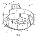
図13の蓋18を見るとともに、図3,4の分解された溶出システムを参照すると、補足位置合せアダプタ40は蓋18の下側90に付着され又は大まかに固定されている。図示しないが、いくつかの実施形態は、蓋18と一体の補足位置合せアダプタ(又は少なくともその一部)を含む。補足位置合せアダプタ40は、蓋18を貫通する組立通路94の回りにほぼ対称に配置された対向内側面92を有する。これらの対向内側面92は、位置合せアダプタ34の第1容器位置合せ通路68と溶離剤容器24の円筒形状外面80の回りに嵌合するようにほぼ湾曲形状を有する。第2容器位置合せ通路68と溶離剤容器24は、蓋18が補助シールド12と適切に位置合わせされ着座されたときに、補足位置合せアダプタ40内に設置され得る。   Looking at the lid 18 of FIG. 13 and referring to the exploded elution system of FIGS. 3 and 4, the supplemental alignment adapter 40 is attached or loosely secured to the lower side 90 of the lid 18. Although not shown, some embodiments include a supplemental alignment adapter (or at least a portion thereof) integral with the lid 18. The supplemental alignment adapter 40 has opposed inner surfaces 92 that are arranged generally symmetrically around an assembly passage 94 that passes through the lid 18. These opposing inner surfaces 92 have a generally curved shape so as to fit around the first container alignment passage 68 of the alignment adapter 34 and the cylindrical outer surface 80 of the eluent container 24. The second container alignment passage 68 and the eluent container 24 may be installed in the supplemental alignment adapter 40 when the lid 18 is properly aligned and seated with the auxiliary shield 12.

図13の補足位置合せアダプタ40は、ほぼC形状又は部分的に円筒形の外面96を有するほぼC字形ディスク構造95として特徴付けられ、これは補助シールド12の円筒凹部46内の位置合わせと比較的密着した嵌合を容易にする。蓋18は、1対の対向扁平側面98と1対の対向湾曲側面100を有し、補助シールと12に対する蓋18の挿入と取り出しを容易にしている。例えば、対向扁平側面98は、ユーザが補助シールド12に対して挿入及び取り出し中に蓋18を把持するための1対の対向凹部又は穴を有していてもよい。対向湾曲側面100は、全体的にテーパ(例えば、傾斜、楔形、部分的円錐等)が付けられ、補助シールド12の上部開口44内の密着嵌合芯出し位置に向かって蓋18を案内する。   The supplemental alignment adapter 40 of FIG. 13 is characterized as a generally C-shaped disk structure 95 having a generally C-shaped or partially cylindrical outer surface 96, which is compared to the alignment in the cylindrical recess 46 of the auxiliary shield 12. Facilitate close fitting. The lid 18 has a pair of opposed flat side surfaces 98 and a pair of opposed curved side surfaces 100 to facilitate insertion and removal of the lid 18 with respect to the auxiliary seal 12. For example, the opposed flat side surface 98 may have a pair of opposed recesses or holes for the user to grip the lid 18 during insertion and removal from the auxiliary shield 12. The opposed curved side surface 100 is generally tapered (e.g., inclined, wedge-shaped, partially conical, etc.) and guides the lid 18 toward a close fitting centering position within the upper opening 44 of the auxiliary shield 12.

図14を参照すると、図11と12の溶出システム10の上部斜視図であり、補助シールド12の上部開口44の上に配置されそれを覆う図1−4、11の蓋18を示す。図示するように、蓋18に形成された組立通路94は、位置合せアダプタ34の第2容器位置合せ通路68とほぼ一直線に合わせられている。位置合せアダプタ34と補足位置合せアダプタ40の利用により達成されるこの位置では、矢印86で示すように、溶離剤容器24は蓋18の通路94と位置合せアダプタ34の覗き窓82を通して見ることができる。したがって、ユーザは蓋18を取り外すことなく、溶離剤容器24内の溶離剤レベルを決定することができる。   Referring to FIG. 14, it is a top perspective view of the elution system 10 of FIGS. 11 and 12, showing the lid 18 of FIGS. 1-4, 11 positioned over and covering the upper opening 44 of the auxiliary shield 12. As shown, the assembly passage 94 formed in the lid 18 is substantially aligned with the second container alignment passage 68 of the alignment adapter 34. In this position, which is achieved through the use of alignment adapter 34 and supplemental alignment adapter 40, eluent container 24 can be viewed through passage 94 in lid 18 and viewing window 82 in alignment adapter 34, as indicated by arrow 86. it can. Thus, the user can determine the eluent level in the eluent container 24 without removing the lid 18.

図14にさらに示すように、蓋18の対向平坦側面98は、蓋18と補助シールド12の上部内面との間に小さな凹部又は開口102を残している。図示された開口102は、対向する円の切片の形を有している。これらの開口102によりユーザは蓋18の対向する扁平側面98を把持し、補助シールド12に対して挿入し取り外すことができる。蓋18の他の実施形態は、蓋18の側面に対して多くの他の適切な設計の何れかとし、ユーザが蓋を取り外すのを容易にする蓋と補助シールド12の間の1以上の少なくとも部分的な開口を提供してもよい。   As further shown in FIG. 14, the opposing flat side surface 98 of the lid 18 leaves a small recess or opening 102 between the lid 18 and the upper inner surface of the auxiliary shield 12. The illustrated opening 102 has the shape of an opposing circular segment. With these openings 102, the user can hold the opposing flat side surface 98 of the lid 18, and can insert and remove it from the auxiliary shield 12. Other embodiments of the lid 18 are any of a number of other suitable designs for the sides of the lid 18 and include at least one or more between the lid and the auxiliary shield 12 that facilitates the user to remove the lid. Partial openings may be provided.

図14の補助シールド12は、テーパが付けられ又は傾斜した円筒形内面104を有し、それは補助シールド12の凹部46を被覆し及び/又は露出する間に蓋18の対向する湾曲側面100とスライド可能に接触する。蓋18と補助シールド12の内面104の間の接触は、凹部46の上部開口44の上の所望の(例えば密着して嵌合し位置合せされた)位置に向かって蓋18を案内するよう機能する。   The auxiliary shield 12 of FIG. 14 has a tapered or inclined cylindrical inner surface 104 that slides against the opposing curved side surface 100 of the lid 18 while covering and / or exposing the recess 46 of the auxiliary shield 12. Contact possible. Contact between the lid 18 and the inner surface 104 of the auxiliary shield 12 functions to guide the lid 18 toward a desired (eg, closely fitted and aligned) position above the upper opening 44 of the recess 46. To do.

補足位置合せアダプタ40のC形状の外面96は、凹部46の内面と接触する傾向があり、これにより凹部46に対する蓋18の適切な位置合わせを促進する。前述したように、補足位置合せアダプタ40の対向する内側面92は、位置合せアダプタ34の第2容器位置合せ通路68と溶離剤容器24の形状と寸法に少なくとも概略的に嵌合する第2領域を有する。設置している間に、蓋18は、補足位置合せアダプタ40の対向する内側面92が第2容器位置合せ通路68のC字形傾向84と溶離剤容器24と適切に一致するまで、完全に降下しないし、着座しない。このようにして、補足位置合せアダプタ40は、蓋18の組立通路94が位置合せアダプタ34の第2容器位置合せ通路68と、すなわち、位置合せアダプタ34の下方で放射性同位体発生器22に配置された出口中空針30と、適切に一致する可能性を増加すると言える。   The C-shaped outer surface 96 of the supplemental alignment adapter 40 tends to contact the inner surface of the recess 46, thereby facilitating proper alignment of the lid 18 with respect to the recess 46. As described above, the opposing inner surface 92 of the supplemental alignment adapter 40 has a second region that fits at least approximately the shape and dimensions of the second container alignment passage 68 of the alignment adapter 34 and the eluent container 24. Have During installation, the lid 18 is fully lowered until the opposing inner surface 92 of the supplemental alignment adapter 40 is properly aligned with the eluent container 24 and the C-shaped trend 84 of the second container alignment passage 68. Do not sit down. In this way, the supplemental alignment adapter 40 is arranged in the radioisotope generator 22 so that the assembly passage 94 of the lid 18 is in the second container alignment passage 68 of the alignment adapter 34, that is, below the alignment adapter 34. It can be said that there is an increased possibility of an appropriate match with the exit hollow needle 30 made.

図15は、位置合せアダプタ34と補足位置合せアダプタ40の間の相互作用を示すために補助シールド12を無くした図14の溶出システム10の底から見た部分斜視図である。図示するように、蓋18は、位置合せアダプタ34と補足位置合せアダプタ40の間の接触面を介して放射性同位体発生器22と一致する。例えば、補足位置合せアダプタ40の対向する内側面92は、位置合せアダプタ34の第2容器位置合せ通路68の外面の少なくとも一部と、蓋18が補助シールと12の開口に完全に着座している図示された形態のある溶離剤容器24の外面の少なくとも一部との回りに配置されている。蓋18の設置中に、蓋18の下側90にある補足位置合せアダプタ40は、凹部(例えば対向する内側面92の間)が第1容器位置合せ通路66及び溶離剤容器24と適切に一致するまで、蓋18を保持する機能を有する。適切に一致すると、補足位置合せアダプタ40の凹部により、ユーザは補助シールド12の開口44を覆い完全に着座するように蓋18を配置することができる。この位置合せ位置では、通路94は、第2容器位置合せ通路68と、位置合せアダプタ34の下方の放射性同位体発生器22に配置された出口中空針30とに適切に一致することが好ましい。   FIG. 15 is a partial perspective view from the bottom of the elution system 10 of FIG. 14 with the auxiliary shield 12 removed to show the interaction between the alignment adapter 34 and the supplemental alignment adapter 40. As shown, the lid 18 coincides with the radioisotope generator 22 via a contact surface between the alignment adapter 34 and the supplemental alignment adapter 40. For example, the opposing inner side surface 92 of the supplemental alignment adapter 40 may have at least a portion of the outer surface of the second container alignment passage 68 of the alignment adapter 34 and the lid 18 fully seated in the auxiliary seal and 12 opening. And is disposed about at least a portion of the outer surface of the eluent container 24 in the illustrated configuration. During installation of the lid 18, the supplemental alignment adapter 40 on the lower side 90 of the lid 18 has a recess (eg, between opposing inner surfaces 92) that is properly aligned with the first container alignment passage 66 and the eluent container 24. Until the lid 18 is held. When properly matched, the recess in the supplemental alignment adapter 40 allows the user to place the lid 18 over the opening 44 of the auxiliary shield 12 and fully seated. In this alignment position, the passage 94 preferably matches the second container alignment passage 68 and the exit hollow needle 30 located in the radioisotope generator 22 below the alignment adapter 34.

図16と図17は、図15の溶出システム10の部分断面側面図であり、出口中空針30の上のアセンブリ通路94を通って部分的に延びるシールされた溶出アセンブリ14を示す。矢印106で示すように、位置合せアダプタ34は、技術者が出口中空針30と溶出液容器26の中心線76に沿ってほぼ真っ直ぐな方向にシールされた溶出アセンブリ14を案内するのを支援する。シールされた溶出アセンブリ14の外面形状と寸法の少なくとも一部は、突出通路68の内面形状と寸法と密着して嵌合し、これによりアセンブリ14と突出通路68の間の隙間を実質的に最小にしている。この方法において、位置合せアダプタ34は、放射性同位体発生器22の外部中空針30に対するシールされた溶出アセンブリ14の挿入及び/又は取り出し中、溶出システム10の部品の不一致、傾斜、及び/又は損傷の可能性を減少する。図18はシールされた溶出アセンブリ14の斜視図であり、該溶出アセンブリ14は蓋18を通して補助シールド12に完全に挿入され、放射性同位体発生器22の外側中空針30と係合している。   16 and 17 are partial cross-sectional side views of the elution system 10 of FIG. 15 showing the sealed elution assembly 14 partially extending through the assembly passage 94 above the outlet hollow needle 30. As indicated by arrow 106, the alignment adapter 34 assists the technician in guiding the elution assembly 14 that is sealed in a substantially straight direction along the centerline 76 of the outlet hollow needle 30 and the eluate container 26. . At least a portion of the outer shape and dimensions of the sealed elution assembly 14 fit closely with the inner shape and dimensions of the protruding passage 68, thereby substantially minimizing the gap between the assembly 14 and the protruding passage 68. I have to. In this manner, the alignment adapter 34 may cause mismatching, tilting, and / or damage of components of the elution system 10 during insertion and / or removal of the sealed elution assembly 14 from the outer hollow needle 30 of the radioisotope generator 22. Reduce the possibility of FIG. 18 is a perspective view of the sealed elution assembly 14 that is fully inserted into the auxiliary shield 12 through the lid 18 and engages the outer hollow needle 30 of the radioisotope generator 22.

図19は、図16と17の溶出システム10の上から見た斜視図であり、通路94内に配置された(シールされた溶出アセンブリ14よりも)蓋プラグ108を示す。図示するように、蓋プラグ108は有効に通路94を閉塞し、放射線が(例えば補助シールド12の内側に配置された放射性同位体発生器22から)通路94を通って漏出する可能性を減少している。図示された蓋プラグ108は、プラグ108の本体112の頭部から延びる突出グリップ又はペグ110を有し、これによりユーザは通路94に挿入し及び通路94から取り出すために蓋プラグ108を容易に把持することができる。本体112の頭部は、第1弓形(例えば半円)外側壁又は形状114、第2弓形(例えば半円)外側壁又は形状116、及び中間屈曲外側壁又は部分118を有している。これらの形状114,116と屈曲部118は、通路94の形状120,122と屈曲部124と密着して嵌合し、これにより蓋18と溶出システム10の内側に配置された要素に対する蓋プラグ108の適切な位置合わせが促進される。蓋プラグ18は少なくとも部分的に鉛、及び/又は他の適切な放射線遮蔽材料で形成されている。   FIG. 19 is a top perspective view of the elution system 10 of FIGS. 16 and 17 showing the lid plug 108 disposed in the passage 94 (rather than the sealed elution assembly 14). As shown, the lid plug 108 effectively occludes the passageway 94 and reduces the likelihood that radiation will leak through the passageway 94 (eg, from a radioisotope generator 22 disposed inside the auxiliary shield 12). ing. The illustrated lid plug 108 has a protruding grip or peg 110 that extends from the head of the body 112 of the plug 108 so that the user can easily grasp the lid plug 108 for insertion and removal from the passage 94. can do. The head of the body 112 has a first arcuate (eg, semicircle) outer wall or shape 114, a second arcuate (eg, semicircle) outer wall or shape 116, and an intermediate bend outer wall or portion 118. These shapes 114, 116 and bend 118 are intimately engaged with shapes 120, 122 and bend 124 of passage 94, thereby closing lid plug 108 for lid 18 and elements located inside elution system 10. Proper alignment is promoted. The lid plug 18 is at least partially formed of lead and / or other suitable radiation shielding material.

図20は、図19の溶出システム10の部分的分解斜視図であり、蓋18から外された蓋プラグ108と補助シールド12の内側に配置された位置合せアダプタ34を示す。図示するように、蓋プラグ108は、本体112の中央部128の回りに配置された部分円筒形又はC形位置合せスリーブ126を有する。図示されたC形位置合せスリーブ126は、中央部128の回りに弾性的に嵌合することができるプラスチック材料又は他のフレキシブル材料で形成されている。C形位置合せスリーブ126は、本体112の大部分に沿って中央部128の厚さ又は径を有効に増加する。増加した寸法に関して、C形位置合せスリーブ126は、中央部128に密着して嵌合し、位置合せアダプタ34の第2容器位置合せ通路68の円筒形内面72の寸法になる。このようにして、C形位置合せスリーブ126は、位置合せアダプタ34に対する蓋プラグ108の挿入と取り出しの大部分の間に、蓋プラグ108と円筒形内面の間の比較的小さな隙間を促進する。例えば、C形位置合せスリーブ126は本体112の嵌合装着位置合せ部として形成されてもよい。   FIG. 20 is a partially exploded perspective view of the elution system 10 of FIG. 19, showing the lid plug 108 removed from the lid 18 and the alignment adapter 34 positioned inside the auxiliary shield 12. As shown, the lid plug 108 has a partially cylindrical or C-shaped alignment sleeve 126 disposed around the central portion 128 of the body 112. The illustrated C-shaped alignment sleeve 126 is formed of a plastic material or other flexible material that can be resiliently fitted around the central portion 128. The C-shaped alignment sleeve 126 effectively increases the thickness or diameter of the central portion 128 along most of the body 112. With respect to the increased dimensions, the C-shaped alignment sleeve 126 fits closely into the central portion 128 to the dimensions of the cylindrical inner surface 72 of the second container alignment passage 68 of the alignment adapter 34. In this way, the C-shaped alignment sleeve 126 facilitates a relatively small gap between the lid plug 108 and the cylindrical inner surface during most of the insertion and removal of the lid plug 108 from the alignment adapter 34. For example, the C-shaped alignment sleeve 126 may be formed as a fitting / mounting alignment portion of the main body 112.

さらに、図20の蓋プラグ108は、位置合せタブ132を有する半円筒形ベース130を含み、該円筒形ベース130は位置合せアダプタ34の第2容器位置合せ通路68にある矩形スロット又は溝134内に嵌合している。位置合せタブ132は、位置合せアダプタ34と放射性同位体発生器22に配置された出口中空針30に対する蓋プラグ108の適切な位置合わせを促進する。   Further, the lid plug 108 of FIG. 20 includes a semi-cylindrical base 130 having an alignment tab 132 that is within a rectangular slot or groove 134 in the second container alignment passage 68 of the alignment adapter 34. Is fitted. The alignment tab 132 facilitates proper alignment of the lid plug 108 with respect to the alignment adapter 34 and the exit hollow needle 30 located in the radioisotope generator 22.

図21は、図20の蓋プラグ108の底から見た分解斜視図であり、さらに無菌液容器136を図示している。無菌液容器136は凹部138の中央部128の内側に嵌合し、凹部138は半円筒形ベース130により実質的に覆われている。ベース130は、該ベース130を回転させて中央部128に配置されたラッチ又はタブ40と係合することで、中央部128に取り付けられている。図示された滅菌液容器136は滅菌液(例えばTechneStat(登録商標))を収容し、該滅菌液は中空針通路142を通してアクセスされる。ベース130はさらに、放射性同位体発生器22に配置された出口中空針30が滅菌液容器136に進入することを可能にする通路144を有する。蓋プラグ108が完全に溶出システム10に設置されると、出口中空針30は、ベース130の通路を通り、中空針通路142を経て、滅菌液容器136に延びて、これにより次の溶出システムが実行されるまで中空針が滅菌される可能性が増加する。   FIG. 21 is an exploded perspective view seen from the bottom of the lid plug 108 of FIG. 20 and further shows a sterile liquid container 136. The sterile liquid container 136 fits inside the central portion 128 of the recess 138, and the recess 138 is substantially covered by the semi-cylindrical base 130. The base 130 is attached to the central portion 128 by rotating the base 130 and engaging a latch or tab 40 located at the central portion 128. The illustrated sterilization liquid container 136 contains a sterilization liquid (eg, TechneStat®), which is accessed through the hollow needle passage 142. The base 130 further includes a passage 144 that allows the exit hollow needle 30 located in the radioisotope generator 22 to enter the sterilization fluid container 136. When the lid plug 108 is fully installed in the elution system 10, the outlet hollow needle 30 extends through the passage of the base 130, through the hollow needle passage 142 to the sterilization fluid container 136, thereby allowing the next elution system to pass. There is an increased likelihood that the hollow needle will be sterilized until run.

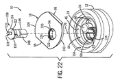
図22は、図19の溶出システム10の上から見た分解斜視図であり、蓋18と補助シールド12内の位置合せアダプタ34とから分解された代案の実施形態を示す。図示するように、図22のプラグ108は、半円筒形位置合せ構造146と、蓋プラグ108の長さの実質的部分に沿って配置された突出ガイド部又は位置合せレール148を有する。この半円筒形位置合せ構造146と位置合せレール148の形状と寸法は、円筒形内面72と、位置合せアダプタ34の第2容器位置合せ通路68の矩形のスロット又は溝134とに密接して嵌合する。半円筒位置合せ構造146と第2容器位置合せ通路68の円筒形内面72との間の比較的小さな隙間は、蓋プラグ108が出口中空針30に対して傾斜又はずれることなく、位置合せアダプタ34を通って真っ直ぐに移動するのを促進する。さらに、位置合せレール148は、矩形のスロット又は溝134に沿ってスライドするように設計され、これにより位置合せアダプタ34に対する蓋プラグ108の適切な位置合せが促進される。これらの理由のために、半円筒形位置合せ構造146及び/又は位置合せレール148は、本体112の嵌合装着位置合せ部(fitted-mounting alignment portion)として形成されてもよい。   FIG. 22 is an exploded perspective view from above of the elution system 10 of FIG. 19 and shows an alternative embodiment disassembled from the lid 18 and the alignment adapter 34 in the auxiliary shield 12. As shown, the plug 108 of FIG. 22 has a semi-cylindrical alignment structure 146 and protruding guides or alignment rails 148 disposed along a substantial portion of the length of the lid plug 108. The shape and dimensions of the semi-cylindrical alignment structure 146 and alignment rail 148 fit closely into the cylindrical inner surface 72 and the rectangular slot or groove 134 of the second container alignment passage 68 of the alignment adapter 34. Match. The relatively small gap between the semi-cylindrical alignment structure 146 and the cylindrical inner surface 72 of the second container alignment passage 68 prevents the alignment plug 34 from tilting or shifting with respect to the outlet hollow needle 30. Facilitates moving straight through. Further, the alignment rail 148 is designed to slide along a rectangular slot or groove 134 to facilitate proper alignment of the lid plug 108 with respect to the alignment adapter 34. For these reasons, the semi-cylindrical alignment structure 146 and / or alignment rail 148 may be formed as a fitted-mounting alignment portion of the body 112.

図23は、図22の蓋プラグ108の底から見た分解斜視図であり、さらに滅菌液容器136を示す。図示するように、滅菌液容器136は凹部138の中央部128内に嵌合している。半円筒形位置合せ構造146は、中央部128の上に延び、回転してラッチ又はタブ140に掛止している。図20と21のベース130と同様に、半円筒形位置合せ構造146は、通路150を有し、滅菌液容器136の中空針通路142に対する出口中空針30の挿入と取り外しを容易にしている。しかしながら、図示された半円筒形位置合せ構造146は、中央部128全体に沿って延びている。このように、図20と21の実施形態と対照的に、半円筒形位置合せ構造146は、C形位置合せスリーブ126とベース130を単一構造に一体化している。重ねて言うが、この半円筒形位置合せ構造146の形状と寸法は、位置合せアダプタ34の第2容器位置合せ通路68の形状と寸法に対して密着して嵌合し位置合わせされる。この密着嵌合と位置合わせに関して、半円筒形位置合せ構造146は、位置合せアダプタ34と放射性同位体発生器22の出口中空針30に対する蓋プラグ108の位置合わせを容易にする。   FIG. 23 is an exploded perspective view seen from the bottom of the lid plug 108 of FIG. 22 and further shows a sterilizing liquid container 136. As shown in the figure, the sterilizing liquid container 136 is fitted in the central portion 128 of the recess 138. The semi-cylindrical alignment structure 146 extends over the central portion 128 and rotates to latch on the latch or tab 140. Similar to the base 130 of FIGS. 20 and 21, the semi-cylindrical alignment structure 146 has a passage 150 to facilitate insertion and removal of the outlet hollow needle 30 from the hollow needle passage 142 of the sterilization fluid container 136. However, the illustrated semi-cylindrical alignment structure 146 extends along the entire central portion 128. Thus, in contrast to the embodiment of FIGS. 20 and 21, the semi-cylindrical alignment structure 146 integrates the C-shaped alignment sleeve 126 and the base 130 into a single structure. Again, the shape and size of the semi-cylindrical alignment structure 146 are closely fitted and aligned with the shape and size of the second container alignment passage 68 of the alignment adapter 34. With respect to this tight fit and alignment, the semi-cylindrical alignment structure 146 facilitates alignment of the lid plug 108 with the alignment adapter 34 and the exit hollow needle 30 of the radioisotope generator 22.

図24は、図19の蓋プラグ108の他の代案の実施形態の底から見た斜視図である。図24の蓋プラグ108は滅菌液容器136を横方向154に挿入し取り出すための横アクセス凹部152を有する。図示するように、蓋プラグ108の本体112は、本体112の長さの実質的部分に沿って円筒形外形156を有する。この円筒形外形156の寸法は、位置合せアダプタ34の第2容器位置合せ通路68の円筒形内面72の寸法と密着して嵌合する。したがって、円筒形外形156は、位置合せアダプタ34に対する蓋プラグ108の挿入と取り出しの少なくとも大部分の間に、蓋プラグ108と第2容器位置合せ通路68の円筒形内面72との間の隙間を実質的に最小にする。これらのために、円筒形外形156は、本体112の嵌合装着位置合せ部として形成されてもよい。さらに、図示された蓋プラグ108は1ピース構造であり、他の設計に関連する多部品と複雑性を排除している。ある実施形態では、横アクセス凹部152は、滅菌液容器136を本体112内のある位置に取り外し可能に固定するために、ラッチ、スナップ嵌合機構、摩擦嵌合機構、及び/又は他の適切な機構を有している。   FIG. 24 is a perspective view from the bottom of another alternative embodiment of the lid plug 108 of FIG. 24 has a lateral access recess 152 for inserting and removing the sterilizing liquid container 136 in the lateral direction 154. As shown, the body 112 of the lid plug 108 has a cylindrical profile 156 along a substantial portion of the length of the body 112. The size of the cylindrical outer shape 156 is closely fitted to the size of the cylindrical inner surface 72 of the second container alignment passage 68 of the alignment adapter 34. Accordingly, the cylindrical profile 156 provides a clearance between the lid plug 108 and the cylindrical inner surface 72 of the second container alignment passage 68 during at least the majority of insertion and removal of the lid plug 108 from the alignment adapter 34. Minimize substantially. For these reasons, the cylindrical outer shape 156 may be formed as a fitting and mounting position aligning portion of the main body 112. Further, the illustrated lid plug 108 is a one-piece construction, eliminating the multi-part and complexity associated with other designs. In certain embodiments, the lateral access recess 152 can be latched, snap-fit, friction-fit, and / or other suitable to removably secure the sterilization fluid container 136 at a location within the body 112. It has a mechanism.

横アクセス凹部152内に挿入するとき、滅菌液容器136は、中空針通路142が蓋プラグ108の端部の通路158と一致するように、芯合わせされる。蓋プラグ108はまた、横アクセス凹部152から反対側に取り出しアクセス穴160を有する。この取り出しアクセス穴160によりユーザは滅菌液容器136を装着位置から外側に横アクセス凹部152内に押すことができる。このように、横アクセス凹部152と取り出しアクセス穴160は、好ましくは蓋プラグ108の部品を組立又は分解することなく、滅菌液容器136の容易な挿入と取り出しを促進する。   When inserted into the lateral access recess 152, the sterilization fluid container 136 is centered such that the hollow needle passage 142 coincides with the passage 158 at the end of the lid plug 108. The lid plug 108 also has a withdrawal access hole 160 on the opposite side from the lateral access recess 152. The take-out access hole 160 allows the user to push the sterilizing liquid container 136 outward from the mounting position into the lateral access recess 152. Thus, the lateral access recess 152 and the removal access hole 160 facilitate the easy insertion and removal of the sterilization fluid container 136, preferably without assembling or disassembling the lid plug 108 components.

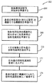
図25は、図1−24を参照して説明した溶出システム10により生成される放射性同位体を利用する例示的な核医療プロセスを示すフローチャートである。図示するように、プロセス162は、ブロック164で核医療用の放射性同位体を準備することにより開始する。例えば、ブロック164は、前に詳細に図示し説明した放射性同位体発生器22からのテクネチウム−99mを溶出することを含んでいてもよい。ブロック166では、プロセス162は、患者の特定部分、例えば器官に対する放射性同位体をターゲットにするように適合された標識剤(例えば、エピトープ又は他の適当な生物学的指向部分(biological directing moiety))を準備することによって開始する。ブロック168では、プロセス162は、放射性同位体を標識剤と組み合わせて核医療用の放射性薬剤を提供することによって開始する。ある実施形態では、放射性同位体は特定の器官又は組織に向かって集中する自然な傾向を有していてもよい。このために、放射性同位体は、如何なる補足標識剤も追加することのない放射性薬剤として特徴付けられる。ブロック170では、プロセス162は、1又はそれを超える投与量の放射性薬剤をシリンジ又は核医療施設又は病院で放射性薬剤を患者に投与するのに適した容器のような他の容器に抽出することで開始する。ブロック172では、プロセス162は、1投与量の放射性薬剤を患者に注入し、又は一般的に投与することにより開始する。予め選択された時間の後、プロセス162は、患者の器官又は組織に添付された放射性薬剤(ブロック174)を検出/造影することで開始する。例えば、ブロック174は、脳、心臓、肝臓、腫瘍、ガン組織、その他の種々の器官の組織又は疾患組織に配置された放射性薬剤を検出するために、ガンマカメラ又は他の放射線撮像装置を使用することを含む。   FIG. 25 is a flow chart illustrating an exemplary nuclear medical process utilizing radioisotopes generated by the elution system 10 described with reference to FIGS. 1-24. As shown, process 162 begins by preparing a radioisotope for nuclear medicine at block 164. For example, block 164 may include eluting technetium-99m from the radioisotope generator 22 shown and described in detail above. At block 166, the process 162 includes a labeling agent (eg, an epitope or other suitable biological directing moiety) adapted to target a specific part of the patient, eg, a radioisotope for an organ. Start by preparing. At block 168, the process 162 begins by combining a radioisotope with a labeling agent to provide a radiopharmaceutical for nuclear medicine. In certain embodiments, the radioisotope may have a natural tendency to concentrate towards a particular organ or tissue. To this end, the radioisotope is characterized as a radiopharmaceutical without the addition of any supplemental labeling agent. At block 170, the process 162 extracts one or more doses of the radiopharmaceutical into a syringe or other container, such as a container suitable for administering the radiopharmaceutical to the patient at a nuclear medical facility or hospital. Start. At block 172, the process 162 begins by injecting or generally administering a dose of radiopharmaceutical to the patient. After a preselected time, the process 162 begins with detecting / imaging the radiopharmaceutical (block 174) attached to the patient's organ or tissue. For example, block 174 uses a gamma camera or other radiation imaging device to detect radiopharmaceuticals placed in brain, heart, liver, tumor, cancer tissue, other various organ tissues or diseased tissue. Including that.

図26は、核医療分野で使用するために配置された放射性薬剤を有するシリンジを提供する例示的システム176のブロック図である。図示するように、システム176は、図1−24を参照して前に説明した放射性同位体溶出システム10を含む。システム176はまた、放射性同位体180(例えば、放射性同位体溶出システム10の使用により獲得されるテクネチウム−99m溶液)を標識剤182と組み合わせる機能を有する放射性薬剤生成システム178を含む。ある実施形態では、この放射性薬剤生成システム178は、「キット」(例えば、診断放射性薬剤の準備をするためのテクネスキャン(Technescan; 登録商標))として当業者に公知のものを言及し、又はこれを含んでいてもよい。重ねて言うが、標識剤は、特定の部分(例えば、器官、組織、腫瘍、癌等)に引き付けられ又は目標とされる種々の物質を含んでいてもよい。この結果、放射性同位体生成システム178は、ブロック184で示すように、放射性同位体180と標識剤182を含む放射性薬剤を生成し、又はそれを生成するのに利用してもよい。図示されたシステム176はまた、放射性薬剤をバイアル又はシリンジ188に抽出するのを容易にする放射性薬剤分注システム186を有していてもよい。ある実施形態では、システム176の種々の要素及び機能は放射性薬局内に配置され、該放射性薬局は核医療分野で使用する放射性薬剤を有するシリンジ188を準備する。例えば、シリンジ188を準備して、患者の診断又は治療に使用する医療施設に引き渡してもよい。   FIG. 26 is a block diagram of an exemplary system 176 that provides a syringe having a radiopharmaceutical arranged for use in the nuclear medicine field. As shown, the system 176 includes the radioisotope elution system 10 previously described with reference to FIGS. 1-24. The system 176 also includes a radiopharmaceutical production system 178 that has the function of combining a radioisotope 180 (eg, a technetium-99m solution obtained by use of the radioisotope elution system 10) with the labeling agent 182. In certain embodiments, the radiopharmaceutical production system 178 refers to or is known to those skilled in the art as a “kit” (eg, Technescan® for preparing diagnostic radiopharmaceuticals). May be included. Again, the labeling agent may include various substances that are attracted to or targeted to a particular part (eg, organ, tissue, tumor, cancer, etc.). As a result, the radioisotope generation system 178 may generate or be used to generate a radiopharmaceutical that includes the radioisotope 180 and the labeling agent 182 as indicated by block 184. The illustrated system 176 may also include a radiopharmaceutical dispensing system 186 that facilitates extracting the radiopharmaceutical into a vial or syringe 188. In certain embodiments, the various elements and functions of the system 176 are located within a radiopharmacy that provides a syringe 188 with a radiopharmaceutical for use in the nuclear medicine field. For example, the syringe 188 may be prepared and delivered to a medical facility used for patient diagnosis or treatment.

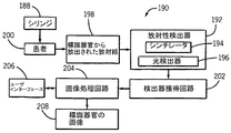
図27は、図26のシステム176を使用して提供される放射性薬剤のシリンジ188を利用する例示的な核医療撮像システム190のブロック図である。図示するように、核医療撮像システム190は、シンチレータ194と光検出器196を有する放射線検出器192を含む。患者200の標識器官から放出される放射線198に応じて、シンチレータ194は光を放出し、該光は光検出器196により検出され電気信号に変換される。図示しないが、撮像システム190は、放射線検出器192に向かって指向される放射線198を平行にするコリメータを含んでいてもよい。図示された撮像システム190はまた、検出器獲得回路202と画像処理回路204を有していてもよい。検出器獲得回路202は、放射線検出器192からの電気信号の獲得を全体的に制御する。画像処理回路204は、電子信号を処理し、検査プロトコルを実行する等に利用されてもよい。図示された撮像システム190はまた、画像処理回路204及び撮像システム190の他の要素とのユーザインターアクションを容易にするためにユーザインターフェース206を有する。この結果、撮像システム190は、患者200内の標識器官の画像208を生成する。重ねて言うが、前述した手順とその結果画像208は、図1−24に図示しこれらを参照して説明したように、溶出システム10により生成される放射性薬剤から直接利益を得る。   FIG. 27 is a block diagram of an exemplary nuclear medical imaging system 190 that utilizes a radiopharmaceutical syringe 188 provided using the system 176 of FIG. As shown, the nuclear medical imaging system 190 includes a radiation detector 192 having a scintillator 194 and a photodetector 196. In response to radiation 198 emitted from the labeled organ of patient 200, scintillator 194 emits light that is detected by photodetector 196 and converted to an electrical signal. Although not shown, the imaging system 190 may include a collimator that collimates the radiation 198 directed toward the radiation detector 192. The illustrated imaging system 190 may also include a detector acquisition circuit 202 and an image processing circuit 204. Detector acquisition circuit 202 generally controls the acquisition of electrical signals from radiation detector 192. The image processing circuit 204 may be used to process an electronic signal and execute an inspection protocol. The illustrated imaging system 190 also includes a user interface 206 to facilitate user interaction with the image processing circuit 204 and other elements of the imaging system 190. As a result, the imaging system 190 generates an image 208 of the marked organ within the patient 200. Again, the above-described procedure and resulting image 208 benefits directly from the radiopharmaceutical produced by the elution system 10, as shown and described with reference to FIGS. 1-24.

本発明は種々の修正と代案形態を受け入れる余地があるが、特定の実施形態を一例として示し、詳細に説明した。しかしながら、本発明は開示された特定の形態に限定されることを意図するものではないことを理解されるべきである。むしろ、本発明は、特許請求の範囲により規定された本発明の精神及び範囲内に含まれる全ての修正、均等物、代案を包含するものである。   While the invention is susceptible to various modifications and alternative forms, specific embodiments have been shown by way of example and described in detail. However, it should be understood that the invention is not intended to be limited to the particular forms disclosed. On the contrary, the invention is intended to cover all modifications, equivalents, and alternatives falling within the spirit and scope of the invention as defined by the claims.

例示的な放射性同位体溶出システムであって、補助シールドに配置された放射性同位体発生器と、溶出システムの蓋の開口を通して配置されたシール溶出アセンブリとを含む放射性同位体溶出システムの側面図。FIG. 3 is a side view of an exemplary radioisotope elution system that includes a radioisotope generator disposed in an auxiliary shield and a seal elution assembly disposed through an opening in the lid of the elution system. 図1の溶出システムの側面断面図であり、さらに種々の要素(例えば、2又はそれ以上のシールド溶出アセンブリ、蓋の開口、溶離剤容器、放射性同位体発生器、放射性同位体発生器の中空針、及び補助シールド)を互いに位置合わせする位置合わせアダプターを含む。FIG. 2 is a side cross-sectional view of the elution system of FIG. 1 and further various elements (eg, two or more shield elution assemblies, lid openings, eluent containers, radioisotope generators, radioisotope generator hollow needles; , And an auxiliary shield). 図2の溶出システムの底から見た分解斜視図。The disassembled perspective view seen from the bottom of the elution system of FIG. 図2の溶出システムの上から見た分解斜視図。The disassembled perspective view seen from the elution system of FIG. 図2の溶出システムの上から見た斜視図で、位置合わせアダプタ、溶離剤容器、及びシールド溶出アセンブリを外した、補助シールドの内側に配置された放射性同位体発生器を示す。FIG. 3 is a top perspective view of the elution system of FIG. 2 showing the radioisotope generator positioned inside the auxiliary shield with the alignment adapter, eluent container, and shield elution assembly removed. 図3と4の位置合わせアダプタの底面図。FIG. 5 is a bottom view of the alignment adapter of FIGS. 3 and 4. 図3と4の位置合わせアダプタの側面図。5 is a side view of the alignment adapter of FIGS. 3 and 4. FIG. 図3と4の位置合わせアダプタの底から見た斜視図。The perspective view seen from the bottom of the alignment adapter of FIG. 図3と4の位置合わせアダプタの上から見た斜視図。The perspective view seen from the alignment adapter of FIG. 図5の溶出システムの上から見た斜視図で、さらに補助シールドの内側の放射性同位体発生器の上に配置された図3,4,6,7の位置合わせアダプタを示す。FIG. 6 is a top perspective view of the elution system of FIG. 5 further showing the alignment adapter of FIGS. 3, 4, 6, and 7 positioned on the radioisotope generator inside the auxiliary shield. 図10の溶出システムの上から見た側面断面図で、さらに放射性同位体の入口針の上方の位置合わせアダプタの下方通路を通る部分的に降下した図3、4の溶離剤容器を示す。FIG. 5 is a top cross-sectional side view of the elution system of FIG. 10 further showing the eluent container of FIGS. 3 and 4 partially lowered through the lower passage of the alignment adapter above the radioisotope inlet needle. 図11の溶出システムの平面図。The top view of the elution system of FIG. 図1−4の底から見た斜視図で、さらに蓋の下側に結合された補助位置合わせアダプタを示す。FIG. 5 is a perspective view from the bottom of FIGS. 1-4, showing the auxiliary alignment adapter further coupled to the underside of the lid. 図11,12の溶出システムの上から見た斜視図で、さらに補助シールドへの開口に配置され該開口を覆う図1−4,11の蓋を示す。11 is a top perspective view of the elution system of FIGS. 11 and 12, further showing the lid of FIGS. 1-4 and 11 disposed in and covering the opening to the auxiliary shield. 位置合わせアダプタと補足位置合わせアダプタの間の例示的相互作用を示すために補助シールドを外した図14の溶出システムの底から見た部分斜視図。FIG. 15 is a partial perspective view from the bottom of the elution system of FIG. 14 with the auxiliary shield removed to show an exemplary interaction between the alignment adapter and the supplemental alignment adapter. 図15の溶出システムの側面部分断面図で、さらに蓋の通路と位置合わせアダプタの突出通路とを通して部分的に加工されたシールド溶出アセンブリを示す。FIG. 16 is a side partial cross-sectional view of the elution system of FIG. 15 further showing the shield elution assembly partially fabricated through the lid passage and the protruding passage of the alignment adapter. 図16の15−15断面の溶出システムの側面部分断面図。FIG. 17 is a side partial cross-sectional view of the elution system of section 15-15 in FIG. 16. 図16,17の溶出システムの上から見た斜視図で、さらに溶出システムに完全に下降されたシールド溶出アセンブリを示す。FIG. 18 is a top perspective view of the elution system of FIGS. 16 and 17 further showing the shield elution assembly fully lowered into the elution system. 図16,17の溶出システムの上から見た斜視図で、さらに溶出システムの蓋の通路に下降し該通路を閉鎖する蓋プラグを示す。FIG. 18 is a top perspective view of the elution system of FIGS. 16 and 17 showing a lid plug that further descends into the lid passage of the elution system and closes the passage; 図19の溶出システムの部分分解斜視図で、さらに位置合わせアダプタの上方突出通路との位置合わせを促進するように適合されたC形状の位置合わせスリーブを有する蓋プラグの一実施例を示す。FIG. 20 is a partially exploded perspective view of the elution system of FIG. 19 showing one embodiment of a lid plug having a C-shaped alignment sleeve adapted to further facilitate alignment with the upper protruding passage of the alignment adapter. 図20の蓋プラグの底から見た分解斜視図。The disassembled perspective view seen from the bottom of the lid plug of FIG. 図19の溶出システム10の部分分解斜視図で、位置合わせアダプタの上方突出通路との位置合わせを促進するために蓋プラグの長手方向の実質的部分に沿って半円筒構造を有する蓋プラグの他の実施形態を示す。FIG. 20 is a partially exploded perspective view of the elution system 10 of FIG. 19 in addition to a lid plug having a semi-cylindrical structure along a substantial portion of the longitudinal direction of the lid plug to facilitate alignment with the upper protruding passage of the alignment adapter The embodiment of is shown. 図22の蓋プラグの底から見た分解斜視図。The disassembled perspective view seen from the bottom of the lid | cover plug of FIG. 図19に示す蓋プラグの他の代案の実施形態の分解斜視図で、殺菌液容器の側方挿入及び除去を促進するように適合された側方アクセス凹部を示す。FIG. 20 is an exploded perspective view of another alternative embodiment of the lid plug shown in FIG. 19 showing a side access recess adapted to facilitate lateral insertion and removal of the sterilization fluid container. 図1−24の溶出システムの使用により得られる放射性同位体を使用する例示的核医療手順を示すフローチャート。FIG. 25 is a flowchart illustrating an exemplary nuclear medicine procedure using radioisotopes obtained by use of the elution system of FIGS. 1-24. 放射性薬剤(図1−24の溶出システムを使用して得れた放射性同位体を含む)が配置されたシリンジのような容器を提供する例示的システムを示すブロック図。FIG. 25 is a block diagram illustrating an exemplary system that provides a syringe-like container in which a radiopharmaceutical (including the radioisotope obtained using the elution system of FIGS. 1-24) is disposed. 図26のシリンジ(放射性薬剤を含む)を使用する例示的核医療画像形成システムを示すブロック図。FIG. 27 is a block diagram illustrating an exemplary nuclear medicine imaging system using the syringe of FIG. 26 (including a radiopharmaceutical).

符号の説明Explanation of symbols

10 溶出システム
12 補助シールド
14 シールド溶出アセンブリ
16 ベース
18 蓋
20 モジュールリング
22 放射性同位体発生器
24 溶離剤容器
26 溶出液容器
28 入力中空針
30 出口中空針
34 位置合わせアダプタ
10 Elution System 12 Auxiliary Shield 14 Shield Elution Assembly 16 Base 18 Lid 20 Modular Ring 22 Radioisotope Generator 24 Eluent Container 26 Eluent Container 28 Input Hollow Needle 30 Outlet Hollow Needle 34 Alignment Adapter

Claims (45)

放射性同位体溶出システムにおいて、
放射性同位体発生器と、
溶離剤容器と、
互いに連結された溶離剤位置合せ部と溶出液位置合せ部とからなる位置合せアダプタとからなり、
前記位置合せアダプタは、前記放射性同位体発生器と解放可能に相互接続され、前記放射性同位体発生器と前記溶離剤容器との間に配置され、
前記溶離剤容器は、前記溶離剤位置合せ部により前記放射性同位体発生器と解放可能に接続されてほぼ一致している放射性同位体溶出システム。
In the radioisotope elution system,
A radioisotope generator;
An eluent container;
An alignment adapter composed of an eluent alignment part and an eluent alignment part connected to each other,
The alignment adapter is releasably interconnected with the radioisotope generator and disposed between the radioisotope generator and the eluent container;
A radioisotope elution system wherein the eluent container is releasably connected to the radioisotope generator by the eluent alignment portion and is substantially coincident.
前記位置合せアダプタの溶離剤位置合せ部は、前記溶離剤容器の回りに密着して嵌合し、前記放射性同位体発生器の入口中空針と一致する第1通路を有する請求項1に記載のシステム。   The eluent alignment portion of the alignment adapter has a first passage that fits closely around the eluent container and coincides with an inlet hollow needle of the radioisotope generator. system. 前記位置合せアダプタの前記溶出液位置合せ部は、前記放射性同位体発生器の出口中空針と一致する第2通路を有する請求項2に記載のシステム。   The system of claim 2, wherein the eluate alignment portion of the alignment adapter has a second passage that coincides with an exit hollow needle of the radioisotope generator. 前記第2通路は上部突出通路からなる請求項3に記載のシステム。   The system of claim 3, wherein the second passage comprises an upper protruding passage. 前記上部突出通路は外グリップを有する請求項4に記載のシステム。   The system of claim 4, wherein the upper protruding passage has an outer grip. 前記上部突出通路は、前記溶離剤容器の近傍に覗き窓を有する請求項4に記載のシステム。   The system according to claim 4, wherein the upper protruding passage has a viewing window in the vicinity of the eluent container. 放射線遮蔽溶出シールドと該溶出シールドの中に配置された溶出液容器とからなる溶出アセンブリを有し、
前記溶出アセンブリは、前記第2通路を介して前記出口中空針と解放可能に接続されてほぼ一致している請求項3に記載のシステム。
An elution assembly comprising a radiation shielding elution shield and an eluent container disposed within the elution shield;
The system of claim 3, wherein the elution assembly is releasably connected to and substantially coincides with the outlet hollow needle through the second passage.
凹部と該凹部への開口を有する補助放射線シールドと、前記開口を横切る取り外し可能に配置されたカバーとを有し、
前記放射性同位体発生器は前記カバーの下の凹部の内側に配置される請求項1に記載のシステム。
An auxiliary radiation shield having a recess, an opening to the recess, and a removably disposed cover across the opening;
The system of claim 1, wherein the radioisotope generator is disposed inside a recess under the cover.
前記位置合せアダプタは、前記凹部内に密着して嵌合する外壁と、前記放射性同位体発生器の上側の回りに密着して嵌合する内部構造とを有する請求項8に記載のシステム。   9. The system of claim 8, wherein the alignment adapter has an outer wall that fits closely within the recess and an internal structure that fits tightly around the top of the radioisotope generator. 前記カバーの下側に結合された補足位置合せアダプタを有し、
前記カバーの通路は、前記補足位置合せアダプタの少なくとも1つの補足位置合せ構造を介して、前記位置合せアダプタの対応する通路と、前記放射性同位体発止液のコネクタとにほぼ一致している請求項8に記載のシステム。
Having a supplemental alignment adapter coupled to the underside of the cover;
The passage of the cover substantially coincides with a corresponding passage of the alignment adapter and a connector of the radioisotope stop solution via at least one supplemental alignment structure of the supplemental alignment adapter. Item 9. The system according to Item 8.
前記補足位置合せアダプタは、前記溶離剤容器の外寸法と密着して嵌合する側面を有する凹部、溶出アセンブリ、蓋プラグ、又はそれらの組合せを有する請求項10に記載のシステム。   The system of claim 10, wherein the supplemental alignment adapter comprises a recess having a side that fits closely with an outer dimension of the eluent container, an elution assembly, a lid plug, or a combination thereof. 前記カバーを通る通路内に密着して嵌合するスリーブを有する蓋プラグを有し、
前記蓋プラグは、放射線遮蔽本体に配置された滅菌流体容器を有する請求項8に記載のシステム。
A lid plug having a sleeve that fits closely in a passage through the cover;
The system of claim 8, wherein the lid plug comprises a sterile fluid container disposed on a radiation shielding body.
前記カバーを通る通路に配置された蓋プラグを有し、前記蓋プラグは容器を保持する横アクセス凹部を有する請求項8に記載のシステム。   9. The system of claim 8, comprising a lid plug disposed in a passage through the cover, the lid plug having a lateral access recess for holding a container. 前記位置合せアダプタは前記放射性同位体発生器の近傍にハンドル貯蔵領域を有する請求項1に記載のシステム。   The system of claim 1, wherein the alignment adapter has a handle storage area in the vicinity of the radioisotope generator. 放射性同位体発生器アセンブリのための位置合せアダプタにおいて、
本体と、
前記本体に結合された放射性同位体発生器位置合せ構造と、
前記本体を貫通して配置された第1容器位置合せ通路と、
前記第1容器位置合せ通路の近傍に前記本体を貫通して配置された第2容器位置合せ通路とからなる位置合せアダプタ。
In an alignment adapter for a radioisotope generator assembly,
The body,
A radioisotope generator alignment structure coupled to the body;
A first container alignment passage disposed through the body;
An alignment adapter comprising a second container alignment passage disposed through the main body in the vicinity of the first container alignment passage.
前記放射性同位体発生器位置合せ構造は、複数の位置合せタブからなる請求項15に記載の位置合せアダプタ。   The alignment adapter of claim 15, wherein the radioisotope generator alignment structure comprises a plurality of alignment tabs. 前記第2容器位置合せ通路から第1容器位置合せ通路に前記本体を貫通して延びる窓を有する請求項15に記載の位置合せアダプタ。   16. The alignment adapter of claim 15, comprising a window extending through the body from the second container alignment passage to the first container alignment passage. 前記第2容器位置合せ通路は前記本体に対して上方に突出した通路からなる請求項15に記載の位置合せアダプタ。   The alignment adapter according to claim 15, wherein the second container alignment passage includes a passage protruding upward with respect to the main body. 前記上方に突出した通路は外グリップを有する請求項18に記載の位置合せアダプタ。   The alignment adapter of claim 18, wherein the upwardly projecting passage has an outer grip. 前記上方に突出した通路は前記第1容器位置合せ通路の近傍に配置された溶出覗き窓を有する請求項18に記載の位置合せアダプタ。   19. The alignment adapter according to claim 18, wherein the upward projecting passage has an elution viewing window disposed in the vicinity of the first container alignment passage. 前記第1容器位置合せ通路又は前記第2容器位置合せ通路のいずれか又は両方は、面取りされた入口を有する請求項15に記載の位置合せアダプタ。   16. An alignment adapter according to claim 15, wherein either or both of the first container alignment passage and the second container alignment passage have a chamfered inlet. 前記本体は少なくとも部分的に円筒形である外壁を有する請求項15に記載の位置合せアダプタ。   The alignment adapter of claim 15, wherein the body has an outer wall that is at least partially cylindrical. 放射性同位体発生器アセンブリにおいて、
第1中空針を有する放射性同位体発生器と、
前記放射性同位体発生器の上部と密着して嵌合する位置合せアダプタとからなり、
前記位置合せアダプタは前記第1中空針に対してほぼ芯合わせされた第1通路を有し、前記第1通路は前記第1中空針と結合可能な第1容器の寸法と密着して嵌合するように形成され、前記位置合せアダプタは前記第1通路に延びる溶出覗き窓を有する放射性同位体アセンブリ。
In the radioisotope generator assembly,
A radioisotope generator having a first hollow needle;
It consists of an alignment adapter that fits closely with the upper part of the radioisotope generator,
The alignment adapter has a first passage that is substantially centered with respect to the first hollow needle, and the first passage is in close contact with a dimension of a first container that can be coupled to the first hollow needle. The radioisotope assembly is configured such that the alignment adapter has an elution viewing window extending into the first passage.
前記第1通路は前記溶出覗き窓を有する突出構造を有する請求項23に記載の放射性同位体発生器アセンブリ。   24. The radioisotope generator assembly of claim 23, wherein the first passage has a protruding structure having the elution viewing window. 前記放射性同位体発生器の第2中空針を有する部分的に配置された第2通路を有し、
前記第2通路は、第2注空針と結合可能な第2容器の寸法と密着して嵌合するように形成されている請求項23に記載の放射性同位体発生器アセンブリ。
A partially disposed second passage having a second hollow needle of the radioisotope generator;
24. The radioisotope generator assembly of claim 23, wherein the second passage is configured to fit closely into a dimension of a second container that can be coupled to a second air needle.
前記位置合せアダプタは補助シールドの凹部の寸法と密着して嵌合するように形成された外壁を有する請求項23に記載の放射性同位体発生器アセンブリ。   24. The radioisotope generator assembly of claim 23, wherein the alignment adapter has an outer wall configured to fit closely into the dimension of the recess of the auxiliary shield. 放射性同位体発生器は放射性薬剤の親放射性同位体を有する請求項23に記載の放射性同位体発生器アセンブリ。   24. The radioisotope generator assembly of claim 23, wherein the radioisotope generator comprises a parent radioisotope of a radiopharmaceutical. 放射性同位体発生器に解放可能に取り付けられた構造の密着嵌合第1通路を通して第1容器を案内し、前記第1容器を前記放射性同位体発生器の第1中空針と係合させ、
前記構造の密着嵌合第2通路を通して第2容器を案内して、前記放射性同位体発生器の第2中空針と係合させる方法。
Guiding the first container through a tightly fitting first passage having a structure releasably attached to the radioisotope generator, engaging the first container with the first hollow needle of the radioisotope generator;
A method of guiding the second container through the close fitting second passage of the structure and engaging with the second hollow needle of the radioisotope generator.
前記放射性同位体発生器の外形寸法を補助放射線シールドの凹部と密着して嵌合するように適合させる請求項28に記載の方法。   29. The method of claim 28, wherein the outer dimensions of the radioisotope generator are adapted to fit closely into the recesses of the auxiliary radiation shield. 蓋プラグの外形寸法を凹部への開口の上に配置されたカバーの通路に密着して嵌合するように適合させる請求項29に記載の方法。   30. A method according to claim 29, wherein the outer dimensions of the lid plug are adapted to fit tightly into a passage in a cover disposed over the opening to the recess. 溶離剤を前記第1容器から、前記第1中空針を通って、前記法放射性同位体発生器に入り、前記第中空針を通って出て、前記第2容器に入るように循環させ、前記放射性薬剤発生器から放射性同位体を溶出する請求項28に記載の方法。   Eluent is circulated from the first container through the first hollow needle into the method radioisotope generator, out through the hollow needle and into the second container; 29. The method of claim 28, wherein the radioisotope is eluted from the radiopharmaceutical generator. 放射性同位体溶出システムにおいて、
放射性同位体発生器と、
凹部と該凹部への開口とが形成され、前記開口を横切るように開放可能に配置されたカバーを有し、前記凹部の内側に前記放射性同位体発生器が配置される補助放射線シールドと、
前記補助放射線シールドの内側に前記放射性同位体発生器と前記カバーとの間に配置された少なくとも1つの位置合せアダプタとを有し、
前記カバーを貫通する通路が前記少なくとも1つの位置合せアダプタを介して前記放射性同位体発生器の少なくとも1つのコネクタと一致している放射性同位体溶出システム。
In the radioisotope elution system,
A radioisotope generator;
An auxiliary radiation shield in which a recess and an opening to the recess are formed, the cover is disposed so as to be openable across the opening, and the radioisotope generator is disposed inside the recess;
At least one alignment adapter disposed between the radioisotope generator and the cover inside the auxiliary radiation shield;
A radioisotope elution system wherein a passage through the cover coincides with at least one connector of the radioisotope generator via the at least one alignment adapter.
前記少なくとも1つの位置合せアダプタは、突出通路を有する第1位置合せアダプタと、前記カバーを貫通する通路の回りに配置された位置合せ構造を有する第2位置合せアダプタとを有し、
前記通路は、前記突出通路と前記位置合せ構造との間の界面を介して、少なくとも1つのコネクタと一致している請求項32に記載のシステム。
The at least one alignment adapter includes a first alignment adapter having a protruding passage and a second alignment adapter having an alignment structure disposed around a passage through the cover;
The system of claim 32, wherein the passage is coincident with at least one connector via an interface between the protruding passage and the alignment structure.
前記第2位置合せアダプタは、前記カバーの下側に結合され、前記位置合せ構造は前記通路の回りに配置された対向壁からなる請求項33に記載のシステム。   34. The system of claim 33, wherein the second alignment adapter is coupled to the underside of the cover, and the alignment structure comprises opposing walls disposed around the passage. 前記少なくとも1つの位置合せアダプタは、前記放射性同位体発生器の第1流体コネクタと一致する第1容器位置合せ通路を有する第1位置合せアダプタを有する請求項32に記載のシステム。   36. The system of claim 32, wherein the at least one alignment adapter comprises a first alignment adapter having a first container alignment passage that is coincident with a first fluid connector of the radioisotope generator. 前記位置合せアダプタは、前記放射性同位体発生器の第2流体コネクタと一致する第2容器位置合せ通路を有する請求項35に記載のシステム。   36. The system of claim 35, wherein the alignment adapter has a second container alignment passage that coincides with a second fluid connector of the radioisotope generator. 前記第2容器位置合せ通路から前記第1容器位置合せ通路に延びる窓を有する請求項35に記載のシステム。   36. The system of claim 35, comprising a window extending from the second container alignment passage to the first container alignment passage. 放射性同位体発生器のための蓋プラグにおいて、
本体であって、該本体は、
放射性シールド材料と、
ヘッド部と、
前記ヘッド部に結合され、前記本体の長さの少なくとも実質的部分に沿って配置された嵌合装着位置合せ部と、
前記嵌合装着位置合せ部の内側に配置された凹部と、
前記本体の端部に配置され、前記凹部と一致する中空針通路とからなる本体と、
前記凹部の内側に配置され、入口が前記中空針通路と一致する容器と、
からなる蓋プラグ。
In a lid plug for a radioisotope generator,
A body, wherein the body is
A radioactive shielding material;
The head,
A fitting and mounting alignment portion coupled to the head portion and disposed along at least a substantial portion of the length of the body;
A recess disposed on the inside of the fitting mounting position adjusting portion;
A body comprising a hollow needle passage disposed at an end of the body and coinciding with the recess;
A container disposed inside the recess and having an inlet coinciding with the hollow needle passage;
Lid plug consisting of
前ヘッド部は、複数の半円形外壁を有する請求項38に記載の蓋プラグ。   The lid plug according to claim 38, wherein the front head portion has a plurality of semicircular outer walls. 前記嵌合装着位置合せ部はスリーブからなる請求項38に記載の蓋プラグ。   39. The lid plug according to claim 38, wherein the fitting mounting position aligning portion comprises a sleeve. 前記スリーブは少なくとも部分的に円筒形幾何学形状を有する請求項40に記載の蓋プラグ。   41. The lid plug of claim 40, wherein the sleeve has at least partially a cylindrical geometry. 前記スリーブは、前記少なくとも部分的に円筒形幾何学形状に沿って長手方向に配置された突出ガイド部を有する請求項40に記載の蓋プラグ。   41. The lid plug of claim 40, wherein the sleeve has a protruding guide portion disposed longitudinally along the at least partially cylindrical geometry. 前記本体部と前記嵌合装着位置合せ部は、前記凹部と前記中空針通路を有する1ピース構造である請求項38に記載の蓋プラグ。   39. The lid plug according to claim 38, wherein the main body portion and the fitting / mounting position aligning portion have a one-piece structure having the concave portion and the hollow needle passage. 前記凹部は、前記本体の長手軸に対して横方向に面する横アクセス凹部からなる請求項38に記載の蓋プラグ。   39. The lid plug of claim 38, wherein the recess comprises a lateral access recess facing laterally with respect to the longitudinal axis of the body. 前記凹部は、前記横アクセス凹部から反対側に配置された取り出しアクセス穴を有する請求項44に記載の蓋プラグ。   45. The lid plug of claim 44, wherein the recess has a take-out access hole located on the opposite side from the lateral access recess.
JP2008524114A 2005-07-27 2006-07-26 Positioning adapter for use with radioisotopes Pending JP2009503516A (en)

Applications Claiming Priority (2)

Application Number Priority Date Filing Date Title
US70303605P 2005-07-27 2005-07-27
PCT/US2006/029057 WO2007016172A2 (en) 2005-07-27 2006-07-26 Alignment adapter for use with a radioisotope generator and methods of using the same

Publications (1)

Publication Number Publication Date
JP2009503516A true JP2009503516A (en) 2009-01-29

Family

ID=37607205

Family Applications (1)

Application Number Title Priority Date Filing Date
JP2008524114A Pending JP2009503516A (en) 2005-07-27 2006-07-26 Positioning adapter for use with radioisotopes

Country Status (8)

Country Link
US (1) US20080203318A1 (en)
EP (1) EP1913602A2 (en)
JP (1) JP2009503516A (en)
CN (1) CN101233582A (en)
AU (1) AU2006275887A1 (en)
CA (1) CA2616832A1 (en)
IL (1) IL188951A0 (en)
WO (1) WO2007016172A2 (en)

Cited By (1)

* Cited by examiner, † Cited by third party
Publication number Priority date Publication date Assignee Title
JP2012526986A (en) * 2009-05-13 2012-11-01 ランセウス メディカル イメージング, インコーポレイテッド Radionuclide generator and sterilization method

Families Citing this family (10)

* Cited by examiner, † Cited by third party
Publication number Priority date Publication date Assignee Title
EP1938339A2 (en) * 2005-08-29 2008-07-02 Mallinckrodt, Inc. System and method for eluting radioisotope to a container disposed outside of a radioisotope generator assembly
ES2593910T3 (en) * 2006-10-06 2016-12-14 Mallinckrodt Nuclear Medicine Llc Self-Alignment Radioisotope Elution System
US8317674B2 (en) 2008-06-11 2012-11-27 Bracco Diagnostics Inc. Shielding assemblies for infusion systems
EP2300076B1 (en) 2008-06-11 2020-05-27 Bracco Diagnostics Inc. Shielding assemblies for infusion systems
US8809804B2 (en) * 2011-01-19 2014-08-19 Mallinckrodt Llc Holder and tool for radioisotope elution system
US8866104B2 (en) 2011-01-19 2014-10-21 Mallinckrodt Llc Radioisotope elution system
US9153350B2 (en) 2011-01-19 2015-10-06 Mallinckrodt Llc Protective shroud for nuclear pharmacy generators
US11752254B2 (en) 2016-09-20 2023-09-12 Bracco Diagnostics Inc. Radioisotope delivery system with multiple detectors to detect gamma and beta emissions
US11810685B2 (en) 2018-03-28 2023-11-07 Bracco Diagnostics Inc. Early detection of radioisotope generator end life
WO2022170600A1 (en) * 2021-02-10 2022-08-18 西安大医集团股份有限公司 Accelerating tube shielding cylinder, accelerator treatment head, and radiotherapy apparatus

Family Cites Families (25)

* Cited by examiner, † Cited by third party
Publication number Priority date Publication date Assignee Title
US3446965A (en) * 1966-08-10 1969-05-27 Mallinckrodt Chemical Works Generation and containerization of radioisotopes
US3535085A (en) * 1967-08-07 1970-10-20 Mallinckrodt Chemical Works Closed system generation and containerization of radioisotopes
US3783291A (en) * 1968-11-25 1974-01-01 Squibb & Sons Inc Sterile generator housing and support
US3655981A (en) * 1968-11-29 1972-04-11 Mallinckrodt Chemical Works Closed system generation and containerization of radioisotopes for eluting a daughter radioisotope from a parent radioisotope
US3710118A (en) * 1970-05-25 1973-01-09 Mallinckrodt Chemical Works Radioisotope generator
US3774035A (en) * 1971-07-12 1973-11-20 New England Nuclear Corp Method and system for generating and collecting a radionuclide eluate
US3801818A (en) * 1972-10-24 1974-04-02 Squibb & Sons Inc Radioactive generator with permeable closure
US3814941A (en) * 1972-10-24 1974-06-04 Squibb & Sons Inc Loading syringe for use with radioactive solutions and other non-sterile solutions
US3920995A (en) * 1973-05-04 1975-11-18 Squibb & Sons Inc Radioactive material generator
US3946238A (en) * 1974-08-05 1976-03-23 Chevron Research Company Shielded radioisotope generator and method for using same
US4039835A (en) * 1976-03-12 1977-08-02 Colombetti Lelio G Reloadable radioactive generator system
DE2712635C2 (en) * 1977-03-23 1982-04-29 Hoechst Ag, 6000 Frankfurt Nuclide generator for the production of radionuclides
US4160910A (en) * 1977-06-20 1979-07-10 Union Carbide Corporation Rechargeable 99MO/99MTC generator system
US4206358A (en) * 1977-10-19 1980-06-03 Australian Atomic Energy Commission Technetium-99 generators
DE2800496A1 (en) * 1978-01-05 1979-07-19 Heyden Chem Fab RADIONUCLID GENERATOR
NL190345C (en) * 1978-10-20 1994-01-17 Mallinckrodt Diagnostica Bv SCREEN DEVICE FOR A RADIO ISOTOPE GENERATOR.
NL7902342A (en) * 1979-03-26 1980-09-30 Byk Mallinckrodt Cil Bv ISOTOPE GENERATOR.
FR2455334A1 (en) * 1979-04-24 1980-11-21 Commissariat Energie Atomique PROCESS FOR THE PREPARATION OF A GALLIUM 68 SOLUTION IN ION FORM
US4296785A (en) * 1979-07-09 1981-10-27 Mallinckrodt, Inc. System for generating and containerizing radioisotopes
DE8621529U1 (en) * 1986-08-11 1986-10-30 Von Heyden GmbH, 8000 München Dosing device for radionuclide generators
US4833329A (en) * 1987-11-20 1989-05-23 Mallinckrodt, Inc. System for generating and containerizing radioisotopes
US5109160A (en) * 1990-10-12 1992-04-28 E. I. Du Pont De Nemours And Company Sterilizable radionuclide generator and method for sterilizing the same
JP3540497B2 (en) * 1995-04-20 2004-07-07 日本メジフィジックス株式会社 Method of manufacturing shielding member for radioactive material
US6157036A (en) * 1998-12-02 2000-12-05 Cedars-Sinai Medical Center System and method for automatically eluting and concentrating a radioisotope
GB2386742B (en) * 2002-03-20 2004-02-11 Amersham Plc Radioisotope generator component support

Cited By (2)

* Cited by examiner, † Cited by third party
Publication number Priority date Publication date Assignee Title
JP2012526986A (en) * 2009-05-13 2012-11-01 ランセウス メディカル イメージング, インコーポレイテッド Radionuclide generator and sterilization method
US8822950B2 (en) 2009-05-13 2014-09-02 Lantheus Medical Imaging, Inc. Radionuclide generator and method of sterilization

Also Published As

Publication number Publication date
WO2007016172A3 (en) 2007-06-21
US20080203318A1 (en) 2008-08-28
CN101233582A (en) 2008-07-30
WO2007016172A2 (en) 2007-02-08
CA2616832A1 (en) 2007-02-08
EP1913602A2 (en) 2008-04-23
AU2006275887A1 (en) 2007-02-08
IL188951A0 (en) 2008-04-13

Similar Documents

Publication Publication Date Title
JP2009503516A (en) Positioning adapter for use with radioisotopes
US8431909B2 (en) Self-aligning radioisotope elution system
US20080224065A1 (en) System and Method for Eluting Radioisotope to a Container Disposed Outside of a Radioisotope Generator Assembly
US8038182B2 (en) Breakage resistant fitting
JP5152871B2 (en) Radiation shielding syringe assembly and use thereof
JP2009510470A (en) Radiopharmaceutical system and method using radio frequency identification tags
JP2009502344A (en) Radiopharmaceutical dispensing device with counterforce access mechanism, system and method
BR0215647B1 (en) DEVICE FOR PRODUCING A FLUID CONTAINING A RADIOACTIVE CONSTITUENT AND METHOD FOR BUILDING A RADIOISOTOR GENERATOR
US8421044B2 (en) Radiation shielding lid for an auxiliary shield assembly of a radioisoptope elution system
CN114999699B (en) Container and use thereof
WO2009039074A1 (en) Radioisotope-generator valve
CA2746841C (en) Radiation shielding lid for an auxiliary shield assembly of a radioisoptope elution system
WO2009029602A1 (en) Valved radioisotope generator

Legal Events

Date Code Title Description
A621 Written request for application examination

Free format text: JAPANESE INTERMEDIATE CODE: A621

Effective date: 20090518

A072 Dismissal of procedure [no reply to invitation to correct request for examination]

Free format text: JAPANESE INTERMEDIATE CODE: A073

Effective date: 20100929