JP2009501874A - Linear compressor cylinder and head structure - Google Patents
Linear compressor cylinder and head structure Download PDFInfo
- Publication number
- JP2009501874A JP2009501874A JP2008522726A JP2008522726A JP2009501874A JP 2009501874 A JP2009501874 A JP 2009501874A JP 2008522726 A JP2008522726 A JP 2008522726A JP 2008522726 A JP2008522726 A JP 2008522726A JP 2009501874 A JP2009501874 A JP 2009501874A
- Authority
- JP
- Japan
- Prior art keywords
- cylinder
- liner
- chassis
- valve plate
- cylinder liner
- Prior art date
- Legal status (The legal status is an assumption and is not a legal conclusion. Google has not performed a legal analysis and makes no representation as to the accuracy of the status listed.)
- Pending
Links
Images


Classifications
-
- F—MECHANICAL ENGINEERING; LIGHTING; HEATING; WEAPONS; BLASTING
- F04—POSITIVE - DISPLACEMENT MACHINES FOR LIQUIDS; PUMPS FOR LIQUIDS OR ELASTIC FLUIDS
- F04B—POSITIVE-DISPLACEMENT MACHINES FOR LIQUIDS; PUMPS
- F04B39/00—Component parts, details, or accessories, of pumps or pumping systems specially adapted for elastic fluids, not otherwise provided for in, or of interest apart from, groups F04B25/00 - F04B37/00
- F04B39/14—Provisions for readily assembling or disassembling
-
- F—MECHANICAL ENGINEERING; LIGHTING; HEATING; WEAPONS; BLASTING
- F04—POSITIVE - DISPLACEMENT MACHINES FOR LIQUIDS; PUMPS FOR LIQUIDS OR ELASTIC FLUIDS
- F04B—POSITIVE-DISPLACEMENT MACHINES FOR LIQUIDS; PUMPS
- F04B35/00—Piston pumps specially adapted for elastic fluids and characterised by the driving means to their working members, or by combination with, or adaptation to, specific driving engines or motors, not otherwise provided for
- F04B35/04—Piston pumps specially adapted for elastic fluids and characterised by the driving means to their working members, or by combination with, or adaptation to, specific driving engines or motors, not otherwise provided for the means being electric
- F04B35/045—Piston pumps specially adapted for elastic fluids and characterised by the driving means to their working members, or by combination with, or adaptation to, specific driving engines or motors, not otherwise provided for the means being electric using solenoids
-
- F—MECHANICAL ENGINEERING; LIGHTING; HEATING; WEAPONS; BLASTING
- F04—POSITIVE - DISPLACEMENT MACHINES FOR LIQUIDS; PUMPS FOR LIQUIDS OR ELASTIC FLUIDS
- F04B—POSITIVE-DISPLACEMENT MACHINES FOR LIQUIDS; PUMPS
- F04B39/00—Component parts, details, or accessories, of pumps or pumping systems specially adapted for elastic fluids, not otherwise provided for in, or of interest apart from, groups F04B25/00 - F04B37/00
- F04B39/10—Adaptations or arrangements of distribution members
- F04B39/1066—Valve plates
-
- F—MECHANICAL ENGINEERING; LIGHTING; HEATING; WEAPONS; BLASTING
- F04—POSITIVE - DISPLACEMENT MACHINES FOR LIQUIDS; PUMPS FOR LIQUIDS OR ELASTIC FLUIDS
- F04B—POSITIVE-DISPLACEMENT MACHINES FOR LIQUIDS; PUMPS
- F04B39/00—Component parts, details, or accessories, of pumps or pumping systems specially adapted for elastic fluids, not otherwise provided for in, or of interest apart from, groups F04B25/00 - F04B37/00
- F04B39/12—Casings; Cylinders; Cylinder heads; Fluid connections
- F04B39/121—Casings
-
- F—MECHANICAL ENGINEERING; LIGHTING; HEATING; WEAPONS; BLASTING
- F04—POSITIVE - DISPLACEMENT MACHINES FOR LIQUIDS; PUMPS FOR LIQUIDS OR ELASTIC FLUIDS
- F04B—POSITIVE-DISPLACEMENT MACHINES FOR LIQUIDS; PUMPS
- F04B39/00—Component parts, details, or accessories, of pumps or pumping systems specially adapted for elastic fluids, not otherwise provided for in, or of interest apart from, groups F04B25/00 - F04B37/00
- F04B39/12—Casings; Cylinders; Cylinder heads; Fluid connections
- F04B39/122—Cylinder block
-
- F—MECHANICAL ENGINEERING; LIGHTING; HEATING; WEAPONS; BLASTING
- F04—POSITIVE - DISPLACEMENT MACHINES FOR LIQUIDS; PUMPS FOR LIQUIDS OR ELASTIC FLUIDS
- F04B—POSITIVE-DISPLACEMENT MACHINES FOR LIQUIDS; PUMPS
- F04B39/00—Component parts, details, or accessories, of pumps or pumping systems specially adapted for elastic fluids, not otherwise provided for in, or of interest apart from, groups F04B25/00 - F04B37/00
- F04B39/12—Casings; Cylinders; Cylinder heads; Fluid connections
- F04B39/126—Cylinder liners
-
- F—MECHANICAL ENGINEERING; LIGHTING; HEATING; WEAPONS; BLASTING
- F05—INDEXING SCHEMES RELATING TO ENGINES OR PUMPS IN VARIOUS SUBCLASSES OF CLASSES F01-F04
- F05B—INDEXING SCHEME RELATING TO WIND, SPRING, WEIGHT, INERTIA OR LIKE MOTORS, TO MACHINES OR ENGINES FOR LIQUIDS COVERED BY SUBCLASSES F03B, F03D AND F03G
- F05B2210/00—Working fluid
- F05B2210/10—Kind or type
- F05B2210/12—Kind or type gaseous, i.e. compressible
-
- F—MECHANICAL ENGINEERING; LIGHTING; HEATING; WEAPONS; BLASTING
- F05—INDEXING SCHEMES RELATING TO ENGINES OR PUMPS IN VARIOUS SUBCLASSES OF CLASSES F01-F04
- F05B—INDEXING SCHEME RELATING TO WIND, SPRING, WEIGHT, INERTIA OR LIKE MOTORS, TO MACHINES OR ENGINES FOR LIQUIDS COVERED BY SUBCLASSES F03B, F03D AND F03G
- F05B2210/00—Working fluid
- F05B2210/10—Kind or type
- F05B2210/14—Refrigerants with particular properties, e.g. HFC-134a
-
- Y—GENERAL TAGGING OF NEW TECHNOLOGICAL DEVELOPMENTS; GENERAL TAGGING OF CROSS-SECTIONAL TECHNOLOGIES SPANNING OVER SEVERAL SECTIONS OF THE IPC; TECHNICAL SUBJECTS COVERED BY FORMER USPC CROSS-REFERENCE ART COLLECTIONS [XRACs] AND DIGESTS
- Y10—TECHNICAL SUBJECTS COVERED BY FORMER USPC
- Y10S—TECHNICAL SUBJECTS COVERED BY FORMER USPC CROSS-REFERENCE ART COLLECTIONS [XRACs] AND DIGESTS
- Y10S417/00—Pumps
- Y10S417/902—Hermetically sealed motor pump unit
-
- Y—GENERAL TAGGING OF NEW TECHNOLOGICAL DEVELOPMENTS; GENERAL TAGGING OF CROSS-SECTIONAL TECHNOLOGIES SPANNING OVER SEVERAL SECTIONS OF THE IPC; TECHNICAL SUBJECTS COVERED BY FORMER USPC CROSS-REFERENCE ART COLLECTIONS [XRACs] AND DIGESTS
- Y10—TECHNICAL SUBJECTS COVERED BY FORMER USPC
- Y10T—TECHNICAL SUBJECTS COVERED BY FORMER US CLASSIFICATION
- Y10T29/00—Metal working
- Y10T29/49—Method of mechanical manufacture
- Y10T29/49229—Prime mover or fluid pump making
- Y10T29/49236—Fluid pump or compressor making
Abstract
【課題】リニアコンプレッサおよび/または改善されたシリンダ部品組立体を備えたリニアコンプレッサへの特別な用途をもつ改善された特徴を有するシリンダ部品組立体を提供することにある。
【解決手段】シリンダヘッドの端部から一軸線に沿って延びているシリンダスペースを形成する内面を備えたシリンダシャーシを有する、リニアコンプレッサ用シリンダ組立体。シリンダスペースは少なくとも実質的に円筒状である。両端部が開放した円筒状のシリンダライナが、シャーシ内に配置されている。ライナの外面が、シャーシの内面の一部を形成しているシリンダスペースと係合している。弁プレートがシリンダライナのシリンダヘッドの端部に接合または溶着されている。弁プレートは、シリンダスペースのシリンダヘッド端部をシーリング閉鎖する。
【選択図】図3A cylinder component assembly having improved characteristics with particular application to a linear compressor with a linear compressor and / or an improved cylinder component assembly.
A cylinder assembly for a linear compressor having a cylinder chassis with an inner surface forming a cylinder space extending along one axis from an end of the cylinder head. The cylinder space is at least substantially cylindrical. A cylindrical cylinder liner with both ends open is disposed in the chassis. The outer surface of the liner engages a cylinder space that forms part of the inner surface of the chassis. A valve plate is joined or welded to the end of the cylinder head of the cylinder liner. The valve plate seals and closes the cylinder head end of the cylinder space.
[Selection] Figure 3
Description
本発明はリニアコンプレッサに関し、より詳しくは、蒸気圧縮冷凍システムでの使用に適した形式のリニアコンプレッサに関する。 The present invention relates to a linear compressor, and more particularly to a type of linear compressor suitable for use in a vapor compression refrigeration system.
蒸気圧縮冷凍システムに使用する形式のリニアコンプレッサは、従来技術の多くの文献の主題である。このような文献の1つとして、本件出願人の所有する係属中の下記特許文献1がある。この特許文献1の明細書は、コンプレッサに関する種々の開発がなされており、これらの開発の多くは、リニアコンプレッサに特別な用途を有していることは述べている。本発明は、特許文献1に開示されたようなコンプレッサの実施形態を更に改善したものである。従って、特許文献1の明細書に開示されたコンプレッサは、本発明が適用されるコンプレッサの包括的な例示である。しかしながら、本発明は、特許文献1に開示されたリニアコンプレッサの特定実施形態の範囲を超えて適用することもできる。当業者ならば、本願のアイデアを、従来技術に見られるようなリニアコンプレッサの他の実施形態に広く適用することは明らかである。
本発明は、広く、シリンダ部品組立体に関する。
The present invention relates generally to cylinder part assemblies.
本発明の目的は、リニアコンプレッサおよび/または改善されたシリンダ部品組立体を備えたリニアコンプレッサへの特別な用途をもつ改善された特徴を有するシリンダ部品組立体を提供すること、または、少なくとも産業界に有効な選択を与えることにある。 It is an object of the present invention to provide a cylinder component assembly with improved features, or at least an industry, with particular application to a linear compressor and / or linear compressor with an improved cylinder component assembly. Is to give a valid choice.
第一態様では、本発明はリニアコンプレッサ用シリンダ組立体を構成し、該シリンダ組立体は、
シリンダヘッドの端部から一軸線に沿って延びるシリンダスペースを形成する内面を備えたシリンダシャーシを有し、前記シリンダスペースは少なくとも実質的に円筒状であり、
両端部が開放した円筒状のシリンダライナを有し、該シリンダライナは、この外面が前記シャーシの一部を形成するシリンダスペースに係合するようにして前記シャーシ内に配置され、
弁プレートを更に有し、該弁プレートは、前記シリンダスペースのヘッド端をシーリング閉鎖すべく、前記シリンダライナのシリンダヘッドの端部に接合または溶着されている。
In a first aspect, the present invention constitutes a cylinder assembly for a linear compressor, the cylinder assembly comprising:
A cylinder chassis having an inner surface defining a cylinder space extending along one axis from an end of the cylinder head, the cylinder space being at least substantially cylindrical;
Having a cylindrical cylinder liner open at both ends, the cylinder liner being disposed within the chassis such that its outer surface engages a cylinder space forming part of the chassis;
The valve plate further includes a valve plate that is joined or welded to an end of the cylinder head of the cylinder liner for sealing and closing the head end of the cylinder space.
本発明の他の態様によれば、前記弁プレートはシリンダライナに接着されている。
本発明の他の態様によれば、前記ライナの端面は弁プレートの面に突き合わされている。
本発明の他の態様によれば、前記シリンダシャーシの内面はまたシリンダヘッドスペースを形成し、弁プレートの外縁部はシリンダライナの外面と同一面内にあるか、これより内側にある。
According to another aspect of the invention, the valve plate is bonded to a cylinder liner.
According to another aspect of the invention, the end surface of the liner is abutted against the surface of the valve plate.
According to another aspect of the invention, the inner surface of the cylinder chassis also forms a cylinder head space and the outer edge of the valve plate is flush with or inside the outer surface of the cylinder liner.
他の態様では、本発明は、冷凍システムのコンプレッサを構成し、該コンプレッサは、気密ハウジングと、該気密ハウジング内のリニアコンプレッサとを有し、該コンプレッサは、請求項1から13のいずれか1項記載のシリンダ部品組立体と、前記シリンダライナにより形成されたシリンダ内で往復運動するピストンを備えたピストン部品と、ピストン部品とシリンダ部品との間の往復運動を駆動するリニア電気モータとを備え、前記リニアコンプレッサは、前記気密ハウジング内で回転できるように懸架されている。 In another aspect, the invention comprises a compressor of a refrigeration system, the compressor having an airtight housing and a linear compressor in the airtight housing, the compressor being any one of claims 1 to 13. And a linear electric motor that drives a reciprocating motion between the piston part and the cylinder part, the piston part having a piston that reciprocates within the cylinder formed by the cylinder liner. The linear compressor is suspended for rotation within the hermetic housing.
更に別の態様では、本発明はリニアコンプレッサのシリンダ部分を組立てることを含む、リニアコンプレッサの製造方法を構成し、該製造方法は、
シリンダライナ組立体に対してシリンダシャーシを示差温度(differential temperature)により拡大させることにより、弁プレートをシリンダライナに溶着または接合してリンダライナ組立体とする段階と、
該シリンダライナ組立体を、開端部を通して挿入し。弁プレートをシリンダシャーシに係合させる段階と、
In yet another aspect, the invention comprises a linear compressor manufacturing method comprising assembling a cylinder portion of a linear compressor, the manufacturing method comprising:
Welding the valve plate to the cylinder liner to a cylinder liner assembly by expanding the cylinder chassis relative to the cylinder liner assembly by a differential temperature;
Insert the cylinder liner assembly through the open end. Engaging the valve plate with the cylinder chassis;
示差温度が低下して、シリンダシャーシおよびシリンダライナ組立体が係合されるまで、シリンダライナ組立体をこの位置に保持する段階とを有する。
本発明が関連する分野の当業者ならば、特許請求の範囲に記載された本発明の範囲から逸脱することなく、構造上の多くの変更および本発明の実施形態および用途の広範囲の変更は明らかであろう。本明細書における開示および説明は純粋な例示であり、いかなる意味においてもこれらに限定することを意図するものではない。
Holding the cylinder liner assembly in this position until the differential temperature is reduced and the cylinder chassis and cylinder liner assembly are engaged.
Many structural changes and wide variations in embodiments and applications of the present invention will be apparent to those skilled in the art to which the present invention pertains without departing from the scope of the present invention as set forth in the claims. Will. The disclosures and the descriptions herein are purely illustrative and are not intended to be in any sense limiting.
図1に示すように、蒸気圧縮冷凍システム用コンプレッサは、ハウジング2内で支持されたリニアコンプレッサ1を有している。一般に、ハウジング2は気密シールされており、ガス入口ポート3および圧縮ガス出口ポート4を有している。ハウジング内部の非圧縮ガス流がコンプレッサ1を包囲している。これらの非圧縮ガスは、吸入行程中にコンプレッサ内に吸入され、圧縮行程でピストンクラウン14と出口弁プレート5との間で圧縮され、かつ排出弁6を通って圧縮ガスマニホルド7内に排出される。圧縮ガスは、マニホルド7を出て、フレキシブルチューブ8を通ってシェル内の出口ポート4に流入する。排出チューブ8のスチフネス効果を低減させるため、チューブ8は、コンプレッサの往復運動軸線を横切るループまたはスパイラルとして配置するのが好ましい。
As shown in FIG. 1, the compressor for a vapor compression refrigeration system has a linear compressor 1 supported in a housing 2. Generally, the housing 2 is hermetically sealed and has a
圧縮スペースへの吸入は、吸入マニホルドおよび弁および排出マニホルドおよび弁を形成すべく分割されたピストン(クラウンに孔および弁が設けられている)、またはヘッドを通して行われる。しかしながら、本発明は、ヘッドのみが排出スペースを収容している従前の構造に適用される場合が最も有利である。 Inhalation into the compression space takes place through the intake manifold and valve and the piston (divided with holes and valves in the crown) or heads to form the exhaust manifold and valve. However, the present invention is most advantageous when applied to a conventional structure in which only the head contains the discharge space.
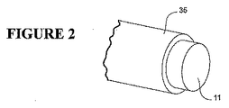
図示のリニアコンプレッサ1は、概していえば、主スプリングにより連結されたシリンダ部品と、ピストン部品とを有している。シリンダ部品は、シリンダシャーシ10と、シリンダヘッド11と、弁プレート5と、シリンダライナ12とを含んでいる。シリンダ部品はまた、リニア電気モータ用ステータ部品15を有している。シリンダヘッド11から遠位側のシリンダ部品の端部18には、シリンダ部品に対して主スプリングが取付けられている。図1に示す実施形態では、主スプリングは、コイルスプリング19と平スプリング20との組合せとして形成されている。図2に示す実施形態では、主スプリングは、平スプリング16の組合せからなる。
The illustrated linear compressor 1 generally has a cylinder part connected by a main spring and a piston part. The cylinder part includes a
ピストン部品は、側壁24およびクラウン14を備えた中空ピストン22を有している。ロッドが、クラウン14とリニアモータ17の支持体30とを連結している。図1において、ロッドは、中空ピストン22のほぼ中心にフレキシブル部分28を有している。図4では、ロッド21は、その全長に沿ってフレキシブルである。
The piston part has a
リニアモータアーマチャ17は、シリンダライナ内でのピストンの往復運動軸線に対して横方向の1または2以上の磁極を形成すべく磁化された永久磁石材料(例えばフェライトまたはネオジム)からなる本体を有している。ピストン22から遠位側にあるアーマチャ支持体30の一端部32は、主スプリングに連結されている。
The
図1に示すように、アーマチャは、その一端を主スプリングにより支持し、かつ他端をピストンによってのみ支持することができる。或いは、アーマチャには、図4に示すように、中間平スプリング40のような付加横方向支持体を設けることもできる。
リニアコンプレッサ1は、シェル2内で、該シェルからコンプレッサを隔絶すべく、複数の懸架スプリング上に取付けられている。使用時に、リニアコンプレッサの大きい外側本体およびシリンダ部品は、シリンダ部品内のピストン部品の往復運動軸線に沿って振動する。好ましいコンプレッサでは、ピストン部品は、シリンダ部品に比べ、故意に非常に軽く維持され、これにより、シリンダ部品の振動は、ピストン部品とシリンダ部品との相対往復運動と比較して小さくなる。図示の形態では、リニアコンプレッサは、全体として周方向に配置された4つの懸架スプリング31の組に取付けられている。特許文献1には、他の懸架スプリング構造が示されている。各懸架スプリングの端部はエラストマー緩衝器上に嵌合され、各スプリングの一端にはリニアコンプレッサ1が連結されかつ各スプリングの他端にはコンプレッサシェル2が連結されている。
As shown in FIG. 1, the armature can be supported at one end by a main spring and at the other end only by a piston. Alternatively, the armature can be provided with an additional lateral support, such as an intermediate
The linear compressor 1 is mounted on a plurality of suspension springs in the shell 2 to isolate the compressor from the shell. In use, the large outer body and cylinder part of the linear compressor vibrate along the reciprocating axis of the piston part within the cylinder part. In a preferred compressor, the piston part is intentionally kept very light compared to the cylinder part, so that the vibration of the cylinder part is small compared to the relative reciprocation of the piston part and the cylinder part. In the illustrated form, the linear compressor is attached to a set of four
この特許文献1には、本発明の改善されたヘッド組立体が有効である形式のリニアコンプレッサが簡単に開示されている。しかしながら、本発明の有効性は、図示の形式および形態のリニアコンプレッサに限定されないことは明らかである。本発明の改善は、広く適用できるものである。 This Patent Document 1 simply discloses a linear compressor of the type in which the improved head assembly of the present invention is effective. However, it is clear that the effectiveness of the present invention is not limited to linear compressors of the form and form shown. The improvement of the present invention can be widely applied.
図1に示したリニアコンプレッサの関連部分が、図2および図3に更に示されている。
この実施形態では、ヘッドカバーは、シリンダ部品10の主シャーシコンポーネントに組込まれている。ヘッドカバーは、一体部品として組込まれること、例えばフレームが製造されるときにフレームの残部と一体に鋳造されることが好ましい。かくして、ヘッド11は、シリンダ本体35の一端を包囲するキャップであると考えられる。
The relevant parts of the linear compressor shown in FIG. 1 are further illustrated in FIGS.
In this embodiment, the head cover is incorporated into the main chassis component of the
シリンダシャーシ10内の所定位置に弁プレート5が固定され、シリンダシャーシ内のスペースのヘッド部分を、シリンダシャーシ内のスペースのシリンダ部分から分割している。弁プレート5は少なくとも1つの排出弁孔を有し、かつ好ましくは弁プレートの一方の側に固定された排出弁6を支持している。
The
シャーシ10のシリンダ部分35の内面は円筒状であるのが好ましく、また弁プレート5の外周部は円形で、円筒面内にぴったり嵌合するのが好ましい。
シリンダライナ12は、シリンダ部分35の内面内に締り嵌めされるサイズを有する円筒状外面を有している。これにより、シリンダライナ12およびシリンダシャーシ10のシリンダ部分35が同じまたはほぼ同じ温度にあるときは、シリンダライナ12がシリンダシャーシ10内の所定位置に配置され、両部品が、更に固定または緊締する必要なくしてきつく係合される。
The inner surface of the
The
弁プレート5の外周部は、シリンダライナ12の端部37と、シリンダシャーシ10との間に係合される。シリンダシャーシ10は環状肩部39を有し、該肩部39およびシリンダライナ12の端部37が、弁プレート5の外周部38の対向側面と直接係合する。別の構成として、弁プレート5の外周部の回りに複数の肩部を分散配置することができる。また、シリンダシャーシ10と弁プレート5との間に中間スペーサを設けることもできる。
The outer peripheral portion of the
弁プレート5の外周部38には、シリンダライナ12の端部を受入れるための環状リベート(rebate)40を設けることができる。
An
弁プレート5は、シリンダライナ12の開端部に固定されている。弁プレートは、永久的接着および一体シールを形成すべく、溶着または接着により固定できる。接着シールまたは溶着シールは、ガスケットまたは同様な圧縮性シールの必要性を無くすことができる。溶着は、溶接またはロウ付により行うことができる。一般的な溶接は高温で、シリンダの幾何学的形状を大きく変えてしまう虞れがある。しかしながら、摩擦溶接は可能性がある。或いは、半田付け、銀ロウ付またはロウ付等の低温方法を使用することもできる。例えば、半田またはロウの予成形リングを弁プレートとシリンダライナの端部との間に保持し、この組立体を例えばオーブン内で、充填材の融点より高い温度まで加熱できる。組立体をオーブンから取出して冷却すれば、充填材が凝固し、弁プレートがシリンダライナの端部に固定される。
The
或いは、適当なグルー、接着剤または半田を用いて接合を行うこともできる。適当な接着剤として、エポキシグルー(例えばAraldite XP3131)、またはシアノアクリレート(スーパーグルー)等の熱硬化性グルーがある。グルーを用いた接着は、当該グルーに適した方法に従って行うべきである。 Alternatively, bonding can be performed using an appropriate glue, adhesive, or solder. Suitable adhesives include epoxy glue (eg Araldite XP3131) or thermosetting glue such as cyanoacrylate (super glue). Adhesion using glue should be performed according to a method suitable for the glue.
同じ改善、弁プレートのシリンダライナの端部への接合または溶着は、図4に示す他のコンプレッサの実施形態にも適用できる。この実施形態では、コンプレッサは、別のヘッドカバーを有している。弁プレート5の外周部はシリンダライナ12の外縁部を越えて延び、シリンダシャーシ10の端部にオーバーラップしている。この実施形態では、弁プレートは、ヘッドカバーを弁プレートの他側およびシリンダ組立体に固定する止めねじ、または同様なファスナを通す孔を有している。
The same improvement, the joining or welding of the valve plate to the end of the cylinder liner can also be applied to the other compressor embodiments shown in FIG. In this embodiment, the compressor has a separate head cover. The outer periphery of the
図1によるコンプレッサの好ましい組立方法には、弁プレートをシリンダライナに接合または溶着することが含まれる。次に、シリンダシャーシ(シリンダシャーシは、一般に鋳造アルミニウム合金である)が加熱される。シリンダライナ組立体は、弁プレート5用の円筒状キャビティ内に導入され、肩部39に対して突き合わせられる。シリンダライナ組立体は、シリンダが該組立体上に収縮するまでこの状態に保持される。リーズナブルな製造公差によればこの一貫性が達成され、シリンダライナ12とシリンダシャーシとの間の非常に有効な最終的係合は、シリンダシャーシを約250℃に加熱しかつライナを室温に放置することにより達成される。
A preferred method of assembling the compressor according to FIG. 1 includes joining or welding the valve plate to the cylinder liner. Next, the cylinder chassis (the cylinder chassis is typically a cast aluminum alloy) is heated. The cylinder liner assembly is introduced into the cylindrical cavity for the
溶着またはグルーイング(接着)により弁プレートをシリンダライナに固定することにより、両者の間に寸法的に安定したシールを形成できる。従来技術の一般的なガスケットシールは、組立中に圧縮される。ガスケットの孔を、引っ込むことなくシリンダ壁に完全に同一面にする充分な精度でサイズを定めかつ配置するのは困難である。過大サイズの孔では、圧縮スペース(ピストンがその最大ストロークの上死点にあるスペース)の体積は好ましいスペースより大きくなってしまう。過小サイズの孔では、ガスケットはシリンダ壁を越えて突出するため、ピストンは、突出するあらゆる可能性を回避するのに充分なクリアランスが得られるサイズにしなければならない。本発明によるシールは、これらの欠点を回避できる。 By fixing the valve plate to the cylinder liner by welding or gluing (adhesion), a dimensionally stable seal can be formed between them. Conventional gasket seals in the prior art are compressed during assembly. It is difficult to size and position the gasket holes with sufficient accuracy to make the holes of the gasket completely flush with the cylinder wall without being retracted. In an oversized hole, the volume of the compression space (the space where the piston is at the top dead center of its maximum stroke) will be larger than the preferred space. With undersized holes, the gasket protrudes beyond the cylinder wall, so the piston must be sized to provide sufficient clearance to avoid any possibility of protrusion. The seal according to the invention avoids these drawbacks.
本発明は、リニアコンプレッサ用シリンダ組立体を提供する。シリンダ組立体は、シリンダヘッドの端部から軸線に沿って延びているシリンダスペースを形成する内面をもつシリンダシャーシを有している。シリンダスペースは少なくとも実質的に円筒状である。両端が開放したシリンダライナがシャーシ内に配置される。ライナの外面は、シャーシの内面の一部を形成するシリンダスペースに係合される。弁プレートが、シリンダのシリンダヘッド端に接合または溶着される。弁プレートライナは、シリンダスペースのシリンダヘッド端をシーリング閉鎖する。弁プレートは、シリンダライナに溶接するのが好ましい。或いは、弁プレートは、シリンダライナにグルーイングされる。 The present invention provides a cylinder assembly for a linear compressor. The cylinder assembly has a cylinder chassis having an inner surface that forms a cylinder space extending along an axis from the end of the cylinder head. The cylinder space is at least substantially cylindrical. A cylinder liner open at both ends is placed in the chassis. The outer surface of the liner is engaged with a cylinder space that forms part of the inner surface of the chassis. A valve plate is joined or welded to the cylinder head end of the cylinder. The valve plate liner seals and closes the cylinder head end of the cylinder space. The valve plate is preferably welded to the cylinder liner. Alternatively, the valve plate is glued to the cylinder liner.
ライナの端面は、弁プレートの面に突き合わせるのが好ましい。
シリンダシャーシの内面はまたシリンダヘッドのスペースを形成するのが好ましく、弁プレートの外縁部はシリンダライナの外面と同一面であるか外面より内側に位置する。
The end face of the liner preferably abuts the face of the valve plate.
The inner surface of the cylinder chassis preferably also forms a space for the cylinder head, and the outer edge of the valve plate is flush with or inside the outer surface of the cylinder liner.
別の構成では、リニアコンプレッサはシリンダシャーシに固定されたヘッドを有し、弁プレートはシリンダライナの縁部を越えて延びている。
シリンダシャーシはシリンダライナの他端部を越えて延びるのが好ましく、例えばリニアモータのステータ部品を支持することができる。或いは、シリンダシャーシはシリンダライナの両端部の中間に終端して、シリンダライナの外面の一部のみをカバーするように構成できる。この場合には、別のシリンダ部品のフレームが、例えば締り摩擦嵌めにより、シリンダライナの他端部上に固定される。シリンダ部品のフレームは、リニアモータのステータ部品を支持する。
In another configuration, the linear compressor has a head secured to the cylinder chassis and the valve plate extends beyond the edge of the cylinder liner.
The cylinder chassis preferably extends beyond the other end of the cylinder liner and can support, for example, a linear motor stator component. Alternatively, the cylinder chassis can be configured to terminate in the middle of both ends of the cylinder liner and cover only a part of the outer surface of the cylinder liner. In this case, the frame of another cylinder part is fixed on the other end of the cylinder liner, for example by a tight friction fit. The frame of the cylinder part supports the stator part of the linear motor.
シリンダライナは、シャーシ内に締り嵌めされ、摩擦により所定位置に保持されるのが好ましい。
シャーシは、好ましくは、内面の部品を形成するシリンダと内面の部品を形成するヘッドとの間の遷移部に肩部(単一または複数)を有し、弁プレートは、一方の側が肩部(単一または複数)に、他方の側がシリンダライナの環状端部に押付けられている。
The cylinder liner is preferably an interference fit within the chassis and is held in place by friction.
The chassis preferably has a shoulder or shoulders at the transition between the cylinder forming the inner part and the head forming the inner part, and the valve plate is shouldered on one side ( Single or multiple), the other side is pressed against the annular end of the cylinder liner.
弁プレートには、1または2以上の弁部材を組付けることができる。
シリンダシャーシの内面またはシリンダライナの外面の1または2以上の溝は、圧縮ガスを、シリンダライナに形成されたガスベアリングポートに供給する供給通路を形成している。例えば本件出願人の所有する上記特許文献2に開示されているように、これらの溝は、シリンダライナの外面に設けるのが好ましい。この場合には、圧縮ガス放出スペースと、シャーシとライナとの間に形成されたガスベアリング供給通路との間に流路を形成すべく、弁プレートの外周部に1または2以上のノッチを設けるのが好ましい。
One or more valve members can be assembled to the valve plate.
One or more grooves in the inner surface of the cylinder chassis or the outer surface of the cylinder liner form a supply passage for supplying compressed gas to a gas bearing port formed in the cylinder liner. For example, as disclosed in Patent Document 2 owned by the present applicant, these grooves are preferably provided on the outer surface of the cylinder liner. In this case, one or more notches are provided in the outer peripheral portion of the valve plate to form a flow path between the compressed gas discharge space and the gas bearing supply passage formed between the chassis and the liner. Is preferred.
シリンダ組立体は、特に、気密ハウジングおよび該気密ハウジング内のリニアコンプレッサを備えた冷凍システムのコンプレッサに設けられる。コンプレッサは、シリンダ部品組立体と、シリンダライナにより形成されたシリンダ内を往復運動するピストンを備えたピストン部品と、ピストンとシリンダ部品との間で往復駆動するリニア電気モータとを有している。リニアコンプレッサは、気密ハウジング内で作動するように懸架されている。 The cylinder assembly is provided in particular in a compressor of a refrigeration system comprising a hermetic housing and a linear compressor in the hermetic housing. The compressor includes a cylinder component assembly, a piston component including a piston that reciprocates within a cylinder formed by a cylinder liner, and a linear electric motor that reciprocates between the piston and the cylinder component. The linear compressor is suspended to operate within the hermetic housing.
シリンダ組立体は、リニアコンプレッサの改善された製造方法、特に、リニアコンプレッサのシリンダ部分の組立方法を考慮に入れたものである。
本発明の方法は、弁プレートをシリンダライナまたはシリンダライナ組立体に溶着または接合することから開始する。次に、示差温度により、シリンダシャーシがシリンダライナ組立体に対して拡大される。シリンダライナ組立体が、開端部を通して拡大シリンダシャーシ内に挿入され、シリンダシャーシに対して弁プレートを係合させる。
The cylinder assembly takes into account the improved manufacturing method of the linear compressor, in particular the assembly method of the cylinder part of the linear compressor.
The method of the present invention begins with welding or joining a valve plate to a cylinder liner or cylinder liner assembly. Next, the differential temperature causes the cylinder chassis to expand relative to the cylinder liner assembly. A cylinder liner assembly is inserted through the open end into the enlarged cylinder chassis to engage the valve plate against the cylinder chassis.
シリンダライナ組立体は、示差温度が低下し、シリンダシャーシおよびシリンダライナ組立体が係合されるまでこの位置に保持される。 The cylinder liner assembly is held in this position until the differential temperature decreases and the cylinder chassis and cylinder liner assembly are engaged.
1 リニアコンプレッサ
2 ハウジング(シェル)
5 出口弁プレート
10 シリンダシャーシ
11 シリンダヘッド
12 シリンダライナ
16、20 平スプリング
19 コイルスプリング
22 ピストン
31 懸架スプリング
1 Linear compressor 2 Housing (shell)
5
Claims (16)
シリンダヘッドの端部から一軸線に沿って延びるシリンダスペースを形成する内面を備えたシリンダシャーシであって、前記シリンダスペースが少なくとも実質的に円筒状であるシリンダシャーシと、
両端部が開放した円筒状のシリンダライナであって、外面が前記シャーシの一部を形成するシリンダスペースに係合するようにして前記シャーシ内に配置されているシリンダライナと、
前記シリンダスペースのヘッド端をシーリング閉鎖すべく、前記シリンダライナのシリンダヘッドの端部に接合または溶着されている弁プレートとを備えている、
ことを特徴とするリニアコンプレッサ用シリンダ組立体。 A cylinder assembly for a linear compressor,
A cylinder chassis having an inner surface forming a cylinder space extending along one axis from an end of the cylinder head, wherein the cylinder space is at least substantially cylindrical;
A cylindrical cylinder liner open at both ends, a cylinder liner disposed in the chassis such that an outer surface engages a cylinder space forming a part of the chassis;
A valve plate joined or welded to the end of the cylinder head of the cylinder liner for sealing and closing the head end of the cylinder space.
A cylinder assembly for a linear compressor.
請求項1記載のシリンダ組立体。 The valve plate is welded to the cylinder liner;
The cylinder assembly according to claim 1.
請求項1記載のシリンダ組立体。 The valve plate is bonded to the cylinder liner;
The cylinder assembly according to claim 1.
請求項1から3のいずれか1項に記載のシリンダ組立体。 An end surface of the liner is in contact with a surface of the valve plate;
The cylinder assembly according to any one of claims 1 to 3.
前記弁プレートの外縁部は、前記シリンダライナの外面と同一面内にあるか、これより内側にある、
請求項1から4のいずれか1項に記載のシリンダ組立体。 The inner surface of the cylinder chassis forms a cylinder head space;
An outer edge portion of the valve plate is in the same plane as the outer surface of the cylinder liner or on the inner side thereof;
The cylinder assembly according to any one of claims 1 to 4.
前記弁プレートは、一方の側が肩部(単一または複数)に、かつ他方の側がシリンダライナに押付けられている、
請求項5記載のシリンダ組立体。 The chassis has a shoulder (single or plural) at the transition between the cylinder forming part of the inner surface and the head forming part of the inner surface,
The valve plate has one side pressed against the shoulder (single or multiple) and the other side pressed against the cylinder liner,
The cylinder assembly according to claim 5.
前記弁プレートはシリンダライナの縁部を越えて延びている、
請求項1から4のいずれか1項に記載のシリンダ組立体。 The linear compressor has a head fixed to a cylinder chassis,
The valve plate extends beyond the edge of the cylinder liner;
The cylinder assembly according to any one of claims 1 to 4.
請求項1から7のいずれか1項に記載のシリンダ組立体。 The cylinder chassis extends beyond the other end of the cylinder liner and supports the stator parts of the linear motor;
The cylinder assembly according to any one of claims 1 to 7.
請求項1から7のいずれか1項に記載のシリンダ組立体。 The cylinder chassis terminates in the middle of both ends of the cylinder liner and covers only a part of the outer surface of the cylinder liner.
The cylinder assembly according to any one of claims 1 to 7.
請求項9記載のシリンダ組立体。 Another cylinder part frame is fixed on the other end of the cylinder liner, and the frame supports the stator part of the linear motor.
The cylinder assembly according to claim 9.
請求項1から10のいずれか1項記載のシリンダ組立体。 The cylinder liner is an interference fit within the chassis and held in place by friction;
The cylinder assembly according to any one of claims 1 to 10.
請求項1から11のいずれか1項記載のシリンダ組立体。 The valve plate is assembled with one or more valve members.
The cylinder assembly according to any one of claims 1 to 11.
請求項1から12のいずれか1項に記載のシリンダ組立体。 One or more grooves on the inner surface of the cylinder chassis or the outer surface of the cylinder liner form a supply passage for supplying compressed gas to a gas bearing port formed in the cylinder liner.
The cylinder assembly according to any one of claims 1 to 12.
請求項13記載のシリンダ組立体。 The groove is provided on the outer surface of the cylinder liner, and one or more notches on the outer periphery of the valve plate are formed between the compressed gas discharge space of the head and the gas bearing supply passage formed between the chassis and the liner. Forming a flow path in the
The cylinder assembly according to claim 13.
ことを特徴とする冷凍システムのコンプレッサ。 An airtight housing and a linear compressor in the airtight housing, wherein the compressor is reciprocated in a cylinder formed by the cylinder part assembly according to any one of claims 1 to 13 and the cylinder liner. A linear electric motor that drives a reciprocating motion between the piston part and the cylinder part, and the linear compressor is suspended so as to be able to rotate in the hermetic housing.
A compressor for a refrigeration system.
シリンダライナ組立体に対してシリンダシャーシを示差温度により拡大させることにより、弁プレートをシリンダライナに溶着または接合してリンダライナ組立体とする段階と、
該シリンダライナ組立体を、開端部を通して挿入し。弁プレートをシリンダシャーシに係合させる段階と、
示差温度が低下して、シリンダシャーシおよびシリンダライナ組立体が係合されるまで、シリンダライナ組立体をこの位置に保持する段階とを有する、
ことを特徴とするリニアコンプレッサの製造方法。 In a method for manufacturing a linear compressor, including assembling a cylinder portion of the linear compressor,
Expanding the cylinder chassis relative to the cylinder liner assembly with a differential temperature to weld or join the valve plate to the cylinder liner to form a liner liner assembly;
Insert the cylinder liner assembly through the open end. Engaging the valve plate with the cylinder chassis;
Holding the cylinder liner assembly in this position until the differential temperature is reduced and the cylinder chassis and cylinder liner assembly are engaged.
A manufacturing method of a linear compressor characterized by the above.
Applications Claiming Priority (2)
| Application Number | Priority Date | Filing Date | Title |
|---|---|---|---|
| NZ54140705 | 2005-07-21 | ||
| PCT/NZ2006/000183 WO2007011246A2 (en) | 2005-07-21 | 2006-07-21 | Linear compressor cylinder and head construction |
Publications (1)
| Publication Number | Publication Date |
|---|---|
| JP2009501874A true JP2009501874A (en) | 2009-01-22 |
Family
ID=37669254
Family Applications (1)
| Application Number | Title | Priority Date | Filing Date |
|---|---|---|---|
| JP2008522726A Pending JP2009501874A (en) | 2005-07-21 | 2006-07-21 | Linear compressor cylinder and head structure |
Country Status (8)
| Country | Link |
|---|---|
| US (1) | US20080219868A1 (en) |
| JP (1) | JP2009501874A (en) |
| KR (1) | KR20080024229A (en) |
| CN (1) | CN100559027C (en) |
| AU (1) | AU2006270593B2 (en) |
| BR (1) | BRPI0613689A2 (en) |
| DE (1) | DE112006001911T5 (en) |
| WO (1) | WO2007011246A2 (en) |
Families Citing this family (9)
| Publication number | Priority date | Publication date | Assignee | Title |
|---|---|---|---|---|
| NZ526361A (en) * | 2003-05-30 | 2006-02-24 | Fisher & Paykel Appliances Ltd | Compressor improvements |
| WO2006049513A2 (en) * | 2004-11-02 | 2006-05-11 | Fisher & Paykel Appliances Limited | Linear compressor cylinder and head construction |
| BRPI0705541A2 (en) * | 2007-12-18 | 2009-08-18 | Whirlpool Sa | arrangement and assembly process of resonant spring in refrigeration compressor |
| AT10394U1 (en) * | 2008-03-19 | 2009-02-15 | Acc Austria Gmbh | REFRIGERANT COMPRESSOR |
| CN104454468B (en) * | 2014-12-12 | 2016-11-09 | 常熟市淼泉压缩机配件有限公司 | Seal cylinder cap |
| US10001120B2 (en) * | 2015-08-31 | 2018-06-19 | Bendix Commercial Vehicle Systems Llc | Lightweight compressor crankcase assembly and method |
| CN106246504B (en) * | 2016-09-12 | 2018-09-28 | 珠海格力电器股份有限公司 | Linear compressor |
| US20210164463A1 (en) * | 2017-10-19 | 2021-06-03 | Active Tools International (Hk) Ltd. | Air compressor cylinder, air compressor, vehicle seat, and vehicle |
| CN107962432B (en) * | 2018-01-09 | 2023-09-26 | 河南理工大学 | Clamping main shaft system for electrolytic grinding of thin disc workpieces |
Citations (3)
| Publication number | Priority date | Publication date | Assignee | Title |
|---|---|---|---|---|
| JPH1054360A (en) * | 1996-05-08 | 1998-02-24 | Lg Electron Inc | Linear compressor |
| JP2003512581A (en) * | 1999-10-21 | 2003-04-02 | フィッシャー アンド ペイケル アプライアンシズ リミティド | Linear compressor |
| JP2006528309A (en) * | 2003-05-30 | 2006-12-14 | フィッシャー アンド ペイケル アプライアンシーズ リミテッド | Improved compressor |
Family Cites Families (10)
| Publication number | Priority date | Publication date | Assignee | Title |
|---|---|---|---|---|
| US4538964A (en) * | 1984-01-04 | 1985-09-03 | Mechanical Technology Incorporated | Multistage resonant compressor |
| JPH04121477U (en) * | 1991-04-16 | 1992-10-29 | サンデン株式会社 | Free piston type compressor |
| US5332422A (en) * | 1993-07-06 | 1994-07-26 | Ford Motor Company | Solid lubricant and hardenable steel coating system |
| US6848892B1 (en) * | 1997-10-15 | 2005-02-01 | Matsushita Refrigeration Company | Oscillation-type compressor |
| JP2950809B1 (en) * | 1998-05-07 | 1999-09-20 | エルジー電子株式会社 | Oil supply device for linear compressor |
| TW504546B (en) * | 2000-10-17 | 2002-10-01 | Fisher & Amp Paykel Ltd | A linear compressor |
| NZ515578A (en) * | 2001-11-20 | 2004-03-26 | Fisher & Paykel Appliances Ltd | Reduction of power to free piston linear motor to reduce piston overshoot |
| BR0203724B1 (en) * | 2002-09-12 | 2011-08-09 | fluid pump and fluid transfer plate and inductive sensor for fluid pump. | |
| US7390177B2 (en) * | 2003-05-22 | 2008-06-24 | Danfoss Compressors Gmbh | Piston compressor, particularly a hermetic refrigerant compressor |
| KR100565485B1 (en) * | 2003-06-04 | 2006-03-30 | 엘지전자 주식회사 | Linear compressor |
-
2006
- 2006-07-21 AU AU2006270593A patent/AU2006270593B2/en not_active Ceased
- 2006-07-21 CN CNB2006800266386A patent/CN100559027C/en not_active Expired - Fee Related
- 2006-07-21 WO PCT/NZ2006/000183 patent/WO2007011246A2/en active Application Filing
- 2006-07-21 DE DE112006001911T patent/DE112006001911T5/en not_active Ceased
- 2006-07-21 US US11/996,022 patent/US20080219868A1/en not_active Abandoned
- 2006-07-21 BR BRPI0613689-3A patent/BRPI0613689A2/en not_active Application Discontinuation
- 2006-07-21 KR KR1020087002634A patent/KR20080024229A/en not_active Application Discontinuation
- 2006-07-21 JP JP2008522726A patent/JP2009501874A/en active Pending
Patent Citations (3)
| Publication number | Priority date | Publication date | Assignee | Title |
|---|---|---|---|---|
| JPH1054360A (en) * | 1996-05-08 | 1998-02-24 | Lg Electron Inc | Linear compressor |
| JP2003512581A (en) * | 1999-10-21 | 2003-04-02 | フィッシャー アンド ペイケル アプライアンシズ リミティド | Linear compressor |
| JP2006528309A (en) * | 2003-05-30 | 2006-12-14 | フィッシャー アンド ペイケル アプライアンシーズ リミテッド | Improved compressor |
Also Published As
| Publication number | Publication date |
|---|---|
| AU2006270593B2 (en) | 2011-03-10 |
| AU2006270593A1 (en) | 2007-01-25 |
| CN101248272A (en) | 2008-08-20 |
| KR20080024229A (en) | 2008-03-17 |
| CN100559027C (en) | 2009-11-11 |
| WO2007011246A2 (en) | 2007-01-25 |
| US20080219868A1 (en) | 2008-09-11 |
| WO2007011246A3 (en) | 2007-04-05 |
| BRPI0613689A2 (en) | 2011-01-25 |
| DE112006001911T5 (en) | 2008-06-05 |
Similar Documents
| Publication | Publication Date | Title |
|---|---|---|
| JP2009501874A (en) | Linear compressor cylinder and head structure | |
| JP2006132527A (en) | Linear compressor | |
| JP4064827B2 (en) | Reciprocating compressor | |
| US20080075610A1 (en) | Linear Compressor Cylinder and Head Construction | |
| JP2009501873A (en) | Linear compressor | |
| JP2000320463A (en) | Small pump | |
| JP2005532500A (en) | Resonator for linear compressor | |
| KR100906729B1 (en) | Linear electric motor and compressor having the same | |
| JP2003166468A (en) | Reciprocating compressor | |
| KR20040023096A (en) | Union structure for stator in reciprocating compressor | |
| JP2005201114A (en) | Compressor | |
| CN108518332B (en) | Linear compressor | |
| JP4109250B2 (en) | Stator fixing device for reciprocating compressor | |
| KR100301477B1 (en) | Structure for supporting spring | |
| WO2006049512A2 (en) | Piston rod connection forlinear compressor | |
| US20070020121A1 (en) | Suspension Element for Linear Compressor | |
| JP2006029137A (en) | Vibrational compressor | |
| KR20040021453A (en) | Reciprocating compressor | |
| JP3752573B2 (en) | Drive spring connecting structure in refrigerator | |
| JP2006077701A (en) | Hermetic-type compressor | |
| JP2557773Y2 (en) | Vibration compressor | |
| KR100218481B1 (en) | Motor laminating fixing and spring supporter of a linear compressor | |
| JP2004092618A (en) | Compressor | |
| JP2006029223A (en) | Vibration compressor | |
| JP2785781B2 (en) | Stirling refrigerator and method of manufacturing the same |
Legal Events
| Date | Code | Title | Description |
|---|---|---|---|
| A131 | Notification of reasons for refusal |
Free format text: JAPANESE INTERMEDIATE CODE: A131 Effective date: 20101012 |
|
| A02 | Decision of refusal |
Free format text: JAPANESE INTERMEDIATE CODE: A02 Effective date: 20110427 |