JP2009292000A - Method of producing pneumatic tire and apparatus therefor - Google Patents

Method of producing pneumatic tire and apparatus therefor Download PDF

Info

Publication number
JP2009292000A
JP2009292000A JP2008146529A JP2008146529A JP2009292000A JP 2009292000 A JP2009292000 A JP 2009292000A JP 2008146529 A JP2008146529 A JP 2008146529A JP 2008146529 A JP2008146529 A JP 2008146529A JP 2009292000 A JP2009292000 A JP 2009292000A
Authority
JP
Japan
Prior art keywords
steel cord
cord
amplitude
corrugated steel
tire
Prior art date
Legal status (The legal status is an assumption and is not a legal conclusion. Google has not performed a legal analysis and makes no representation as to the accuracy of the status listed.)
Pending
Application number
JP2008146529A
Other languages
Japanese (ja)
Inventor
Yuichiro Ogawa
裕一郎 小川
Current Assignee (The listed assignees may be inaccurate. Google has not performed a legal analysis and makes no representation or warranty as to the accuracy of the list.)
Bridgestone Corp
Original Assignee
Bridgestone Corp
Priority date (The priority date is an assumption and is not a legal conclusion. Google has not performed a legal analysis and makes no representation as to the accuracy of the date listed.)
Filing date
Publication date
Application filed by Bridgestone Corp filed Critical Bridgestone Corp
Priority to JP2008146529A priority Critical patent/JP2009292000A/en
Publication of JP2009292000A publication Critical patent/JP2009292000A/en
Pending legal-status Critical Current

Links

Images

Classifications

    • DTEXTILES; PAPER
    • D07ROPES; CABLES OTHER THAN ELECTRIC
    • D07BROPES OR CABLES IN GENERAL
    • D07B7/00Details of, or auxiliary devices incorporated in, rope- or cable-making machines; Auxiliary apparatus associated with such machines
    • D07B7/02Machine details; Auxiliary devices
    • D07B7/025Preforming the wires or strands prior to closing

Abstract

<P>PROBLEM TO BE SOLVED: To uniformize amplitude (a) of a corrugated steel cord 32 in the whole of a cord reinforced layer 30, and to efficiently form the cord reinforced layer 30 while facilitating control. <P>SOLUTION: The cord reinforced layer 30 is molded by winding the corrugated steel cord 32 with the amplitude (a) gradually increasing, around a cylindrical molding drum 35 for several times as it is, and the amplitude (a) of the corrugated steel cord 32 in the cord reinforced layer 30 is increased as it separates axially from a set point P of a bead core 12. Thus, when an unvulcanized tire including the cord reinforced layer 30 is deformed approximately toroidally, the decrease and increase of the amplitude of the corrugated steel cord 32 cancel with each other to uniformize the amplitude (a) and facilitates control in winding to increase the work efficiency. <P>COPYRIGHT: (C)2010,JPO&INPIT

Description

この発明は、ビード部からショルダー部までの間に波状スチールコードのコード補強層を配置した空気入りタイヤの製造方法および装置に関する。     The present invention relates to a method and an apparatus for manufacturing a pneumatic tire in which a cord reinforcing layer of a corrugated steel cord is disposed between a bead portion and a shoulder portion.

従来の空気入りタイヤとしては、カーカス層の折返し端におけるセパレーション等を抑制することでビード耐久性を向上させるため、例えば、特許文献1に記載のように、ビード部からショルダー部までの間に部分的に、ここではカーカス層の折返し部に重なり合ったコード補強層(ワイヤーチェーファー)を配置したものが知られている。     As a conventional pneumatic tire, in order to improve bead durability by suppressing separation at the folded end of the carcass layer, for example, as described in Patent Document 1, a portion between the bead portion and the shoulder portion is used. Specifically, here, there is known a structure in which a cord reinforcing layer (wire chafer) is disposed so as to overlap the folded portion of the carcass layer.

そして、このようなコード補強層は略トロイダル状をしたカーカス層の折返し部の軸方向外側に直接、ゴム被覆された単線スチールコードをほぼ同一振幅、同一波長の波状に屈曲させながら渦巻き状に巻き付けることで成形するようにしているが、このようにしてコード補強層を成形する場合には、スチールコードを複雑に湾曲した曲線に沿って誘導しなければならないため、巻き付けの際の制御が複雑になるとともに、作業能率も低下してしまうという課題があった。   Such a cord reinforcing layer is wound in a spiral shape while bending a rubber-coated single wire steel cord into a wave shape having substantially the same amplitude and the same wavelength directly outside the folded portion of the carcass layer having a substantially toroidal shape. However, when forming the cord reinforcement layer in this way, the steel cord must be guided along a complicated curved curve, so the control during winding is complicated. At the same time, there is a problem that the work efficiency is lowered.

このような課題を解決するため、例えば、特許文献2に記載のような円筒状の成形ドラムに、実質上同一振幅、同一波長である波状に屈曲した波状スチールコードを複数回螺旋状に巻き付けて円筒状のコード補強層を成形するとともに、カーカスプライ等を該成形ドラムに巻き付けて円筒状のカーカス層を成形する一方、該カーカス層の軸方向両端部外側のセット位置にビードコアをそれぞれセットして円筒状のタイヤ中間体を成形することが考えられる。   In order to solve such a problem, for example, a wavy steel cord bent into a wavy shape having substantially the same amplitude and the same wavelength is wound around a cylindrical forming drum as described in Patent Document 2 a plurality of times. A cylindrical cord reinforcing layer is formed, and a carcass ply or the like is wound around the forming drum to form a cylindrical carcass layer. On the other hand, bead cores are respectively set at set positions outside both axial ends of the carcass layer. It is conceivable to form a cylindrical tire intermediate.

特開2006−160053号公報JP 2006-160053 A 特開平11−309789号公報Japanese Patent Laid-Open No. 11-309789

しかしながら、このようにして成形されたタイヤ中間体を、その後、略トロイダル状に膨出変形させるとともに、該タイヤ中間体の外側にベルト層、トレッドを貼付けて未加硫タイヤとした後、該未加硫タイヤを加硫して空気入りタイヤとすると、略トロイダル状に変形するときに前記コード補強層がビードコアから離隔するに従い(半径方向外側の部位ほど)周方向に大きく引き伸ばされるため、コード補強層を構成する波状スチールコードはビードコアから離隔したものほど振幅が小さくなる一方、波長が長くなる。この結果、波状スチールコードの振幅、波長がコード補強層全体で、特に半径方向に見たとき、かなり不均一となり、前述したビード耐久性の向上を充分に図ることができなくなるという課題があった。     However, after the tire intermediate body thus formed is bulged and deformed in a substantially toroidal shape, and a belt layer and a tread are pasted on the outer side of the tire intermediate body to form an unvulcanized tire, When a vulcanized tire is vulcanized to form a pneumatic tire, the cord reinforcement layer is greatly stretched in the circumferential direction as the cord reinforcement layer is separated from the bead core when deformed into a substantially toroidal shape. As the wavy steel cords constituting the layers are separated from the bead core, the amplitude becomes smaller, while the wavelength becomes longer. As a result, the amplitude and wavelength of the corrugated steel cord are considerably uneven when viewed from the entire cord reinforcement layer, particularly in the radial direction, and it is impossible to sufficiently improve the above-described bead durability. .

この発明は、制御が容易でありながら高能率でコード補強層を成形することができるとともに、波状スチールコードの振幅をコード補強層全体で均一化することができる空気入りタイヤの製造方法および装置を提供することを目的とする。   The present invention provides a pneumatic tire manufacturing method and apparatus capable of forming a cord reinforcement layer with high efficiency while being easy to control, and capable of making the amplitude of the corrugated steel cord uniform throughout the cord reinforcement layer. The purpose is to provide.

このような目的は、第1に、両端部にビードコアがセットされたトロイダル状に延びるカーカス層と、ビード部からショルダー部までの間に部分的に配置され、周方向に延びるとともに波状に屈曲した波状スチールコードを有するコード補強層と、カーカス層の半径方向外側に少なくとも配置されたトレッドとを有する空気入りタイヤの製造方法であって、直線状に延びるスチールコードを波状に屈曲させて振幅が長手方向に徐々に変化する波状スチールコードを成形する工程と、円筒状の成形ドラムにカーカスプライを巻き付けて円筒状のカーカス層を成形するとともに、該カーカス層の軸方向両端部外側のセット位置にビードコアをそれぞれセットする一方、前記波状スチールコードを前記成形ドラムにそのまま複数回巻き付けて、ビードコアのセット位置から軸方向に離隔するに従い該波状スチールコードの振幅が大となったコード補強層を成形し、円筒状のタイヤ中間体を成形する工程と、前記タイヤ中間体を略トロイダル状に膨出変形させるとともに、該タイヤ中間体の外側に少なくともトレッドを貼付けて未加硫タイヤを成形する工程と、前記未加硫タイヤを加硫して空気入りタイヤとする工程とを備えた空気入りタイヤの製造方法により、達成することができる。     The purpose of this is as follows. First, a carcass layer extending in a toroidal shape with bead cores set at both ends and a portion between the bead portion and the shoulder portion, and extending in the circumferential direction and bent in a wave shape. A method of manufacturing a pneumatic tire having a cord reinforcing layer having a corrugated steel cord and a tread disposed at least radially outward of the carcass layer, wherein a linearly corded steel cord is bent into a corrugated shape and the amplitude is long. Forming a corrugated steel cord that gradually changes in the direction, winding a carcass ply around a cylindrical forming drum to form a cylindrical carcass layer, and forming a bead core at a set position outside both axial ends of the carcass layer Each of which is wound around the forming drum several times as it is, A step of forming a cord reinforcing layer in which the amplitude of the corrugated steel cord is increased as the distance from the set position of the core in the axial direction is increased, and a cylindrical tire intermediate is formed; and the tire intermediate is substantially toroidal. Pneumatic including a step of bulging and deforming, and a step of forming an unvulcanized tire by pasting at least a tread on the outer side of the tire intermediate, and a step of vulcanizing the unvulcanized tire to form a pneumatic tire This can be achieved by the tire manufacturing method.

第2に、両端部にビードコアがセットされたトロイダル状に延びるカーカス層と、ビード部からショルダー部までの間に部分的に配置され、周方向に延びるとともに波状に屈曲した波状スチールコードを有するコード補強層と、カーカス層の半径方向外側に少なくとも配置されたトレッドとを有する空気入りタイヤの製造装置であって、直線状に延びるスチールコードを波状に屈曲させて振幅が長手方向に徐々に変化する波状スチールコードを成形する屈曲手段と、円筒状の成形ドラムの外側にカーカスプライを供給して巻き付け円筒状のカーカス層を成形するカーカス供給手段と、前記カーカス層の軸方向両端部外側のセット位置にビードコアを供給してそれぞれセットするビードコア供給手段と、前記波状スチールコードを前記成形ドラムにそのまま供給して複数回巻き付けることで、成形ドラム上に該波状スチールコードの振幅がビードコアのセット位置から軸方向に離隔するに従い大となったコード補強層を成形するコード供給手段と、前記カーカス層、ビードコア、コード補強層を有する円筒状のタイヤ中間体を略トロイダル状に膨出変形させるとともに、該タイヤ中間体の半径方向外側に少なくともトレッドを貼付けて未加硫タイヤを成形する成形手段と、前記未加硫タイヤを加硫して空気入りタイヤとする加硫手段とを備えた空気入りタイヤの製造装置により、達成することができる。   Secondly, a cord having a toroidal carcass layer with bead cores set at both ends and a corrugated steel cord partially disposed between the bead portion and the shoulder portion and extending in the circumferential direction and bent in a wave shape An apparatus for manufacturing a pneumatic tire having a reinforcing layer and a tread disposed at least radially outside the carcass layer, wherein a linearly extending steel cord is bent into a wave shape, and the amplitude gradually changes in the longitudinal direction. Bending means for forming a corrugated steel cord; carcass ply for supplying a carcass ply to the outside of a cylindrical forming drum to form a cylindrical carcass layer; and set positions on both outer sides in the axial direction of the carcass layer A bead core supplying means for supplying and setting the bead core to each other, and the corrugated steel cords A cord supplying means for forming a cord reinforcing layer that is increased as the amplitude of the corrugated steel cord is increased in the axial direction from the set position of the bead core on the forming drum by being wound as it is and wound several times. A cylindrical tire intermediate body having a layer, a bead core, and a cord reinforcing layer is bulged and deformed in a substantially toroidal shape, and at least a tread is attached to the radially outer side of the tire intermediate body to form an unvulcanized tire; This can be achieved by a pneumatic tire manufacturing apparatus provided with vulcanizing means for vulcanizing the unvulcanized tire to form a pneumatic tire.

前述のようにコード補強層を有する円筒状のタイヤ中間体を略トロイダル状に膨出変形させると、コード補強層がビードコアから離隔するに従い周方向に大きく引き伸ばされて、該コード補強層を構成する波状スチールコードの振幅がビードコアから離隔するに従い減少するが、請求項1に係る発明のように振幅が徐々に変化する波状スチールコードを円筒状の成形ドラムにそのまま複数回巻き付けることで、該波状スチールコードの振幅をビードコアのセット位置から軸方向に離隔するに従い増大させれば、前述した波状スチールコードの振幅減少と振幅増大とが相殺し合って空気入りタイヤにおける波状スチールコードの振幅がコード補強層全体で、特に半径方向に見て近似(均一化)し、タイヤ性能が向上する。   As described above, when the cylindrical tire intermediate body having the cord reinforcing layer is bulged and deformed in a substantially toroidal shape, the cord reinforcing layer is greatly stretched in the circumferential direction as it is separated from the bead core, thereby constituting the cord reinforcing layer. Although the amplitude of the corrugated steel cord decreases as the distance from the bead core increases, the corrugated steel cord having a gradually changing amplitude as in the invention according to claim 1 is wound around the cylindrical forming drum as it is a plurality of times, thereby being corrugated steel cord. If the amplitude of the cord is increased as the distance from the set position of the bead core increases in the axial direction, the above-described decrease in amplitude and increase in amplitude of the corrugated steel cord cancel each other, and the amplitude of the corrugated steel cord in the pneumatic tire becomes the cord reinforcement layer. Overall, the tire performance is improved by approximating (homogenizing) particularly in the radial direction.

また、直線状に延びるスチールコードを屈曲させるだけで徐々に振幅が変化する波状スチールコードを製造しているため、該スチールコードに対して過剰な変形を生じさせることはなく、この結果、耐久性の高いコード補強層を成形することができるとともに、予め屈曲させた波状スチールコードをそのまま巻き付けるようにしているため、巻付け直後における波状スチールコードの振幅を各部で高精度とすることができる。   Moreover, since the corrugated steel cord whose amplitude gradually changes by bending the steel cord extending in a straight line is not produced, it does not cause excessive deformation to the steel cord, resulting in durability. In addition to being able to form a high-strength cord reinforcing layer and winding the wavy steel cord bent in advance, the amplitude of the wavy steel cord immediately after winding can be made high in each part.

しかも、スチールコードは円筒状の成形ドラムに対する巻付けに先立ってその振幅が徐々に変化するよう波状に屈曲されているので、巻付けの際、波状スチールコードを成形ドラムの軸線に平行な直線に沿って綾振り誘導するだけで充分であり、この結果、巻付けの際の制御が簡単となるとともに、作業能率を向上させることもできる。そして、前述のような空気入りタイヤは請求項3に記載の装置により容易かつ高能率で成形することができる。   Moreover, since the steel cord is bent in a wave shape so that its amplitude gradually changes prior to winding around the cylindrical forming drum, when winding, the wavy steel cord is made a straight line parallel to the axis of the forming drum. It is sufficient to guide the traversing along, and as a result, the control during winding becomes simple and the work efficiency can be improved. The pneumatic tire as described above can be easily and efficiently formed by the apparatus according to claim 3.

また、請求項2に記載のように構成すれば、コード補強層を高能率で簡単かつ安価に成形することができ、さらに、請求項4に記載のように構成すれば、振幅が徐々に変化する波状スチールコードを容易かつ高精度で製作することができ、また、請求項5に記載のように構成すれば、簡単な構造でありながら波状スチールコードを容易かつ高精度で製作することができる。   Further, if configured as in claim 2, the cord reinforcing layer can be easily and inexpensively molded with high efficiency, and if configured as in claim 4, the amplitude gradually changes. The corrugated steel cord can be manufactured easily and with high accuracy, and if configured as described in claim 5, the corrugated steel cord can be manufactured easily and with high accuracy while having a simple structure. .

以下、この発明の実施形態1を図面に基づいて説明する。
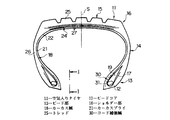
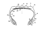
図1、2において、11は、例えばトラック・バス等に用いられる加硫済みの空気入りラジアルタイヤであり、この空気入りタイヤ11は対をなすビードコア12がそれぞれ埋設された一対のビード部13を有し、これらビード部13からは略半径方向外側に向かってサイドウォール部14がそれぞれ延びている。15は略円筒状を呈するトレッド部であり、このトレッド部15の軸方向両端と前記サイドウォール部14の半径方向外端との間には一対のショルダー部16が位置している。
Embodiment 1 of the present invention will be described below with reference to the drawings.
1 and 2, 11 is a vulcanized pneumatic radial tire used for trucks and buses, for example, and this pneumatic tire 11 has a pair of bead portions 13 each having a pair of bead cores 12 embedded therein. The side wall portions 14 extend from the bead portions 13 substantially outward in the radial direction. Reference numeral 15 denotes a tread portion having a substantially cylindrical shape, and a pair of shoulder portions 16 are located between both axial ends of the tread portion 15 and radially outer ends of the sidewall portions 14.

そして、この空気入りタイヤ11は前記ビードコア12間をトロイダル状に延びてサイドウォール部14、トレッド部15を補強するカーカス層18を有し、このカーカス層18はその両端部が前記ビードコア12および該ビードコア12に半径方向内端が係止されたフィラー19の回りに折り返されることで、両端部にビードコア12がセットされている。前記カーカス層18は内部にラジアル方向(子午線方向)に延びる多数本の非伸張性コード、ここではスチールコード20が埋設された少なくとも1枚(この実施形態では1枚)のカーカスプライ21から構成されている。   The pneumatic tire 11 has a carcass layer 18 that extends between the bead cores 12 in a toroidal manner and reinforces the sidewall portions 14 and the tread portions 15. The carcass layer 18 has both end portions of the bead core 12 and the The bead cores 12 are set at both ends by folding back around the filler 19 whose inner end in the radial direction is locked to the bead core 12. The carcass layer 18 is composed of at least one (in this embodiment, one) carcass ply 21 in which a plurality of non-stretchable cords extending in the radial direction (the meridian direction), in this case, steel cords 20 are embedded. ing.

ここで、前記ビードコア12間に位置するカーカス層18の内側にはゴムからなるインナーライナー22が配置されている。なお、前記カーカス層18は中央部で分割された、いわゆる中抜きプライ構造としてもよい。また、カーカス層18の両端部はビードコア12の回りに折り返されず、ビードコアより若干半径方向内側で終了していてもよい。この場合には、ビードコアをカーカス層の軸方向内、外側に2分割し、これらビードコアの分割片によってカーカス層を両側から挟持すればよい。   Here, an inner liner 22 made of rubber is disposed inside the carcass layer 18 located between the bead cores 12. The carcass layer 18 may have a so-called hollow ply structure divided at the center. In addition, both end portions of the carcass layer 18 may not be folded around the bead core 12 and may end slightly inward in the radial direction from the bead core. In this case, the bead core may be divided into two inside and outside in the axial direction of the carcass layer, and the carcass layer may be sandwiched from both sides by the divided pieces of the bead core.

また、前記カーカス層18の半径方向外側にはベルト層24およびトレッドとしてのトップトレッド25が配置され、さらに、前記カーカス層18の軸方向両外側にはサイドトレッド26が配置されている。前記ベルト層24は少なくとも2枚(ここでは3枚)のベルトプライ27から構成され、各ベルトプライ27内にはタイヤ赤道Sに対して所定の角度で逆方向に傾斜した非伸張性コードが埋設されている。   Further, a belt layer 24 and a top tread 25 as a tread are disposed on the outer side in the radial direction of the carcass layer 18, and side treads 26 are disposed on both outer sides in the axial direction of the carcass layer 18. The belt layer 24 is composed of at least two (here, three) belt plies 27, and in each belt ply 27 is embedded an inextensible cord inclined in a reverse direction with respect to the tire equator S at a predetermined angle. Has been.

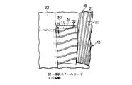
30は前記ビードコア12およびカーカス層18より軸方向内側のビード部13にそれぞれ配置されたコード補強層であり、これらのコード補強層30は少なくとも1枚の補強プライ、この実施形態では1枚の補強プライ31から構成されている。また、このコード補強層30(補強プライ31)内には波状(ジグザグ状)に屈曲するとともに、渦巻き状を呈しながら周方向に連続して延びる波状スチールコード32が埋設されているが、隣接する波状スチールコード32の巻きの子午線方向における基線L間距離は実質上同一である。そして、このようなコード補強層30によりビード部13は補強される。   Reference numerals 30 denote cord reinforcement layers disposed in the bead portion 13 axially inward of the bead core 12 and the carcass layer 18, respectively. These cord reinforcement layers 30 are at least one reinforcement ply, in this embodiment, one reinforcement. It consists of ply 31. Further, in the cord reinforcing layer 30 (reinforcing ply 31), a corrugated steel cord 32 that is bent in a wave shape (zigzag shape) and continuously extends in the circumferential direction while being spiral is embedded. The distance between the base lines L in the meridian direction of the winding of the corrugated steel cord 32 is substantially the same. The bead portion 13 is reinforced by such a cord reinforcing layer 30.

ここで、前述の実施形態においては、空気入りタイヤ11をトラック・バスに装着されるタイヤとして説明したが、この発明は、乗用車、航空機あるいは大型建設車両に装着されるタイヤに適用してもよい。また、前述の実施形態においては、空気入りタイヤ11をラジアルタイヤとして説明したが、この発明は、ベルト層が省略されている航空機用のバイアスタイヤ、あるいは、ベルト層の代わりにブレーカ層が配置されている通常のバイアスタイヤに適用することもできる。このようにカーカス層18の半径方向外側には少なくともトレッドが配置されている。   Here, in the above-described embodiment, the pneumatic tire 11 has been described as a tire mounted on a truck / bus. However, the present invention may be applied to a tire mounted on a passenger car, an aircraft, or a large construction vehicle. . In the above-described embodiment, the pneumatic tire 11 is described as a radial tire. However, in the present invention, an aircraft bias tire in which the belt layer is omitted, or a breaker layer is disposed instead of the belt layer. It can also be applied to normal bias tires. In this manner, at least the tread is disposed on the outer side in the radial direction of the carcass layer 18.

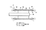
次に、前述のような空気入りタイヤ11は、例えば、以下に説明するようにして製造することができる。即ち、図3、4、5において、35は拡縮径可能で水平な軸線回りに回転可能な円筒状の成形ドラムであり、この成形ドラム35が図示していないサーボモータから回転駆動力を受けて軸線回りに回転しているとき、該成形ドラム35の前方に設置されたインナーライナー供給手段36から成形ドラム35にシート状のインナーライナー22を供給してその周囲に巻き付け、円筒状のインナーライナー22を成形する。     Next, the pneumatic tire 11 as described above can be manufactured, for example, as described below. That is, in FIGS. 3, 4 and 5, reference numeral 35 denotes a cylindrical forming drum which can be enlarged and reduced in diameter and rotated around a horizontal axis. The forming drum 35 receives a rotational driving force from a servo motor (not shown). When rotating around the axis, a sheet-like inner liner 22 is supplied to the forming drum 35 from the inner liner supplying means 36 installed in front of the forming drum 35 and wound around the inner liner 22 to form a cylindrical inner liner 22 Is molded.

次に、前記成形ドラム35(インナーライナー22)の軸方向両端部外側に前記波状スチールコード32が埋設されたリボン状体37を供給して、該成形ドラム35(インナーライナー22)の周囲に複数回巻き付け、該リボン状体37により円筒状をしたコード補強層30を成形するが、この成形ドラム35に供給するリボン状体37は、例えば、図4、5に示すようなリボン成形装置34により成形することができる。   Next, a ribbon-like body 37 in which the corrugated steel cord 32 is embedded is supplied to the outside of both ends in the axial direction of the forming drum 35 (inner liner 22), and a plurality of pieces are provided around the forming drum 35 (inner liner 22). The cord reinforcing layer 30 formed into a cylindrical shape is formed by winding the ribbon-shaped body 37. The ribbon-shaped body 37 supplied to the forming drum 35 is formed by, for example, a ribbon forming apparatus 34 as shown in FIGS. Can be molded.

図4、5において、38はモノフィラメントまたは撚り線からなるスチールコード39が多数回巻取られたボビンであり、このボビン38から巻出されたスチールコード39は直線状に延びながら前方に向かって走行し、ボビン38の前方(下流側)に設置された屈曲手段40に供給される。このとき、前記ボビン38には一定の制動力が付与されているため、ボビン38と屈曲手段40との間に張り渡されたスチールコード39には所定の内部張力が付与される。   4 and 5, 38 is a bobbin around which a steel cord 39 made of monofilament or stranded wire is wound many times. The steel cord 39 unwound from the bobbin 38 runs forward while extending linearly. Then, it is supplied to the bending means 40 installed in front of the bobbin 38 (downstream side). At this time, since a constant braking force is applied to the bobbin 38, a predetermined internal tension is applied to the steel cord 39 stretched between the bobbin 38 and the bending means 40.

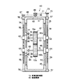
前記屈曲手段40は、図6に示すように、床面上に固定された前後が開放されているボックス状の支持フレーム41を有し、この支持フレーム41内には回転軸線が互いに平行で上下に離れた少なくとも一対、ここでは一対の平歯車からなるギア42が収納されている。前記支持フレーム41の左右に位置する両側壁には上下方向に延びる貫通したスライド孔43がそれぞれ形成され、これらスライド孔43の前後内面には上下方向に延びるガイドレール44がそれぞれ敷設されている。   As shown in FIG. 6, the bending means 40 has a box-shaped support frame 41 that is fixed on the floor surface and is open on the front and rear sides. A gear 42 composed of at least a pair separated from each other, here a pair of spur gears, is housed. Both side walls located on the left and right sides of the support frame 41 are respectively formed with through-slide holes 43 extending in the vertical direction, and guide rails 44 extending in the vertical direction are laid on the front and rear inner surfaces of the slide holes 43, respectively.

48、49は左右方向に離れて設けられた一対の上側、下側スライドプレートであり、これら上側、下側スライドプレート48、49は各スライド孔43に上下に離れてそれぞれ収納されるとともに、その前後面にそれぞれ固定された図示していないスライドベアリングが前記ガイドレール44に摺動可能に係合している。各上側スライドプレート48は、前記ギア42のうち、一側方のギア、ここでは上側ギア42aの水平な回転軸50の両端部をそれぞれ回転可能に支持する一方、各下側スライドプレート49は、前記ギア42のうち、他側方のギア、ここでは下側ギア42bの水平な回転軸51の両端部をそれぞれ回転可能に支持している。   48 and 49 are a pair of upper and lower slide plates that are provided apart in the left-right direction. These upper and lower slide plates 48 and 49 are respectively stored in the slide holes 43 apart from each other, and Slide bearings (not shown) fixed to the front and rear surfaces are slidably engaged with the guide rail 44. Each upper slide plate 48 rotatably supports one side gear of the gear 42, here both ends of the horizontal rotation shaft 50 of the upper gear 42a, while each lower slide plate 49 is Of the gear 42, the other side gear, here, both ends of the horizontal rotating shaft 51 of the lower gear 42b are rotatably supported.

54、55は支持フレーム41の側壁外面でその上下端部に取り付けられた一対の軸受56、57を介して該支持フレーム41にそれぞれ回転可能に支持された上下方向に延びるねじ軸であり、これらねじ軸54、55の軸方向(上下方向)上側部外周にはおねじ部58がそれぞれ形成される一方、その軸方向下側部外周には前記おねじ部58と逆ねじとなったおねじ部59がそれぞれ形成されている。   54 and 55 are screw shafts extending in the vertical direction and rotatably supported by the support frame 41 via a pair of bearings 56 and 57 attached to the upper and lower ends of the outer surface of the side wall of the support frame 41. A male screw portion 58 is formed on the outer periphery of the upper side in the axial direction (vertical direction) of the screw shafts 54 and 55, respectively, and a male screw portion that is reverse to the male screw portion 58 on the outer periphery of the lower side portion in the axial direction. 59 is formed.

63、64は各上側、下側スライドプレート48、49にそれぞれ固定された上側、下側ねじブロックであり、これら上側ねじブロック63には前記ねじ軸54、55のおねじ部58がそれぞれねじ込まれる一方、これら下側ねじブロック64には前記ねじ軸54、55のおねじ部59がそれぞれねじ込まれている。65は前記支持フレーム41の頂壁に取り付けられた単一の駆動モータであり、この駆動モータ65の出力軸に固定されたプーリ66と前記ねじ軸54の上端部に固定されたプーリ67との間にはタイミングベルト68が、また、駆動モータ65の出力軸に固定されたプーリ69と前記ねじ軸55の上端部に固定されたプーリ70との間にはタイミングベルト71がそれぞれ掛け渡されている。   63 and 64 are upper and lower screw blocks fixed to the upper and lower slide plates 48 and 49, respectively, and the male screw portions 58 of the screw shafts 54 and 55 are screwed into the upper screw blocks 63, respectively. On the other hand, male screw portions 59 of the screw shafts 54 and 55 are screwed into the lower screw blocks 64, respectively. Reference numeral 65 denotes a single drive motor attached to the top wall of the support frame 41. A pulley 66 fixed to the output shaft of the drive motor 65 and a pulley 67 fixed to the upper end of the screw shaft 54 are provided. A timing belt 68 is interposed between the pulley 69 fixed to the output shaft of the drive motor 65 and a pulley 70 fixed to the upper end portion of the screw shaft 55. Yes.

この結果、前記駆動モータ65が作動してねじ軸54、55が等速で回転すると、上側、下側スライドプレート48、49は、ガイドレール44にガイドされながら逆ねじであるおねじ部58、59によってそれぞれ逆方向に等距離だけ同時に移動し、互いに接近離隔する。そして、このような上下方向への接近離隔により、前記上側、下側スライドプレート48、49にそれぞれ支持されている上側、下側ギア42a、42bの回転軸線間距離が徐々に変化し、これにより、対向する上側、下側ギア42a、42bにおける外歯72a、72b間の距離が徐々に変化する。   As a result, when the drive motor 65 operates and the screw shafts 54 and 55 rotate at a constant speed, the upper and lower slide plates 48 and 49 are male screw portions 58 that are reverse screws while being guided by the guide rail 44, By 59, they move simultaneously by the same distance in the opposite directions and approach each other. Then, due to the approach and separation in the vertical direction, the distance between the rotation axes of the upper and lower gears 42a and 42b supported by the upper and lower slide plates 48 and 49, respectively, gradually changes. The distance between the external teeth 72a and 72b in the opposed upper and lower gears 42a and 42b gradually changes.

前述した上側、下側スライドプレート48、49、ねじ軸54、55、上側、下側ねじブロック63、64、駆動モータ65、プーリ66、67、69、70、タイミングベルト68、71は全体として、上側ギア42aの外歯72aと下側ギア42bの外歯72bとの間の距離を徐々に変化させることで、これらの食い込み量を調整することができる距離調整機構73を構成する。   The upper and lower slide plates 48 and 49, the screw shafts 54 and 55, the upper and lower screw blocks 63 and 64, the drive motor 65, the pulleys 66, 67, 69, and 70, and the timing belts 68 and 71, as a whole, By gradually changing the distance between the external teeth 72a of the upper gear 42a and the external teeth 72b of the lower gear 42b, a distance adjusting mechanism 73 capable of adjusting the amount of biting is configured.

77は片方(ここでは左方)の上側スライドプレート48の上面に固定された駆動モータであり、この駆動モータ77の出力軸に固定されたプーリ78と、上側ギア42aの回転軸50に固定されたプーリ79とはタイミングベルト80を介して連結されている。81は片方(左方)の下側スライドプレート49の下面に固定された駆動モータであり、この駆動モータ81の出力軸に固定されたプーリ82と、下側ギア42bの回転軸51に固定されたプーリ83とはタイミングベルト84を介して連結されている。   Reference numeral 77 denotes a drive motor fixed to the upper surface of one (here, the left) upper slide plate 48. The drive motor 77 is fixed to the pulley 78 fixed to the output shaft of the drive motor 77 and the rotary shaft 50 of the upper gear 42a. The pulley 79 is connected via a timing belt 80. Reference numeral 81 denotes a drive motor fixed to the lower surface of one (left) lower slide plate 49. The drive motor 81 is fixed to the pulley 82 fixed to the output shaft of the drive motor 81 and the rotary shaft 51 of the lower gear 42b. The pulley 83 is connected via a timing belt 84.

そして、前記駆動モータ(駆動源)77、81の駆動力を上側、下側ギア42a、42bに伝達すると、これら上側、下側ギア42a、42bは外歯72a、72b同士が互いに喰い込みながらこれらの間に周方向の所定の間隔を設けた状態で逆方向に等速度で回転する。前述した駆動モータ77、81、プーリ78、79、82、83、タイミングベルト80、84は全体として、前記一対のギア42に駆動力を付与してこれらギア42を逆方向に等速度(同一角速度)で駆動回転させる駆動機構85を構成する。   When the driving force of the drive motors (drive sources) 77 and 81 is transmitted to the upper and lower gears 42a and 42b, the upper and lower gears 42a and 42b are engaged with each other while the external teeth 72a and 72b bite each other. Rotate at a constant speed in the reverse direction with a predetermined circumferential interval between them. The drive motors 77, 81, pulleys 78, 79, 82, 83, and timing belts 80, 84 described above generally apply a drive force to the pair of gears 42 so that these gears 42 are at the same speed in the opposite direction (the same angular speed). ) Constitutes a drive mechanism 85 for driving and rotating.

また、これら駆動機構85によりギア42が回転されているとき、前記スチールコード39がギア42間に供給されると、該スチールコード39はギア42間を通過する際、外歯72a、72bに上下から押されて塑性変形しながら連続的に波状に屈曲し、これにより、該スチールコード39は鉛直面内において波状に屈曲した波状スチールコード32となる。   When the steel cord 39 is supplied between the gears 42 when the gear 42 is rotated by these drive mechanisms 85, the steel cord 39 moves up and down on the external teeth 72a and 72b when passing between the gears 42. The steel cord 39 is continuously bent in a wave shape while being plastically deformed, and the steel cord 39 becomes a wave-like steel cord 32 bent in a wave shape in the vertical plane.

そして、このような屈曲作業時において、前記距離調整機構73の作動により、対向する上側、下側ギア42a、42bを接近離隔させてこれらの回転軸線間距離を徐々に変化させる、この実施形態では、これら上側、下側ギア42a、42bを徐々に接近させ、これらギア42a、42bにおける外歯72a、72b間の距離を徐々に減少させる。この結果、前述のようなギア42a、42b間を通過することで成形される波状スチールコード32の振幅aは、該波状スチールコード32の長手方向に沿って徐々に増大する。逆に、前記上側、下側ギア42a、42bを徐々に離隔させると、波状スチールコード32の振幅aは徐々に減少する。   In such a bending operation, the distance adjustment mechanism 73 is actuated to move the upper and lower gears 42a, 42b facing each other closer to each other and gradually change the distance between the rotation axes. The upper and lower gears 42a and 42b are gradually approached, and the distance between the external teeth 72a and 72b in the gears 42a and 42b is gradually reduced. As a result, the amplitude a of the corrugated steel cord 32 formed by passing between the gears 42 a and 42 b as described above gradually increases along the longitudinal direction of the corrugated steel cord 32. Conversely, when the upper and lower gears 42a, 42b are gradually separated, the amplitude a of the waved steel cord 32 gradually decreases.

このときの前記波状スチールコード32の振幅a(基線Lから波の最高点までの距離)はその成形時における前記外歯72a、72b同士の喰い込み量の 1/2であって、前記外歯72a、72b間距離の変化に対応して徐々に変化する。一方、波状スチールコード32の波長λは上側、下側ギア42a、42bの回転軸線間の中点を通る円上での隣接する2つの外歯72a、72b間の周方向距離と同一であって、いずれの長手方向位置においても一定である(振幅a、波長λについては図7参照)。   At this time, the amplitude a of the corrugated steel cord 32 (distance from the base line L to the highest point of the wave) is half of the amount of biting between the external teeth 72a and 72b at the time of molding, and the external teeth It changes gradually corresponding to the change in the distance between 72a and 72b. On the other hand, the wavelength λ of the corrugated steel cord 32 is the same as the circumferential distance between two adjacent external teeth 72a, 72b on a circle passing through the midpoint between the rotation axes of the upper and lower gears 42a, 42b. These are constant in any longitudinal position (see FIG. 7 for amplitude a and wavelength λ).

前述した支持フレーム41、ギア42、距離調整機構73、駆動機構85は全体として、外歯72a、72b間の距離を徐々に変化させながら直線状に延びるスチールコード39を上側、下側ギア42a、42b間を通過させることで、振幅aが長手方向に徐々に変化する波状スチールコード32を成形する前記屈曲手段40を構成する。ここで、前述の振幅aは、連続的に変化してもよく、あるいは、1回または複数回の巻き付けの度に段階的に変化してもよい。   The support frame 41, the gear 42, the distance adjustment mechanism 73, and the drive mechanism 85 described above as a whole have the steel cord 39 that extends linearly while gradually changing the distance between the external teeth 72a and 72b. By passing between 42b, the said bending means 40 which shape | molds the corrugated steel cord 32 from which the amplitude a changes gradually in a longitudinal direction is comprised. Here, the above-mentioned amplitude a may change continuously, or may change in steps every time one or more times are wound.

そして、このようなギア42、距離調整機構73、駆動機構85を有する屈曲手段40を用いれば、振幅aが徐々に変化する波状スチールコード32を後述の巻き付けに先立って容易かつ高精度で製作することができる。また、前述のようにギア42を平歯車から構成するとともに、その回転軸線を互いに平行としたので、簡単な構造でありながら前述のように振幅aが徐々に変化する波状スチールコード32を容易かつ高精度で製作することができる。   If the bending means 40 having the gear 42, the distance adjusting mechanism 73, and the drive mechanism 85 is used, the corrugated steel cord 32 with the amplitude a gradually changing can be manufactured easily and with high accuracy prior to winding described later. be able to. Further, since the gear 42 is constituted by a spur gear as described above and the rotation axes thereof are parallel to each other, the corrugated steel cord 32 in which the amplitude a is gradually changed as described above can be obtained easily and easily. Can be manufactured with high accuracy.

なお、前述の実施形態においては、一対のギア42によって波状スチールコード32を成形するようにしたが、この発明においては、外縁部同士が上下に重なり合う水平な一対の円板を設置するとともに、下側の円板の上面外縁部に上方に突出する多数のピンを周方向に等距離離して固着する一方、上側の円板の下面外縁部に下方に突出する多数のピンを周方向に等距離離して固着し、これら両円板を回転軸線回りに逆方向に回転させているとき、互いに侵入し合うピン間に直線状のスチールコードを喰い込ませて連続的に波状に屈曲させることにより、波状スチールコードを成形するようにしてもよい。   In the above-described embodiment, the corrugated steel cord 32 is formed by the pair of gears 42. However, in the present invention, a pair of horizontal disks in which the outer edges overlap with each other are installed and A number of pins protruding upward are fixed to the outer edge of the upper surface of the side disk at equal distances in the circumferential direction, while a number of pins protruding downward to the outer edge of the lower surface of the upper disk are fixed at the same distance in the circumferential direction. When these two discs are fixed apart and rotated in the opposite direction around the axis of rotation, a straight steel cord is engulfed between the pins that invade each other and bent continuously in a wave shape, A corrugated steel cord may be formed.

この場合においても、両円板の回転軸線間の距離を徐々に変化させることで、これらピン同士の食い込み量を調整することができるため、振幅が徐々に変化する波状スチールコードを容易に成形することができる。また、前述の実施形態においては、ギア42として平歯車を用いたが、この発明においては、スチールコード39の径が歯幅に対して充分に小さいときには、ギアとしてすぐばかさ歯車等を用いることができる。さらに、この発明においては、前記屈曲手段におけるギアの回転軸線が鉛直方向に平行となるよう、屈曲手段を横置きとしてもよい。   Even in this case, the amount of biting between these pins can be adjusted by gradually changing the distance between the rotation axes of both disks, so that a corrugated steel cord whose amplitude gradually changes can be easily formed. be able to. In the above-described embodiment, a spur gear is used as the gear 42. However, in the present invention, when the diameter of the steel cord 39 is sufficiently small with respect to the tooth width, a bevel gear or the like is immediately used as the gear. Can do. Further, in the present invention, the bending means may be placed horizontally so that the rotation axis of the gear in the bending means is parallel to the vertical direction.

再び、図4、5において、90は屈曲手段40の前方に設置されたフリー回転可能な横倒しローラであり、この横倒しローラ90の回転軸線はギア42の回転軸線に平行である。そして、屈曲手段40により成形された波状スチールコード32は前記横倒しローラ90の外周に約 1/4周だけ接触した後、方向転換され下方に向かって走行する。このとき、鉛直面内において波状に屈曲していた波状スチールコード32は屈曲手段40と横倒しローラ90との間で90度だけ捻られ、水平面内において波状に屈曲するようになる。   4 and 5, reference numeral 90 denotes a free-turning sideways roller installed in front of the bending means 40, and the rotation axis of the sideways roller 90 is parallel to the rotation axis of the gear 42. Then, after the corrugated steel cord 32 formed by the bending means 40 contacts the outer periphery of the sideways roller 90 by about 1/4 turn, the direction is changed and the vehicle runs downward. At this time, the corrugated steel cord 32 bent in a wavy shape in the vertical plane is twisted by 90 degrees between the bending means 40 and the sideways roller 90 and bent in a wavy shape in the horizontal plane.

91は横倒しローラ90より前方で該横倒しローラ90より下方に設置された複数のローラ92からなるローラ群であり、このローラ群91を構成するローラ92のうち、少なくとも1個のローラ92は図示していない駆動モータにより駆動回転される。そして、前述のように横倒しローラ90によって90度だけ捻られた波状スチールコード32は、ローラ群91を構成するローラ92の外周に次々に接触しながら前方に向かって走行するが、このとき、ローラ92の周速は屈曲手段40から排出されたときの波状スチールコード32の走行速度と等速であるため、波状スチールコード32は振幅a、波長λが変化することなく前方に向かって供給される。   91 is a roller group composed of a plurality of rollers 92 disposed in front of the roll-down roller 90 and below the roll-down roller 90, and at least one of the rollers 92 constituting the roller group 91 is illustrated. It is driven and rotated by a drive motor that is not. Then, as described above, the corrugated steel cord 32 that is twisted by 90 degrees by the sideways roller 90 runs forward while in contact with the outer periphery of the rollers 92 constituting the roller group 91 one after another. Since the peripheral speed of 92 is equal to the traveling speed of the corrugated steel cord 32 when discharged from the bending means 40, the corrugated steel cord 32 is supplied forward without changing the amplitude a and the wavelength λ. .

93はローラ群91の前方に設置された一対の被覆ローラ94からなる被覆手段であり、これらの被覆ローラ94はフリー回転可能で、上下に離れて配置されている。そして、これら被覆ローラ94間に前述のように振幅aが徐々に変化、ここでは、振幅aが徐々に増大する波状スチールコード32、および、該波状スチールコード32を上下から挟持する薄肉ゴムリボン95が供給されると、前記薄肉ゴムリボン95は被覆ローラ94に押されて波状スチールコード32を間に挟持しながら互いに密着し、波状スチールコード32を両側から被覆する。   93 is a covering means composed of a pair of covering rollers 94 installed in front of the roller group 91. These covering rollers 94 are free to rotate and are arranged apart from each other in the vertical direction. The amplitude a gradually changes between the covering rollers 94 as described above. Here, the corrugated steel cord 32 in which the amplitude a gradually increases, and the thin rubber ribbon 95 sandwiching the corrugated steel cord 32 from above and below are provided. When supplied, the thin rubber ribbon 95 is pressed by the covering roller 94 and is brought into close contact with the corrugated steel cord 32 while sandwiching the corrugated steel cord 32 therebetween, thereby covering the corrugated steel cord 32 from both sides.

このようにして波状スチールコード32、薄肉ゴムリボン95からなる前記リボン状体37が成形される。ここで、前記薄肉ゴムリボン95は波状スチールコード32の振幅aの2倍より若干幅広で、かつ、その幅が波状スチールコード32における振幅aの変化に追従するよう、ここではその幅が徐々に大となるよう成形された帯状未加硫ゴムから構成されている。   In this way, the ribbon-like body 37 composed of the corrugated steel cord 32 and the thin rubber ribbon 95 is formed. Here, the thin rubber ribbon 95 is slightly wider than twice the amplitude a of the corrugated steel cord 32, and the width gradually increases so that the width follows the change of the amplitude a in the corrugated steel cord 32. It is comprised from the strip | belt-shaped unvulcanized rubber shape | molded so that it may become.

前述した屈曲手段40、横倒しローラ90、ローラ群91、被覆手段93は全体として、供給された直線状のスチールコード39を波状に屈曲させるとともに、波状となった波状スチールコード32を薄肉ゴムリボン95でコーティングすることで、波状スチールコード32が埋設されたリボン状体37を成形する前記リボン成形装置34を構成する。   The bending means 40, the roll-over roller 90, the roller group 91, and the covering means 93 are bent as a whole with the supplied straight steel cord 39 in a wave shape, and the wavy steel cord 32 with a thin rubber ribbon 95 is bent. By coating, the ribbon forming apparatus 34 for forming the ribbon-like body 37 in which the corrugated steel cord 32 is embedded is configured.

100は被覆手段93の前方に設置された送り出し機構であり、この送り出し機構 100は前記ローラ92に平行な複数のローラ 101から構成されるとともに、少なくとも1個のローラ 101は図示していない駆動モータにより一定の回転速度で回転するよう、即ち周速が前記被覆ローラ94から排出されたリボン状体37の走行速度と等速度となるよう駆動されている。そして、この送り出し機構 100のローラ 101の外周には前記リボン状体37が次々と接触しながら走行し、これにより、該リボン状体37は送り出し機構 100から、内部に埋設された波状スチールコード32の振幅a、波長λが変化することなく、前記成形ドラム35に向かって供給される。    100 is a delivery mechanism installed in front of the covering means 93. This delivery mechanism 100 is composed of a plurality of rollers 101 parallel to the roller 92, and at least one roller 101 is a drive motor (not shown). , So that the peripheral speed is equal to the traveling speed of the ribbon 37 discharged from the covering roller 94. The ribbon-like body 37 travels in contact with the outer periphery of the roller 101 of the delivery mechanism 100 one after another, whereby the ribbon-like body 37 is moved from the delivery mechanism 100 to the corrugated steel cord 32 embedded therein. Are supplied toward the forming drum 35 without changing the amplitude a and the wavelength λ.

102は前記送り出し機構 100と成形ドラム35との間に設置された綾振り機構であり、この綾振り機構 102は前記成形ドラム35の回転軸線に平行に延びるガイド体 103と、該ガイド体 103に移動可能に支持され、前記成形ドラム35に向かって走行するリボン状体37の位置(成形ドラム35の軸方向での位置)を規制する可動ガイド 104と、該可動ガイド 104をガイド体 103に沿って移動させることでリボン状体37を成形ドラム35の回転軸線方向に綾振る、図示していないねじ機構、駆動モータ等を有する駆動機構から構成されている。    Reference numeral 102 denotes a traverse mechanism installed between the feed mechanism 100 and the forming drum 35. The traverse mechanism 102 includes a guide body 103 extending parallel to the rotation axis of the forming drum 35, and the guide body 103. A movable guide 104 that is movably supported and regulates the position of the ribbon-shaped body 37 that travels toward the molding drum 35 (the position of the molding drum 35 in the axial direction), and the movable guide 104 along the guide body 103. And a drive mechanism having a screw mechanism (not shown), a drive motor, and the like that traverse the ribbon-like body 37 in the rotation axis direction of the forming drum 35 by moving the ribbon-like body 37.

そして、送り出し機構 100から成形ドラム35にリボン状体37が供給されているとき、綾振り機構 102の可動ガイド 104がガイド体 103に沿って一定速度で移動すると、成形ドラム35の周囲にはリボン状体37が複数回軸方向外側から軸方向内側に向かって螺旋状に巻き付けられ、該成形ドラム35の外側に円筒状のコード補強層30が成形される。このようにしてコード補強層30が成形されると、前記リボン状体37を幅方向に切断する。このようにリボン状体37(波状スチールコード32)を螺旋状に複数回巻き付けることでコード補強層30を成形するようにすれば、コード補強層30を簡単かつ安価でありながら高能率で容易に成形することができる。   When the ribbon-shaped body 37 is supplied from the feed mechanism 100 to the forming drum 35, the movable guide 104 of the traverse mechanism 102 moves at a constant speed along the guide body 103, and the ribbon around the forming drum 35 The cylindrical body 37 is spirally wound from the outer side in the axial direction a plurality of times toward the inner side in the axial direction, and the cylindrical cord reinforcing layer 30 is formed outside the forming drum 35. When the cord reinforcing layer 30 is formed in this way, the ribbon-like body 37 is cut in the width direction. Thus, if the cord reinforcing layer 30 is formed by winding the ribbon-like body 37 (the corrugated steel cord 32) spirally a plurality of times, the cord reinforcing layer 30 can be easily and inexpensively easily and highly efficiently. Can be molded.

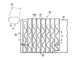
ここで、リボン状体37内に埋設される波状スチールコード32は、前述のような屈曲手段40によりその振幅aが徐々に増大するよう成形されており、また、このように成形された波状スチールコード32は、屈曲手段40により成形されてから成形ドラム35に巻き付けられるまでの間、その振幅a、波長λが変化することなく搬送されるので、屈曲手段40により成形された波状スチールコード32(リボン状体37)を送り出し機構 100から綾振り機構 102によって綾振りながら成形ドラム35にそのまま供給して複数回巻き付けると、前記振幅aは成形ドラム35の軸方向外側から軸方向内側に向かうに従い大と、即ち、後述するビードコア12のセット位置P(図3、5、7参照)に最も近接した位置で最小となり、該セット位置Pから軸方向に離隔するに従い徐々に増大する。   Here, the corrugated steel cord 32 embedded in the ribbon-shaped body 37 is formed so that the amplitude a gradually increases by the bending means 40 as described above, and the corrugated steel formed in this way. Since the cord 32 is conveyed without being changed in the amplitude a and the wavelength λ from the time when it is formed by the bending means 40 until it is wound around the forming drum 35, the corrugated steel cord 32 ( When the ribbon-shaped body 37) is supplied as it is to the forming drum 35 while being traversed by the traversing mechanism 102 from the feed mechanism 100 and wound a plurality of times, the amplitude a increases as it goes from the outside in the axial direction to the inside in the axial direction. That is, it becomes the minimum at a position closest to a set position P (see FIGS. 3, 5, 7) of the bead core 12 to be described later, and gradually increases from the set position P in the axial direction. Increase.

これにより、成形ドラム35上に成形されたコード補強層30を構成する波状スチールコード32の振幅aは前記ビードコア12のセット位置Pから軸方向に離隔するに従い徐々に大となるよう調節される。前述した送り出し機構 100、綾振り機構 102、成形ドラム35を駆動するサーボモータは全体として、波状スチールコード32を前記成形ドラム35にそのまま供給して複数回巻き付けることで、成形ドラム35上に該波状スチールコード32の振幅aがビードコア12のセット位置Pから軸方向に離隔するに従い大となったコード補強層30を成形するコード供給手段 105を構成する。   As a result, the amplitude a of the corrugated steel cord 32 constituting the cord reinforcing layer 30 formed on the forming drum 35 is adjusted to gradually increase as the distance from the set position P of the bead core 12 increases in the axial direction. As a whole, the servo motor for driving the feeding mechanism 100, the traversing mechanism 102, and the forming drum 35 is supplied to the forming drum 35 as it is and wound around the forming drum 35 by supplying the corrugated steel cord 32 as it is. A cord supplying means 105 for forming the cord reinforcing layer 30 in which the amplitude “a” of the steel cord 32 becomes larger in the axial direction from the set position P of the bead core 12 is configured.

なお、前述の実施形態においては、振幅aが徐々に大となる波状スチールコード32(リボン状体37)を成形ドラム35の軸方向外側から軸方向内側に向かって巻き付けるようにしたが、この発明においては、振幅が徐々に小となる波状スチールコードを成形ドラムの軸方向内側から軸方向外側に向かって巻き付けることで、波状スチールコードの振幅がビードコアのセット位置から軸方向に離隔するに従い大となったコード補強層を成形するようにしてもよい。そして、このように振幅が徐々に小となるスチールコードは、前述のように上側、下側ギアの回転軸線同士を徐々に離隔させることで成形することができる。   In the above-described embodiment, the wavy steel cord 32 (ribbon-like body 37) whose amplitude a gradually increases is wound from the outside in the axial direction of the forming drum 35 toward the inside in the axial direction. In this case, the wavy steel cord having a gradually decreasing amplitude is wound from the inner side in the axial direction of the forming drum toward the outer side in the axial direction, so that the amplitude of the wavy steel cord increases as the distance from the set position of the bead core increases in the axial direction. The formed cord reinforcing layer may be formed. The steel cord having a gradually reduced amplitude can be formed by gradually separating the rotation axes of the upper and lower gears as described above.

ここで、前述のように振幅aが徐々に大となる波状スチールコード32(リボン状体37)を用いながら、前述のように隣接する波状スチールコード32の基線L間距離を実質上同一としようとすると、セット位置Pに近接した位置では、セット位置Pから軸方向に離隔した位置におけるリボン状体37の幅に比較して、リボン状体37の幅が狭いため、図7に示すようにリボン状体37の側端間に間隙 106が発生するが、このような間隙 106はセット位置Pから離隔するに徐々に狭くなる。そして、このように構成したときには、空気入りタイヤ11となったときでも、隣接する波状スチールコード32の基線L間距離を実質上同一とすることができ、コード補強層30における波状スチールコード32の分布が均一となって、コード補強層30による補強効果が向上する。   Here, as described above, while using the corrugated steel cord 32 (ribbon-shaped body 37) with the amplitude a gradually increasing, the distance between the base lines L of the adjacent corrugated steel cords 32 is made substantially the same as described above. Then, at the position close to the set position P, the width of the ribbon-shaped body 37 is narrower than the width of the ribbon-shaped body 37 at a position spaced apart from the set position P in the axial direction. A gap 106 is generated between the side edges of the ribbon-like body 37, and the gap 106 is gradually narrowed away from the set position P. And when comprised in this way, even when it becomes the pneumatic tire 11, the distance between the base lines L of the adjacent corrugated steel cord 32 can be made substantially the same, and the corrugated steel cord 32 in the cord reinforcement layer 30 can be made the same. The distribution becomes uniform, and the reinforcing effect of the cord reinforcing layer 30 is improved.

なお、前述の実施形態においては、1本の波状スチールコード32を薄肉ゴムリボン95により被覆してリボン状体37を成形し、該リボン状体37を成形ドラム35に巻き付けるようにしたが、この発明においては、少数本、例えば2〜5本の波状スチールコードを引き揃えた後、薄肉ゴムリボンでこれら波状スチールコードを被覆してリボン状体を成形し、このようなリボン状体を成形ドラムに巻き付けるようにしてもよく、あるいは、1本または少数本の波状スチールコードを裸のままで、即ち、ゴム被覆することなく、さらには、1本の波状スチールコードの周囲を等厚のゴムで被覆した後、成形ドラムに供給して巻き付けるようにしてもよい。   In the above-described embodiment, the single corrugated steel cord 32 is covered with the thin rubber ribbon 95 to form the ribbon-shaped body 37, and the ribbon-shaped body 37 is wound around the molding drum 35. , After arranging a small number of, for example, 2-5 corrugated steel cords, the corrugated steel cords are covered with a thin rubber ribbon to form a ribbon-shaped body, and the ribbon-shaped body is wound around a molding drum. Alternatively, one or a small number of corrugated steel cords may be left bare, that is, without being covered with rubber, and further, the circumference of one corrugated steel cord may be coated with an equal thickness of rubber. Then, it may be supplied to the forming drum and wound.

さらに、前述の実施形態においては、波状スチールコード32(リボン状体37)を成形ドラム35に螺旋状に複数回巻き付けるようにしたが、この発明においては、波状スチールコードを成形ドラムに1周より若干少ない角度だけ実質上周方向に巻き付けた後、斜めに残余の角度だけ巻き付けて波状スチールコードを軸方向内側に所定距離だけずらす作業を複数回繰り返すことで、成形ドラムに波状スチールコードを複数回巻き付けるようにしてもよい。そして、前述のように成形ドラムへのリボン状体の巻き付け時、リボン状体(波状スチールコード)を成形ドラムの回転軸線に平行な直線に沿って綾振り誘導するだけで充分であるため、誘導制御は容易である。   Furthermore, in the above-described embodiment, the wavy steel cord 32 (ribbon-like body 37) is wound around the forming drum 35 a plurality of times in a spiral manner. However, in this invention, the wavy steel cord is wound around the forming drum from one turn. After wrapping in the circumferential direction substantially a little angle, then winding the slanted remaining angle diagonally and shifting the corrugated steel cord by a predetermined distance inward in the axial direction is repeated multiple times to form the corrugated steel cord multiple times on the forming drum. You may make it wind. As described above, when winding the ribbon-shaped body around the forming drum, it is sufficient to guide the ribbon-shaped body (the corrugated steel cord) along the straight line parallel to the rotation axis of the forming drum. Control is easy.

再び、図3、4、5において、 110は成形ドラム35の前方に設置されたカーカス供給手段であり、このカーカス供給手段 110は成形ドラム35に対するインナーライナー22、コード補強層30(波状スチールコード32)の巻き付けが終了すると、シート状のカーカスプライ21を成形ドラム35(インナーライナー22、コード補強層30)の外側に供給してその周囲に巻き付け、円筒状のカーカス層18を成形する。   3, 4, and 5, reference numeral 110 denotes a carcass supply means installed in front of the forming drum 35. The carcass supply means 110 includes an inner liner 22 and a cord reinforcing layer 30 (corrugated steel cord 32) with respect to the forming drum 35. Is finished, the sheet-like carcass ply 21 is supplied to the outside of the forming drum 35 (the inner liner 22 and the cord reinforcing layer 30) and wound around it to form the cylindrical carcass layer 18.

次に、図示していない縮径手段によりセット位置Pより軸方向外側のカーカス層18を絞り込んで仮想線で示すように縮径させた後、ビードコア供給手段 111によりフィラー19付きビードコア12を、カーカス層18の軸方向両端部外側に位置するセット位置Pに供給、ここでは、前記縮径によりカーカス層18に形成された段差まで搬送してそれぞれセットする。   Next, after reducing the diameter of the carcass layer 18 axially outside the set position P by the diameter reducing means (not shown) and reducing the diameter as shown by the phantom line, the bead core 12 with the filler 19 is The material is supplied to a set position P located outside the both ends in the axial direction of the layer 18, and here, it is transported to the step formed in the carcass layer 18 by the reduced diameter and set.

次に、ビードコア12より軸方向外側のカーカス層18を図示していない折返し機構により図8に示すようにビードコア12回りに折り返した後、図4に示すサイド供給手段 112により成形ドラム35(カーカス層18)の外側にシート状のサイドトレッド26を供給して巻き付け、図8に示すような円筒状のサイドトレッド26を成形する。   Next, the carcass layer 18 axially outside the bead core 12 is folded around the bead core 12 as shown in FIG. 8 by a folding mechanism (not shown), and then the forming drum 35 (carcass layer) is formed by the side supply means 112 shown in FIG. A sheet-like side tread 26 is supplied and wound around the outer side of 18) to form a cylindrical side tread 26 as shown in FIG.

この結果、成形ドラム35の周囲に、インナーライナー22、コード補強層30、カーカス層18、ビードコア12、フィラー19、サイドトレッド26を有する円筒状のタイヤ中間体 113(グリーンケース)が成形される。なお、コード補強層30が空気入りタイヤ11において折返し部17の軸方向外側に配置される場合には、カーカス層18の折返し後にリボン状体37を巻き付けてコード補強層30を成形することになる。   As a result, a cylindrical tire intermediate body 113 (green case) having the inner liner 22, the cord reinforcing layer 30, the carcass layer 18, the bead core 12, the filler 19, and the side tread 26 is formed around the forming drum 35. When the cord reinforcing layer 30 is disposed on the axially outer side of the folded portion 17 in the pneumatic tire 11, the cord reinforcing layer 30 is formed by winding the ribbon-like body 37 after the carcass layer 18 is folded. .

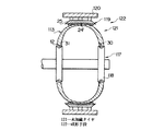
次に、タイヤ中間体 113を図示していない搬送手段により成形ドラム35から図9に示すシェーピングドラム 117まで搬送して、シェーピングドラム 117のビードロック機構 118により半径方向内側から把持した後、ビードロック機構 118を互いに接近させるとともに、タイヤ中間体 113内にエアを供給し、タイヤ中間体 113を略トロイダル状に膨出変形させる。このとき、図示していないバンド成形ドラムによって成形され、ベルト層24およびトップトレッド25からなるベルト・トレッドバンド 119を、搬送手段 120によりタイヤ中間体 113の半径方向外側まで搬送してタイヤ中間体 113の半径方向外側に貼付け略トロイダル状を呈する未加硫タイヤ 121を成形する。   Next, the tire intermediate body 113 is conveyed from the forming drum 35 to the shaping drum 117 shown in FIG. 9 by conveyance means (not shown), and is gripped from the radially inner side by the bead lock mechanism 118 of the shaping drum 117, and then the bead lock. While the mechanisms 118 are brought close to each other, air is supplied into the tire intermediate 113 to cause the tire intermediate 113 to bulge and deform in a substantially toroidal shape. At this time, a belt tread band 119 formed by a band forming drum (not shown) and including the belt layer 24 and the top tread 25 is conveyed to the radially outer side of the tire intermediate 113 by the conveying means 120, and the tire intermediate 113 is conveyed. An unvulcanized tire 121 having a substantially toroidal shape is attached to the outer side in the radial direction of the tire.

前述したシェーピングドラム 117、搬送手段 120は全体として、タイヤ中間体 113を略トロイダル状に膨出変形させるとともに、該タイヤ中間体 113の半径方向外側に少なくともトレッド、ここではベルト層24およびトップトレッド25を貼付けて未加硫タイヤ 121を成形する成形手段 122を構成する。なお、このような未加硫タイヤはシングルステージ形式のドラムによって成形してもよく、この場合には、該ドラムが成形ドラムと成形手段とを兼用することになる。また、この発明においては、シェーピングドラムにおいてカーカス層をビードコア回りに折り返すようにしてもよい。   The above-described shaping drum 117 and conveying means 120 as a whole cause the tire intermediate body 113 to bulge and deform in a substantially toroidal shape, and at least the tread, here the belt layer 24 and the top tread 25, radially outward of the tire intermediate body 113. The forming means 122 for forming the unvulcanized tire 121 is configured by pasting. Such an unvulcanized tire may be formed by a single stage type drum. In this case, the drum serves as both a forming drum and a forming means. In the present invention, the carcass layer may be folded around the bead core in the shaping drum.

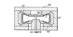
さらに、前記未加硫タイヤがバイアスタイヤ用である場合には、成形ドラム上のタイヤ中間体にブレーカ層およびトレッド、または、トレッドのみを貼付けて未加硫タイヤを成形した後、該未加硫タイヤを略トロイダル状に膨出変形させる。このようにして未加硫タイヤ 121が成形されると、該未加硫タイヤ 121を図示していない搬送手段により、図10に示すような下サイドモールド 125、上サイドモールド 126、セクターモールド 127を備えた加硫手段 128に搬入し、該加硫手段 128により加硫してトロイダル状をした空気入りタイヤ11とする。なお、前記未加硫タイヤ 121は上下に2分割されたモールドを有する加硫手段によって加硫するようにしてもよい。   Further, when the unvulcanized tire is for a bias tire, after molding the unvulcanized tire by pasting only the breaker layer and the tread or the tread to the tire intermediate body on the molding drum, the unvulcanized tire is molded. The tire bulges and deforms in a substantially toroidal shape. When the unvulcanized tire 121 is formed in this way, the lower side mold 125, the upper side mold 126, and the sector mold 127 as shown in FIG. The pneumatic tire 11 is carried into the vulcanizing means 128 provided and vulcanized by the vulcanizing means 128 to form a toroidal shape. The unvulcanized tire 121 may be vulcanized by a vulcanizing means having a mold that is divided into two vertically.

ここで、前述したタイヤ中間体 113(未加硫タイヤ 121)の略トロイダル状への変形によりコード補強層30が円筒状から略鍔状に変形すると、該コード補強層30はビードコア12から離隔するに従い(半径方向外側の部位ほど)周方向に大きく引き伸ばされるため、コード補強層30を構成する波状スチールコード32は振幅aはビードコア12から離隔するに従い小さくなり、波状スチールコード32の振幅aがコード補強層30全体で、特に半径方向に見たとき、かなり不均一となる。   Here, when the cord reinforcing layer 30 is deformed from a cylindrical shape to a substantially bowl shape by the deformation of the tire intermediate body 113 (unvulcanized tire 121) described above into a substantially toroidal shape, the cord reinforcing layer 30 is separated from the bead core 12. Therefore, the wave-like steel cord 32 constituting the cord reinforcing layer 30 has a smaller amplitude a as the distance from the bead core 12 increases, and the wave-like steel cord 32 has an amplitude a. The entire reinforcing layer 30 is considerably uneven, especially when viewed in the radial direction.

このため、この実施形態においては、前述のように振幅aが徐々に大となる波状スチールコード32を円筒状の成形ドラム35にそのまま複数回巻き付けることで、該波状スチールコード32の振幅aをビードコア12のセット位置Pから軸方向に離隔するに従い大としたのである。これにより、前述した波状スチールコード32の振幅減少と振幅増大とが相殺し合って空気入りタイヤ11における波状スチールコード32の振幅aがコード補強層30全体で、特に半径方向に見て近似(均一化)し、タイヤ性能が向上するのである。   Therefore, in this embodiment, as described above, the corrugated steel cord 32 having the gradually increasing amplitude a is wound around the cylindrical forming drum 35 a plurality of times as it is, so that the amplitude a of the corrugated steel cord 32 is bead core. The distance from the 12 set positions P increases in the axial direction. As a result, the amplitude decrease and the amplitude increase of the corrugated steel cord 32 described above cancel each other, and the amplitude a of the corrugated steel cord 32 in the pneumatic tire 11 is approximated (uniformly) in the entire cord reinforcing layer 30, particularly when viewed in the radial direction. Tire performance is improved.

また、直線状に延びるスチールコード39を屈曲させるだけで徐々に振幅aが増大する波状スチールコード32を製造しているため、該スチールコードに過剰な変形を生じさせることはなく、この結果、耐久性の高いコード補強層30を成形することができるとともに、予め屈曲させた波状スチールコード32をそのまま巻き付けるようにしているため、巻付け直後における波状スチールコード32の振幅aをコード補強層30の各部で高精度とすることができる。   Further, since the corrugated steel cord 32 whose amplitude a gradually increases by bending the steel cord 39 extending linearly is manufactured, the steel cord is not excessively deformed. The cord reinforcing layer 30 having high properties can be formed and the pre-bent corrugated steel cord 32 is wound as it is, so that the amplitude a of the corrugated steel cord 32 immediately after winding is determined for each part of the cord reinforcing layer 30. With high accuracy.

しかも、スチールコードは円筒状の成形ドラム35に対する巻付けに先立って振幅aが徐々に変化するよう波状に屈曲されるので、巻付けの際、波状スチールコード32を成形ドラム35の軸線に平行な直線に沿って綾振り誘導するだけで充分であり、この結果、巻付けの際の制御が簡単となるとともに、作業能率を向上させることもできる。   Moreover, since the steel cord is bent into a wave shape so that the amplitude a gradually changes prior to winding around the cylindrical forming drum 35, the corrugated steel cord 32 is parallel to the axis of the forming drum 35 during winding. It is sufficient to guide the traverse along the straight line, and as a result, the control at the time of winding becomes simple and the work efficiency can be improved.

ここで、前述のように振幅aが徐々に増大する波状スチールコード32(リボン状体37)を成形ドラム35に巻き付ける場合、ビードコア12のセット位置Pに最も近接する位置に巻き付けられている波状スチールコード32の振幅aを、空気入りタイヤ11の状態でのコード補強層30の半径方向最外側に位置する波状スチールコード32の振幅aとほぼ同一とすれば、容易にコード補強層30全体における波状スチールコード32の振幅aを強力に均一化することができるので、好ましい。   Here, when the corrugated steel cord 32 (ribbon-shaped body 37) whose amplitude a gradually increases as described above is wound around the forming drum 35, the corrugated steel wound at the position closest to the set position P of the bead core 12 is wound. If the amplitude a of the cord 32 is substantially the same as the amplitude a of the corrugated steel cord 32 located on the radially outermost side of the cord reinforcing layer 30 in the state of the pneumatic tire 11, the corrugated shape in the entire cord reinforcing layer 30 can be easily obtained. The amplitude a of the steel cord 32 can be strongly uniformed, which is preferable.

なお、前述の実施形態においては、コード補強層30をビードコア12より軸方向内側のビード部13に配置したが、この発明においては、図11に示すように、コード補強層30の代わりに、コード補強層 131を、ビードコア12より軸方向外側のビード部13においてカーカス層18の折返し部17に重ね合わせながら配置してもよい。この場合には、成形ドラム35にカーカス層18を成形するとともに、前記セット位置Pにビードコア12をセットした後、詳しくは、成形されたカーカス層18をビードコア12の回りに折返した後に、リボン状体37を巻き付けてコード補強層 131を成形することになる。     In the above-described embodiment, the cord reinforcing layer 30 is arranged in the bead portion 13 in the axial direction inner side than the bead core 12. However, in the present invention, as shown in FIG. The reinforcing layer 131 may be disposed while being superimposed on the folded portion 17 of the carcass layer 18 in the bead portion 13 axially outside the bead core 12. In this case, after the carcass layer 18 is formed on the forming drum 35 and the bead core 12 is set at the set position P, more specifically, after the formed carcass layer 18 is folded around the bead core 12, a ribbon shape is formed. The cord reinforcement layer 131 is formed by winding the body 37.

さらに、この発明においては、ビードコア12の軸方向内側にコード補強層30を、軸方向外側にコード補強層 131を共に配置してもよい。また、コード補強層はタイヤ最大幅位置近傍に、あるいは、タイヤ最大幅位置とショルダー部との間に配置してもよく、要するに、ビード部からショルダー部までの間に部分的に配置されていればよい。さらに、前述の実施形態においては、リボン状体37の成形手段と成形ドラム35とを直結することで、該リボン状体37を成形直後にそのまま成形ドラム35に巻き付けるようにしたが、この発明においては、前記リボン状体を成形後に一旦ロール状に巻き取って一時保管した後、必要に応じてロールから巻き出し成形ドラムに巻き付けるようにしてもよい。   Furthermore, in the present invention, the cord reinforcing layer 30 may be disposed on the inner side in the axial direction of the bead core 12, and the cord reinforcing layer 131 may be disposed on the outer side in the axial direction. Further, the cord reinforcing layer may be disposed in the vicinity of the tire maximum width position or between the tire maximum width position and the shoulder portion. In short, it may be partially disposed between the bead portion and the shoulder portion. That's fine. Furthermore, in the above-described embodiment, the ribbon-shaped body 37 is directly wound around the molding drum 35 immediately after molding by directly connecting the molding means of the ribbon-shaped body 37 and the molding drum 35. The ribbon-shaped body may be temporarily wound into a roll shape after forming and temporarily stored, and then may be unwound from the roll and wound around a forming drum as necessary.

また、前述の実施形態においては、距離調整機構73としてねじ機構を用いたが、この発明においては、距離調整機構としてラック・ピニオン機構やシリンダ機構等を用いるようにしてもよい。また、前述の実施形態においては、各ギア42a、42bを別の駆動モータ77、81によりそれぞれ回転させたが、この発明においては、これらギアを単一の駆動源により等速で回転させるようにしてもよい。   In the above-described embodiment, the screw mechanism is used as the distance adjusting mechanism 73. However, in the present invention, a rack and pinion mechanism, a cylinder mechanism, or the like may be used as the distance adjusting mechanism. In the above-described embodiment, the gears 42a and 42b are rotated by separate drive motors 77 and 81, respectively, but in the present invention, these gears are rotated at a constant speed by a single drive source. May be.

この発明は、ビード部からショルダー部までの間に波状スチールコードのコード補強層を配置した空気入りタイヤの産業分野に適用できる。   The present invention can be applied to the industrial field of pneumatic tires in which a cord reinforcing layer of a corrugated steel cord is disposed between a bead portion and a shoulder portion.

この発明の実施形態1を示す空気入りタイヤの子午線断面図である。1 is a meridian cross-sectional view of a pneumatic tire showing Embodiment 1 of the present invention. 一部が破断された図1のI−I矢視図である。It is the II arrow directional view of FIG. 1 where one part was fractured | ruptured. 成形ドラムでの巻き付け作業を説明する概略側面断面図である。It is a schematic sectional side view explaining the winding operation | work with a forming drum. リボン成形装置、成形ドラム近傍の概略正面図である。It is a schematic front view of the ribbon forming apparatus and the vicinity of the forming drum. リボン成形装置、成形ドラム近傍の概略平面図である。It is a schematic plan view of the ribbon forming apparatus and the vicinity of the forming drum. 屈曲手段の側面断面図である。It is side surface sectional drawing of a bending means. 波状スチールコードの巻き付け状態を説明する拡大部分側面図である。It is an expanded partial side view explaining the winding state of a corrugated steel cord. 成形ドラムでの巻き付け作業を説明する概略側面断面図である。It is a schematic sectional side view explaining the winding operation | work with a forming drum. シェーピングドラムでの成形作業を説明する概略側面断面図である。It is a schematic sectional side view explaining the shaping | molding operation | work with a shaping drum. 加硫手段での加硫作業を説明する正面断面図である。It is front sectional drawing explaining the vulcanization operation | work by a vulcanization means. この発明の他の実施形態を示す図1と同様の子午線断面図である。It is meridian sectional drawing similar to FIG. 1 which shows other embodiment of this invention.

符号の説明Explanation of symbols

11…空気入りタイヤ 12…ビードコア
13…ビード部 16…ショルダー部
18…カーカス層 21…カーカスプライ
25…トレッド 30…コード補強層
32…波状スチールコード 35…成形ドラム
39…スチールコード 40…屈曲手段
42…ギア 72a、72b…外歯
73…距離調整機構 85…駆動機構
105…コード供給手段 110…カーカス供給手段
111…ビードコア供給手段 113…タイヤ中間体
121…未加硫タイヤ 122…成形手段
128…加硫手段 P…セット位置
a…振幅
11 ... Pneumatic tire 12 ... Bead core
13 ... Bead part 16 ... Shoulder part
18 ... Carcass layer 21 ... Carcass ply
25 ... Tread 30 ... Cord reinforcement layer
32 ... Wavy steel cord 35 ... Forming drum
39 ... Steel cord 40 ... Bending means
42 ... Gear 72a, 72b ... External teeth
73… Distance adjustment mechanism 85… Drive mechanism
105 ... Cord supply means 110 ... Carcass supply means
111 ... Bead core supply means 113 ... Tire intermediate
121 ... Unvulcanized tire 122 ... Molding means
128 ... Vulcanization means P ... Set position a ... Amplitude

Claims (5)

両端部にビードコアがセットされたトロイダル状に延びるカーカス層と、ビード部からショルダー部までの間に部分的に配置され、周方向に延びるとともに波状に屈曲した波状スチールコードを有するコード補強層と、カーカス層の半径方向外側に少なくとも配置されたトレッドとを有する空気入りタイヤの製造方法であって、直線状に延びるスチールコードを波状に屈曲させて振幅が長手方向に徐々に変化する波状スチールコードを成形する工程と、円筒状の成形ドラムにカーカスプライを巻き付けて円筒状のカーカス層を成形するとともに、該カーカス層の軸方向両端部外側のセット位置にビードコアをそれぞれセットする一方、前記波状スチールコードを前記成形ドラムにそのまま複数回巻き付けて、ビードコアのセット位置から軸方向に離隔するに従い該波状スチールコードの振幅が大となったコード補強層を成形し、円筒状のタイヤ中間体を成形する工程と、前記タイヤ中間体を略トロイダル状に膨出変形させるとともに、該タイヤ中間体の外側に少なくともトレッドを貼付けて未加硫タイヤを成形する工程と、前記未加硫タイヤを加硫して空気入りタイヤとする工程とを備えたことを特徴とする空気入りタイヤの製造方法。     A carcass layer extending in a toroidal shape with bead cores set at both ends, a cord reinforcing layer having a wavy steel cord that is partially disposed between the bead portion and the shoulder portion, extends in the circumferential direction, and is bent in a wave shape; A method of manufacturing a pneumatic tire having a tread disposed at least radially outward of a carcass layer, wherein a corrugated steel cord in which a linearly extending steel cord is bent into a corrugated shape and the amplitude gradually changes in the longitudinal direction. And forming the cylindrical carcass layer by winding the carcass ply around the cylindrical forming drum, and setting the bead cores at the set positions outside both axial ends of the carcass layer, while the corrugated steel cord Is wound around the molding drum multiple times as it is and axially from the set position of the bead core. Forming a cord reinforcing layer in which the amplitude of the corrugated steel cord is increased as the distance from each other increases, forming a cylindrical tire intermediate, and expanding and deforming the tire intermediate in a substantially toroidal shape, A pneumatic tire comprising: a step of pasting at least a tread on an outer side of a tire intermediate to form an unvulcanized tire; and a step of vulcanizing the unvulcanized tire to form a pneumatic tire. Production method. 前記波状スチールコードを螺旋状に複数回巻き付けることでコード補強層を成形するようにした請求項1記載の空気入りタイヤの製造方法。     The method for manufacturing a pneumatic tire according to claim 1, wherein the cord reinforcing layer is formed by winding the corrugated steel cord in a spiral manner a plurality of times. 両端部にビードコアがセットされたトロイダル状に延びるカーカス層と、ビード部からショルダー部までの間に部分的に配置され、周方向に延びるとともに波状に屈曲した波状スチールコードを有するコード補強層と、カーカス層の半径方向外側に少なくとも配置されたトレッドとを有する空気入りタイヤの製造装置であって、直線状に延びるスチールコードを波状に屈曲させて振幅が長手方向に徐々に変化する波状スチールコードを成形する屈曲手段と、円筒状の成形ドラムの外側にカーカスプライを供給して巻き付け円筒状のカーカス層を成形するカーカス供給手段と、前記カーカス層の軸方向両端部外側のセット位置にビードコアを供給してそれぞれセットするビードコア供給手段と、前記波状スチールコードを前記成形ドラムにそのまま供給して複数回巻き付けることで、成形ドラム上に該波状スチールコードの振幅がビードコアのセット位置から軸方向に離隔するに従い大となったコード補強層を成形するコード供給手段と、前記カーカス層、ビードコア、コード補強層を有する円筒状のタイヤ中間体を略トロイダル状に膨出変形させるとともに、該タイヤ中間体の半径方向外側に少なくともトレッドを貼付けて未加硫タイヤを成形する成形手段と、前記未加硫タイヤを加硫して空気入りタイヤとする加硫手段とを備えたことを特徴とする空気入りタイヤの製造装置。     A carcass layer extending in a toroidal shape with bead cores set at both ends, a cord reinforcing layer having a wavy steel cord that is partially disposed between the bead portion and the shoulder portion, extends in the circumferential direction, and is bent in a wave shape; An apparatus for manufacturing a pneumatic tire having a tread disposed at least radially outside of a carcass layer, wherein a corrugated steel cord in which a linearly extending steel cord is bent into a wave shape and an amplitude gradually changes in a longitudinal direction. A bending means for forming, a carcass ply for supplying a carcass ply to the outside of a cylindrical forming drum and forming a cylindrical carcass layer by winding, and a bead core being supplied to a set position outside both axial ends of the carcass layer And the bead core supply means for setting each, and the corrugated steel cord to the forming drum A cord supplying means for forming a cord reinforcing layer which is increased as the amplitude of the corrugated steel cord is axially separated from the set position of the bead core on the forming drum by being supplied and wound a plurality of times; and the carcass layer A cylindrical tire intermediate body having a bead core and a cord reinforcing layer is bulged and deformed in a substantially toroidal shape, and at least a tread is attached to the radially outer side of the tire intermediate body to form an unvulcanized tire; and An apparatus for manufacturing a pneumatic tire, comprising: a vulcanizing unit that vulcanizes the unvulcanized tire to form a pneumatic tire. 前記屈曲手段は、少なくとも一対のギアと、一側方におけるギアの外歯と他側方におけるギアの外歯との間の距離を徐々に変化させることができる距離調整機構と、前記ギアを駆動回転させる駆動機構とを有し、外歯間の距離を徐々に変化させながら直線状に延びるスチールコードをギア間を通過させることで、振幅が徐々に変化する波状スチールコードを成形するようにした請求項3記載の空気入りタイヤの製造装置。     The bending means drives at least a pair of gears, a distance adjusting mechanism capable of gradually changing the distance between the outer teeth of the gear on one side and the outer teeth of the gear on the other side, and the gear. A rotating drive mechanism, and passing the steel cord that extends linearly between the gears while gradually changing the distance between the external teeth, thereby forming a wavy steel cord with gradually changing amplitude. The pneumatic tire manufacturing apparatus according to claim 3. 前記ギアを平歯車から構成するとともに、その回転軸線を互いに平行とした請求項4記載の空気入りタイヤの製造装置。     The pneumatic tire manufacturing apparatus according to claim 4, wherein the gear is constituted by a spur gear, and rotation axes thereof are parallel to each other.
JP2008146529A 2008-06-04 2008-06-04 Method of producing pneumatic tire and apparatus therefor Pending JP2009292000A (en)

Priority Applications (1)

Application Number Priority Date Filing Date Title
JP2008146529A JP2009292000A (en) 2008-06-04 2008-06-04 Method of producing pneumatic tire and apparatus therefor

Applications Claiming Priority (1)

Application Number Priority Date Filing Date Title
JP2008146529A JP2009292000A (en) 2008-06-04 2008-06-04 Method of producing pneumatic tire and apparatus therefor

Publications (1)

Publication Number Publication Date
JP2009292000A true JP2009292000A (en) 2009-12-17

Family

ID=41540648

Family Applications (1)

Application Number Title Priority Date Filing Date
JP2008146529A Pending JP2009292000A (en) 2008-06-04 2008-06-04 Method of producing pneumatic tire and apparatus therefor

Country Status (1)

Country Link
JP (1) JP2009292000A (en)

Cited By (2)

* Cited by examiner, † Cited by third party
Publication number Priority date Publication date Assignee Title
KR101232135B1 (en) 2011-08-31 2013-02-12 한국타이어 주식회사 Belt structure of heavy duty tire
CN113478880A (en) * 2021-07-26 2021-10-08 江苏环柔轮胎科技有限公司 Crown band strip variable-amplitude corrugated winding method

Citations (1)

* Cited by examiner, † Cited by third party
Publication number Priority date Publication date Assignee Title
JP2009255834A (en) * 2008-04-18 2009-11-05 Toyo Tire & Rubber Co Ltd Pneumatic tire

Patent Citations (1)

* Cited by examiner, † Cited by third party
Publication number Priority date Publication date Assignee Title
JP2009255834A (en) * 2008-04-18 2009-11-05 Toyo Tire & Rubber Co Ltd Pneumatic tire

Cited By (3)

* Cited by examiner, † Cited by third party
Publication number Priority date Publication date Assignee Title
KR101232135B1 (en) 2011-08-31 2013-02-12 한국타이어 주식회사 Belt structure of heavy duty tire
CN113478880A (en) * 2021-07-26 2021-10-08 江苏环柔轮胎科技有限公司 Crown band strip variable-amplitude corrugated winding method
CN113478880B (en) * 2021-07-26 2023-06-23 江苏环柔轮胎科技有限公司 Variable-amplitude corrugated winding method for crown strap

Similar Documents

Publication Publication Date Title
JP4695429B2 (en) Pneumatic tire and manufacturing method thereof
EP0970797A2 (en) Method and apparatus for the lamination of band-shaped uncured rubber materials
EP2121294B1 (en) Process for manufaturing tyres by application of strips having different widths
JP5255635B2 (en) Tire manufacturing method and apparatus
WO2014030470A1 (en) Manufacturing method for pneumatic tyre, and pneumatic tyre
JP4585307B2 (en) Method for manufacturing motorcycle tire
US7971615B2 (en) Tire with turned down ply construction
KR20050083862A (en) A method and an apparatus for assembling tyres for vehicle wheels
JP2009292000A (en) Method of producing pneumatic tire and apparatus therefor
EP1849625A1 (en) Pneumatic tire, arrangement structure of the tire, and method of manufacturing the tire
US10894376B2 (en) Pneumatic tire and manufacturing method therefor
JP5001798B2 (en) Tire and tire molding method
WO2007086141A1 (en) Process for producing carcass material for tire and apparatus therefor
JP2007022283A (en) Pneumatic tire and its manufacturing method
US7670449B2 (en) Method of manufacturing tire with turned down ply construction
JP5116293B2 (en) Tire manufacturing method
WO2006025258A1 (en) Pneumatic tire and method of manufacturing the same
JP6007577B2 (en) Pneumatic tire manufacturing method
JP7403304B2 (en) Green tire molding equipment and molding method
JP6689061B2 (en) Tire and method for manufacturing tire
JP6581891B2 (en) Tire and tire manufacturing method
JP6581890B2 (en) Tire and tire manufacturing method
JP2001038822A (en) Large-sized pneumatic tire and production thereof
JP2008018620A (en) Method for manufacturing pneumatic tire, and pneumatic tire
EP1787827A1 (en) A tire with turned down ply contruction and a method to manufacture such a tire

Legal Events

Date Code Title Description
A621 Written request for application examination

Free format text: JAPANESE INTERMEDIATE CODE: A621

Effective date: 20110413

A977 Report on retrieval

Free format text: JAPANESE INTERMEDIATE CODE: A971007

Effective date: 20120625

A131 Notification of reasons for refusal

Free format text: JAPANESE INTERMEDIATE CODE: A131

Effective date: 20120703

A02 Decision of refusal

Free format text: JAPANESE INTERMEDIATE CODE: A02

Effective date: 20121106