JP2009287151A - Sock - Google Patents
Sock Download PDFInfo
- Publication number
- JP2009287151A JP2009287151A JP2008143575A JP2008143575A JP2009287151A JP 2009287151 A JP2009287151 A JP 2009287151A JP 2008143575 A JP2008143575 A JP 2008143575A JP 2008143575 A JP2008143575 A JP 2008143575A JP 2009287151 A JP2009287151 A JP 2009287151A
- Authority
- JP
- Japan
- Prior art keywords
- stopper
- sock
- toe
- mouth
- tip
- Prior art date
- Legal status (The legal status is an assumption and is not a legal conclusion. Google has not performed a legal analysis and makes no representation as to the accuracy of the status listed.)
- Granted
Links
Images


Abstract
Description
本発明は靴下に関し、詳しくは、着用時に靴下の上端位置をブーツの長さやボトムの丈の長さに応じて任意に調節できるものである。 The present invention relates to a sock. Specifically, the upper end position of the sock can be arbitrarily adjusted according to the length of the boot or the length of the bottom when worn.
従来、靴下として、足のつま先からふくらはぎの下端までのクルー丈のショートタイプと、膝下丈のロングタイプが提供されている。また、これらの靴下には踝の形状に沿わせたヒール部を有するヒール付き靴下と、ヒール部を形成せずにつま先から上端まで連続した筒形状としたヒールレス靴下がある。前記ヒール部の無い靴下の場合、生産性が高い反面、ずれや捩れが発生しやすい問題がある。
一方、ヒール付きのショートタイプとして、例えば、実公昭42−5762号、ヒール付きロンクタイプとして実開昭50−9123号の靴下が提供されている。
Conventionally, as a sock, a short type of the crew length from the toe of the foot to the lower end of the calf and a long type of the knee length are provided. Also, these socks include a heeled sock having a heel portion that follows the shape of the heel, and a heelless sock that has a tubular shape continuous from the toe to the upper end without forming the heel portion. In the case of socks without the heel portion, productivity is high, but there is a problem that misalignment and twisting are likely to occur.
On the other hand, as short types with heels, for example, socks such as Japanese Utility Model Publication No. 42-5762 and Japanese Utility Model Publication No. 50-9123 as ronk types with heels are provided.
前記ヒール付き靴下は、ヒール無し靴下に対してずれや捩れが発生しにくい利点があるが、実公昭42−5762号の靴下では緊締力の強い部分(締付部)を足首と土踏まずに位置させており、実開昭50−9123号の靴下では脚部と土踏まずに緊締力の強い部分を位置させている。これらの靴下では、土踏まずと脚部の2カ所に緊締力の強い部分を設けているため、靴下が位置ずれすることなく、靴下の踝の部分は踝でしっかりと位置決め保持される。
これらの靴下は、踝位置からの上端までの丈が一定となっているため、ブーツ等の靴の長さやボトムの長さに対応して靴下の丈を調節することができない。
例えば、ショートブーツを履く場合には、靴下の上端が脚のふくらはぎの下位置のクルー丈の靴下を着用するのが好ましい。一方、ロングブーツを履く場合には、靴下の上端が膝下に位置する膝下丈の靴下を着用するのが好ましい。
このように、着用するブーツやボトムに応じて、丈の相違する靴下を着用することが好ましい。この為には、丈が相違すると共に色や柄が相違する多種類の靴下を購入し、かつ、これらを丈に応じて分類しておく必要があり、着用時に手間がかかると共に費用もかかる問題がある。
The socks with heels have the advantage that they are less likely to be displaced or twisted compared to socks without heels. However, in the socks disclosed in Japanese Utility Model Publication No. 42-5762, a portion having a strong tightening force (clamping portion) is positioned on the ankle and arch. In the socks disclosed in Japanese Utility Model Publication No. 50-9123, the leg portion and the arch are positioned with strong tightening force. In these socks, portions having strong tightening force are provided at two locations of the arch and the leg, so that the position of the sock's heel is firmly positioned with the heel without the position of the sock being displaced.
Since these socks have a constant length from the heel position to the upper end, the length of the socks cannot be adjusted according to the length of the shoes such as boots or the length of the bottom.
For example, when wearing short boots, it is preferable to wear a sock having a crew length with the upper end of the sock positioned under the calf of the leg. On the other hand, when wearing long boots, it is preferable to wear socks having a knee length in which the upper ends of the socks are located below the knees.
Thus, it is preferable to wear socks having different lengths depending on the boots and bottom to be worn. For this purpose, it is necessary to purchase various types of socks with different lengths and colors and patterns, and to classify them according to the length, which is troublesome and expensive at the time of wearing. There is.
本発明は前記問題に鑑みてなされたもので、一足の靴下でクルー丈のショートタイプと膝下丈のロングタイプに長さ調節ができ、かつ、調節した位置に安定保持できる靴下を提供することを課題としている。 The present invention has been made in view of the above problems, and it is an object of the present invention to provide a sock that can be adjusted in length to a short type of a crew length and a long type of a knee length with a pair of socks and that can be stably held in the adjusted position. It is said.
前記課題を解決するため、本発明は、伸縮性編地からなる筒状本体の長さ方向の一端を縫着してつま先先端部としていると共に他端開口は履き口とし、ヒール部は形成していない靴下であり、
前記筒状本体のつま先側先端部と履き口との間に、緊締力を大とした編地からなるストッパー用バンド部を周方向に連続して備え、該ストッパー用バンド部の位置を、土踏まずに位置させて着用すると前記履き口はふくらはぎの下端に位置するショートタイプとなり、前記バンド部の位置をかかとを越えて足首位置に位置させると履き口が膝下のロングタイプとなることを特徴とする靴下を提供している。
In order to solve the above-mentioned problem, the present invention sews one end in the longitudinal direction of a cylindrical body made of a stretch knitted fabric to form a tiptoe portion, and the other end opening serves as a wear mouth, and a heel portion is formed. Not socks,
Between the tip part on the toe side of the cylindrical main body and the mouth, a stopper band part made of a knitted fabric having a large tightening force is continuously provided in the circumferential direction, and the position of the stopper band part is The sock is a short type in which the mouth is located at the lower end of the calf when worn in a position, and the mouth is a long type under the knee when the band part is located at the ankle position beyond the heel. Is provided.
前記のように、本発明の靴下では、緊締力を大としたストッパー用バンド部を移動させるだけでショートタイプとロングタイプとに使い分けることでき、着用するブーツやボトムに適した丈を有する靴下にすることができる。また、ストッパー用バンド部は緊締力を大としているため移動させた位置からずれにくく、かつ、移動させる位置が細い足首回りまたは窪んだ土踏まずの位置であるため、これらの位置に確実に保持することができる。 As described above, in the sock of the present invention, it is possible to selectively use the short type and the long type only by moving the stopper band portion having a large tightening force, and the sock has a length suitable for the boot or the bottom to be worn. be able to. In addition, the stopper band has a large tightening force, so it is difficult to shift from the moved position, and the position to be moved is around the thin ankle or the depressed arch position, so it must be securely held at these positions. Can do.
具体的には、ストッパー用バンド部を踝を越えて足首の位置に移動させると、履き口は膝下に位置する膝下丈のロングタイプとすることができる。その場合、ストッパー用バンド部が足首回りにしっかりと保持されるため履き口が膝下位置からずり下がらない。また、ストッパー用バンド部からつま先側先端部までの長さは、ショートタイプとする場合より比較して長くなるが、伸縮性編地で形成しているため、編地が伸びることにより対応できる。 Specifically, when the stopper band portion is moved to the position of the ankle over the heel, the wear mouth can be a long type of a knee length located below the knee. In this case, the stopper band is firmly held around the ankle so that the wearer does not slide down from the position below the knee. Moreover, although the length from the band part for stoppers to the front-end | tip side of a toe side becomes long compared with the case where it is set as a short type, since it forms with a stretchable knitted fabric, it can respond by extending a knitted fabric.
一方、ストッパー用バンド部を土踏まずの位置に移動させると、履き口はふくらはぎの下に位置してクルー丈のショートタイプとなる。この場合、ストッパー用バンド部からつま先先端までの寸法は短くなるが、該ストッパー用バンド部の位置を予め土踏まずと対応する位置に設定して編成しておくことにより、ショートタイプとした場合に、つま先側に余分な長さを生じさせず弛みを発生させないようにしている。 On the other hand, when the stopper band is moved to the arch position, the wearer's mouth is located under the calf and becomes a short crew-length type. In this case, the dimension from the stopper band part to the tip of the toe is shortened, but when the short type is established by setting the position of the stopper band part to a position corresponding to the arch in advance, There is no extra length on the side and no slack is generated.
前記ストッパー用バンド部のつま先側先端の下端位置は、つま先から履き口までの全長に対して、つま先から27〜52%位置に配置していることが好ましい。
具体的には、ストッパー用バンド部の前記下端位置はつま先先端か8〜18cmの距離に位置し、平置き状態で土踏まずと対応する位置に設けている。
このように、ストッパー用バンド部の位置を土踏まずに対応する位置に設けていることにより、ショートタイプとした場合に弛みが発生せず、歩行時に余った部分がつま先側にたまることを防止できる。
It is preferable that the lower end position of the tip of the toe side of the band for stopper is disposed at a position of 27 to 52% from the toe with respect to the total length from the toe to the wearer's mouth.
Specifically, the lower end position of the band for stopper is located at a distance of 8 to 18 cm from the tip of the toe, and is provided at a position corresponding to the arch in a flat state.
Thus, by providing the position of the stopper band portion at a position corresponding to the arch, it is possible to prevent slack from occurring when the short type is used, and to prevent a surplus portion from accumulating on the toe side when walking.
前記ストッパー用バンド部の幅は1〜5cmの範囲、好ましくは、1.5〜3cmである。
ストッパー用バンド部の幅は広い程、保持力が高まり、移動させた位置のズレ発生を抑制できるが、幅が広すぎると伸びにくくなる。この観点からストッパー用バンド部の幅を前記のように1〜5cmの範囲としている。
The width of the stopper band is in the range of 1 to 5 cm, preferably 1.5 to 3 cm.
As the width of the band for the stopper is wider, the holding force increases, and the displacement of the moved position can be suppressed. However, if the width is too wide, it is difficult to stretch. From this point of view, the width of the stopper band is in the range of 1 to 5 cm as described above.
本発明の靴下の伸縮性編地は丸編地からなり、シームレスの筒状に連続編成し、両端開口
の一端側を縫着してつま先先端部とし、他端はウエルト編みした端末編組織としている。該編組織からなる靴下は、前記のようにヒール部は形成せずに、外観上において外径が略一定の直線を呈するものとしているが、各部の編目のループ長さを変えて、あるいは/および編密度をかえて、横伸び率を変えている。
具体的には、前記ストッパー用バンド部の横伸び率を最小とし、履き口のウエルト編み部に隣接する上部の横伸び率は最大とし、締付感を与えること無く脚にフィットするようにしている。
The elastic knitted fabric of the sock of the present invention is composed of a circular knitted fabric, continuously knitted into a seamless tubular shape, sewn one end side of both end openings as a toe tip, and the other end as a knitted end knitted structure Yes. The sock made of the knitted structure is not formed with a heel portion as described above and has a straight line with an outer diameter substantially constant in appearance, but the loop length of the stitches of each portion is changed, or / And changing the knitting density, the lateral elongation rate is changed.
Specifically, the lateral stretch rate of the stopper band is minimized, the lateral stretch rate of the upper part adjacent to the welt knitted portion of the wearer is maximized, and it fits the leg without giving a feeling of tightening. Yes.
前記ストッパー用バンド部は、長さ方向に隣接する両側部より編目のループ長さを短くし、編み目を密にし、または伸び率が低い編み糸で編成し、横伸び限界幅は前記隣接する両側部の62〜90%として緊締力を大としている。かつ、該ストッパー用バンド部の外径は隣接する両側部に外観上で同等としていることが好ましい。 The stopper band portion has a loop length shorter than that of both side portions adjacent to each other in the length direction, the stitches are densely knitted, or knitted with a low elongation rate. The tightening force is increased as 62 to 90% of the parts. Moreover, it is preferable that the outer diameter of the stopper band portion is equal in appearance to the adjacent side portions.
編成する編み糸は伸縮性糸であればよく、例えば、ポリウレタン弾性糸にナイロンを巻き付けたカバーリングヤーン、あるいはウーリーナイロン、ナイロンとキュプラ等の混合糸等との交編が好適に用いられる。また、編み糸の太さはカバーリングヤーンの場合、40〜65デシテックスのものが好適に用いられる。
編組織は、プレーン(平編組織)で良いが、デザイン上の観点から、種々の編組織を組み合わせてもよい。
The knitting yarn to be knitted may be an elastic yarn, and for example, a covering yarn obtained by wrapping nylon around a polyurethane elastic yarn, or knitting with wooly nylon, a mixed yarn of nylon and cupra, or the like is preferably used. In the case of a covering yarn, the thickness of the knitting yarn is preferably 40 to 65 dtex.
The knitting structure may be a plain (flat knitting structure), but various knitting structures may be combined from the viewpoint of design.
ストッパー用バンド部は他の部分よりも緊締力を大としているため、外観上の目印を設けなくとも着用時にストッパー用バンド部の位置を確認することはでき、よって、デザイン上の観点から目印を設けなくとも良い。
しかしながら、ストッパー用バンド部に、外観上で識別できる目印ラインまたは目印用柄を設けてもよい。このように目印を付しておくと、着用者が急いで着用する場合等に好適であり、かつ、着用後にストッパー用バンド部が意図した位置であるか否かを確認することができる。
The stopper band has a greater tightening force than other parts, so the position of the stopper band can be confirmed when worn without the need for external markings. It does not have to be provided.
However, the stopper band portion may be provided with a mark line or a mark pattern that can be visually identified. When the mark is attached in this manner, it is suitable for a case where the wearer wears it quickly, and it can be confirmed whether or not the stopper band portion is the intended position after wearing.
上述したように、本発明の靴下は、ストッパー用バンド部の位置を移動させるだけで、1足でクルー丈のショートタイプと膝下丈のロングタイプとに使い分けることができる。よって、ショートブーツを履く時はクルー丈、ロングブーツを履く時は膝下丈とすることができ、同様に、ボトムの長さに応じてもショートタイプとロングタイプとに使いわけることができる。 As described above, the sock of the present invention can be selectively used for the short type of the crew length and the long type of the knee length by only moving the position of the band part for the stopper. Therefore, the crew length can be set when wearing short boots, and the knee length can be set when wearing long boots. Similarly, the short type and the long type can be used depending on the bottom length.
以下、本発明の靴下の実施形態を図面を参照して説明する。
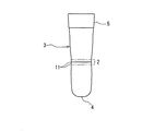
実施形態の靴下1には、図1(A)(B)に示すストッパー用バンド部2を設け、該ストッパー用バンド部2の位置を移動させることにより、図1(A)に示すふくらはぎの下端までのクルー丈のショートタイプと、図1(B)に示す膝下丈のロングタイプとに使い分けることができる構成としている。
なお、図1(A)(B)ではストッパー用バンド部2の位置を明確にするために斜線を付して図示しているが、靴下1の外観上においてストッパー用バンド部2は他の部位と同色として識別できないようにしている。
Hereinafter, embodiments of socks of the present invention will be described with reference to the drawings.
The
In FIGS. 1A and 1B, the position of the
靴下1は図2に示す構成で、平置状態で、つま先の先端P1から履き口側の他端P2までの長さ寸法L1は25〜35cmの範囲とし、本実施形態では29cmとしている。
また、平置き状態でつま先の先端P1から他端P2まで外観上は連続した直線状とし、ヒール部は形成していない。
The
Further, in a flat state, the appearance is a continuous straight line from the tip end P1 to the other end P2, and no heel portion is formed.
靴下1は、伸縮性糸からなる編糸を丸編機で編成してシームレスの筒状本体3を設け、該筒状本体3の一端開口を縫着して閉鎖したつま先先端部4を形成している。他端側の端末編組織はウエルト編み組織として履き口側バンド部5を形成し、その先端開口を履き口6としている。前記一端側のつま先先端部4からウエルト編み組織の履き口側バンド部5までは平編み組織としている。
The
前記つま先先端部4から平置き状態で土踏まずに相当する位置に前記ストッパー用バンド部2を足裏側から足甲側にかけた全周に渡って幅Wで形成している。該ストッパー用バンド部2の位置は、つま先より8〜18cmの距離L2をあけた位置に設け、幅Wは1〜5cmの範囲としている。本実施形態では、距離L2は12cmとし、幅Wは2cmとしている。
The
ストッパー用バンド部2は、長さ方向で隣接する領域7A、7Bより平編組織の編目のループを短くして緊締力を大としている。具体的には、平置き状態で、隣接領域7A、7Bの限界横伸び幅に対して62〜90%の伸び率としている。本実施形態では隣接領域7A、7Bに対して77%としている。
The
ストッパー用バンド部2に隣接する履き口側の隣接領域7Bは履き口側バンド部5に達するまで、段階的に編目のループを長くして緊締力を低下させるグラデーション編みとしている。即ち、図3に示すように、履き口側の隣接領域7Bでは、7B−1、7B−2、7B−3、7B−4と順次ループRを長くして限界横伸び幅を拡大し、履き口側バンド部5に隣接する領域7B−4では限界横伸び幅をストッパー用バンド部2の1.5〜2.2倍程度としている。本実施形態では領域7B−4の限界横伸び幅はストッパー用バンド部2の1.8倍としている。
一方、ストッパー用バンド部2のつま先側の隣接領域7Aは、図2に示すように、ストッパー用バンド部2に隣接する領域7A−1は前記領域7B−1と同組織とし、7A−2は7B−2と同組織としている。このように、ストッパー用バンド部2を挟む両側を同様な編組織とすることで、連続した外観を与えることができると共に、違和感がなく、フィット性において優れたものとしている。
なお、ストッパー用バンド部2のつま先側に隣接する前記領域7Aはつま先先端まで編み目のループを同じ長さとして同じ緊締力で編成し、領域7A全体を同組織としてもよい。また、つま先部分は1×1タックメッシュ編みとして強度をアップしてもよい。
The
On the other hand, as shown in FIG. 2, the
The
ウエルト編み組織とした履き口側バンド部5では、限界横伸び幅は前記隣接領域7B−4より小さく、履き口部分での緊締力を若干強めて履き口部分でのずり下がりを防止している。
In the mouth
靴下1を構成する編糸は、伸縮性を有する弾性糸であれば良い。
本実施形態では、ポリウレタン弾性芯糸にナイロンを巻き付けた51デジテックスのシングルカバーリングヤーンを用いている。
The knitting yarn constituting the
In this embodiment, a 51 digitex single covering yarn in which nylon is wrapped around a polyurethane elastic core yarn is used.
前記した1種類の編糸で全体を編成し、ストッパー用バンド部2は外観上において差異を設けておらず、ストッパー用バンド部2を設けていることが分からないようにしている。 なお、履き口側バンド部5となるウエルト編み組織の端末では、装飾用の編糸を挿入して編成してもよい。
The whole is knitted with the above-described one type of knitting yarn, and the
前記した緊締力を強めたストッパー用バンド部2を設けた靴下1では、該ストッパ用バンド部2の位置でずり下がりを阻止しているため、ストッパー用バンド部2の位置を図1(A)(B)に移動することにより、図1(A)に示すクルー丈のショートタイプと、図1(B)に示す膝下丈のロングタイプとに使い分けることできる。
In the
図1(A)に示すクルー丈とする場合は、ストッパー用バンド部2は踝を越えない位置、即ち、土踏まずの位置としている。この位置では隣接するつま先側と踝側よりも緊締力を大としているため、土踏まずから位置ずれせずに保持できる。
また、ストッパー用バンド部2の位置は、設計段階でつま先先端から土踏まずまでに相当する寸法をあけて設けているため、ストッパー用バンド部2からつま先先端部4までの領域7Aでダブりや弛みが発生することはない。
In the case of the crew length shown in FIG. 1 (A), the
In addition, since the
一方、図1(B)に示す膝下丈とする場合は、ストッパー用バンド部2を踝を越えて足首位置に移動させている。この場合、靴下を伸びの良い伸縮性編地から形成しているためストッパー用バンド部2からつま先先端部4までの領域7Aは着用者の足により無理なく伸ばされて足にフィットさせることができる。また、膝下に位置する履き口6の位置はストッパー用バンド部2が足首に位置するため膝下位置まで達することとなる。かつ、比較的緊締力を大とした履き口側バンド部5と併せ、伸びのよい伸縮性編地を用い、グラデーションにより伸びの変化を設設けている為、よくフィットし、膝下位置からずり下がるのを防止できる。
On the other hand, in the case of the below-knee length shown in FIG. 1B, the
なお、図4の変形例に示すように、ストッパー用バンド部2に色の相違する編糸を用いて表示ライン11を設けたり、同一糸で模様をいれた編み目として、ストッパー用バンド部2の位置が一目で視認できるようにしてもよい。
In addition, as shown in the modification of FIG. 4, the
1 靴下
2 ストッパー用バンド部
3 筒状本体
4 つま先側先端部
5 履き口側バンド部
6 履き口
R ループ
1 socks
2 Band part for
R loop
Claims (5)
前記筒状本体のつま先側先端部と履き口との間に、緊締力を大とした編地からなるストッパー用バンド部を周方向に連続して備え、該ストッパー用バンド部の位置を、土踏まずに位置させて着用すると前記履き口はふくらはぎの下端に位置するショートタイプとなり、前記バンド部の位置をかかとを越えて足首位置に位置させると履き口が膝下のロングタイプとなることを特徴とする靴下。 One end in the length direction of the tubular body made of elastic knitted fabric is sewn to the tip of the toe and the other end opening is a sock, and the heel is not formed,
Between the tip part on the toe side of the cylindrical main body and the mouth, a stopper band part made of a knitted fabric having a large tightening force is continuously provided in the circumferential direction, and the position of the stopper band part is The sock is a short type in which the mouth is located at the lower end of the calf when worn in a position, and the mouth is a long type under the knee when the band part is located at the ankle position beyond the heel. .
Priority Applications (1)
| Application Number | Priority Date | Filing Date | Title |
|---|---|---|---|
| JP2008143575A JP5216420B2 (en) | 2008-05-30 | 2008-05-30 | socks |
Applications Claiming Priority (1)
| Application Number | Priority Date | Filing Date | Title |
|---|---|---|---|
| JP2008143575A JP5216420B2 (en) | 2008-05-30 | 2008-05-30 | socks |
Publications (2)
| Publication Number | Publication Date |
|---|---|
| JP2009287151A true JP2009287151A (en) | 2009-12-10 |
| JP5216420B2 JP5216420B2 (en) | 2013-06-19 |
Family
ID=41456642
Family Applications (1)
| Application Number | Title | Priority Date | Filing Date |
|---|---|---|---|
| JP2008143575A Expired - Fee Related JP5216420B2 (en) | 2008-05-30 | 2008-05-30 | socks |
Country Status (1)
| Country | Link |
|---|---|
| JP (1) | JP5216420B2 (en) |
Citations (5)
| Publication number | Priority date | Publication date | Assignee | Title |
|---|---|---|---|---|
| JPS54135235U (en) * | 1978-03-09 | 1979-09-19 | ||
| JPS5943102A (en) * | 1982-08-31 | 1984-03-10 | 株式会社チエスコツト | Production of double socks |
| JPH1046404A (en) * | 1996-07-30 | 1998-02-17 | Tokyo Prod:Kk | Sports socks |
| JPH11217705A (en) * | 1998-01-30 | 1999-08-10 | Miyako Socks:Kk | Socks |
| JP2004197288A (en) * | 2002-12-16 | 2004-07-15 | Tetsuo Hasegawa | Double knitting sock and method for producing the same |
-
2008
- 2008-05-30 JP JP2008143575A patent/JP5216420B2/en not_active Expired - Fee Related
Patent Citations (5)
| Publication number | Priority date | Publication date | Assignee | Title |
|---|---|---|---|---|
| JPS54135235U (en) * | 1978-03-09 | 1979-09-19 | ||
| JPS5943102A (en) * | 1982-08-31 | 1984-03-10 | 株式会社チエスコツト | Production of double socks |
| JPH1046404A (en) * | 1996-07-30 | 1998-02-17 | Tokyo Prod:Kk | Sports socks |
| JPH11217705A (en) * | 1998-01-30 | 1999-08-10 | Miyako Socks:Kk | Socks |
| JP2004197288A (en) * | 2002-12-16 | 2004-07-15 | Tetsuo Hasegawa | Double knitting sock and method for producing the same |
Also Published As
| Publication number | Publication date |
|---|---|
| JP5216420B2 (en) | 2013-06-19 |
Similar Documents
| Publication | Publication Date | Title |
|---|---|---|
| JP6016360B2 (en) | Lower leg supporter | |
| US4149274A (en) | Anti-slip hosiery article and method | |
| JP5165122B2 (en) | Footwear | |
| JP6106865B2 (en) | Knitted fabric with varying pile length, knitted products and socks | |
| JP5031311B2 (en) | Footwear and socks | |
| KR20150121175A (en) | Method of knitting a knitted component with an integral knit tongue | |
| EP2157220B1 (en) | Knitting method for tubular knitted fabric and tubular knitted fabric | |
| US7775069B1 (en) | Therapeutic stocking | |
| US20060218973A1 (en) | Socks and method for knitting the same | |
| JP5411083B2 (en) | Leg wear | |
| JP2018048427A (en) | Knitted fabric and hosiery | |
| US6935141B2 (en) | Socks and method of manufacturing the socks | |
| KR20180038853A (en) | Tights | |
| JP6171130B2 (en) | socks | |
| US20210156058A1 (en) | Containing fabric, garments comprising such fabric, and related production methods | |
| JP5395567B2 (en) | Footwear | |
| JP5216420B2 (en) | socks | |
| JP2006348428A (en) | Knitting method of socks | |
| JP7373839B2 (en) | Tube knitted textile products | |
| JP2018059226A (en) | socks | |
| JP2023161495A (en) | Short sock | |
| JP2016204780A (en) | Sock | |
| JP3063340U (en) | Socks | |
| JP2023162684A (en) | Foot cover | |
| JP2019151937A (en) | Sock |
Legal Events
| Date | Code | Title | Description |
|---|---|---|---|
| A621 | Written request for application examination |
Free format text: JAPANESE INTERMEDIATE CODE: A621 Effective date: 20110404 |
|
| A977 | Report on retrieval |
Free format text: JAPANESE INTERMEDIATE CODE: A971007 Effective date: 20120725 |
|
| A131 | Notification of reasons for refusal |
Free format text: JAPANESE INTERMEDIATE CODE: A131 Effective date: 20120807 |
|
| A521 | Written amendment |
Free format text: JAPANESE INTERMEDIATE CODE: A523 Effective date: 20120914 |
|
| TRDD | Decision of grant or rejection written | ||
| A01 | Written decision to grant a patent or to grant a registration (utility model) |
Free format text: JAPANESE INTERMEDIATE CODE: A01 Effective date: 20130226 |
|
| A61 | First payment of annual fees (during grant procedure) |
Free format text: JAPANESE INTERMEDIATE CODE: A61 Effective date: 20130304 |
|
| R150 | Certificate of patent or registration of utility model |
Ref document number: 5216420 Country of ref document: JP Free format text: JAPANESE INTERMEDIATE CODE: R150 Free format text: JAPANESE INTERMEDIATE CODE: R150 |
|
| FPAY | Renewal fee payment (event date is renewal date of database) |
Free format text: PAYMENT UNTIL: 20160308 Year of fee payment: 3 |
|
| R250 | Receipt of annual fees |
Free format text: JAPANESE INTERMEDIATE CODE: R250 |
|
| R250 | Receipt of annual fees |
Free format text: JAPANESE INTERMEDIATE CODE: R250 |
|
| R250 | Receipt of annual fees |
Free format text: JAPANESE INTERMEDIATE CODE: R250 |
|
| R250 | Receipt of annual fees |
Free format text: JAPANESE INTERMEDIATE CODE: R250 |
|
| R250 | Receipt of annual fees |
Free format text: JAPANESE INTERMEDIATE CODE: R250 |
|
| LAPS | Cancellation because of no payment of annual fees |