JP2009286232A - Cassette gas cylinder attaching structure of utility machine - Google Patents

Cassette gas cylinder attaching structure of utility machine Download PDF

Info

Publication number
JP2009286232A
JP2009286232A JP2008140019A JP2008140019A JP2009286232A JP 2009286232 A JP2009286232 A JP 2009286232A JP 2008140019 A JP2008140019 A JP 2008140019A JP 2008140019 A JP2008140019 A JP 2008140019A JP 2009286232 A JP2009286232 A JP 2009286232A
Authority
JP
Japan
Prior art keywords
gas cylinder
cassette gas
case
cassette
flange
Prior art date
Legal status (The legal status is an assumption and is not a legal conclusion. Google has not performed a legal analysis and makes no representation as to the accuracy of the status listed.)
Granted
Application number
JP2008140019A
Other languages
Japanese (ja)
Other versions
JP4619423B2 (en
Inventor
Tomoki Ito
智樹 伊藤
Hideaki Kobayashi
秀明 小林
Masayuki Sasaoka
雅行 笹岡
Current Assignee (The listed assignees may be inaccurate. Google has not performed a legal analysis and makes no representation or warranty as to the accuracy of the list.)
Honda Motor Co Ltd
Original Assignee
Honda Motor Co Ltd
Priority date (The priority date is an assumption and is not a legal conclusion. Google has not performed a legal analysis and makes no representation as to the accuracy of the date listed.)
Filing date
Publication date
Application filed by Honda Motor Co Ltd filed Critical Honda Motor Co Ltd
Priority to JP2008140019A priority Critical patent/JP4619423B2/en
Priority to TW098117138A priority patent/TWI386550B/en
Priority to US12/471,001 priority patent/US8307803B2/en
Priority to EP09161185A priority patent/EP2128513B1/en
Priority to CN200910203579.0A priority patent/CN101590809B/en
Priority to KR1020090046658A priority patent/KR101049213B1/en
Priority to DE602009000332T priority patent/DE602009000332D1/en
Publication of JP2009286232A publication Critical patent/JP2009286232A/en
Application granted granted Critical
Publication of JP4619423B2 publication Critical patent/JP4619423B2/en
Active legal-status Critical Current
Anticipated expiration legal-status Critical

Links

Images

Classifications

    • Y02T10/32

Abstract

<P>PROBLEM TO BE SOLVED: To provide a cassette gas cylinder attaching structure of a utility machine capable of stably supporting a cassette gas cylinder against vibration of the utility machine. <P>SOLUTION: The cassette gas cylinder attaching structure 20 of the utility machine attaches the cassette gas cylinder 21 for supplying a fuel 24 to a gas engine 12 installed in the utility machine body 11. The cassette gas cylinder attaching structure 20 is equipped with a head support part 37 for supporting a head part 86 of the cassette gas cylinder 21 at the utility machine 10 side, and equipped with a flange receiving part 92 on which a flange 95 formed along an outer periphery of the head part 86 can abut at the head support part 37. <P>COPYRIGHT: (C)2010,JPO&INPIT

Description

本発明は、作業機本体に搭載されたエンジンに燃料を供給するカセットガスボンベを取り付ける作業機のカセットガスボンベ取付構造に関する。   The present invention relates to a cassette gas cylinder mounting structure for a work machine to which a cassette gas cylinder for supplying fuel to an engine mounted on a work machine body is attached.

作業機のなかには、作業機本体にガスエンジンが搭載され、作業機本体からハンドルポストが後上方へ向けて延出され、ハンドルポストにカセットガスボンベ取付構造が設けられ、カセットガスボンベ取付構造の収納ケース(以下、ガスボンベケースという)にカセットガスボンベが収納されたものがある(例えば、特許文献1参照。)。
特開平10−131809号公報
In the working machine, a gas engine is mounted on the working machine body, a handle post extends rearward and upward from the working machine body, a cassette gas cylinder mounting structure is provided on the handle post, and a cassette gas cylinder mounting structure storage case ( There is one in which a cassette gas cylinder is housed in a gas cylinder case (see, for example, Patent Document 1).
JP-A-10-131809

このカセットガスボンベ取付構造によれば、カセットガスボンベがガスボンベケースを介してハンドルポストに取り付けられている。
ハンドルポストにカセットガスボンベを取り付けることで、カセットガスボンベからガスエンジンに燃料ガスを供給してガスエンジンを駆動することが可能である。
According to this cassette gas cylinder mounting structure, the cassette gas cylinder is attached to the handle post via the gas cylinder case.
By attaching a cassette gas cylinder to the handle post, it is possible to supply fuel gas from the cassette gas cylinder to the gas engine and drive the gas engine.

ところで、カセットガスボンベは、容器の口金部中央に座部が設けられ、座部からノズルが突没自在に突出されている。
一方、ガスボンベケースは、座部に相当する部位にOリングが設けられている。
カセットガスボンベをガスボンベケースに収容した状態で、Oリングに座部が当接し、Oリングでノズル廻りのシール性を確保している。
By the way, the cassette gas cylinder is provided with a seat part in the center of the base part of the container, and the nozzle protrudes from the seat part so as to be able to project and retract.
On the other hand, the gas cylinder case is provided with an O-ring at a portion corresponding to the seat.
In a state where the cassette gas cylinder is accommodated in the gas cylinder case, the seat is in contact with the O-ring, and the sealing performance around the nozzle is secured by the O-ring.

しかし、ガスボンベケースを作業機に用いる場合、作業機で発生した振動でカセットガスボンベが座部を支点にして傾動する虞がある。
カセットガスボンベが傾動することで、Oリングに負担がかかり、耐久性を確保することが難しいことが考えられる。
However, when the gas cylinder case is used for the work machine, the cassette gas cylinder may be tilted with the seat portion as a fulcrum due to vibration generated by the work machine.
It is conceivable that the tilting of the cassette gas cylinder places a burden on the O-ring and it is difficult to ensure durability.

本発明は、作業機の振動に対してカセットガスボンベを安定的に支えることができる作業機のカセットガスボンベ取付構造を提供することを課題とする。   An object of the present invention is to provide a cassette gas cylinder mounting structure for a working machine that can stably support the cassette gas cylinder against vibrations of the working machine.

請求項1に係る発明は、作業機本体に搭載されたエンジンに燃料を供給するカセットガスボンベを取り付ける作業機のカセットガスボンベ取付構造において、作業機側に前記カセットガスボンベの口金部を支える口金支え部を備え、前記口金支え部に、前記口金部の外周に沿って形成されたフランジが当接可能なフランジ受部を備えたことを特徴とする。   The invention according to claim 1 is a cassette gas cylinder mounting structure for a working machine in which a cassette gas cylinder for supplying fuel to an engine mounted on the working machine body is attached. And a flange receiving portion with which a flange formed along an outer periphery of the base portion can be brought into contact with the base support portion.

請求項2は、前記カセットガスボンベを収容した状態で前記作業機側に取付け可能なガスボンベケースを備え、前記ガスボンベケースの先端部に、前記カセットガスボンベの前記フランジを外部に露出させる開口部を備え、前記ガスボンベケースの基端部側に、前記カセットガスボンベを前記開口部に向けて付勢する弾性部材を備えたことを特徴とする。   Claim 2 includes a gas cylinder case that can be attached to the working machine in a state in which the cassette gas cylinder is accommodated, and an opening that exposes the flange of the cassette gas cylinder to the outside at the tip of the gas cylinder case, An elastic member for urging the cassette gas cylinder toward the opening is provided on the base end side of the gas cylinder case.

請求項3は、前記作業機側に設けられて前記ガスボンベケースを保持可能な保持部材と、前記ガスボンベケースに設けられて前記保持部材が掛止め可能な掛止部と、を備え、前記掛止部に掛け止めした前記保持部材で前記ガスボンベケースを前記フランジ受部に向けて付勢することで、前記フランジを前記フランジ受部に当接させることを特徴とする。   According to a third aspect of the present invention, there is provided a holding member that is provided on the work machine side and can hold the gas cylinder case, and a hook portion that is provided on the gas cylinder case and can be hooked by the holding member. The flange is brought into contact with the flange receiving portion by urging the gas cylinder case toward the flange receiving portion with the holding member latched to the portion.

請求項4は、前記弾性部材としてコイルばね部材が用いられ、前記上半割ケースおよび前記下半割ケースのいずれか一方の基端部に、前記コイルばね部材の基端部を嵌合する嵌合溝部が設けられ、前記一方の基端部に、前記コイルばね部材の基端部を前記嵌合溝部に嵌合した状態に保持する保持突起が設けられたことを特徴とする。   According to a fourth aspect of the present invention, a coil spring member is used as the elastic member, and the base end portion of the coil spring member is fitted into one of the base end portions of the upper half case and the lower half case. A mating groove portion is provided, and a holding projection for holding the base end portion of the coil spring member in a state of being fitted in the fitting groove portion is provided on the one base end portion.

請求項1に係る発明では、作業機側に口金支え部を備え、口金支え部にフランジ受部を備えた。そして、カセットガスボンベの口金部に備えたフランジをフランジ受部に当接するようにした。
ここで、口金部のフランジは、口金部の外周に沿って形成された半径が比較的大きな鍔部である。
In the invention according to claim 1, the work support side is provided with the base support part, and the base support part is provided with the flange receiving part. And the flange with which the cap part of the cassette gas cylinder was equipped was made to contact | abut to a flange receiving part.
Here, the flange of the base part is a flange part having a relatively large radius formed along the outer periphery of the base part.

よって、カセットガスボンベのフランジをフランジ受部に当接することで、カセットガスボンベをフランジ受部で確実に支えることができる。
これにより、作業機の振動でカセットガスボンベが振れることを抑え、カセットガスボンベを安定的に支えることができる。
Therefore, the cassette gas cylinder can be reliably supported by the flange receiving portion by contacting the flange of the cassette gas cylinder with the flange receiving portion.
Thereby, it can suppress that a cassette gas cylinder shakes with the vibration of a working machine, and can support a cassette gas cylinder stably.

請求項2に係る発明では、ガスボンベケースの先端部にフランジを露出させる開口部を備えた。そして、開口部側に向けてカセットガスボンベを付勢する弾性部材を備えた。
カセットガスボンベを弾性部材で付勢することで、フランジを外部に露出させた状態を確実に保つことができる。
さらに、カセットガスボンベを弾性部材で付勢することで、作業機の振動でカセットガスボンベが振れることを抑え、カセットガスボンベを安定的に支えることができる。
In the invention which concerns on Claim 2, the opening part which exposes a flange was provided in the front-end | tip part of the gas cylinder case. And the elastic member which urges | biases a cassette gas cylinder toward the opening part side was provided.
By energizing the cassette gas cylinder with the elastic member, the state where the flange is exposed to the outside can be reliably maintained.
Furthermore, by energizing the cassette gas cylinder with the elastic member, the cassette gas cylinder can be prevented from being shaken by the vibration of the working machine, and the cassette gas cylinder can be stably supported.

請求項3に係る発明では、掛止部に保持部材を掛け止めすることで、保持部材でガスボンベケースをフランジ受部に向けて付勢することができる。
このように、ガスボンベケースをフランジ受部に向けて付勢することで、カセットガスボンベのフランジをフランジ受部に当接させることができる。
よって、カセットガスボンベをフランジ受部で確実に保持することができる。
これにより、ガスボンベケースに収容したカセットガスボンベを安定的に支えることができる。
In the invention which concerns on Claim 3, a gas cylinder case can be urged | biased toward a flange receiving part with a holding member by latching a holding member on a latching part.
Thus, by energizing the gas cylinder case toward the flange receiving portion, the flange of the cassette gas cylinder can be brought into contact with the flange receiving portion.
Therefore, the cassette gas cylinder can be reliably held by the flange receiving portion.
Thereby, the cassette gas cylinder accommodated in the gas cylinder case can be stably supported.

請求項4に係る発明では、弾性部材としてコイルばね部材を用い、上下の半割ケースの一方の基端部に嵌合溝部を設けるとともに保持突起を設けた。
嵌合溝部にコイルばね部材の基端部を嵌合し、嵌合溝部に嵌合した基端部を保持突起で保持するようにした。
これにより、ガスボンベケース内に弾性部材を簡単な構成で設けることができる。
In the invention according to claim 4, the coil spring member is used as the elastic member, and the fitting groove portion is provided at one base end portion of the upper and lower halved cases and the holding projection is provided.
The base end portion of the coil spring member is fitted into the fitting groove, and the base end fitted into the fitting groove is held by the holding projection.
Thereby, an elastic member can be provided in a gas cylinder case with a simple structure.

本発明を実施するための最良の形態を添付図に基づいて以下に説明する。なお、「前」、「後」、「左」、「右」は操作者から見た方向にしたがい、前側をFr、後側をRr、左側をL、右側をRとして示す。
ここで、本実施の形態では作業機のカセットガスボンベ取付構造として歩行型耕耘機を例示するが、作業機のカセットガスボンベ取付構造は歩行型耕耘機に限定するものではない。
The best mode for carrying out the present invention will be described below with reference to the accompanying drawings. Note that “front”, “rear”, “left”, and “right” indicate Fr as the front, Rr as the rear, L as the left, and R as the right according to the direction viewed from the operator.
Here, in this embodiment, a walking type tiller is exemplified as the cassette gas cylinder mounting structure of the working machine, but the cassette gas cylinder mounting structure of the working machine is not limited to the walking type tiller.

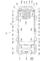
図1は本発明に係る作業機のカセットガスボンベ取付構造を示す側面図である。
作業機10は、作業機本体11の上端部に搭載されたガスエンジン(エンジン)12と、ガスエンジン12の下方に設けられた耕耘軸13と、耕耘軸13に設けられた複数の耕耘爪15と、作業機本体11に設けられた支持ブラケット16と、支持ブラケット16から後上方へ向けて延出されたハンドルコラム18と、ハンドルコラム18に設けられたカセットガスボンベ取付構造20と、カセットガスボンベ取付構造20に取り付けられたカセットガスボンベ21(図10参照)と、カセットガスボンベ取付構造20の周囲に設けられた運搬用のキャリーハンドル22と、ハンドルコラム18の上端部に設けられた操作ハンドル23とを備えている。
FIG. 1 is a side view showing a cassette gas cylinder mounting structure of a working machine according to the present invention.
The work machine 10 includes a gas engine (engine) 12 mounted on the upper end of the work machine main body 11, a tilling shaft 13 provided below the gas engine 12, and a plurality of tilling claws 15 provided on the tilling shaft 13. A support bracket 16 provided on the work machine main body 11, a handle column 18 extending rearward and upward from the support bracket 16, a cassette gas cylinder mounting structure 20 provided on the handle column 18, and a cassette gas cylinder installation A cassette gas cylinder 21 (see FIG. 10) attached to the structure 20, a carrying handle 22 for transportation provided around the cassette gas cylinder attachment structure 20, and an operation handle 23 provided at the upper end of the handle column 18 I have.

この作業機10は、ガスエンジン12の動力を耕耘軸13に伝達し、耕耘軸13を回転することにより、複数の耕耘爪15で土壌を耕耘しながら走行する歩行型耕耘機である。
ガスエンジン12は、カセットガスボンベ21から供給された液状の燃料ガス(以下、燃料という)24(図10参照)を供給することで駆動するエンジンである。
The work machine 10 is a walking type tiller that travels while cultivating soil with a plurality of tilling claws 15 by transmitting the power of the gas engine 12 to the tilling shaft 13 and rotating the tilling shaft 13.
The gas engine 12 is an engine that is driven by supplying a liquid fuel gas (hereinafter referred to as fuel) 24 (see FIG. 10) supplied from the cassette gas cylinder 21.

図2は本発明に係るカセットガスボンベ取付構造を示す斜視図、図3は本発明に係るカセットガスボンベ取付構造のレシーバからガスボンベケースを取り外した状態を示す斜視図である。
カセットガスボンベ取付構造20は、ハンドルコラム18に設けられたレシーバ(ケース搭載部)25と、レシーバ25に着脱可能に設けられたガスボンベケース26とを備えている。
FIG. 2 is a perspective view showing a cassette gas cylinder mounting structure according to the present invention, and FIG. 3 is a perspective view showing a state where a gas cylinder case is removed from the receiver of the cassette gas cylinder mounting structure according to the present invention.
The cassette gas cylinder mounting structure 20 includes a receiver (case mounting portion) 25 provided on the handle column 18 and a gas cylinder case 26 detachably provided on the receiver 25.

まず、レシーバ25を図2〜図8に基づいて説明する。
レシーバ25は、ハンドルコラム18に設けられたレシーバ本体31と、レシーバ本体31の先端部31aに設けられた取付ブラケット32と、レシーバ本体31の先端部31aに取付ブラケット32と共締めされた口金支え部/切替バルブ33と、取付ブラケット32に設けられたケース保持手段34と、ケース保持手段34に切替バルブ38を連動させるバルブ連動手段35とを備えている。
First, the receiver 25 will be described with reference to FIGS.
The receiver 25 includes a receiver main body 31 provided on the handle column 18, a mounting bracket 32 provided at the front end 31 a of the receiver main body 31, and a base support that is fastened together with the mounting bracket 32 on the front end 31 a of the receiver main body 31. Part / switching valve 33, case holding means 34 provided on the mounting bracket 32, and valve interlocking means 35 for interlocking the switching valve 38 with the case holding means 34.

このレシーバ25は、ケース保持手段34の保持ロッド(保持部材)41を保持位置P1(図2参照)に配置して掛止部42に掛け止めることで、レシーバ25にガスボンベケース26を保持することが可能である。
レシーバ25にガスボンベケース26を保持することで、カセットガスボンベ21が作業機10側に取り付けられた状態に保持される。
一方、保持ロッド41を掛止部42から外して開放位置P2(図3参照)に配置することで、レシーバ25からガスボンベケース26を外すことが可能である。
The receiver 25 holds the gas cylinder case 26 in the receiver 25 by placing the holding rod (holding member) 41 of the case holding means 34 at the holding position P1 (see FIG. 2) and hooking it on the hooking portion 42. Is possible.
By holding the gas cylinder case 26 in the receiver 25, the cassette gas cylinder 21 is held in a state of being attached to the work machine 10 side.
On the other hand, it is possible to remove the gas cylinder case 26 from the receiver 25 by removing the holding rod 41 from the latching portion 42 and disposing it at the open position P2 (see FIG. 3).

このように、ガスボンベケース26をレシーバ25に着脱自在に取り付けることで、ガスボンベケース26をレシーバ25から外すことができる。
よって、ガスボンベケース26にカセットガスボンベ21(図8参照)を収容した状態で持ち運ぶことができる。
Thus, the gas cylinder case 26 can be detached from the receiver 25 by detachably attaching the gas cylinder case 26 to the receiver 25.
Therefore, the cassette gas cylinder 21 (see FIG. 8) can be carried in the gas cylinder case 26.

これにより、カセットガスボンベ21を持ち運ぶ際に、ガスボンベケース26でカセットガスボンベ21を覆うことができる。
したがって、カセットガスボンベ21に衝撃や熱が加わったり、カセットガスボンベ21に塵埃などが付着することを防ぐことができる。
Thereby, when carrying the cassette gas cylinder 21, the cassette gas cylinder 21 can be covered with the gas cylinder case 26.
Therefore, it is possible to prevent impact or heat from being applied to the cassette gas cylinder 21 or dust from being attached to the cassette gas cylinder 21.

図4は本発明に係るレシーバのレシーバ本体を示す斜視図、図5は本発明に係るレシーバ本体を示す平面図、図6(a)は図5の6a−6a線断面図、図6(b)は図5の6b−6b線断面図である。
レシーバ25のレシーバ本体31は、平面視で略矩形状に形成された底部44と、底部44の先端部44aに設けられた左右の隆起部45,46と、左隆起部45から底部44の左側部に沿って後方に延ばされた左側壁47と、右隆起部46から底部44の右側部に沿って後方に延ばされた右側壁48と、底部44の基端部44bに設けられた装飾用カバー49と備えている。
4 is a perspective view showing a receiver body of the receiver according to the present invention, FIG. 5 is a plan view showing the receiver body according to the present invention, FIG. 6A is a sectional view taken along line 6a-6a in FIG. ) Is a cross-sectional view taken along line 6b-6b of FIG.
The receiver main body 31 of the receiver 25 includes a bottom portion 44 formed in a substantially rectangular shape in plan view, left and right raised portions 45, 46 provided at a distal end portion 44 a of the bottom portion 44, and the left raised portion 45 to the left side of the bottom portion 44. A left side wall 47 extending rearward along the right side, a right side wall 48 extending rearward along the right side of the bottom 44 from the right ridge 46, and a base end 44 b of the bottom 44. A decorative cover 49 is provided.

底部44は、先端部44aの幅方向中央に前取付孔51が形成されるとともに、基端部44bの幅方向中央に後取付孔52が形成されている。
また、底部44は、後半部に凹み部53が形成され、凹み部53の前側に第1凹部54が形成され、第1凹部54の前右端部に第2凹部55が形成され、第2凹部55の先端部55a(すなわち、右隆起部46の後側部)に排出用の異物排出口56が形成されている。
レシーバ本体31は前方に向けて下り勾配で配置されているので、第2凹部55の先端部55aは下部となる。
よって、異物排出口56は、底部44のうち最下部となる部位に設けられている。
The bottom portion 44 has a front mounting hole 51 formed in the center in the width direction of the distal end portion 44a and a rear mounting hole 52 formed in the center in the width direction of the base end portion 44b.
Further, the bottom portion 44 is formed with a recess 53 in the rear half, a first recess 54 is formed on the front side of the recess 53, a second recess 55 is formed on the front right end of the first recess 54, and a second recess A foreign matter discharge port 56 for discharge is formed at the front end portion 55a of 55 (that is, the rear side portion of the right raised portion 46).
Since the receiver main body 31 is disposed at a downward slope toward the front, the front end portion 55a of the second recess 55 is a lower portion.
Therefore, the foreign matter discharge port 56 is provided in a lowermost portion of the bottom portion 44.

このように、レシーバ本体31の底部44のうち最下部に異物排出口56を設けることで、レシーバ本体31の異物(砂、落葉など)を異物排出口56から容易に排出することができる。
これにより、レシーバ本体31の異物(砂、落葉など)を除去する保守(メンテナンス)の容易化を図ることができる。
Thus, by providing the foreign matter discharge port 56 at the lowermost part of the bottom 44 of the receiver main body 31, foreign matters (sand, fallen leaves, etc.) in the receiver main body 31 can be easily discharged from the foreign matter discharge port 56.
Thereby, the maintenance (maintenance) which removes the foreign material (sand, fallen leaves, etc.) of the receiver main body 31 can be facilitated.

さらに、レシーバ本体31からガスボンベケース26を取り外すことで、底部44を露出させることができる。
これにより、レシーバ本体31の底部44から異物(砂、落葉など)を一層除去しやすくなる。
Furthermore, the bottom 44 can be exposed by removing the gas cylinder case 26 from the receiver body 31.
This makes it easier to remove foreign matters (sand, fallen leaves, etc.) from the bottom 44 of the receiver main body 31.

前後の取付孔51,52にそれぞれボルト57(図6(a)参照)を差し込み、差し込んだボルト57をブラケット58を介してハンドルコラム18に取り付ける。
これにより、ハンドルコラム18にブラケット58を介してレシーバ本体31が固定されている(図6(a)参照)。
この状態で、ハンドルコラム18の上端部18aおよび操作ハンドル23の下端部23aが装飾用カバー49で覆われている(図2参照)。
Bolts 57 (see FIG. 6A) are respectively inserted into the front and rear mounting holes 51 and 52, and the inserted bolts 57 are attached to the handle column 18 via the brackets 58.
Thereby, the receiver main body 31 is fixed to the handle column 18 via the bracket 58 (see FIG. 6A).
In this state, the upper end portion 18a of the handle column 18 and the lower end portion 23a of the operation handle 23 are covered with a decorative cover 49 (see FIG. 2).

左右の隆起部45,46に、取付ブラケット32および口金支え部/切替バルブ33をボルト59(図3参照)で共締めするための取付孔45a,46aがそれぞれ形成されている。   Mounting holes 45a and 46a for fastening the mounting bracket 32 and the base support / switching valve 33 together with bolts 59 (see FIG. 3) are formed in the left and right raised portions 45 and 46, respectively.

右側壁48は、図6に示すように、後半部48aが、右外壁61、右内壁62、右頂部63で断面略コ字状に形成されている。
図4に示すように、右内壁62は、先端部62a寄りの部位に右案内溝64が形成され、右案内溝64の前側に右前スライダガイド部(スライダガイド部)65が形成され、右案内溝64の後方(すなわち、右内壁62の基端部)に右後スライダガイド部(スライダガイド部)66が形成されている。
右案内溝64は、傾斜面64aを有し、下部が底部44に連結されている。
As shown in FIG. 6, the right side wall 48 has a rear half portion 48 a formed of a right outer wall 61, a right inner wall 62, and a right top portion 63 in a substantially U-shaped cross section.
As shown in FIG. 4, the right inner wall 62 has a right guide groove 64 formed near the tip end portion 62 a, and a right front slider guide portion (slider guide portion) 65 formed on the front side of the right guide groove 64. A right rear slider guide portion (slider guide portion) 66 is formed behind the groove 64 (that is, the base end portion of the right inner wall 62).
The right guide groove 64 has an inclined surface 64 a and the lower part is connected to the bottom part 44.

図6(b)に示すように、右前スライダガイド部65は、底部44の右側部に設けられた下ガイド部位65aと、右内壁62の下端部に形成された上ガイド部位65bとを備えている。
下ガイド部位65aおよび上ガイド部位65bは所定間隔をおいて設けられている。
右前スライダガイド部65に右前スライダ部82が差し込まれた状態で、右前スライダ部82が底部44から離れる方向に浮くことを上ガイド部位65bで阻止する。
よって、右前スライダ部82が右前スライダガイド部65に保持した状態に保たれる。
As shown in FIG. 6B, the right front slider guide portion 65 includes a lower guide portion 65 a provided on the right side of the bottom portion 44 and an upper guide portion 65 b formed on the lower end portion of the right inner wall 62. Yes.
The lower guide portion 65a and the upper guide portion 65b are provided at a predetermined interval.
In the state where the right front slider portion 82 is inserted into the right front slider guide portion 65, the upper guide portion 65b prevents the right front slider portion 82 from floating in a direction away from the bottom portion 44.
Therefore, the right front slider portion 82 is held in the state held by the right front slider guide portion 65.

図6(a)に示すように、右後スライダガイド部66は、底部44の右側部に設けられた下ガイド部位66aと、右内壁62の下端部に形成された上ガイド部位66bとを備えている。
下ガイド部位66aおよび上ガイド部位66bは、右前スライダガイド部65と同様に所定間隔をおいて設けられている。
右後スライダガイド部66に右後スライダ部84が差し込まれた状態で、右後スライダ部84が底部44から離れる方向に浮くことを上ガイド部位66bで阻止する。
よって、右後スライダ部84が右後スライダガイド部66に保持した状態に保たれる。
As shown in FIG. 6A, the right rear slider guide portion 66 includes a lower guide portion 66 a provided on the right side of the bottom portion 44, and an upper guide portion 66 b formed on the lower end portion of the right inner wall 62. ing.
The lower guide portion 66a and the upper guide portion 66b are provided at a predetermined interval, like the right front slider guide portion 65.
In the state where the right rear slider portion 84 is inserted into the right rear slider guide portion 66, the upper guide portion 66b prevents the right rear slider portion 84 from floating away from the bottom portion 44.
Therefore, the right rear slider portion 84 is held in the state held by the right rear slider guide portion 66.

左側壁47は、右側壁48と左右対称の壁部である。
すなわち、左側壁47は、図6に示すように、後半部47a(図5参照)が、左外壁71、左内壁72、左頂部73で断面略コ字状に形成されている。
左内壁72は、先端部72a寄りの部位に左案内溝74が形成され、左案内溝74の前側に左前スライダガイド部(スライダガイド部)75が形成され、左案内溝74の後方(すなわち、左内壁72の基端部)に左後スライダガイド部(スライダガイド部)76が形成されている。
The left side wall 47 is a wall part symmetrical to the right side wall 48.
That is, as shown in FIG. 6, the rear wall 47 a (see FIG. 5) of the left side wall 47 is formed with a left outer wall 71, a left inner wall 72, and a left top 73 in a substantially U-shaped cross section.
The left inner wall 72 has a left guide groove 74 formed in a portion near the tip 72a, a left front slider guide portion (slider guide portion) 75 formed on the front side of the left guide groove 74, and a rear side of the left guide groove 74 (that is, A left rear slider guide portion (slider guide portion) 76 is formed on the base end portion of the left inner wall 72.

図6(b)に示すように、左前スライダガイド部75は、底部44の左側部に設けられた下ガイド部位75aと、左内壁72の下端部に形成された上ガイド部位75bとを備えている。
下ガイド部位75aおよび上ガイド部位75bは所定間隔をおいて設けられている。
左前スライダガイド部75に左前スライダ部81が差し込まれた状態で、左前スライダ部81が底部44から離れる方向に浮くことを上ガイド部位75bで阻止する。
よって、左前スライダ部81が左前スライダガイド部75に保持した状態に保たれる。
As shown in FIG. 6B, the left front slider guide portion 75 includes a lower guide portion 75 a provided on the left side of the bottom portion 44 and an upper guide portion 75 b formed on the lower end portion of the left inner wall 72. Yes.
The lower guide portion 75a and the upper guide portion 75b are provided at a predetermined interval.
In the state where the left front slider portion 81 is inserted into the left front slider guide portion 75, the upper guide portion 75 b prevents the left front slider portion 81 from floating away from the bottom portion 44.
Therefore, the left front slider portion 81 is maintained in the state held by the left front slider guide portion 75.

図6(a)に示すように、左後スライダガイド部76は、底部44の左側部に設けられた下ガイド部位76aと、左内壁72の下端部に形成された上ガイド部位76bとを備えている。
下ガイド部位76aおよび上ガイド部位76bは、左前スライダガイド部75と同様に所定間隔をおいて設けられている。
左後スライダガイド部76に左後スライダ部83が差し込まれた状態で、左後スライダ部83が底部44から離れる方向に浮くことを上ガイド部位76bで阻止する。
よって、左後スライダ部83が左後スライダガイド部76に保持した状態に保たれる。
As shown in FIG. 6A, the left rear slider guide portion 76 includes a lower guide portion 76 a provided on the left side of the bottom portion 44 and an upper guide portion 76 b formed on the lower end portion of the left inner wall 72. ing.
The lower guide portion 76 a and the upper guide portion 76 b are provided at a predetermined interval, like the left front slider guide portion 75.
In the state where the left rear slider portion 83 is inserted into the left rear slider guide portion 76, the upper guide portion 76b prevents the left rear slider portion 83 from floating away from the bottom portion 44.
Therefore, the left rear slider portion 83 is maintained in the state held by the left rear slider guide portion 76.

左右の前スライダガイド部75,65は、ガスボンベケース26の左右の前スライダ部81,82(図13参照)を口金支え部37(図3参照)に向けて摺動自在に支持可能な部位である。
左右の後スライダガイド部76,66は、ガスボンベケース26の左右の後スライダ部83,84(図13参照)を口金支え部37(図3参照)に向けて摺動自在に支持可能な部位である。
The left and right front slider guide portions 75 and 65 are portions that can slidably support the left and right front slider portions 81 and 82 (see FIG. 13) of the gas cylinder case 26 toward the base support portion 37 (see FIG. 3). is there.
The left and right rear slider guide portions 76, 66 are portions that can slidably support the left and right rear slider portions 83, 84 (see FIG. 13) of the gas cylinder case 26 toward the base support portion 37 (see FIG. 3). is there.

このように、レシーバ25のレシーバ本体31に左右の前スライダガイド部75,65および左右の後スライダガイド部76,66を設け、ガスボンベケース26に左右の前スライダ部81,82および左右の後スライダ部83,84を設けた。
そして、左右の前スライダガイド部75,65で左右の前スライダ部81,82を支持し、左右の後スライダガイド部76,66で左右の後スライダ部83,84を支持するようにした。
As described above, the receiver main body 31 of the receiver 25 is provided with the left and right front slider guide portions 75 and 65 and the left and right rear slider guide portions 76 and 66, and the gas cylinder case 26 has the left and right front slider portions 81 and 82 and the left and right rear sliders. Portions 83 and 84 were provided.
The left and right front slider guide portions 75 and 65 support the left and right front slider portions 81 and 82, and the left and right rear slider guide portions 76 and 66 support the left and right rear slider portions 83 and 84.

よって、左右の前スライダ部81,82および左右の後スライダ部83,84をレシーバ本体31から浮き上がらせることなく、口金支え部37(図3参照)に向けて摺動させることができる。
これにより、左右の前スライダ部81,82および左右の後スライダ部83,84を摺動させるだけの簡単な操作手順で、ガスボンベケース26(カセットガスボンベ21)を所定の取付位置に取り付けることができる(位置決めすることができる)。
これにより、ガスボンベケース26の取付け(位置決め)が容易になる。
Therefore, the left and right front slider portions 81 and 82 and the left and right rear slider portions 83 and 84 can be slid toward the base support portion 37 (see FIG. 3) without being lifted from the receiver body 31.
Thereby, the gas cylinder case 26 (cassette gas cylinder 21) can be attached to a predetermined attachment position by a simple operation procedure in which the left and right front slider portions 81 and 82 and the left and right rear slider portions 83 and 84 are slid. (Can be positioned).
Thereby, attachment (positioning) of the gas cylinder case 26 is facilitated.

さらに、左右の前スライダガイド部75,65や左右の後スライダガイド部76,66に左右の前スライダ部81,82や左右の後スライダ部83,84を差し込むことで、ガスボンベケース26を強固に固定することができる。
これにより、ガスボンベケース26の耐振性を高めることができる。
なお、ガスボンベケース26をレシーバ本体31に着脱自在に取り付ける手順については図17〜図18で詳しく説明する。
Further, by inserting the left and right front slider portions 81 and 82 and the left and right rear slider portions 83 and 84 into the left and right front slider guide portions 75 and 65 and the left and right rear slider guide portions 76 and 66, the gas cylinder case 26 is strengthened. Can be fixed.
Thereby, the vibration resistance of the gas cylinder case 26 can be improved.
A procedure for detachably attaching the gas cylinder case 26 to the receiver body 31 will be described in detail with reference to FIGS.

図7は本発明に係るレシーバの口金支え部および切替バルブを示す斜視図、図8は本発明に係るレシーバの口金支え部でカセットガスボンベの口金部を支えた状態を示す断面図である。
レシーバ25の口金支え部/切替バルブ33は、口金支え部37および切替バルブ38が一体に形成された部材であり、左右の隆起部45,46に一対のボルト59(1個のみを図示する)で取り付けられている。
FIG. 7 is a perspective view showing a base support portion and a switching valve of a receiver according to the present invention, and FIG. 8 is a cross-sectional view showing a state where the base portion of the cassette gas cylinder is supported by the base support portion of the receiver according to the present invention.
The base support / switching valve 33 of the receiver 25 is a member in which the base support 37 and the switching valve 38 are integrally formed, and a pair of bolts 59 (only one is shown) on the left and right raised portions 45 and 46. It is attached with.

口金支え部37は、カセットガスボンベ21の口金部86を支える部位である。
この口金支え部37は、カセットガスボンベ21のノズル87を受け入れるノズル収容凹部88を同軸上に備え、ノズル収容凹部88内にカセットガスボンベ21の座部90に当接するOリング91を備え、ノズル収容凹部88と同軸上にフランジ受部92を備えている。
The base support part 37 is a part that supports the base part 86 of the cassette gas cylinder 21.
The base support portion 37 includes a nozzle housing recess 88 that receives the nozzle 87 of the cassette gas cylinder 21 on the same axis, and includes an O-ring 91 that contacts the seat 90 of the cassette gas cylinder 21 in the nozzle housing recess 88. A flange receiving portion 92 is provided coaxially with 88.

カセットガスボンベ21を収容したガスボンベケース26をレシーバ25に取り付けることで、カセットガスボンベ21の座部90がOリング91に当接する。
座部90がOリング91に当接することで、ノズル87廻りのシール性がOリング91で確保される。
By attaching the gas cylinder case 26 containing the cassette gas cylinder 21 to the receiver 25, the seat 90 of the cassette gas cylinder 21 contacts the O-ring 91.
When the seat 90 abuts on the O-ring 91, the O-ring 91 ensures sealing performance around the nozzle 87.

フランジ受部92は、口金支え部37の外周壁37aに沿って形成された環状の受部である。
フランジ受部92を外周壁37aに沿って形成することで、フランジ受部92の半径Rが比較的大きく確保されている。
The flange receiving portion 92 is an annular receiving portion formed along the outer peripheral wall 37 a of the base support portion 37.
By forming the flange receiving part 92 along the outer peripheral wall 37a, the radius R of the flange receiving part 92 is ensured comparatively large.

このフランジ受部92は、カセットガスボンベ21を口金支え部37にセットした際に、カセットガスボンベ21のフランジ95を当接可能な部位である。
フランジ95は、口金部86の外周に沿って形成された半径が比較的大きな鍔部である。
カセットガスボンベ21のフランジ95を、半径Rが比較的大きなフランジ受部92に当接することで、カセットガスボンベ21をフランジ受部92で確実に支えることができる。
The flange receiving portion 92 is a portion that can contact the flange 95 of the cassette gas cylinder 21 when the cassette gas cylinder 21 is set on the base support portion 37.
The flange 95 is a flange having a relatively large radius formed along the outer periphery of the base portion 86.
By contacting the flange 95 of the cassette gas cylinder 21 with a flange receiving portion 92 having a relatively large radius R, the cassette gas cylinder 21 can be reliably supported by the flange receiving portion 92.

切替バルブ38は、口金支え部37に一体に形成されたコック本体97と、コック本体97内に弁体(図示せず)が設けられ、この弁体に操作レバー98が設けられている。
操作レバー98を燃料供給位置P3(図2参照)に配置することで、コック本体97内の流路を開くように弁体が配置される。
よって、切替バルブ38は、図1に示すガスエンジン12に燃料24(図10参照)を供給する燃料供給状態に保持される。
The switching valve 38 includes a cock main body 97 formed integrally with the base support portion 37, and a valve body (not shown) provided in the cock main body 97, and an operation lever 98 is provided on the valve body.
By disposing the operation lever 98 at the fuel supply position P3 (see FIG. 2), the valve body is disposed so as to open the flow path in the cock body 97.
Therefore, the switching valve 38 is maintained in a fuel supply state in which the fuel 24 (see FIG. 10) is supplied to the gas engine 12 shown in FIG.

一方、操作レバー98を燃料遮断位置P4(図3参照)に配置することで、コック本体97内の流路を閉じるように弁体が配置される。
よって、切替バルブ38は、ガスエンジン12への燃料24の供給を停止する燃料遮断状態に保持される。
On the other hand, by disposing the operation lever 98 at the fuel cutoff position P4 (see FIG. 3), the valve body is disposed so as to close the flow path in the cock body 97.
Therefore, the switching valve 38 is maintained in a fuel cutoff state in which the supply of the fuel 24 to the gas engine 12 is stopped.

なお、レシーバ25は、口金支え部37を塞ぐシャッタ部材99を備えている。シャッタ部材99は、レシーバ25からカセットガスボンベ21を取り外した際に、ばね部材101の付勢力で口金支え部37を塞ぐ部材である。   The receiver 25 includes a shutter member 99 that closes the base support portion 37. The shutter member 99 is a member that closes the base support portion 37 with the urging force of the spring member 101 when the cassette gas cylinder 21 is removed from the receiver 25.

図2、図3に戻って、レシーバ25のケース保持手段34は、取付ブラケット32に回動自在に設けられた保持ロッド(保持部材)41と、保持ロッド41に設けられた口金カバー部104と、保持ロッド41を保持位置P1に保持するロックばね部材105とを備えている。   2 and 3, the case holding means 34 of the receiver 25 includes a holding rod (holding member) 41 that is rotatably provided on the mounting bracket 32, and a base cover portion 104 that is provided on the holding rod 41. And a lock spring member 105 for holding the holding rod 41 at the holding position P1.

保持ロッド41は、左右の脚部106,107の基端部がそれぞれ取付ブラケット32に回動自在に支持され、左右の脚部106,107の先端部106a,107aから左右のフック部108,109がそれぞれ延出され、左右のフック部108,109の先端部108a,109aがグリップ部111でそれぞれ連結されている。   In the holding rod 41, the base end portions of the left and right leg portions 106, 107 are rotatably supported by the mounting bracket 32, respectively, and the left and right hook portions 108, 109 from the distal end portions 106a, 107a of the left and right leg portions 106, 107. Are extended, and the front end portions 108a and 109a of the left and right hook portions 108 and 109 are connected by the grip portion 111, respectively.

口金カバー部104は、左右の脚部106,107のそれぞれの基端部に渡って設けられ、カセットガスボンベ21の口金部86や口金部86の近傍を覆う部材である。
ロックばね部材105は、右脚部107の基端部および取付ブラケット32に係止され、保持ロッド41を保持位置P1に保持するコイルばねである。
The base cover portion 104 is a member that is provided over the base ends of the left and right leg portions 106 and 107 and covers the base portion 86 of the cassette gas cylinder 21 and the vicinity of the base portion 86.
The lock spring member 105 is a coil spring that is locked to the proximal end portion of the right leg 107 and the mounting bracket 32 and holds the holding rod 41 at the holding position P1.

左右の脚部106,107は、ガスボンベケース26の外側に位置している。
左右のフック部108,109は、ガスボンベケース26の外側から中央に向けて延出されている。
左右のフック部108,109を中央に向けて延出することで、左右のフック部108,109をガスボンベケース26の掛止部42に掛け止めすることができる。
The left and right leg portions 106 and 107 are located outside the gas cylinder case 26.
The left and right hook portions 108 and 109 extend from the outside of the gas cylinder case 26 toward the center.
By extending the left and right hook portions 108 and 109 toward the center, the left and right hook portions 108 and 109 can be hooked on the hook portion 42 of the gas cylinder case 26.

左右のフック部108,109をガスボンベケース26の掛止部42に掛け止めすることで、ガスボンベケース26が後方に移動しないように保持することができる。
すなわち、図13に示す左右の前スライダ部81,82を左右の前スライダガイド部75,65(図6参照)に保持し、かつ、図13に示す左右の後スライダ部83,84を左右の後スライダガイド部76,66(図6参照)に保持した状態に保つことができる。
これにより、レシーバ25にガスボンベケース26を取り付けた状態に保持することができる。
By hooking the left and right hook portions 108 and 109 to the hook portion 42 of the gas cylinder case 26, the gas cylinder case 26 can be held so as not to move backward.
That is, the left and right front slider portions 81 and 82 shown in FIG. 13 are held by the left and right front slider guide portions 75 and 65 (see FIG. 6), and the left and right rear slider portions 83 and 84 shown in FIG. The rear slider guide portions 76 and 66 (see FIG. 6) can be held.
Thereby, it can hold | maintain in the state which attached the gas cylinder case 26 to the receiver 25. FIG.

さらに、保持ロッド41を掛止部42に掛け止めすることで、ガスボンベケース26を保持ロッド41で口金支え部37のフランジ受部92(図7も参照)に向けて付勢することができる。
このように、ガスボンベケース26をフランジ受部92に向けて付勢することで、カセットガスボンベ21のフランジ95をフランジ受部92に当接させることができる。
Furthermore, by holding the holding rod 41 on the hook portion 42, the gas cylinder case 26 can be biased toward the flange receiving portion 92 (see also FIG. 7) of the base support portion 37 with the holding rod 41.
Thus, by urging the gas cylinder case 26 toward the flange receiving portion 92, the flange 95 of the cassette gas cylinder 21 can be brought into contact with the flange receiving portion 92.

よって、カセットガスボンベ21をフランジ受部92で確実に保持することができる。
これにより、ガスボンベケース26に収容したカセットガスボンベ21を安定的に支えることができる。
Therefore, the cassette gas cylinder 21 can be reliably held by the flange receiving portion 92.
Thereby, the cassette gas cylinder 21 accommodated in the gas cylinder case 26 can be stably supported.

この状態において、図8に示すように、カセットガスボンベ21の座部90がOリング91に好適に当接する。
座部90がOリング91に好適に当接することで、ノズル87廻りのシール性がOリング91で確保される。
In this state, as shown in FIG. 8, the seat portion 90 of the cassette gas cylinder 21 is preferably in contact with the O-ring 91.
Since the seat portion 90 is preferably in contact with the O-ring 91, the sealing performance around the nozzle 87 is ensured by the O-ring 91.

さらに、保持ロッド41を掛止部42に掛け止めした状態で、ガスボンベケース26の先端部26aは、図8に示すように、口金支え部37に当接していない。
よって、ガスボンベケース26の先端部26aが口金支え部37で拘束されない状態(いわゆる、フリーの状態)に保たれる。
Further, the tip end portion 26a of the gas cylinder case 26 is not in contact with the base support portion 37 as shown in FIG.
Therefore, the front end portion 26 a of the gas cylinder case 26 is kept in a state where it is not restrained by the base support portion 37 (so-called free state).

これにより、カセットガスボンベ21のフランジ95がフランジ受部92に当接するまでガスボンベケース26を移動させることができる。
したがって、カセットガスボンベ21のフランジ95をフランジ受部92に確実に当接させることができる。
なお、ガスボンベケース26の掛止部42については後で詳しく説明する。
Thereby, the gas cylinder case 26 can be moved until the flange 95 of the cassette gas cylinder 21 contacts the flange receiving portion 92.
Therefore, the flange 95 of the cassette gas cylinder 21 can be reliably brought into contact with the flange receiving portion 92.
The latch 42 of the gas cylinder case 26 will be described in detail later.

グリップ部111は、操作者の手で把持可能に形成されている。
グリップ部111を手で把持してロックばね部材105の付勢力に抗して保持ロッド41を保持位置P1から開放位置P2まで引き上げることができる。
The grip part 111 is formed so that it can be gripped by the operator's hand.
The grip portion 111 can be grasped by hand and the holding rod 41 can be lifted from the holding position P1 to the open position P2 against the urging force of the lock spring member 105.

レシーバ25のバルブ連動手段35は、操作レバー98から突出された従動突部114と、口金カバー部104の左側辺104aに設けられた駆動突片(駆動突部)116とを備えている。
従動突部114は、操作レバー98の上端部98aから上方に向けて延びた略L字状の部位117と、この部位117の先端部117a(図7参照)から保持ロッド41に向けて張り出された従動係止片118(図7も参照)とを備えている。
The valve interlocking means 35 of the receiver 25 includes a driven protrusion 114 protruding from the operation lever 98 and a driving protrusion (driving protrusion) 116 provided on the left side 104 a of the base cover portion 104.
The driven projection 114 extends substantially upward from the upper end 98a of the operation lever 98 and extends substantially toward the holding rod 41 from the tip 117a (see FIG. 7) of the portion 117. And a driven locking piece 118 (see also FIG. 7).

駆動突片116は、口金カバー部104の左側辺から外側(操作レバー98側)に向けて張り出された張出片121と、張出片121から左脚部106に沿って従動係止片118まで延びた駆動係止片122とを備えている。
張出片121や駆動係止片122は、操作レバー98の従動係止片118に当接可能に形成されている。
The drive protrusions 116 are extended from the left side of the base cover 104 toward the outside (the operation lever 98 side), and the driven locking pieces are extended from the extension 121 to the left leg 106. And a driving locking piece 122 extending to 118.
The overhanging piece 121 and the driving locking piece 122 are formed so as to be able to contact the driven locking piece 118 of the operation lever 98.

バルブ連動手段35によれば、図2に示すように、カセットガスボンベ21を保持ロッド41で保持した状態において、操作レバー98を燃料供給位置P3に切り替えたとき従動係止片118が駆動係止片122に当接する。
この状態からカセットガスボンベ21の保持を解除する開放位置P2の方向に保持ロッド41を移動するとき、駆動突片116(駆動係止片122や張出片121)で従動係止片118を移動させて、操作レバー98を燃料遮断位置P4まで連動させることができる。
According to the valve interlocking means 35, when the operation lever 98 is switched to the fuel supply position P3 in the state where the cassette gas cylinder 21 is held by the holding rod 41 as shown in FIG. 122 abuts.
From this state, when the holding rod 41 is moved in the direction of the open position P2 where the holding of the cassette gas cylinder 21 is released, the driven locking piece 118 is moved by the driving protrusion 116 (the driving locking piece 122 or the overhanging piece 121). Thus, the operation lever 98 can be interlocked to the fuel cutoff position P4.

すなわち、ケース保持手段34によるカセットガスボンベ21の保持を解除する際に、保持ロッド41の移動に連動させて切替バルブ38を燃料供給状態から燃料遮断状態に切り替えることができる。
よって、ガスボンベケース26をレシーバ本体31から取り外す際に、切替バルブ38を個別に操作して燃料遮断状態に切り替える必要がないので、ガスボンベケース26を簡単な操作手順で取り外すことができる。
That is, when releasing the holding of the cassette gas cylinder 21 by the case holding means 34, the switching valve 38 can be switched from the fuel supply state to the fuel cutoff state in conjunction with the movement of the holding rod 41.
Therefore, when removing the gas cylinder case 26 from the receiver main body 31, there is no need to individually operate the switching valve 38 to switch to the fuel cutoff state, so that the gas cylinder case 26 can be removed with a simple operation procedure.

一方、ガスエンジン12を始動する際には、操作レバー98を燃料遮断位置P4から燃料供給位置P3まで操作者が操作して切替バルブ38を燃料供給状態に切り替える。
これにより、ガスエンジン12の始動時の作業者への意識高揚を図ることができる。
On the other hand, when the gas engine 12 is started, the operator operates the operation lever 98 from the fuel cutoff position P4 to the fuel supply position P3 to switch the switching valve 38 to the fuel supply state.
As a result, it is possible to raise the awareness of the operator when starting the gas engine 12.

つぎに、ガスボンベケース26を図9〜図16に基づいて説明する。
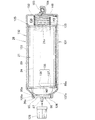
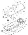
図9は本発明に係るカセットガスボンベ取付構造のガスボンベケースを示す斜視図、図10は本発明に係るガスボンベケースを示す断面図、図11は本発明に係るガスボンベケースを示す分解斜視図である。
ガスボンベケース26は、内部空間125にカセットガスボンベ21を収容した状態で、レシーバ25に着脱自在に取り付けることができるケースである。
ガスボンベケース26は、先端部26aに開口部126を備えている。開口部126は、カセットガスボンベ21の口金部86を外部に露出させる開口である。
Next, the gas cylinder case 26 will be described with reference to FIGS.
9 is a perspective view showing a gas cylinder case of the cassette gas cylinder mounting structure according to the present invention, FIG. 10 is a sectional view showing the gas cylinder case according to the present invention, and FIG. 11 is an exploded perspective view showing the gas cylinder case according to the present invention.
The gas cylinder case 26 is a case that can be detachably attached to the receiver 25 in a state where the cassette gas cylinder 21 is accommodated in the internal space 125.
The gas cylinder case 26 includes an opening 126 at the tip end portion 26a. The opening 126 is an opening that exposes the base 86 of the cassette gas cylinder 21 to the outside.

口金部86を開口部126から外部に露出させることで、図10に示すように、カセットガスボンベ21をガスボンベケース26内に収容した状態で、カセットガスボンベ21のキャップ128を着脱することができる。
このように、カセットガスボンベ21をガスボンベケース26内に収容した状態で、カセットガスボンベ21にキャップ128を着脱できるので使い勝手を高めることができる。
By exposing the base 86 to the outside through the opening 126, the cap 128 of the cassette gas cylinder 21 can be attached and detached while the cassette gas cylinder 21 is housed in the gas cylinder case 26 as shown in FIG.
As described above, the cap 128 can be attached to and detached from the cassette gas cylinder 21 in a state where the cassette gas cylinder 21 is accommodated in the gas cylinder case 26, so that the usability can be improved.

このガスボンベケース26は、レシーバ本体31に着脱可能に設けられる下半割ケース131と、下半割ケース131に組み付けられる上半割ケース132との2つの半割体で構成されている。
下半割ケース131にはコイルばね部材(弾性部材)133が設けられている。
コイルばね部材133は、カセットガスボンベ21を開口部126側に向けて付勢するばねである。
The gas cylinder case 26 is composed of two halves, a lower half case 131 detachably provided on the receiver body 31 and an upper half case 132 assembled to the lower half case 131.
The lower half case 131 is provided with a coil spring member (elastic member) 133.
The coil spring member 133 is a spring that biases the cassette gas cylinder 21 toward the opening 126 side.

下半割ケース131は、下前周壁部144および下後周壁部145がそれぞれ断面略半円弧状に形成されるとともに、下中央周壁部146が断面略コ字状に形成されている。
下中央周壁部146は、左右の側壁部位161,162および底部163(図15参照)で断面略コ字状に形成されている。
下前周壁部144の先端部144aに下前壁部147が設けられている。また、下後周壁部145の基端部145aに下後壁部148が設けられている。
In the lower half case 131, a lower front peripheral wall portion 144 and a lower rear peripheral wall portion 145 are each formed in a substantially semicircular cross section, and a lower central peripheral wall portion 146 is formed in a substantially U-shaped cross section.
The lower central peripheral wall portion 146 is formed in a substantially U-shaped cross section at left and right side wall portions 161 and 162 and a bottom portion 163 (see FIG. 15).
A lower front wall portion 147 is provided at the tip end portion 144 a of the lower front peripheral wall portion 144. Further, a lower rear wall portion 148 is provided at the base end portion 145 a of the lower rear peripheral wall portion 145.

下前周壁部144、下後周壁部145、下中央周壁部146、下前壁部147および下後壁部148で上方が開口した下部空間149が形成されている。
下部空間149は、カセットガスボンベ21の下半部を収容する空間である。
A lower space 149 having an upper opening is formed by the lower front peripheral wall portion 144, the lower rear peripheral wall portion 145, the lower central peripheral wall portion 146, the lower front wall portion 147, and the lower rear wall portion 148.
The lower space 149 is a space that accommodates the lower half of the cassette gas cylinder 21.

上半割ケース132は、上周壁部151が断面略半円弧状に形成され、上周壁部151の先端部151aに上前壁部152が設けられ、上周壁部151の基端部151bに上後壁部153が設けられている。
上周壁部151、上前壁部152および上後壁部153で下方が開口した上部空間154が形成されている。
上部空間154は、カセットガスボンベ21の上半部を収容する空間である。
The upper half case 132 has an upper peripheral wall portion 151 having a substantially semicircular cross section, an upper front wall portion 152 provided at a distal end portion 151 a of the upper peripheral wall portion 151, and an upper rear wall portion at a base end portion 151 b of the upper peripheral wall portion 151. 153 is provided.
An upper space 154 is formed in the upper peripheral wall portion 151, the upper front wall portion 152, and the upper rear wall portion 153.
The upper space 154 is a space that accommodates the upper half of the cassette gas cylinder 21.

上半割ケース132を下半割ケース131に組み付けることでガスボンベケース26が形成される。
よって、下部空間149および上部空間154でガスボンベケース26の内部空間125が形成される。
The gas cylinder case 26 is formed by assembling the upper half case 132 to the lower half case 131.
Therefore, the inner space 125 of the gas cylinder case 26 is formed by the lower space 149 and the upper space 154.

上半割ケース132および下半割ケース131からなるガスボンベケース26の内部(内部空間125)にカセットガスボンベ21が収容されている。
この状態で、カセットガスボンベ21に備えたフランジ95の外周部95c(図8も参照)が、下半割ケース131および上半割ケース132で上下方向から挟み込まれている。
The cassette gas cylinder 21 is accommodated in the gas cylinder case 26 (internal space 125) including the upper half case 132 and the lower half case 131.
In this state, the outer peripheral portion 95c (see also FIG. 8) of the flange 95 provided in the cassette gas cylinder 21 is sandwiched between the lower half case 131 and the upper half case 132 from the vertical direction.

カセットガスボンベ21は、容器89内に、ブタンを主成分とする液化ブタン(液状の燃料ガス)24を充填した市販のガスボンベである。
このカセットガスボンベ21は、容器89の先端部に口金部86を備え、口金部86の中央からノズル87が突出され、容器89内に略L字形の導入管135が設けられている。
The cassette gas cylinder 21 is a commercially available gas cylinder in which a container 89 is filled with liquefied butane (liquid fuel gas) 24 mainly containing butane.
The cassette gas cylinder 21 includes a base part 86 at the tip of a container 89, a nozzle 87 projects from the center of the base part 86, and a substantially L-shaped introduction pipe 135 is provided in the container 89.

ノズル87を容器89側に押し込むことで、容器89内に蓄えられた液状の燃料24を導入管135からノズル87まで導き、ノズル87から外部に導き出すことができる。
導入管135は、ノズル87と同軸上に延びる第1導入管部136と、第1導入管部136の端部から略直交する方向に下向きに延びた第2導入管部137とで略L字状に形成されている。
第2導入管部137を下向きに延ばすことで、第2導入管部137の導入口137aは容器89の前下部周壁89a近傍に配置されている。
By pushing the nozzle 87 toward the container 89, the liquid fuel 24 stored in the container 89 can be guided from the introduction pipe 135 to the nozzle 87 and led out from the nozzle 87.
The introduction pipe 135 is substantially L-shaped with a first introduction pipe part 136 extending coaxially with the nozzle 87 and a second introduction pipe part 137 extending downward in a direction substantially orthogonal to the end of the first introduction pipe part 136. It is formed in a shape.
By extending the second introduction pipe part 137 downward, the introduction port 137 a of the second introduction pipe part 137 is disposed in the vicinity of the front lower peripheral wall 89 a of the container 89.

ここで、口金部86の外周86aにフランジ95が形成され、フランジ95に切欠141が形成されている。
切欠141は、位置決め突部142に係合可能に形成されている。位置決め突部142は、ガスボンベケース26の内部(具体的には、開口部126近傍の内部)に形成されている。
Here, a flange 95 is formed on the outer periphery 86 a of the base portion 86, and a notch 141 is formed in the flange 95.
The notch 141 is formed to be engageable with the positioning protrusion 142. The positioning protrusion 142 is formed in the gas cylinder case 26 (specifically, in the vicinity of the opening 126).

よって、ガスボンベケース26にカセットガスボンベ21を収容する際に、切欠141を位置決め突部142に係合させることができる。
これにより、第2導入管部137の導入口137aを下方に向けた正規の取付位置にカセットガスボンベ21を簡単に位置決めすることができる。
Therefore, when the cassette gas cylinder 21 is accommodated in the gas cylinder case 26, the notch 141 can be engaged with the positioning protrusion 142.
As a result, the cassette gas cylinder 21 can be easily positioned at a proper mounting position with the introduction port 137a of the second introduction pipe portion 137 facing downward.

カセットガスボンベ21は、作業機10に取り付けた状態で容器89の前下部周壁89aが下方に配置されている。
よって、容器89の前下部周壁89a近傍に第2導入管部137の導入口137aを配置することで、容器89内の全ての燃料24を導入口137aで取り込むことができる。
これにより、容器89内の燃料24を、容器89内に残すことなく完全に使い切ることができる。
In the cassette gas cylinder 21, the front lower peripheral wall 89 a of the container 89 is disposed below in a state of being attached to the work machine 10.
Therefore, by arranging the introduction port 137a of the second introduction pipe portion 137 in the vicinity of the front lower peripheral wall 89a of the container 89, all the fuel 24 in the container 89 can be taken in by the introduction port 137a.
As a result, the fuel 24 in the container 89 can be completely used up without remaining in the container 89.

また、ガスボンベケース26を上半割ケース132および下半割ケース131で構成し、上下の半割ケース132,131でフランジ95の外周部95cを上下方向から挟み込むように構成されている。   Further, the gas cylinder case 26 is constituted by an upper half case 132 and a lower half case 131, and the upper and lower half cases 132, 131 are configured so as to sandwich the outer peripheral portion 95c of the flange 95 from the vertical direction.

よって、例えば、切欠141が位置決め突部142に非係合となり、フランジ95が所定位置に配置(セット)されない場合には、上下の半割ケース132,131の組み合わせをフランジ95で阻止できる。
これにより、カセットガスボンベ21を所定位置に位置決めしないでガスボンベケース26に収容することを確実に防止できる。
Therefore, for example, when the notch 141 is disengaged from the positioning protrusion 142 and the flange 95 is not disposed (set) at a predetermined position, the combination of the upper and lower half cases 132 and 131 can be blocked by the flange 95.
Thus, the cassette gas cylinder 21 can be reliably prevented from being accommodated in the gas cylinder case 26 without being positioned at a predetermined position.

このフランジ95は、ガスボンベケース26に備えた開口部126の周縁126aに当接可能な外周部位95aと、口金支え部37のフランジ受部92(図7参照)に当接可能な内周部位95bとを有している。
フランジ95の外周部位95aを開口部126の周縁126aに当接することで、カセットガスボンベ21をガスボンベケース26の内部に留めておくことが可能になる。
The flange 95 includes an outer peripheral portion 95a that can contact the peripheral edge 126a of the opening 126 provided in the gas cylinder case 26, and an inner peripheral portion 95b that can contact the flange receiving portion 92 (see FIG. 7) of the base support portion 37. And have.
The cassette gas cylinder 21 can be held inside the gas cylinder case 26 by bringing the outer peripheral portion 95 a of the flange 95 into contact with the peripheral edge 126 a of the opening 126.

また、フランジ95の内周部位95bは口金支え部37のフランジ受部92(図7参照)に当接される。
ここで、フランジ受部92は、半径R(図7参照)が比較的大きく確保されている。
よって、前述したように、カセットガスボンベ21のフランジ95をフランジ受部92に当接することで、カセットガスボンベ21をフランジ受部92で確実に支えることができる。
これにより、作業機10(図1参照)の振動でカセットガスボンベ21が振れることを抑え、フランジ受部92でカセットガスボンベ21を安定的に支えることができる。
Further, the inner peripheral portion 95b of the flange 95 is brought into contact with the flange receiving portion 92 (see FIG. 7) of the base support portion 37.
Here, the flange receiving portion 92 has a relatively large radius R (see FIG. 7).
Therefore, as described above, the cassette gas cylinder 21 can be reliably supported by the flange receiving portion 92 by bringing the flange 95 of the cassette gas cylinder 21 into contact with the flange receiving portion 92.
Thereby, it is possible to suppress the cassette gas cylinder 21 from being shaken by the vibration of the work machine 10 (see FIG. 1), and to support the cassette gas cylinder 21 stably with the flange receiving portion 92.

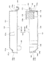
図12は本発明に係るガスボンベケースを分解した状態を示す断面図、図13は図11の13矢視図、図14は図11の14矢視図である。
下半割ケース131は、下前周壁部144の底部が、図12に示すように先端部144aが前方に向けて上り勾配で形成されている。
上り勾配で形成された先端部144aの頂部144b中央には、位置決め突部142が上方に向けて突出されている。
12 is a cross-sectional view showing a state in which the gas cylinder case according to the present invention is disassembled, FIG. 13 is a view taken along arrow 13 in FIG. 11, and FIG. 14 is a view taken along arrow 14 in FIG.
In the lower half case 131, the bottom portion of the lower front peripheral wall portion 144 is formed with an upward slope with the tip end portion 144a facing forward as shown in FIG.
A positioning projection 142 projects upward from the center of the top 144b of the tip 144a formed with an upward slope.

位置決め突部142には、フランジ95の切欠141(図9参照)が係合される。
切欠141を位置決め突部142に係合させることで、第2導入管部137の導入口137aを下方に向けた正規の取付位置にカセットガスボンベ21を位置決めすることができる。
A notch 141 (see FIG. 9) of the flange 95 is engaged with the positioning protrusion 142.
By engaging the notch 141 with the positioning protrusion 142, the cassette gas cylinder 21 can be positioned at a proper mounting position with the introduction port 137a of the second introduction pipe portion 137 facing downward.

また、下半割ケース131は、下前周壁部144の外面のうち、左周縁先端部144cに左ロック爪受部(ロック爪受部)156が設けられている。
また、下前周壁部144の外面のうち、右周縁先端部144dに右ロック爪受部(ロック爪受部)157が設けられている。
Further, the lower half case 131 is provided with a left lock claw receiving portion (lock claw receiving portion) 156 at the left peripheral edge tip portion 144c of the outer surface of the lower front peripheral wall portion 144.
In addition, a right lock claw receiving portion (lock claw receiving portion) 157 is provided at the right peripheral edge tip portion 144d of the outer surface of the lower front peripheral wall portion 144.

左右のロック爪受部156,157は、上半割ケース132に備えた左右のロック爪(ロック爪)158,159を受け入れる係止孔156a,157aがそれぞれ形成されている。
よって、左ロック爪受部156の係止孔156aに左ロック爪158を差し込むことにより、左ロック爪158を左ロック爪受部156に係止できる。
また、右ロック爪受部157の係止孔157aに右ロック爪159を差し込むことにより、右ロック爪159を右ロック爪受部157に係止できる。
これにより、下半割ケース131および上半割ケース132が組み合わされた状態に保持される。
The left and right lock claw receiving portions 156 and 157 are formed with locking holes 156a and 157a for receiving the left and right lock claws (lock claws) 158 and 159 provided in the upper half case 132, respectively.
Therefore, the left lock claw 158 can be locked to the left lock claw receiving portion 156 by inserting the left lock claw 158 into the locking hole 156 a of the left lock claw receiving portion 156.
Further, the right lock claw 159 can be locked to the right lock claw receiving portion 157 by inserting the right lock claw 159 into the locking hole 157 a of the right lock claw receiving portion 157.
Accordingly, the lower half case 131 and the upper half case 132 are held in a combined state.

下中央周壁部146の左側壁部位161は、図11に示すように、側面視で略矩形状に形成され、右側壁部位162は、左側壁部位161と左右対称に形成された壁部である。
左側壁部位161の外面には、左周縁中央部161aに左ストッパ部(ストッパ部)165が設けられ、右側壁部位162の外面には、右周縁中央部162aに右ストッパ部(ストッパ部)166が設けられている。
左右のストッパ部165,166は、上半割ケース132に備えた左右の係止部(係止部)167,168にそれぞれ当接可能な後壁部165a,166aを備えている。
As shown in FIG. 11, the left wall portion 161 of the lower central peripheral wall portion 146 is formed in a substantially rectangular shape in a side view, and the right wall portion 162 is a wall portion formed symmetrically with the left wall portion 161. .
A left stopper portion (stopper portion) 165 is provided on the left peripheral edge central portion 161a on the outer surface of the left side wall portion 161, and a right stopper portion (stopper portion) 166 is provided on the outer peripheral surface of the right wall portion 162 on the right peripheral edge central portion 162a. Is provided.
The left and right stopper portions 165 and 166 include rear wall portions 165a and 166a that can abut on left and right locking portions (locking portions) 167 and 168 provided in the upper half case 132, respectively.

左右のストッパ部165,166および左右の係止部167,168でズレ防止手段164が構成されている。
ズレ防止手段164は、掛止部42に保持ロッド41(図3参照)を掛止めした状態において、上半割ケース132が下半割ケース131に対して長手方向(前方に)にズレることを防ぐことができる。
The left and right stopper portions 165 and 166 and the left and right locking portions 167 and 168 constitute a deviation preventing means 164.
The slip prevention means 164 prevents the upper half case 132 from slipping in the longitudinal direction (forward) with respect to the lower half case 131 in a state where the holding rod 41 (see FIG. 3) is hooked on the hook portion 42. Can be prevented.

ズレ防止手段164を、下半割ケース131の左右のストッパ部165,166および上半割ケース132の左右の係止部167,168で構成した。
これにより、左右のストッパ部165,166および左右の係止部167,168の簡単な構成で、上下の半割ケース132,131、すなわちガスボンベケース26を良好に保持することができる。
The misalignment prevention means 164 includes left and right stopper portions 165 and 166 of the lower half case 131 and left and right locking portions 167 and 168 of the upper half case 132.
Accordingly, the upper and lower half cases 132 and 131, that is, the gas cylinder case 26 can be satisfactorily held by the simple configuration of the left and right stopper portions 165 and 166 and the left and right locking portions 167 and 168.

さらに、下後周壁部145の内面のうち、基端部に左右の突条部171,172が形成されている。左右の突条部171,172は下後壁部148から所定間隔をおいて形成されている。
よって、左突条部171および下後壁部148で左嵌合溝部(嵌合溝部)174が形成され、右突条部172および下後壁部148で右嵌合溝部(嵌合溝部)175が形成されている。
Furthermore, left and right protrusions 171 and 172 are formed at the base end portion of the inner surface of the lower rear peripheral wall portion 145. The left and right protrusions 171 and 172 are formed at a predetermined interval from the lower rear wall 148.
Therefore, a left fitting groove (fitting groove) 174 is formed by the left protrusion 171 and the lower rear wall 148, and a right fitting groove (fitting groove) 175 is formed by the right protrusion 172 and the lower rear wall 148. Is formed.

左右の嵌合溝部174,175にコイルばね部材133の基端部133aが嵌合されている。
基端部133aは、保持突起176に当接されている。よって、基端部133aが左右の嵌合溝部174,175から抜け出すことを保持突起176で防ぐことができる。
保持突起176は、下後壁部148の内面に形成されている。
The base end portion 133a of the coil spring member 133 is fitted into the left and right fitting groove portions 174, 175.
The base end portion 133 a is in contact with the holding protrusion 176. Therefore, the holding projection 176 can prevent the base end portion 133a from slipping out of the left and right fitting groove portions 174 and 175.
The holding protrusion 176 is formed on the inner surface of the lower rear wall portion 148.

このように、左右の嵌合溝部174,175にコイルばね部材133の基端部133aを嵌合し、この基端部133aを保持突起176で保持するようにした。
これにより、ガスボンベケース26内にコイルばね部材133を簡単な構成で設けることができる。
In this manner, the base end portion 133a of the coil spring member 133 is fitted into the left and right fitting groove portions 174 and 175, and the base end portion 133a is held by the holding protrusion 176.
Thereby, the coil spring member 133 can be provided in the gas cylinder case 26 with a simple configuration.

すなわち、コイルばね部材133は、基端部133aが下半割ケース131の基端部131a(ガスボンベケース26の基端部)に設けられ、先端部133bがカセットガスボンベ21の底部21a(図10参照)を押圧することで、カセットガスボンベ21を開口部126に向けて付勢するばねである。   That is, the coil spring member 133 has a base end portion 133a provided at the base end portion 131a of the lower half case 131 (base end portion of the gas cylinder case 26), and a tip end portion 133b of the bottom portion 21a of the cassette gas cylinder 21 (see FIG. 10). ) To urge the cassette gas cylinder 21 toward the opening 126.

図10に示すように、カセットガスボンベ21をコイルばね部材133で付勢することで、フランジ95を開口部126に対向させて外部に露出させた状態を確実に保つことができる。
さらに、カセットガスボンベ21をコイルばね部材133で付勢することで、作業機10の振動でカセットガスボンベ21が振れることを抑え、カセットガスボンベ21を安定的に支えることができる。
As shown in FIG. 10, by energizing the cassette gas cylinder 21 with the coil spring member 133, the state in which the flange 95 is opposed to the opening 126 and exposed to the outside can be reliably maintained.
Furthermore, by energizing the cassette gas cylinder 21 with the coil spring member 133, it is possible to suppress the cassette gas cylinder 21 from being shaken by the vibration of the work machine 10, and to stably support the cassette gas cylinder 21.

加えて、下半割ケース131は、左右の側壁部位161,162の外面のうち、下端先端部161b,162bに左右の前スライダ部(スライダ部)81,82が外方に向けて張り出されている。
左右の前スライダ部81,82は、下中央周壁部146の底部163(図15参照)と面一に形成されている。
In addition, the lower half case 131 has left and right front slider portions (slider portions) 81 and 82 projecting outward from the lower end tip portions 161b and 162b of the outer surfaces of the left and right side wall portions 161 and 162. ing.
The left and right front slider portions 81 and 82 are formed flush with the bottom portion 163 (see FIG. 15) of the lower central peripheral wall portion 146.

左右の前スライダ部81,82は、先端部81a,82aの幅寸法が先端に向けて徐々に小さくなるようにテーパ状に形成され、さらに、先端部81a,82aの厚さ寸法が先端に向けて徐々に小さくなるようにテーパ状に形成されている。   The left and right front slider portions 81 and 82 are formed in a tapered shape so that the width of the tip portions 81a and 82a gradually decreases toward the tip, and the thickness of the tip portions 81a and 82a is directed toward the tip. It is formed in a tapered shape so that it gradually becomes smaller.

また、左右の側壁部位161,162の外面のうち、下端基端部161c,162cに左右の後スライダ部(スライダ部)83,84が外方に向けて張り出されている。
左右の後スライダ部83,84は、左右の前スライダ部81,82と同じ形状に形成されている。
In addition, left and right rear slider portions (slider portions) 83 and 84 project outward from the lower end base end portions 161c and 162c of the outer surfaces of the left and right side wall portions 161 and 162, respectively.
The left and right rear slider portions 83 and 84 are formed in the same shape as the left and right front slider portions 81 and 82.

すなわち、左右の後スライダ部83,84は、下中央周壁部146の底部163(図15参照)と面一に形成されている。
また、左右の後スライダ部83,84は、先端部83a,84aの幅寸法が先端に向けて徐々に小さくなるようにテーパ状に形成され、さらに、先端部83a,84aの厚さ寸法が先端に向けて徐々に小さくなるようにテーパ状に形成されている。
That is, the left and right rear slider portions 83 and 84 are formed flush with the bottom portion 163 (see FIG. 15) of the lower central peripheral wall portion 146.
Further, the left and right rear slider portions 83 and 84 are formed in a tapered shape so that the width of the tip portions 83a and 84a gradually decreases toward the tip, and the thickness of the tip portions 83a and 84a is set to the tip. It is formed in a taper shape so that it gradually becomes smaller toward.

左右の前スライダ部81,82は、図6に示すレシーバ本体31に設けられた左右の前スライダガイド部75,65に摺動自在に差し込み可能な突片である。
左右の後スライダ部83,84は、図6に示すレシーバ本体31に設けられた左右の後スライダガイド部76,66に摺動自在に差し込み可能な突片である。
The left and right front slider portions 81 and 82 are projecting pieces that can be slidably inserted into the left and right front slider guide portions 75 and 65 provided in the receiver main body 31 shown in FIG.
The left and right rear slider portions 83 and 84 are projecting pieces that can be slidably inserted into the left and right rear slider guide portions 76 and 66 provided in the receiver main body 31 shown in FIG.

左右の前スライダ部81,82を左右の前スライダガイド部75,65に差し込み、左右の後スライダ部83,84を左右の後スライダガイド部76,66に差し込むことで、下半割ケース131がレシーバ本体31に着脱可能に設けられる。   The left and right front slider portions 81 and 82 are inserted into the left and right front slider guide portions 75 and 65, and the left and right rear slider portions 83 and 84 are inserted into the left and right rear slider guide portions 76 and 66. The receiver main body 31 is detachably provided.

前述したように、左右の前スライダ部81,82の先端部81a,82aや左右の後スライダ部83,84の先端部83a,84aをテーパ状に形成した。
よって、図6に示すレシーバ本体31の左右の前スライダガイド部75,65や左右の後スライダガイド部76,66に左右の前スライダ部81,82や左右の後スライダ部83,84を円滑に差し込むことができる。
As described above, the front end portions 81a and 82a of the left and right front slider portions 81 and 82 and the front end portions 83a and 84a of the left and right rear slider portions 83 and 84 are formed in a tapered shape.
Accordingly, the left and right front slider portions 81 and 82 and the left and right rear slider portions 83 and 84 are smoothly placed on the left and right front slider guide portions 75 and 65 and the left and right rear slider guide portions 76 and 66 of the receiver main body 31 shown in FIG. Can be plugged in.

下前壁部147は、車幅方向中央に上方に開口した半円弧状の下半開口部126b(図11も参照)が形成されている。
この下半開口部126bは、下半割ケース131の上半開口部126c(図11も参照)と組み合わされて開口部126(図9、図10参照)が形成される。
The lower front wall portion 147 is formed with a semicircular arc-shaped lower half opening 126b (see also FIG. 11) that opens upward in the center in the vehicle width direction.
The lower half opening 126b is combined with the upper half opening 126c (see also FIG. 11) of the lower half case 131 to form the opening 126 (see FIGS. 9 and 10).

下後壁部148は、周縁の左右端部148a,148bに左右の支え突片181,182が設けられ、左右の支え突片181,182にヒンジロッド183が架け渡されている。
ヒンジロッド183は、下後壁部148に対して所定間隔をおいて配置されるとともに、下後壁部148に対して平行に配置されている。
The lower rear wall 148 is provided with left and right support protrusions 181 and 182 at the left and right ends 148a and 148b of the periphery, and a hinge rod 183 is bridged between the left and right support protrusions 181 and 182.
The hinge rod 183 is disposed at a predetermined interval with respect to the lower rear wall portion 148 and is disposed in parallel with the lower rear wall portion 148.

ヒンジロッド183にヒンジ受部184が回動自在に連結されている。
よって、上下の半割ケース131,132をヒンジロッド183およびヒンジ受部184を連結した状態で、上半割ケース132をヒンジロッド183を軸にして開閉することが可能になる。
A hinge receiving portion 184 is rotatably connected to the hinge rod 183.
Therefore, it is possible to open and close the upper half case 132 around the hinge rod 183 with the upper and lower half cases 131 and 132 connected to the hinge rod 183 and the hinge receiving portion 184.

上半割ケース132は、上周壁部151の先端部151aのうち、頂部151bが、図12に示すように先端に向けて下り勾配で形成されている。
また、上半割ケース132は、上周壁部151の外面のうち、左周縁先端部151cに左ロック爪158が設けられている。
また、上周壁部151の外面のうち、右周縁先端部151dに右ロック爪159が設けられている。
左ロック爪158は、図15に示すように、上端部158aを支点にして左右方向に弾性変形可能で、下端部に張出爪部158bが形成されている。
As for the upper half case 132, the top part 151b is formed in the downward slope toward the front-end | tip among the front-end | tip parts 151a of the upper peripheral wall part 151, as shown in FIG.
Further, the upper half case 132 has a left lock claw 158 provided at the front end portion 151 c of the left peripheral edge of the outer surface of the upper peripheral wall portion 151.
In addition, a right lock claw 159 is provided at the right peripheral edge tip portion 151 d of the outer surface of the upper peripheral wall portion 151.
As shown in FIG. 15, the left lock claw 158 can be elastically deformed in the left-right direction with the upper end portion 158a as a fulcrum, and an overhang claw portion 158b is formed at the lower end portion.

右ロック爪159は、図15に示すように、左ロック爪158と左右対称の部材である。
右ロック爪159は、上端部159aを支点にして左右方向に弾性変形可能で、下端部に張出爪部159bが形成されている。
なお、左右のロック爪158,159を左右のロック爪受部156,157に係止する例について図15で詳しく説明する。
As shown in FIG. 15, the right lock claw 159 is a member symmetrical to the left lock claw 158.
The right lock claw 159 can be elastically deformed in the left-right direction with the upper end 159a as a fulcrum, and an overhang claw 159b is formed at the lower end.
An example in which the left and right lock claws 158 and 159 are engaged with the left and right lock claw receiving portions 156 and 157 will be described in detail with reference to FIG.

上周壁部151の外面には、左周縁中央部151eに左係止部167が設けられ、右周縁中央部151fに右係止部168が設けられている。
左係止部167が左ストッパ部165の後壁部165a(図13参照)に当接され、右係止部168が右ストッパ部166の後壁部166a(図13参照)に当接されている。
なお、左右の係止部167,168を左右のストッパ部165,166の後壁部165a,166aに当接する理由については図17(b)で詳しく説明する。
On the outer surface of the upper peripheral wall portion 151, a left locking portion 167 is provided at the left peripheral edge central portion 151e, and a right locking portion 168 is provided at the right peripheral edge central portion 151f.
The left locking portion 167 is in contact with the rear wall portion 165a (see FIG. 13) of the left stopper portion 165, and the right locking portion 168 is in contact with the rear wall portion 166a (see FIG. 13) of the right stopper portion 166. Yes.
The reason why the left and right engaging portions 167 and 168 are in contact with the rear wall portions 165a and 166a of the left and right stopper portions 165 and 166 will be described in detail with reference to FIG.

上前壁部152は、車幅方向中央に下方に開口した半円弧状の上半開口部126c(図11も参照)が形成されている。
この上半開口部126cは、前述したように、下半割ケース131の下半開口部126b(図11参照)と組み合わされて開口部126(図9、図11参照)が形成される。
The upper front wall 152 is formed with a semicircular arc upper half opening 126c (see also FIG. 11) that opens downward in the center in the vehicle width direction.
As described above, the upper half opening 126c is combined with the lower half opening 126b (see FIG. 11) of the lower half case 131 to form the opening 126 (see FIGS. 9 and 11).

上後壁部153は、周縁部153aにヒンジ受部184が設けられている。ヒンジ受部184は、ヒンジロッド183に係止可能に断面略U字状に形成されている。
ヒンジ受部184をヒンジロッド183に係止することで、ヒンジロッド183にヒンジ受部184を回動自在に連結することが可能である。
よって、前述したように、上下の半割ケース131,132をヒンジロッド183およびヒンジ受部184を連結した状態で、上半割ケース132をヒンジロッド183を軸にして開閉することが可能になる。
The upper rear wall portion 153 is provided with a hinge receiving portion 184 at the peripheral edge portion 153a. The hinge receiving portion 184 is formed in a substantially U-shaped cross section so that it can be locked to the hinge rod 183.
By locking the hinge receiving portion 184 to the hinge rod 183, the hinge receiving portion 184 can be rotatably connected to the hinge rod 183.
Therefore, as described above, the upper half case 132 can be opened and closed around the hinge rod 183 with the upper and lower half cases 131 and 132 connected to the hinge rod 183 and the hinge receiving portion 184. .

また、上周壁部151は、図11に示すように、中央部151gに掛止部42が設けられている。
掛止部42は、図10に示すように、左右の掛止部185,186を有している。
左掛止部185は、上周壁部151の中部左側部151hから外方に向けて山形に隆起された部位である。
Moreover, as shown in FIG. 11, the upper peripheral wall part 151 is provided with the latch part 42 in the center part 151g.
As shown in FIG. 10, the latching portion 42 has left and right latching portions 185 and 186.
The left hooking portion 185 is a portion raised in a mountain shape outward from the middle left portion 151h of the upper peripheral wall portion 151.

右掛止部186は、上周壁部151の中部右側部151iから外方に向けて山形に隆起された部位である。
左右の掛止部185,186に、図3に示す保持ロッド41(具体的には、左右のフック部108,109)をそれぞれ掛け止めることができる。
The right hooking portion 186 is a portion that is raised in a mountain shape outward from the middle right portion 151i of the upper peripheral wall portion 151.
The holding rod 41 shown in FIG. 3 (specifically, the left and right hook portions 108 and 109) can be hooked on the left and right hook portions 185 and 186, respectively.

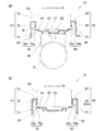
図15は図3の15−15線断面図、図16(a)は図15の16a部拡大図、図16(b)は(a)の構成を分解した状態を示す図である。
ここで、下半割ケース131の上辺191には、略矩形状全周に亘って下ケース段部(段部)192が形成されている。
また、上半割ケース132の下辺194には、略矩形状全周に亘って上ケース段部(段部)195が形成されている。
15 is a cross-sectional view taken along the line 15-15 in FIG. 3, FIG. 16 (a) is an enlarged view of the portion 16a in FIG. 15, and FIG. 16 (b) is a diagram showing a state in which the configuration of FIG.
Here, a lower case step portion (step portion) 192 is formed on the upper side 191 of the lower half case 131 over the entire circumference of a substantially rectangular shape.
Further, an upper case step portion (step portion) 195 is formed on the lower side 194 of the upper half case 132 over the entire circumference of a substantially rectangular shape.

上下の半割ケース131,132を組み付けた状態で、上ケース段部195に上辺191の凸角部193が当接し、下ケース段部192に下辺194の凸角部196が当接する。
よって、下半割ケース131の上辺191および上半割ケース132の下辺194の合わせ部198を略クランク状に折り曲げられたラビリンス構造とすることができる。
これにより、合わせ部198の耐水性が高められ、ガスボンベケース26内に水が侵入することを防ぐことができる。
With the upper and lower halved cases 131 and 132 assembled, the convex corner portion 193 of the upper side 191 contacts the upper case step portion 195, and the convex corner portion 196 of the lower side 194 contacts the lower case step portion 192.
Therefore, a labyrinth structure in which the mating portion 198 of the upper side 191 of the lower half case 131 and the lower side 194 of the upper half case 132 is bent into a substantially crank shape can be obtained.
As a result, the water resistance of the mating portion 198 is increased, and water can be prevented from entering the gas cylinder case 26.

つぎに、レシーバ25にガスボンベケース26を取り付ける手順を図17〜図19に基づいて詳しく説明する。
図17(a),(b)は本発明に係るレシーバにガスボンベケースを取り付ける手順を説明する図である。
なお、レシーバ25やガスボンベケース26は略左右対称の部材なので、図17においては右側部材について説明して左側部材の説明を省略する。
Next, a procedure for attaching the gas cylinder case 26 to the receiver 25 will be described in detail with reference to FIGS.
FIGS. 17A and 17B are views for explaining the procedure for attaching the gas cylinder case to the receiver according to the present invention.
Since the receiver 25 and the gas cylinder case 26 are substantially symmetrical members, the right side member will be described in FIG. 17 and the description of the left side member will be omitted.

(a)において、レシーバ25にガスボンベケース26を取り付ける際には、まず、保持ロッド41をロックばね部材105(図3参照)の付勢力に抗して開放位置P2に保持する。
切替バルブ38は燃料遮断状態、すなわち燃料遮断位置P4に配置されている。
In (a), when attaching the gas cylinder case 26 to the receiver 25, first, the holding rod 41 is held at the open position P2 against the urging force of the lock spring member 105 (see FIG. 3).
The switching valve 38 is disposed in the fuel cutoff state, that is, the fuel cutoff position P4.

この状態で、レシーバ25のレシーバ本体31の上方にガスボンベケース26を配置する。
つぎに、ガスボンベケース26の右前スライダ部82を右案内溝64の傾斜面64aに沿わせて矢印Aの如く移動する。
同時に、ガスボンベケース26の右後スライダ部84を矢印Bの如く移動する。
In this state, the gas cylinder case 26 is disposed above the receiver main body 31 of the receiver 25.
Next, the right front slider portion 82 of the gas cylinder case 26 is moved along the inclined surface 64a of the right guide groove 64 as indicated by an arrow A.
At the same time, the right rear slider portion 84 of the gas cylinder case 26 is moved as indicated by an arrow B.

右前スライダ部82が底部44に当接し、右前スライダガイド部65の差込口65c後方に位置する。
同時に、右後スライダ部84が右後スライダガイド部66の差込口66c後方に位置する。
この状態で、レシーバ本体31の底部44にガスボンベケース26の底部163(図15も参照)が載置される。
The right front slider portion 82 is in contact with the bottom portion 44 and is located behind the insertion port 65c of the right front slider guide portion 65.
At the same time, the right rear slider portion 84 is positioned behind the insertion port 66 c of the right rear slider guide portion 66.
In this state, the bottom portion 163 (see also FIG. 15) of the gas cylinder case 26 is placed on the bottom portion 44 of the receiver main body 31.

ガスボンベケース26を前方に移動することで、右前スライダ部82が差込口65cから右前スライダガイド部65内に矢印Cの如く進入する。
同時に、右後スライダ部84が差込口66cから右後スライダガイド部66に矢印Dの如く進入する。
By moving the gas cylinder case 26 forward, the right front slider portion 82 enters the right front slider guide portion 65 from the insertion port 65c as indicated by an arrow C.
At the same time, the right rear slider portion 84 enters the right rear slider guide portion 66 from the insertion port 66c as indicated by an arrow D.

これにより、右前スライダ部82が右前スライダガイド部65で支持されるとともに、右後スライダ部84が右後スライダガイド部66に支持され、レシーバ本体31にガスボンベケース26が取付位置に位置決めされる。   As a result, the right front slider portion 82 is supported by the right front slider guide portion 65, the right rear slider portion 84 is supported by the right rear slider guide portion 66, and the gas cylinder case 26 is positioned at the mounting position on the receiver body 31.

このように、ガスボンベケース26を前方に移動させて、右前スライダ部82を右前スライダガイド部65内に進入させるとともに、右後スライダ部84を右後スライダガイド部66に進入させる簡単な操作で、ガスボンベケース26を所定の取付位置に位置決めすることができる。
これにより、ガスボンベケース26のレシーバ25(レシーバ本体31)に対する位置決めが容易になる。
As described above, the gas cylinder case 26 is moved forward to allow the front right slider portion 82 to enter the right front slider guide portion 65 and the right rear slider portion 84 to enter the right rear slider guide portion 66. The gas cylinder case 26 can be positioned at a predetermined mounting position.
Thereby, positioning with respect to the receiver 25 (receiver main body 31) of the gas cylinder case 26 becomes easy.

ここで、ガスボンベケース26にはカセットガスボンベ21が収容されている。
カセットガスボンベ21は、図9に示すように、フランジ95の切欠141が位置決め突部142に係合されることで正規の取付位置に位置決めされている。
よって、ガスボンベケース26を位置決めすることで、カセットガスボンベ21をレシーバ25(レシーバ本体31)に対して正確に位置決めすることができる。
Here, the cassette gas cylinder 21 is accommodated in the gas cylinder case 26.
As shown in FIG. 9, the cassette gas cylinder 21 is positioned at the proper mounting position by engaging the notch 141 of the flange 95 with the positioning protrusion 142.
Therefore, by positioning the gas cylinder case 26, the cassette gas cylinder 21 can be accurately positioned with respect to the receiver 25 (receiver body 31).

(b)において、保持ロッド41をロックばね部材105(図3参照)の付勢力で矢印Eの如く保持位置P1まで戻す。
左右のフック部108,109を掛止部42(左右の掛止部185,186)に掛け止める。
左右のフック部108,109を掛止部42(左右の掛止部185,186)に掛け止めることで、ガスボンベケース26が後方に移動しないように保持することができる。
これにより、レシーバ25にガスボンベケース26が取り付けられる。
In (b), the holding rod 41 is returned to the holding position P1 as shown by the arrow E by the urging force of the lock spring member 105 (see FIG. 3).
The left and right hook portions 108 and 109 are hooked on the hook portion 42 (left and right hook portions 185 and 186).
The gas cylinder case 26 can be held so as not to move backward by hooking the left and right hook portions 108 and 109 to the hook portion 42 (left and right hook portions 185 and 186).
As a result, the gas cylinder case 26 is attached to the receiver 25.

ここで、ズレ防止手段164は、左ストッパ部165の後壁部165aに左係止部167が係止し、右ストッパ部166の後壁部166aに右係止部168が係止している。
よって、掛止部42に保持ロッドを掛止めした状態において、上半割ケース132が下半割ケース131に対して長手方向(前方に)にズレることを防ぐことができる。
これにより、上下の半割ケース132,131、すなわちガスボンベケース26を保持ロッド41で良好に保持することができる。
Here, in the slip prevention means 164, the left locking portion 167 is locked to the rear wall portion 165a of the left stopper portion 165, and the right locking portion 168 is locked to the rear wall portion 166a of the right stopper portion 166. .
Therefore, it is possible to prevent the upper half case 132 from shifting in the longitudinal direction (forward) with respect to the lower half case 131 in a state where the holding rod is hooked on the hook portion 42.
Accordingly, the upper and lower half cases 132 and 131, that is, the gas cylinder case 26 can be favorably held by the holding rod 41.

図18(a),(b)は本発明に係るスライダガイド部にスライダ部を差し込んだ状態に保持した状態を示す図である。
(a)において、左後スライダ部83が左後スライダガイド部76に保持した状態に保たれている。
また、右後スライダ部84が右後スライダガイド部66に保持した状態に保たれている。
18 (a) and 18 (b) are views showing a state in which the slider portion is inserted and held in the slider guide portion according to the present invention.
In (a), the left rear slider portion 83 is held in the state held by the left rear slider guide portion 76.
Further, the right rear slider portion 84 is held in the state held by the right rear slider guide portion 66.

(b)において、左前スライダ部81が左前スライダガイド部75に保持した状態に保たれている。
また、右前スライダ部82が右前スライダガイド部65に保持した状態に保たれている。
これにより、ガスボンベケース26をレシーバ25(レシーバ本体31)に取り付けた状態に保持することができる。
In (b), the left front slider portion 81 is held in the state held by the left front slider guide portion 75.
Further, the right front slider portion 82 is held in the right front slider guide portion 65.
Thereby, the gas cylinder case 26 can be held in a state of being attached to the receiver 25 (receiver main body 31).

図19は本発明に係る切替バルブを燃料供給状態に切り替える例を説明する図である。
切替バルブ38の操作レバー98を操作者が操作して、燃料遮断位置P4から燃料供給位置P3まで矢印Fの如く移動する。
これにより、切替バルブ38が、図1に示すガスエンジン12に燃料24(図10参照)を供給する燃料供給状態に保持され、ガスエンジン12の始動が可能になる。
この状態で、操作レバー98の従動係止片118が駆動突片116(駆動係止片122や張出片121)に上方から当接する。
FIG. 19 is a diagram illustrating an example in which the switching valve according to the present invention is switched to the fuel supply state.
The operator operates the operation lever 98 of the switching valve 38 to move from the fuel cutoff position P4 to the fuel supply position P3 as indicated by an arrow F.
Thereby, the switching valve 38 is maintained in a fuel supply state in which the fuel 24 (see FIG. 10) is supplied to the gas engine 12 shown in FIG. 1, and the gas engine 12 can be started.
In this state, the driven locking piece 118 of the operation lever 98 comes into contact with the driving protrusion 116 (the driving locking piece 122 and the overhanging piece 121) from above.

このように、ガスエンジン12を始動する際に、操作レバー98を燃料供給位置P3まで操作者が操作して切替バルブ38を燃料供給状態に切り替えるようにした。
これにより、ガスエンジン12の始動時の作業者への意識高揚を図ることができる。
Thus, when starting the gas engine 12, the operator operates the operation lever 98 to the fuel supply position P3 to switch the switching valve 38 to the fuel supply state.
As a result, it is possible to raise the awareness of the operator when starting the gas engine 12.

ついで、レシーバ25からガスボンベケース26を取り外す手順を図20に基づいて詳しく説明する。
図20(a),(b)は本発明に係る切替バルブを保持ロッドに連動させて燃料遮断状態に切り替える例を説明する図である。
(a)において、保持ロッド41を掛止部42から外して開放位置P2に向けて矢印Gの如く持ち上げる。
駆動突片116が保持ロッド41とともに矢印Gの如く移動する。
Next, a procedure for removing the gas cylinder case 26 from the receiver 25 will be described in detail with reference to FIG.
FIGS. 20A and 20B are diagrams illustrating an example in which the switching valve according to the present invention is switched to the fuel cutoff state in conjunction with the holding rod.
In (a), the holding rod 41 is removed from the latching portion 42 and lifted as shown by the arrow G toward the open position P2.
The drive protrusion 116 moves along with the holding rod 41 as shown by an arrow G.

駆動突片116が移動することで、従動突部114の従動係止片118が駆動突片116で押し上げられて矢印Hの如く移動する。
よって、駆動突片116で従動突部114(従動係止片118)を移動させて、操作レバー98を燃料遮断位置P4まで連動させることができる。
As the driving protrusion 116 moves, the driven locking piece 118 of the driven protrusion 114 is pushed up by the driving protrusion 116 and moves as indicated by an arrow H.
Therefore, the driven protrusion 114 (driven locking piece 118) can be moved by the drive protrusion 116, and the operation lever 98 can be interlocked to the fuel cutoff position P4.

このように、保持ロッド41に駆動突片116を備え、操作レバー98に従動突部114を備えるだけの簡単な構成で、保持ロッド41の移動に連動させて切替バルブ38を燃料供給状態から燃料遮断状態に切り替えることができる。   As described above, the switching rod 38 is moved from the fuel supply state to the fuel supply state in conjunction with the movement of the holding rod 41 with a simple configuration in which the holding rod 41 is provided with the driving protrusion 116 and the operation lever 98 is provided with the driven protrusion 114. It can be switched to the blocking state.

(b)において、保持ロッド41(左右のフック部108,109)を掛止部42(左右の掛止部185,186)から外すことで、ガスボンベケース26が矢印I方向に移動可能となる。
ガスボンベケース26を矢印Iの如く移動することで、ガスボンベケース26をレシーバ25のレシーバ本体31から取り外すことができる。
In (b), the gas cylinder case 26 can be moved in the direction of arrow I by removing the holding rod 41 (the left and right hook portions 108, 109) from the hook portion 42 (the left and right hook portions 185, 186).
The gas cylinder case 26 can be detached from the receiver main body 31 of the receiver 25 by moving the gas cylinder case 26 as shown by the arrow I.

このように、保持ロッド41をロックばね部材105(図3参照)の付勢力に抗して掛止部42から外すだけで、ガスボンベケース26をレシーバ本体31から簡単に取り外すことができるので、使い勝手の向上を図ることができる。   As described above, the gas cylinder case 26 can be easily detached from the receiver body 31 simply by removing the holding rod 41 from the latching portion 42 against the urging force of the lock spring member 105 (see FIG. 3). Can be improved.

ここで、保持ロッド41の移動に連動させて切替バルブ38が燃料遮断状態に切り替えられている。
よって、図17に示すカセットガスボンベ21のノズル87を口金支え部37から外すときに、カセットガスボンベ21内の燃料24(図10参照)がノズル87から流出する虞がない。
Here, the switching valve 38 is switched to the fuel cutoff state in conjunction with the movement of the holding rod 41.
Therefore, when the nozzle 87 of the cassette gas cylinder 21 shown in FIG. 17 is removed from the base support portion 37, there is no possibility that the fuel 24 (see FIG. 10) in the cassette gas cylinder 21 flows out of the nozzle 87.

図20で説明したように、保持ロッド41によるガスボンベケース26(カセットガスボンベ21)の保持を解除する際に、保持ロッド41の移動に連動させて切替バルブ38を燃料供給状態から燃料遮断状態に切替可能とした。   As described with reference to FIG. 20, when releasing the holding of the gas cylinder case 26 (cassette gas cylinder 21) by the holding rod 41, the switching valve 38 is switched from the fuel supply state to the fuel cutoff state in conjunction with the movement of the holding rod 41. It was possible.

よって、ガスボンベケース26(カセットガスボンベ21)をレシーバ25のレシーバ本体31から取り外す際に、切替バルブ38を個別に操作して燃料供給状態から燃料遮断状態に切り替える必要がない。
これにより、レシーバ本体31からガスボンベケース26(カセットガスボンベ21)を取り外す際に、簡単な操作手順で取り外すことができ、使い勝手の向上を図ることができる。
Therefore, when removing the gas cylinder case 26 (cassette gas cylinder 21) from the receiver body 31 of the receiver 25, it is not necessary to individually operate the switching valve 38 to switch from the fuel supply state to the fuel cutoff state.
Thereby, when removing the gas cylinder case 26 (cassette gas cylinder 21) from the receiver main body 31, it can be removed by a simple operation procedure, and the usability can be improved.

なお、前記実施の形態では、カセットガスボンベ取付構造20を適用する作業機10として歩行型耕耘機を例示したが、作業機はこれに限定するものではなく、芝刈機、船外機、発電機などの他の作業機に適用することも可能である。   In the above-described embodiment, the walking type tiller is exemplified as the working machine 10 to which the cassette gas cylinder mounting structure 20 is applied. However, the working machine is not limited thereto, and a lawn mower, an outboard motor, a generator, and the like. It is also possible to apply to other working machines.

また、前記実施の形態では、コイルばね部材133を下半割ケース131の基端部131aに取り付けた例について説明したが、これに限らないで、コイルばね部材133を上半割ケース132の基端部に取り付けることも可能である。   In the above embodiment, the example in which the coil spring member 133 is attached to the base end portion 131a of the lower half case 131 has been described. It can also be attached to the end.

さらに、前記実施の形態で示したカセットガスボンベ21、ガスボンベケース26、レシーバ本体31、口金支え部37、保持ロッド41、掛止部42、フランジ受部92、フランジ95、開口部126、下半割ケース131、上半割ケース132、コイルばね部材133、左嵌合溝部174、右嵌合溝部175、保持突起176などは例示した形状に限定するものではなく適宜変更が可能である。   Furthermore, the cassette gas cylinder 21, the gas cylinder case 26, the receiver main body 31, the base support portion 37, the holding rod 41, the latching portion 42, the flange receiving portion 92, the flange 95, the opening portion 126, and the lower half of the above-described embodiment. The case 131, the upper half case 132, the coil spring member 133, the left fitting groove 174, the right fitting groove 175, the holding protrusion 176, and the like are not limited to the illustrated shapes, and can be appropriately changed.

本発明は、作業機のエンジンに燃料を供給するカセットガスボンベをカセットガスボンベ取付構造で取り付けるように構成した作業機への適用に好適である。   INDUSTRIAL APPLICABILITY The present invention is suitable for application to a working machine configured such that a cassette gas cylinder that supplies fuel to the engine of the working machine is attached with a cassette gas cylinder mounting structure.

本発明に係る作業機のカセットガスボンベ取付構造を示す側面図である。It is a side view which shows the cassette gas cylinder attachment structure of the working machine which concerns on this invention. 本発明に係るカセットガスボンベ取付構造を示す斜視図である。It is a perspective view which shows the cassette gas cylinder attachment structure which concerns on this invention. 本発明に係るカセットガスボンベ取付構造のレシーバからガスボンベケースを取り外した状態を示す斜視図である。It is a perspective view which shows the state which removed the gas cylinder case from the receiver of the cassette gas cylinder attachment structure which concerns on this invention. 本発明に係るレシーバのレシーバ本体を示す斜視図である。It is a perspective view which shows the receiver main body of the receiver which concerns on this invention. 本発明に係るレシーバ本体を示す平面図である。It is a top view which shows the receiver main body which concerns on this invention. (a)は図5の6a−6a線断面図、(b)は図5の6b−6b線断面図である。(A) is the sectional view on the 6a-6a line of FIG. 5, (b) is the sectional view on the 6b-6b line of FIG. 本発明に係るレシーバの口金支え部および切替バルブを示す斜視図である。It is a perspective view which shows the nozzle | cap | die support part and switching valve of the receiver which concern on this invention. 本発明に係るレシーバの口金支え部でカセットガスボンベの口金部を支えた状態を示す断面図である。It is sectional drawing which shows the state which supported the base part of the cassette gas cylinder with the base support part of the receiver which concerns on this invention. 本発明に係るカセットガスボンベ取付構造のガスボンベケースを示す斜視図である。It is a perspective view which shows the gas cylinder case of the cassette gas cylinder attachment structure which concerns on this invention. 本発明に係るガスボンベケースを示す断面図である。It is sectional drawing which shows the gas cylinder case which concerns on this invention. 本発明に係るガスボンベケースを示す分解斜視図である。It is a disassembled perspective view which shows the gas cylinder case which concerns on this invention. 本発明に係るガスボンベケースを分解した状態を示す断面図である。It is sectional drawing which shows the state which decomposed | disassembled the gas cylinder case which concerns on this invention. 図11の13矢視図である。FIG. 13 is a view taken in the direction of arrow 13 in FIG. 11. 図11の14矢視図である。It is a 14 arrow line view of FIG. 図3の15−15線断面図である。FIG. 15 is a cross-sectional view taken along line 15-15 in FIG. 3. (a)は図15の16a部拡大図、(b)は(a)の構成を分解した状態を示す図である。(A) is the 16a part enlarged view of FIG. 15, (b) is a figure which shows the state which decomposed | disassembled the structure of (a). 本発明に係るレシーバにガスボンベケースを取り付ける手順を説明する図である。It is a figure explaining the procedure which attaches a gas cylinder case to the receiver which concerns on this invention. 本発明に係るスライダガイド部にスライダ部を差し込んだ状態に保持した状態を示す図である。It is a figure which shows the state hold | maintained in the state which inserted the slider part in the slider guide part which concerns on this invention. 本発明に係る切替バルブを燃料供給状態に切り替える例を説明する図である。It is a figure explaining the example which switches the switching valve which concerns on this invention to a fuel supply state. 本発明に係る切替バルブを保持ロッド41に連動させて燃料遮断状態に切り替える例を説明する図である。It is a figure explaining the example which switches the switching valve which concerns on this invention to the fuel cutoff state in response to the holding rod.

符号の説明Explanation of symbols

10…作業機、11…作業機本体、12…ガスエンジン(エンジン)、20…作業機のカセットガスボンベ取付構造、21…カセットガスボンベ、24…燃料、26…ガスボンベケース、26a…ガスボンベケースの先端部、37…口金支え部、41…保持ロッド(保持部材)、42…掛止部、86…口金部、92…フランジ受部、95…フランジ、126…開口部、131…下半割ケース、131a…下半割ケースの基端部(ガスボンベケース26の基端部)、132…上半割ケース、133…コイルばね部材(弾性部材)、133a…コイルばね部材の基端部、174…左嵌合溝部(嵌合溝部)、175…右嵌合溝部(嵌合溝部)、176…保持突起。   DESCRIPTION OF SYMBOLS 10 ... Working machine, 11 ... Working machine main body, 12 ... Gas engine (engine), 20 ... Cassette gas cylinder mounting structure of a working machine, 21 ... Cassette gas cylinder, 24 ... Fuel, 26 ... Gas cylinder case, 26a ... Tip part of gas cylinder case , 37 ... base support part, 41 ... holding rod (holding member), 42 ... latching part, 86 ... base part, 92 ... flange receiving part, 95 ... flange, 126 ... opening part, 131 ... lower half case, 131a ... Base end part of the lower half case (base end part of the gas cylinder case 26), 132 ... Upper half case, 133 ... Coil spring member (elastic member), 133a ... Base end part of the coil spring member, 174 ... Left fitting Fitting groove (fitting groove), 175... Right fitting groove (fitting groove), 176.

Claims (4)

作業機本体に搭載されたエンジンに燃料を供給するカセットガスボンベを取り付ける作業機のカセットガスボンベ取付構造において、
作業機側に前記カセットガスボンベの口金部を支える口金支え部を備え、
前記口金支え部に、前記口金部の外周に沿って形成されたフランジが当接可能なフランジ受部を備えたことを特徴とする作業機のカセットガスボンベ取付構造。
In the cassette gas cylinder mounting structure of the work machine for attaching the cassette gas cylinder for supplying fuel to the engine mounted on the work machine body,
Provided with a base support part for supporting the base part of the cassette gas cylinder on the work machine side,
A cassette gas cylinder mounting structure for a working machine, wherein the base support portion includes a flange receiving portion on which a flange formed along the outer periphery of the base portion can abut.
前記カセットガスボンベを収容した状態で前記作業機側に取付け可能なガスボンベケースを備え、
前記ガスボンベケースの先端部に、前記カセットガスボンベの前記フランジを外部に露出させる開口部を備え、
前記ガスボンベケースの基端部側に、前記カセットガスボンベを前記開口部に向けて付勢する弾性部材を備えたことを特徴とする請求項1記載のカセットガスボンベ取付構造。
A gas cylinder case that can be attached to the working machine side in a state in which the cassette gas cylinder is accommodated,
The front end portion of the gas cylinder case includes an opening that exposes the flange of the cassette gas cylinder to the outside,
2. The cassette gas cylinder mounting structure according to claim 1, further comprising an elastic member that urges the cassette gas cylinder toward the opening on the base end side of the gas cylinder case.
前記作業機側に設けられて前記ガスボンベケースを保持可能な保持部材と、
前記ガスボンベケースに設けられて前記保持部材が掛止め可能な掛止部と、
を備え、
前記掛止部に掛け止めした前記保持部材で前記ガスボンベケースを前記フランジ受部に向けて付勢することで、前記フランジを前記フランジ受部に当接させることを特徴とする請求項2記載の作業機のカセットガスボンベ取付構造。
A holding member provided on the work machine side and capable of holding the gas cylinder case;
A latching portion provided in the gas cylinder case and capable of latching the holding member;
With
3. The flange according to claim 2, wherein the flange is brought into contact with the flange receiving portion by urging the gas cylinder case toward the flange receiving portion with the holding member latched to the retaining portion. Installation structure of cassette gas cylinder for work equipment.
前記弾性部材としてコイルばね部材が用いられ、
前記上半割ケースおよび前記下半割ケースのいずれか一方の基端部に、前記コイルばね部材の基端部を嵌合する嵌合溝部が設けられ、
前記一方の基端部に、前記コイルばね部材の基端部を前記嵌合溝部に嵌合した状態に保持する保持突起が設けられたことを特徴とする請求項2または請求項3記載の作業機のカセットガスボンベ取付構造。
A coil spring member is used as the elastic member,
A fitting groove for fitting a proximal end portion of the coil spring member is provided at one of the proximal end portions of the upper half case and the lower half case,
The work according to claim 2 or 3, wherein a holding projection for holding the base end portion of the coil spring member in a state of being fitted in the fitting groove portion is provided on the one base end portion. Machine cassette gas cylinder mounting structure.
JP2008140019A 2008-05-28 2008-05-28 Cassette gas cylinder mounting structure for work equipment Active JP4619423B2 (en)

Priority Applications (7)

Application Number Priority Date Filing Date Title
JP2008140019A JP4619423B2 (en) 2008-05-28 2008-05-28 Cassette gas cylinder mounting structure for work equipment
US12/471,001 US8307803B2 (en) 2008-05-28 2009-05-22 Work machine
TW098117138A TWI386550B (en) 2008-05-28 2009-05-22 Work machine
CN200910203579.0A CN101590809B (en) 2008-05-28 2009-05-27 Work machine
EP09161185A EP2128513B1 (en) 2008-05-28 2009-05-27 Work machine with gas cassette
KR1020090046658A KR101049213B1 (en) 2008-05-28 2009-05-27 Working machine
DE602009000332T DE602009000332D1 (en) 2008-05-28 2009-05-27 Work machine with gas cassette

Applications Claiming Priority (1)

Application Number Priority Date Filing Date Title
JP2008140019A JP4619423B2 (en) 2008-05-28 2008-05-28 Cassette gas cylinder mounting structure for work equipment

Publications (2)

Publication Number Publication Date
JP2009286232A true JP2009286232A (en) 2009-12-10
JP4619423B2 JP4619423B2 (en) 2011-01-26

Family

ID=41455878

Family Applications (1)

Application Number Title Priority Date Filing Date
JP2008140019A Active JP4619423B2 (en) 2008-05-28 2008-05-28 Cassette gas cylinder mounting structure for work equipment

Country Status (1)

Country Link
JP (1) JP4619423B2 (en)

Cited By (1)

* Cited by examiner, † Cited by third party
Publication number Priority date Publication date Assignee Title
JP2011143863A (en) * 2010-01-16 2011-07-28 Mitsubishi Agricultural Machinery Co Ltd Gas engine type management machine

Citations (6)

* Cited by examiner, † Cited by third party
Publication number Priority date Publication date Assignee Title
JPH0324966U (en) * 1989-07-20 1991-03-14
JPH0622762U (en) * 1992-04-03 1994-03-25 新富士バーナー株式会社 Gas filling device
JPH0737562A (en) * 1993-07-22 1995-02-07 Sharp Corp Battery housing device
JPH07117496A (en) * 1993-10-20 1995-05-09 Nissan Motor Co Ltd Simple-type lpg cylinder attaching structure
JPH10131809A (en) * 1996-10-30 1998-05-19 Honda Motor Co Ltd Gas engine and gas engine working machine
JP3469019B2 (en) * 1996-12-10 2003-11-25 三菱重工業株式会社 Cylinder holder for small gas engine

Patent Citations (6)

* Cited by examiner, † Cited by third party
Publication number Priority date Publication date Assignee Title
JPH0324966U (en) * 1989-07-20 1991-03-14
JPH0622762U (en) * 1992-04-03 1994-03-25 新富士バーナー株式会社 Gas filling device
JPH0737562A (en) * 1993-07-22 1995-02-07 Sharp Corp Battery housing device
JPH07117496A (en) * 1993-10-20 1995-05-09 Nissan Motor Co Ltd Simple-type lpg cylinder attaching structure
JPH10131809A (en) * 1996-10-30 1998-05-19 Honda Motor Co Ltd Gas engine and gas engine working machine
JP3469019B2 (en) * 1996-12-10 2003-11-25 三菱重工業株式会社 Cylinder holder for small gas engine

Cited By (1)

* Cited by examiner, † Cited by third party
Publication number Priority date Publication date Assignee Title
JP2011143863A (en) * 2010-01-16 2011-07-28 Mitsubishi Agricultural Machinery Co Ltd Gas engine type management machine

Also Published As

Publication number Publication date
JP4619423B2 (en) 2011-01-26

Similar Documents

Publication Publication Date Title
EP2128513B1 (en) Work machine with gas cassette
CN102013640B (en) Handle lock structure for working machine
JP4619422B2 (en) Cassette gas cylinder mounting structure for work equipment
JP4500355B2 (en) Cassette gas cylinder mounting structure for work equipment
JP2007127003A (en) Fuel pump mounting structure
JP4669035B2 (en) Working machine
JP4484937B2 (en) Cassette gas cylinder mounting structure for work equipment
JP4619423B2 (en) Cassette gas cylinder mounting structure for work equipment
JP4802237B2 (en) Cassette gas cylinder mounting structure
JP5846992B2 (en) Straddle-type electric vehicle
JP4881839B2 (en) Gas engine mounted work machine
JP4864859B2 (en) Gas engine mounted work machine
JP4403192B2 (en) Gas cylinder holding structure of working machine equipped with gas engine
JP4562623B2 (en) High pressure steam sterilizer
JP2011178303A (en) Gas engine mounted outboard motor
JP2023170641A (en) Saddle riding vehicle

Legal Events

Date Code Title Description
A977 Report on retrieval

Free format text: JAPANESE INTERMEDIATE CODE: A971007

Effective date: 20100226

A131 Notification of reasons for refusal

Free format text: JAPANESE INTERMEDIATE CODE: A131

Effective date: 20100309

A521 Written amendment

Free format text: JAPANESE INTERMEDIATE CODE: A523

Effective date: 20100507

TRDD Decision of grant or rejection written
A01 Written decision to grant a patent or to grant a registration (utility model)

Free format text: JAPANESE INTERMEDIATE CODE: A01

Effective date: 20101019

A01 Written decision to grant a patent or to grant a registration (utility model)

Free format text: JAPANESE INTERMEDIATE CODE: A01

A61 First payment of annual fees (during grant procedure)

Free format text: JAPANESE INTERMEDIATE CODE: A61

Effective date: 20101026

FPAY Renewal fee payment (event date is renewal date of database)

Free format text: PAYMENT UNTIL: 20131105

Year of fee payment: 3

R150 Certificate of patent or registration of utility model

Ref document number: 4619423

Country of ref document: JP

Free format text: JAPANESE INTERMEDIATE CODE: R150

Free format text: JAPANESE INTERMEDIATE CODE: R150

R250 Receipt of annual fees

Free format text: JAPANESE INTERMEDIATE CODE: R250