JP2009282996A - System and method for interfacing with computer device - Google Patents
System and method for interfacing with computer device Download PDFInfo
- Publication number
- JP2009282996A JP2009282996A JP2009164916A JP2009164916A JP2009282996A JP 2009282996 A JP2009282996 A JP 2009282996A JP 2009164916 A JP2009164916 A JP 2009164916A JP 2009164916 A JP2009164916 A JP 2009164916A JP 2009282996 A JP2009282996 A JP 2009282996A
- Authority
- JP
- Japan
- Prior art keywords
- command
- logical button
- button
- logical
- predetermined manner
- Prior art date
- Legal status (The legal status is an assumption and is not a legal conclusion. Google has not performed a legal analysis and makes no representation as to the accuracy of the status listed.)
- Pending
Links
Images


Classifications
-
- G—PHYSICS
- G06—COMPUTING; CALCULATING OR COUNTING
- G06F—ELECTRIC DIGITAL DATA PROCESSING
- G06F3/00—Input arrangements for transferring data to be processed into a form capable of being handled by the computer; Output arrangements for transferring data from processing unit to output unit, e.g. interface arrangements
- G06F3/01—Input arrangements or combined input and output arrangements for interaction between user and computer
- G06F3/03—Arrangements for converting the position or the displacement of a member into a coded form
- G06F3/033—Pointing devices displaced or positioned by the user, e.g. mice, trackballs, pens or joysticks; Accessories therefor
- G06F3/038—Control and interface arrangements therefor, e.g. drivers or device-embedded control circuitry
-
- G—PHYSICS
- G06—COMPUTING; CALCULATING OR COUNTING
- G06F—ELECTRIC DIGITAL DATA PROCESSING
- G06F3/00—Input arrangements for transferring data to be processed into a form capable of being handled by the computer; Output arrangements for transferring data from processing unit to output unit, e.g. interface arrangements
- G06F3/01—Input arrangements or combined input and output arrangements for interaction between user and computer
- G06F3/02—Input arrangements using manually operated switches, e.g. using keyboards or dials
- G06F3/023—Arrangements for converting discrete items of information into a coded form, e.g. arrangements for interpreting keyboard generated codes as alphanumeric codes, operand codes or instruction codes
- G06F3/0238—Programmable keyboards
-
- G—PHYSICS
- G06—COMPUTING; CALCULATING OR COUNTING
- G06F—ELECTRIC DIGITAL DATA PROCESSING
- G06F3/00—Input arrangements for transferring data to be processed into a form capable of being handled by the computer; Output arrangements for transferring data from processing unit to output unit, e.g. interface arrangements
- G06F3/01—Input arrangements or combined input and output arrangements for interaction between user and computer
- G06F3/03—Arrangements for converting the position or the displacement of a member into a coded form
- G06F3/033—Pointing devices displaced or positioned by the user, e.g. mice, trackballs, pens or joysticks; Accessories therefor
- G06F3/0338—Pointing devices displaced or positioned by the user, e.g. mice, trackballs, pens or joysticks; Accessories therefor with detection of limited linear or angular displacement of an operating part of the device from a neutral position, e.g. isotonic or isometric joysticks
-
- G—PHYSICS
- G06—COMPUTING; CALCULATING OR COUNTING
- G06F—ELECTRIC DIGITAL DATA PROCESSING
- G06F3/00—Input arrangements for transferring data to be processed into a form capable of being handled by the computer; Output arrangements for transferring data from processing unit to output unit, e.g. interface arrangements
- G06F3/01—Input arrangements or combined input and output arrangements for interaction between user and computer
- G06F3/03—Arrangements for converting the position or the displacement of a member into a coded form
- G06F3/033—Pointing devices displaced or positioned by the user, e.g. mice, trackballs, pens or joysticks; Accessories therefor
- G06F3/0362—Pointing devices displaced or positioned by the user, e.g. mice, trackballs, pens or joysticks; Accessories therefor with detection of 1D translations or rotations of an operating part of the device, e.g. scroll wheels, sliders, knobs, rollers or belts
-
- G—PHYSICS
- G06—COMPUTING; CALCULATING OR COUNTING
- G06F—ELECTRIC DIGITAL DATA PROCESSING
- G06F3/00—Input arrangements for transferring data to be processed into a form capable of being handled by the computer; Output arrangements for transferring data from processing unit to output unit, e.g. interface arrangements
- G06F3/01—Input arrangements or combined input and output arrangements for interaction between user and computer
- G06F3/048—Interaction techniques based on graphical user interfaces [GUI]
- G06F3/0487—Interaction techniques based on graphical user interfaces [GUI] using specific features provided by the input device, e.g. functions controlled by the rotation of a mouse with dual sensing arrangements, or of the nature of the input device, e.g. tap gestures based on pressure sensed by a digitiser
- G06F3/0489—Interaction techniques based on graphical user interfaces [GUI] using specific features provided by the input device, e.g. functions controlled by the rotation of a mouse with dual sensing arrangements, or of the nature of the input device, e.g. tap gestures based on pressure sensed by a digitiser using dedicated keyboard keys or combinations thereof
- G06F3/04892—Arrangements for controlling cursor position based on codes indicative of cursor displacements from one discrete location to another, e.g. using cursor control keys associated to different directions or using the tab key
-
- G—PHYSICS
- G09—EDUCATION; CRYPTOGRAPHY; DISPLAY; ADVERTISING; SEALS
- G09G—ARRANGEMENTS OR CIRCUITS FOR CONTROL OF INDICATING DEVICES USING STATIC MEANS TO PRESENT VARIABLE INFORMATION
- G09G5/00—Control arrangements or circuits for visual indicators common to cathode-ray tube indicators and other visual indicators
- G09G5/34—Control arrangements or circuits for visual indicators common to cathode-ray tube indicators and other visual indicators for rolling or scrolling
-
- H—ELECTRICITY
- H04—ELECTRIC COMMUNICATION TECHNIQUE
- H04M—TELEPHONIC COMMUNICATION
- H04M1/00—Substation equipment, e.g. for use by subscribers
- H04M1/02—Constructional features of telephone sets
- H04M1/23—Construction or mounting of dials or of equivalent devices; Means for facilitating the use thereof
Abstract
Description
本発明は、一般的には、ユーザーインタフェース分野に関し、より詳細には、コンピュータシステム環境と連動して用いられるナビゲーショナル制御装置等のイベント処理に関する。しかし、本発明は、コンピュータにおいて使用されることに限定されない。逆に言うと、本明細書に開示された本発明の各種の実施形態を用いれば、日常使用する様々な装置やその他のシステムにおいて本発明を使用できる可能性がある。 The present invention relates generally to the field of user interfaces, and more particularly to event processing such as navigational control devices used in conjunction with a computer system environment. However, the present invention is not limited to being used in a computer. Conversely, with the various embodiments of the present invention disclosed herein, the present invention may be used in various devices and other systems for daily use.
コンピュータ産業は、キー、ホイール(wheel)及び画面上のボタンをナビゲーションのために使用することに長く重点を置いてきた。したがって、今日用いられている多種多様なナビゲーションモデルに対応するためには、普通サイズのキーボード、用途に特化したコマンドボタン、マウス、及び、様々なオンスクリーンインタフェースが共に必要となる。しかし、現在のナビゲーション装置は、新しく画期的なコンピュータ化された技術(ラップトップの進化型の後継機になることをねらったタブレットPC等)に適応しておらず、さらに、キーボード、マウス、その他の現行装置、又は、これら組み合わせは、これら新しく発展中の技術のナビゲートに関して十分又は的確に対応していない。簡単に言えば、コンピュータ産業は、その他の現行モデルを補完するか或いはそれらに取って代わるナビゲーションの単純モデルに向けられた技術上の明白なニーズに対して十分に取り組んでいない。 The computer industry has long focused on using keys, wheels and on-screen buttons for navigation. Therefore, in order to support the various navigation models used today, both a normal size keyboard, application-specific command buttons, a mouse, and various on-screen interfaces are required. However, current navigation devices are not adapted to new and groundbreaking computerized technologies (such as tablet PCs aimed at becoming an evolutionary successor of laptops), as well as keyboards, mice, Other current devices, or combinations thereof, do not adequately or accurately address the navigation of these newly evolving technologies. Simply put, the computer industry has not fully addressed the obvious technical needs directed at a simple model of navigation that complements or replaces other current models.
本発明は、コンピュータ上での使用に限定されないが、コンピュータシステム環境での使用にとても適した各種実施形態のユーザー・ナビゲーション・インタフェースに関する。これらの関連発明は、マウスよりも力強く、しかし、キーボードほど複雑でないシングルユーザナビゲーションを提供することによって、コンピュータキーボード及びマウスを補完(必ずしも取って代わらない)する機能強化されたユーザナビゲーションのシステム及び方法を提供する。多くの実施形態において、関連発明は、(マウスのように)利用のために片手だけを求め、コンピュータキーボードから直接コールされる今までの実質的機能を備える装置として使用されることが見込まれる。 The present invention is not limited to use on a computer, but relates to various embodiments of a user navigation interface that are very suitable for use in a computer system environment. These related inventions provide enhanced user navigation systems and methods that complement (but not necessarily replace) computer keyboards and mice by providing single user navigation that is more powerful than a mouse but less complex than a keyboard. I will provide a. In many embodiments, the related invention is expected to be used as a device with substantial functionality to date that requires only one hand for use (like a mouse) and is called directly from a computer keyboard.
本発明の一実施形態は、オブジェクトに適用されるコマンドグループの中の1つのコマンドに対する論理的入力をユーザが生成できるようにするインタフェースを備えたユーザーインタフェースシステムに関し、最低限必要なコマンドグループを備えたコマンドグループを開示する。代替実施形態においては、最低限必要なコマンドグループは、ユーザーインタフェースシステムのための4つのコマンド、例えば、ENTER、UP、 DOWN 、OUTを備える。その他の実施形態においては、一部のコマンドは、(後述の)ホイール又はドッグボーン(dogbone)の装置の変形物を操作することによって実行される。 An embodiment of the present invention relates to a user interface system having an interface that allows a user to generate a logical input for one command in a command group applied to an object. The command group is disclosed. In an alternative embodiment, the minimum required command group comprises four commands for the user interface system, eg, ENTER, UP, DOWN, OUT. In other embodiments, some commands are executed by manipulating wheel or dogbone device variants (described below).
本発明の一実施形態は、(キーボードキーを含むが、それに限定されない)少なくとも2つのコマンドコールからなる組の機能を一つの論理的ボタンに一体化して組み込む方法に関する。一部の実施形態においては、その組み込みは、コマンドコールの組に最上位から最下位までの優先順位をつけ、次に、オペレーティングシステムのシェルフックを使って、優先順位が最下位のコマンド以外の1つが「受け入れられる」(承認され実行される)か、又は、優先順位が最下位のコマンド以外のすべてが「拒否される」(承認されない)まで、優先順位が最下位のコマンド以外のすべてのコマンドに対するアプリケーションコマンドコールを作り、次に、オペレーティングシステムコマンドとして最下位のコマンドを発行することによって行われる。例えば、一部の代替実施形態においては、OUTを、Backコマンドコール又はEscapeコマンドコールと等価とすることができるが、関連発明のその他の多くの実施形態で採用される重要な結合は、BackコマンドコールとEscapeコマンドコールを併合してOUTコマンドにすることである。オペレーティングシステムシェルフックを用いて、コマンドをアプリケーションコマンドとしてアプリケーションに向けて発行し、そのアプリケーションコマンドが拒否された場合には、別のコマンドを、直接、オペレーティングシステムに発行することによってコマンドを縦続(cascading)させる本方法は、多くの実施形態において、比較的簡単に片手で操作可能なナビゲーション装置の機能を上手に働かせるための要所である。その他の実施形態は、限られた数の論理的ボタンによって得られるコアコマンド機能を拡張するための別の方策を採用する。 One embodiment of the invention relates to a method of integrating a set of functions consisting of at least two command calls (including but not limited to keyboard keys) into a single logical button. In some embodiments, the embedding prioritizes a set of command calls from top to bottom, and then uses operating system shell hooks to select other than the lowest priority command. All except the lowest priority command until one is “accepted” (approved and executed), or all but the lowest priority command are “rejected” (not approved) This is done by making an application command call for the command and then issuing the lowest command as an operating system command. For example, in some alternative embodiments, OUT can be equivalent to a Back command call or an Escape command call, but an important combination employed in many other embodiments of the related invention is the Back command call. The call and the Escape command call are merged into an OUT command. An operating system shell hook is used to issue a command as an application command to an application, and if the application command is rejected, the command is cascaded by issuing another command directly to the operating system. In many embodiments, this method is a key point for making the functions of a navigation device that can be operated with one hand relatively easy. Other embodiments employ another strategy for extending the core command functionality afforded by a limited number of logical buttons.
各種の縦続実施形態の中で、特定の縦続結合は、本発明の多数の実施形態にとって特に有益である。論理的ボタンの名前及びそれらに対応する縦続コマンド(高優先コマンドから低優先コマンドへ段々に)によって示される縦続イベントの一部を以下に示す。
・UP: APPCOMMAND_UP → Up Arrow → Scroll Up → Page Up
・DOWN: APPCOMMAND_DOWN → Down Arrow → Scroll Down → Page Down
・NEXT: APPCOMMAND_NEXT → Tab → Right Arrow
・PREV: APPCOMMAND_PREV → Shift-Tab → Left Arrow
・ENTER: APPCOMMAND_ENTER → Return → Enter →''Play''
・OUT: APPCOMMAND_OUT → Browser Back → Escape → ''Stop'' → Alt-F4
・SWITCH: APPCOMMAND_SWITCH → Alt-Escape → Alt-Tab → Windows Key → Home
・MENU: APPCOMMAND_MENU → Shift-F10 → ''Settings''
Of the various cascaded embodiments, certain cascaded connections are particularly beneficial for many embodiments of the present invention. Some of the cascade events indicated by the names of logical buttons and their corresponding cascade commands (from high priority commands to low priority commands step by step) are shown below.
・ UP: APPCOMMAND_UP → Up Arrow → Scroll Up → Page Up
・ DOWN: APPCOMMAND_DOWN → Down Arrow → Scroll Down → Page Down
・ NEXT: APPCOMMAND_NEXT → Tab → Right Arrow
・ PREV: APPCOMMAND_PREV → Shift-Tab → Left Arrow
・ ENTER: APPCOMMAND_ENTER → Return → Enter → `` Play ''
・ OUT: APPCOMMAND_OUT → Browser Back → Escape → `` Stop '' → Alt-F4
・ SWITCH: APPCOMMAND_SWITCH → Alt-Escape → Alt-Tab → Windows Key → Home
・ MENU: APPCOMMAND_MENU → Shift-F10 → `` Settings ''
本明細書では、''Play'' と''Stop''は、メディアアプリケーション等の特殊コンテキストのための特殊コマンドであり、''Setting''は、その他の特殊コンテキストのメニュー設定等のための特殊コマンドである。 In this specification, `` Play '' and `` Stop '' are special commands for special contexts such as media applications, and `` Setting '' is for menu settings for other special contexts. Special command.
その他の代替実施形態は、最初に表示装置の向きを判定し、表示装置の向きに基づいてコマンドを論理的ボタンに論理的に再マッピングすることによって、物理的に回転可能な表示装置に連結したナビゲーション装置のボタンに対してコマンドを論理的に再マッピングする方法及びシステムを開示する。一部の実施形態においては、表示装置の表示方向が別の方向に変わった場合には、おそらく表示装置の物理的な方向の変化に合わせるために、論理的ボタンに対するコマンドの論理的マッピングが自動的に起きる。その他の実施形態においては、表示方向は、表示装置自身の表示方向に基づいて判断される。一部の特殊実施形態においては、ナビゲーショナルインタフェースが水平線に対して非対称の垂直線であり、論理的再マッピングは、エンドユーザによる論理的使用に合致する所定の方法で、コマンドを論理的ボタンに再マッピングする。 Other alternative embodiments are coupled to a physically rotatable display device by first determining the orientation of the display device and logically remapping commands to logical buttons based on the orientation of the display device. A method and system for logically remapping commands to buttons on a navigation device is disclosed. In some embodiments, if the display orientation of the display device changes to another direction, the logical mapping of commands to logical buttons is automatic, perhaps to accommodate the change in the physical orientation of the display device. Get up. In other embodiments, the display direction is determined based on the display direction of the display device itself. In some special embodiments, the navigational interface is a vertical line that is asymmetric with respect to the horizontal line, and the logical remapping is a command that is converted to a logical button in a predetermined manner consistent with the logical use by the end user. Remap.
さらなる代替実施形態は、ボタンが、論理的ボタンが関与する主要な方法(ダブルクリック、フリッキング(flicking)、プレスアンドホールド(press-and-hold)等)以外の所定の方法に関与する場合に、代用コマンドを論理的ボタンにマッピングして代用コマンドを実際に発行することによってナビゲーショナル制御装置の機能を拡張するシステム及び製品を開示する。 A further alternative embodiment is when the button is involved in a predetermined method other than the primary method in which the logical button is involved (double click, flicking, press-and-hold, etc.) Disclosed are systems and products that extend the functionality of a navigational control device by mapping substitute commands to logical buttons and actually issuing substitute commands.
(はじめに)
本主題は、法定要件を満たすために特別な形で説明される。しかし、この説明によって特許の範囲が限定されることを意図しない。むしろ、発明者は、この書類に記載されたものに類似する別の構成要素又は構成要素の組み合わせを含めるために、特許請求された主題が、その他の特許又は将来の技術と連携したその他の方法で具現化されてもよいと考える。
(Introduction)
This subject matter is described in a special way to meet statutory requirements. However, this description is not intended to limit the scope of the patent. Rather, the inventor will consider that the claimed subject matter may be combined with other patents or other technologies in the future to include other components or combinations of components similar to those described in this document. I think that it may be embodied.
(コンピュータ環境)
本発明の多数の実施形態はコンピュータで実行することができる。図1及び以下の説明は、本発明を実行するのに適したコンピュータ環境を簡単かつ一般的に説明するためのものである。必須ではないが、本発明を、クライアント・ワークステーションやサーバ等のコンピュータによって実行されるプログラムモジュール等のコンピュータ実行可能命令の一般的な文脈を使って説明する。通常、プログラムモジュールには、ルーティン、プログラム、オブジェクト、コンポーネント、データ構造等が含まれ、これらは、特別なタスクを実行し、また、特別な抽象データ型を実装する。また、当業者であれば、本発明をハンドヘルドコンピュータ、マルチプロセッサシステム、プログラム可能な家庭用電子機器ベースのマイクロプロセッサ、ネットワークPC、ミニコンピュータ、メインフレームコンピュータ等のコンピュータシステム構成を用いて実施できることを理解するであろう。本発明は、通信ネットワークを介してリンクされた遠隔処理装置によってタスクが処理される分散コンピューティング環境においても実施できる。分散コンピューティング環境においては、プログラムモジュールをローカルメモリ記憶装置及びリモートメモリ記憶装置の両方に置くことができる。
(Computer environment)
Many embodiments of the invention can be implemented on a computer. FIG. 1 and the following description are intended to provide a simple and general description of a computer environment suitable for carrying out the present invention. Although not required, the invention will be described using the general context of computer-executable instructions, such as program modules, being executed by computers such as client workstations and servers. Program modules typically include routines, programs, objects, components, data structures, etc. that perform special tasks and implement special abstract data types. Also, those skilled in the art will be able to implement the present invention using computer system configurations such as handheld computers, multiprocessor systems, programmable home electronics based microprocessors, network PCs, minicomputers, mainframe computers and the like. You will understand. The invention may also be practiced in distributed computing environments where tasks are processed by remote processing devices that are linked through a communications network. In a distributed computing environment, program modules can be located in both local and remote memory storage devices.
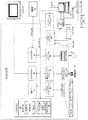
図1に示すように、汎用コンピューティングシステムは、処理ユニット21と、システムメモリ22と、システムメモリを含むシステムコンポーネントを処理ユニット21に連結するシステムバス23とを有した従来型のパーソナルコンピュータ20等を備える。システムバス23は、メモリバス又はメモリコントローラ、周辺バス、多様なバス構造のいずれかを使用するローカルバス等の幾つかある種類のバス構造のいずれかでよい。システムメモリは、リードオンリーメモリ(ROM)24とランダムアクセスメモリ(RAM)25を備える。基本入出力システム26(BIOS)は、パーソナルコンピュータ20の構成要素間で起動時に情報を転送するのに役立つ基本ルーティンを含み、ROM24に格納される。パーソナルコンピュータ20は、ハードディスク(図示なし)との間で読み書きを行うハードディスクドライブ27と、可動式磁気ディスク29との間で読み書きを行う磁気ディスクドライブと、CD ROM又は他の光メディア等の取り外し可能な光ディスク31との間で読み書きを行う光ディスクドライブ30とをさらに備える。ハードディスクドライブ27、磁気ディスクドライブ28および光ディスクドライブ30は、各々、ハードディスクドライブインタフェース32、磁気ディスクドライブインタフェース33、光ドライブインタフェース34に接続される。これらのドライブ及びこれらと関連するコンピュータ読み取り可能媒体は、パーソナルコンピュータ20のために、コンピュータ可読命令、データ構造、プログラムモジュール及びその他のデータの不揮発性記憶を提供する。本明細書に記載の環境例では、ハードディスク、可動式磁気ディスク29及び可動式光ディスク31が用いられているが、コンピュータからアクセス可能なデータを記憶できる他の種類のコンピュータ読み取り可能媒体、例えば、磁気カセット、フラッシュメモリカード、ディジタルビデオディスク、バーノウリカートリッジ(Bernouli cartridges)、ランダムアクセスメモリ(RAM)、リードオンリーメモリ(ROM)等をこのオペレーティング環境例で使用してもよいことを当業者は理解するはずである。
As shown in FIG. 1, a general-purpose computing system includes a conventional personal computer 20 having a processing unit 21, a
オペレーティングシステム35、1又は複数のアプリケーションプログラム36、その他のプログラムモジュール37及びプログラムデータ38を含む多数のプログラムモジュールをハードディスク、磁気ディスク29、光ディスク31、ROM.24、又は、RAM25に記憶させることができる。ユーザは、キーボード40、ポインティングデバイス42等の入力装置を介してパーソナルコンピュータ20にコマンド及び情報を入力できる。その他の入力装置(図示なし)は、マイクロホーン、ジョイスティック、ゲームパッド、サテライトディスク、スキャナー等を備えることができる。これらの入力装置及びその他の入力装置は、システムバスに連結したシリアルポートインタフェース46を介して処理ユニット21に接続されることが多いが、パラレルポート、ゲームポート又はユニバーサルシリアルバス(USB)等の他のインタフェースを介して接続されてもよい。モニター47又は他の種類の表示装置は、ビデオアダプター48等のインタフェースを介してシステムバス23に接続される。モニター47やパーソナルコンピュータは、通常、スピーカーやプリンター等の他の周辺出力装置(図示なし)を備える。図1のシステム例は、ホストアダプター55、スモール・コンピュータ・システム・インタフェース(SCSI)バス56及びSCSIバス56に接続された外部記憶装置62を備える。
A large number of program modules including an
パーソナルコンピュータ20は、リモートコンピュータ49等の1又は複数のリモートコンピュータとの論理的な接続を用いて、ネットワーク環境において動作することができる。リモートコンピュータ49は、別のパーソナルコンピュータ、サーバ、ルーター、ネットワークPC、ピアデバイス(peer device)、又は、他の共通のネットワークノードであってもよく、図1では1つの記憶装置50だけが示されているが、通常は、パーソナルコンピュータ20に関連する上述の構成要素の多くを又は全てを備える。図1に示した論理的な接続には、ローカルエリアネットワーク(LAN)51、広域ネットワーク(WAN)52が含まれる。このネットワーキング環境は、オフィス、企業規模のコンピュータネットワーク、イントラネット及びインターネットにおいては、一般的である。 The personal computer 20 can operate in a network environment using a logical connection with one or more remote computers such as the remote computer 49. The remote computer 49 may be another personal computer, server, router, network PC, peer device, or other common network node, and only one storage device 50 is shown in FIG. However, it typically includes many or all of the above-described components associated with the personal computer 20. The logical connection shown in FIG. 1 includes a local area network (LAN) 51 and a wide area network (WAN) 52. This networking environment is commonplace in offices, enterprise-wide computer networks, intranets and the Internet.
パーソナルコンピュータ20は、LANネットワーキング環境で使用される場合、ネットワークインタフェース又はアダプター53を介してLAN51に接続される。パーソナルコンピュータ20は、WANネットワーキング環境で使用される場合、通常、インターネット等の広域ネットワーク52上で通信を確立するためのモデム54又は他の手段を備える。モデム54は、内部にあっても外部にあってもよく、シリアルポートインタフェース46を介してシステムバス23に接続される。ネットワーク環境においては、パーソナルコンピュータ20と関連するプログラムモジュール又はそれらの一部をリモートメモリ記憶装置に記憶させることができる。図示されたネットワーク接続は例であり、コンピュータ間で通信リンクを確立する他の手段を用いてもよいことが理解されるであろう。本発明の多数の実施形態は、コンピュータ化されたシステムにとって特に適切であると想像されるが、本発明をその実施形態に限定させることを意図するものは本書類にはない。これに対して、コンピュータシステムという用語は、押しボタンを含む装置、又は、ボタン又はボタンの等価物が押されたことを判断できる装置のいずれか又はすべてを包含することを意図し、それらの装置が電気的、機械的、論理的、又は、仮想であるかどうかとは無関係である。
When used in a LAN networking environment, the personal computer 20 is connected to the
(ネットワーク環境)
図2は、本発明の態様を実施できるネットワーク環境の例を示す。実際のネットワークおよびデータベースの環境はいろいろな構成で配置され得る。しかしながら、ここで示す環境例は、本発明が動作する環境の種類を理解するためのフレームワークを示す。
(Network environment)
FIG. 2 illustrates an example network environment in which aspects of the invention may be implemented. The actual network and database environment can be deployed in a variety of configurations. However, the example environment shown here shows a framework for understanding the type of environment in which the present invention operates.
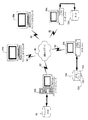
本ネットワークは、クライアントコンピュータ20a、サーバコンピュータ20b、データソースコンピュータ20c、データベース70、72a、72bを備える。クライアントコンピュータ20aとデータソースコンピュータ20cは、イントラネット等の通信ネットワーク80を介してサーバコンピュータ20bと電気的通信を行う。クライアントコンピュータ20aとデータソースコンピュータ20cは、通信インタフェース82を経由し通信ネットワークに接続される。通信インタフェース82は、イーサネット(登録商標)結合、モデム結合等の良く知られた通信インタフェースのどれかである。
The network includes a
サーバコンピュータ20bは、データベースサーバシステムソフトウェアを使ってデータベース70を管理するが、これについては詳しく後述する。したがって、サーバ20bは、多種類のデータソースから送られるデータの貯蔵庫としての役割を果たし、そのデータを多様なデータコンシューマに提供する。
The
図2の例では、データソースは、データソースコンピュータ20cによって提供される。データソースコンピュータ20cは、LAN、WAN、イントラネット、インターネット等の通信ネットワーク80を介してデータをサーバコンピュータ20bに通信する。データソースコンピュータ20cは、データベース72a、72bに局所的にデータを格納するが、これらのデータは、リレーショナルデータベースサーバ、エクセルスプレッドシート、ファイル等でよい。例えば、データベース72aは、テーブル150、152、154に保存されたデータを示す。データソース20cによって提供されるデータは、組み合わされて、サーバ20bによって整備されるデータ貯蔵庫等の大規模データベース内に保存される。サーバコンピュータ20bによって保存されるデータの使用を望むクライアントコンピュータ20aは、通信ネットワーク80を介してデータベース70にアクセスできる。クライアントコンピュータ20aは、SQLクエリー(例:更新、挿入、削除)を使って、データベース70に保存されているそのデータを要求する。
In the example of FIG. 2, the data source is provided by the data source
(概要)
本発明の一部の実施形態にとって“オブジェクト”は、限定せずに、ダイアログボックス、メニュー、ウェブページ、テキストページ、可動の図面オブジェクト、又は、当業者により知られ理解される、コンピュータシステムの他のアイテムとから構成される。本発明を説明するために、全てのオブジェクトを便宜的に4つのカテゴリーに分類可能と仮定する。4つのカテゴリーとは、(1)ユーザが複数の要素の中から1の要素を選択するための、ダイアログボックス、メニュー等の選択ボックス、(2)編集可能なテキストオブジェクト等のコンテンツオブジェクト、(3)可動図面オブジェクト(MDOs)、および、(4)オーディオオブジェクトである。実際には、もっと多くのカテゴリーが考えられ、かつ望まれるが、それらのカテゴリーを含めた場合、追加のオブジェクトグループの独自の特性に対応するために当業者に対して本明細書記載のロジックの拡張を単に要求するだけであるため、そのような拡張は本発明によって予期され開示されているとみなすべきである。
(Overview)
For some embodiments of the present invention, an “object” includes, but is not limited to, a dialog box, menu, web page, text page, movable drawing object, or other computer system known and understood by those skilled in the art. It is composed of items. For purposes of explaining the present invention, it is assumed that all objects can be classified into four categories for convenience. The four categories are (1) a selection box such as a dialog box or a menu for the user to select one element from a plurality of elements, (2) a content object such as an editable text object, (3 ) Movable drawing objects (MDOs), and (4) audio objects. In practice, more categories are conceivable and desired, but when those categories are included, the logic described herein can be used by those skilled in the art to accommodate the unique characteristics of additional object groups. Such extensions should be considered as anticipated and disclosed by the present invention because they merely require extensions.
入力デバイス上で、ボタンが押され、又は、(後述する)ホイール又はドッグボーン(dogbone)が転がされ又は回転し又はロックされたときはすぐに、基本的な物理的相互作用によって、本発明をともなう使用のための論理的入力を構成する適切な電気信号が生成される(そのよう論理的入力は、当業者によって広く知られ、理解されている。)。ボタン、ホイール、ドッグボーン以外の入力装置(例えば、音声認識入力、赤外線信号入力、パテント認識入力(patent recognition input)等があるが、これらに限定されない。) を用いた物理的相互作用によって生成される論理的入力は、本発明の各種実施形態をともなう使用に適するであろう。したがって、本明細書のいかなる事項も、論理的入力を本明細書に明示的に開示された装置グループに単に制限するために解釈すべきではない。しかし、便宜上、物理的相互作用のために役に立つ構成要素(例えば、ボタン)への言及は、各物理的相互作用によって生じる論理的入力への直接的な言及になるものとする。換言すると、ボタン、ホイール、ドッグボーン、または、他のそのような装置を含んだ入力装置の構成要素は、物理的に作用を受けた場合に、本明細書に記載された実施形態の論理的入力を構成するものとする。したがって、限定のない例として、「ENTER ボタン」は、「ENTERのための論理的入力」の1形態である。 As soon as a button is pressed on the input device, or a wheel or dogbone (described below) is rolled or rotated or locked, the present invention can be controlled by basic physical interaction. Appropriate electrical signals are generated that constitute the logical input for use with (such logical input is widely known and understood by those skilled in the art). Generated by physical interaction using input devices other than buttons, wheels, and dogbones (eg, but not limited to voice recognition input, infrared signal input, patent recognition input, etc.) Such logical inputs may be suitable for use with various embodiments of the present invention. Accordingly, nothing in this specification should be construed as merely limiting the logical input to the device groups explicitly disclosed herein. However, for convenience, references to components (eg, buttons) that are useful for physical interactions shall be direct references to the logical inputs generated by each physical interaction. In other words, the components of the input device, including buttons, wheels, dogbones, or other such devices, will be the logical ones of the embodiments described herein when physically acted upon. It shall constitute the input. Thus, as a non-limiting example, an “ENTER button” is a form of “logical input for ENTER”.
ユーザが直ちに識別でき、簡単かつ一貫性のある方法で情報をナビゲートするために使用するインタフェース装置の基礎を提供する主なボタン/ホイール/ドッグボーングループは、本発明の各種実施形態の中心に位置する。本実施形態は、一般的に最低限必要なコマンド(コアコマンド)のグループのための論理的ボタンのコアグループを備え、一部の実施形態は、ナビゲーションコマンド(補助的コマンド)の補助的セットに対する付加的な論理的ボタンを備える。論理的ボタンは、(後に詳細に定義され説明される)ホイール又はドッグボーンからの明白な入力イベントの個別ボタン又は論理的な等価物、又は、論理的ボタンの組み合わせを備え、各種実施形態によって利用されてコアコマンド及び補助的コマンドを作り出す。その他の実施形態においては、比較的少ない物理的構成要素を備えかなりの数の論理的ボタンを処理して、コアコマンドや補助的コマンドをはるかに超える驚異的なナビゲーショナル機能を実行できるが、当該機能は、場合によっては、オブジェクト、アプリケーション、又は、特定及び/又は変更可能な装置であり得る一般的コマンドを含んでもよい。 The main button / wheel / dogbone group that provides the basis for an interface device that can be readily identified by the user and used to navigate information in a simple and consistent manner is at the heart of various embodiments of the present invention. To position. This embodiment generally comprises a core group of logical buttons for a group of minimally required commands (core commands), some embodiments for an auxiliary set of navigation commands (auxiliary commands) With additional logical buttons. Logical buttons comprise individual buttons or logical equivalents of obvious input events from wheels or dogbones (defined and described in detail later), or combinations of logical buttons, utilized by various embodiments. To produce core commands and auxiliary commands. In other embodiments, it can handle a significant number of logical buttons with relatively few physical components to perform surprising navigational functions far beyond core and auxiliary commands, Functions may include general commands that may be objects, applications, or specific and / or changeable devices in some cases.
本発明の多くの実施の形態におけるコアコマンドは、おおよそ、Up、Down、Enter、Escapeのキーボードキーイベントと同等である。なぜなら、これらのコアコマンドは、スキャンニングや切り替えという2つの最も基本的なナビゲーションの機能 ―スキャンニングビューと選択、ビューの中で受諾すること又は拒否すること及び選択― と通常最も関連するコマンドコールであるからである。UpとDownの十字キーはスキャンのための唯一の方法ではない。しかし、メニュー、一覧表、スクローリングビューは、全て、垂直軸に沿って配列され、これらの2つのキー操作に常に反応するため、これらのキーは、この基本的なユーザ作業にとって最も十分に確立したものである。この関連性は、本発明におけるスキャンニング軸に関するユーザの概念モデルの基礎を形成する。同様に、Enterキーは、スクリーン(グラフィカルユーザーインタフェース又はGUI)上で目下選択されている機能をすべてアクティブにし又は実行する大変頼もしい手段として、ほとんど例外なく、コンピュータユーザに知られている。また、一般的に、Escapeは、意味的にはEnterと反対のものとみなされており、メールメッセージを閉じることやダイアログボックスを閉じること等の多くの共通的なバックアウトシナリオを取り扱う。しかし、本発明の多くの実施の形態の重要な態様は、ナビゲーションの機能が、ナビゲートされるコンテキストやアプリケーションオブジェクトに基づいて変わり得るということである。また、ナビゲーションの追加機能は、補助的コマンドによって実行される。 The core commands in many embodiments of the present invention are roughly equivalent to the Up, Down, Enter, and Escape keyboard key events. Because these core commands are usually the most relevant command calls with the two most basic navigation functions, scanning and switching-scanning view and selection, accepting or rejecting and selecting in a view- Because. The Up and Down cross keys are not the only way to scan. However, since menus, lists, and scrolling views are all arranged along the vertical axis and always respond to these two keystrokes, these keys are most well established for this basic user task. It is a thing. This relevance forms the basis of the user's conceptual model for the scanning axis in the present invention. Similarly, the Enter key is almost universally known to computer users as a very reliable means of activating or executing all currently selected functions on a screen (graphical user interface or GUI). Also, in general, Escape is semantically considered the opposite of Enter, and handles many common backout scenarios such as closing a mail message and closing a dialog box. However, an important aspect of many embodiments of the present invention is that the functionality of navigation can vary based on the context or application object being navigated. Further, the navigation additional function is executed by an auxiliary command.
Escape機能について言うと、本明細書に記載された発明の各種実施形態の別の重要な態様は、従来のEscape機能がデート(date)に適しているという事実があるにもかかわらず、長年にわたりEscape機能の実行は、本明細書に記載された発明の多くの実施形態のコアコマンドとしての役目を果たすことに実際には完全に制限される。例えば、アプリケーション内のウィンドウオブジェクトを閉じるさいに、大抵のウィンドウはEscapeキーには実際には反応せずに「Alt-F4」キーボードの打鍵に反応するだけであるということが広く理解されている。ナビゲーションの「履歴」― すなわち、ナビゲーションは、ナビゲーションの結果である何らかの論理的なパスに沿っており、ツリー構造データ又はその他のツリー構造オブジェクトである。― をそなえたアプリケーションについて言うと、ウィンドウを閉じる行為は、戻る(go Back)(すなわち、ビューイング履歴に基づいて、ウィンドウを開いたまま現在のコンテキスト内の前のコンテンツ又は異なるコンテンツに戻ること)ことの必要性及び欲求ほど重要でもなく、広く使用されてもいない。したがって、本発明の多数の実施形態においては、Escapeの概念を、OUTボタン用の一層パワフルな(後述の)「Out」に置き換える。とはいえ、その他の実施形態では、適宜、Escape又はBackをOUTにマッピングする。 Regarding the Escape function, another important aspect of the various embodiments of the invention described herein has been over the years despite the fact that the conventional Escape function is suitable for dates. The execution of the Escape function is actually completely limited to serve as a core command for many embodiments of the invention described herein. For example, when closing a window object in an application, it is widely understood that most windows do not actually respond to the Escape key, but only respond to keystrokes on the “Alt-F4” keyboard. Navigation “history” —that is, navigation is along some logical path that is the result of navigation, and is tree-structured data or other tree-structured objects. -For applications with-, the act of closing a window is go back (ie, returning to the previous content in the current context or different content with the window open based on the viewing history) It is not as important and widely used as the need and desire of things. Thus, in many embodiments of the present invention, the Escape concept is replaced by a more powerful “Out” (described below) for the OUT button. However, in other embodiments, Escape or Back is mapped to OUT as appropriate.
この原理に基づくと、本発明の各種実施形態は、コアナビゲーションコマンドを集合的に表すOUT、UP、DOWN、ENTERの4つの論理的ボタンを備えた装置向きである。主要な機能性グループは、補助的コマンドを利用する機能強化された多くの発明の実施形態の基礎をなす。基礎的なボタングループと、コアコマンドに対する対応の機能性とをユーザアプリケーションの絶え間のない変化に合わせることができる。例えば、4つの基礎的なナビゲーションボタンの機能又は「ナブボタン(navbuttons)」を、ワイヤレスディスプレイ、リモートコントロール、キーフォブ(key fobs)、腕時計、高度自動機能電話(smart phone)、音楽装置、その他のユーザアプリケーション等の多種多様な操作面に制限なく適用することができ、それらの装置が伝統的なコンピューティング装置と認められるかどうかを問わない。 Based on this principle, the various embodiments of the present invention are suitable for devices with four logical buttons, OUT, UP, DOWN and ENTER, which collectively represent core navigation commands. The main functionality group forms the basis of many enhanced embodiments of the invention that make use of auxiliary commands. The basic button group and the functionality of responding to core commands can be matched to the constant changes of the user application. For example, four basic navigation button functions or “navbuttons”, wireless display, remote control, key fobs, wrist watch, smart phone, music device, and other user applications Regardless of whether these devices are recognized as traditional computing devices.
ディスプレイモニター上で目に見える効果等の現実に目に見える結果を開示する実施形態にとっては、目に見えない効果もまた予測され、含まれる。例えば、1組のボタンが、ディスプレイ装置上でカーソルを上下に動かすものとして記載されている場合には、聞こえる効果(例えば、音量の上げ下げ)、触知性の効果(例えば、表面温度の上昇又は下降)等の、効果が目に見えない代替の実施形態が予測される。したがって、本明細書から目に見えない結果を十分に予測できるので、本明細書のいかなる事項についても、本発明の各種実施形態が視覚型の結果に限定されるように解釈すべきではない。 For embodiments that disclose real-visible results, such as visible effects on a display monitor, invisible effects are also predicted and included. For example, if a set of buttons is described as moving the cursor up and down on a display device, the audible effect (eg, volume up or down), tactile effect (eg, surface temperature rise or fall) Alternative embodiments where the effect is not visible are expected. Accordingly, invisible results from this specification can be sufficiently predicted, and nothing in this specification should be construed as limiting the various embodiments of the invention to visual results.
最後に、本明細書に開示された実施形態の多くは、スタンドアロン装置内にあるのが理想ではあるが、大型装置の一部として組み込まれても構わない。例えば、多くの実施形態は、限定なく、キーボード上の(おそらく、十字キーの集団とページングキーの集団の間の)ボタンの集団として、又は、(その他のボタンとインタフェースを加えた)ディスプレイと並んだボタンの集団として、又は、タッチスクリーン内の仮想のボタン(またはその他の仮想の実施形態)等として現れて構わない。いずれにせよ、本明細書のいかなる事項についても、本発明の態様がスタンドアロンの実施形態に限定されるように解釈すべきでない。 Finally, many of the embodiments disclosed herein are ideally in a stand-alone device, but may be incorporated as part of a larger device. For example, many embodiments include, without limitation, as a group of buttons (possibly between a group of cross keys and a group of paging keys) on a keyboard or alongside a display (plus other buttons and interfaces). It may appear as a group of buttons or as a virtual button (or other virtual embodiment) in a touch screen. In any event, nothing in this specification should be construed as limiting aspects of the invention to standalone embodiments.
(コアコマンド及び関連する実施形態)
以下のコマンドは、本明細書で用いられるキーコアコマンドの一部と、特定のコンテキスト内でのシステムによる解釈方法とからなる。
(Core commands and related embodiments)
The following commands consist of some of the key core commands used herein and how they are interpreted by the system within a specific context.
・ UP: 1のユニット、ライン、セル、スクロールインクリメント、ページ、又は、スクリーンを上に移動する(進める)こと;MS Windows APPCOMMAND_NAVPAD_UP イベント又は、USB HID NAVPAD_UP イベント
・ DOWN:1のユニット、ライン、セル、スクロールインクリメント、ページ、又は、スクリーンを下に移動する(進める)こと;MS Windows APPCOMMAND_NAVPAD_DOWN イベント、又は、USB HID イベント
・ NEXT:次のオブジェクト、フィールド、リンク、又は、ウィンドウ枠に移動する(スキップする)こと;MS Windows APPCOMMAND_NAVPAD_NEXT イベント、又は、USB HID NAVPAD_DOWN イベント
・ PREV:前のオブジェクト、フィールド、リンク、又は、ウィンドウ枠に移動する「(スキップする)こと;MS Windows APPCOMMAND_NAVPAD_PREV イベント、又は、USB HID NAVPAD_PREV イベント
・ ENTER:(キーボードのEnterキー又はその他のコンテキストのOKボタンに類似する)現在のオブジェクト上で操作する(実行する)こと;MS Windows APPCOMMAND_NAVPAD_ENTER イベント、又は、USB HID NAVPAD_ENTER イベント
・ CENTER:(キーボードのEnterキーに類似するが異なる)現在のオブジェクト上で操作する(実行する)こと;MS Windows APPCOMMAND_NAVPAD_CENTER イベント、又は、USB HID NAVPAD_CENTER イベント
・ OUT:前のオープンオブジェクト、ページ、又は、ビューに戻ること;(コンテキストに適切なものとして、Esc、Back、又は、本明細書の他のところに記載されている縦続Esc/Backの結合に類似する)起動中のオブジェクトを閉じること;MS Windows APPCOMMAND_NAVPAD_OUT イベント、又は、USB HID NAVPAD_OUT イベント
・ MORE:現在のオブジェクトに利用可能なオプションに関する詳細を表示すること、又は、そのオプションを実行すること;MS Windows APPCOMMAND_NAVPAD_MORE イベント、又は、USB HID NAVPAD_MORE イベント
・ SWITCH:次のウィンドウ、スクリーン、ページ、アプリケーション、又は、機能上の提供品に切り替えること;MS Windows APPCOMMAND_NAVPAD_SWITCH イベント、又は、USB HID NAVPAD_SWITCH イベント。
-UP: Move (advance) one unit, line, cell, scroll increment, page, or screen up; MS Windows APPCOMMAND_NAVPAD_UP event or USB HID NAVPAD_UP event-DOWN: one unit, line, cell, Scroll increment, move page or screen down (advance); MS Windows APPCOMMAND_NAVPAD_DOWN event or USB HID event • NEXT: move to next object, field, link, or window frame (skip) MS Windows APPCOMMAND_NAVPAD_NEXT event or USB HID NAVPAD_DOWN event • PREV: Move to the previous object, field, link, or window pane “(skip); MS Windows APPCOMMAND_NAVPAD_PREV event or USB HID NAVPAD_PREV event ENTER: (key Operate (execute) on the current object (similar to the board Enter key or other context OK buttons); MS Windows APPCOMMAND_NAVPAD_ENTER event or USB HID NAVPAD_ENTER event • CENTER: (similar to the keyboard Enter key) Manipulating (executing) on the current object; MS Windows APPCOMMAND_NAVPAD_CENTER event or USB HID NAVPAD_CENTER event • OUT: Returning to the previous open object, page, or view; Closing an active object (similar to a cascaded Esc / Back combination as described elsewhere in this document as Esc, Back, or as an MS Windows APPCOMMAND_NAVPAD_OUT event or USB HID NAVPAD_OUT event) MORE: Details about the options available for the current object Or execute that option; MS Windows APPCOMMAND_NAVPAD_MORE event or USB HID NAVPAD_MORE event • SWITCH: Switch to the next window, screen, page, application, or functional offering; MS Windows APPCOMMAND_NAVPAD_SWITCH Event or USB HID NAVPAD_SWITCH event.
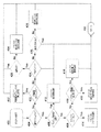
図3Aは、本発明の一実施形態におけるENTERボタンのロジックを示すフローチャートである。ブロック302において、ENTERボタンが押されると、ブロック304において、ENTERボタンシステムは、オブジェクトが選択オブジェクト(そして、コンテンツオブジェクト又は可動図面オブジェクトでないこと)であるか否かを判定し、否の場合、本実施形態ではその他のイベントは発生せず、ブロック350でシステムはリターンする(本発明のヌルイベント(null event)以外のイベントは、コンテンツオブジェクト及び可動図面オブジェクト対して必ず発生し、このことは当業者によって理解されるであろう。)。これに対して、オブジェクトが、実際に選択オブジェクトである場合には、ブロック306において、システムは、オブジェクト内の起動中の要素が既に選択されているか否かを判定する。起動中の要素が既に選択されている場合、ブロック312において、キーボードのEnterキーを押したのと同等な''execute''イベントが発生する(その結果は、必要に応じて、選択された要素のOpen、Accept、又は、OKとなり、これらのイベントは、当業者によって知られ理解される。)。ブロック350において、システムはリターンする。これに対して、起動中の要素が選択されていな場合、ブロック308において、システムは、オブジェクトの要素がイニシャルフォーカス(Initial Focus)(デフォルト選択要素)としてマークされているか否かに関して判定し、マークされている場合、ブロック314において、イニシャルフォーカスとしてマークされている要素が選択され、その後、ブロック350でシステムはリターンする。最後に、イニシャルフォーカスが無い場合、ブロック316において、システムは、最初に載ったオブジェクトの要素を選択し、ブロック350でリターンする。
FIG. 3A is a flowchart illustrating the logic of the ENTER button in one embodiment of the present invention. When the ENTER button is pressed at
当然ながら、図3Bのフローチャートへの変形が、ある状況のもとでは望まれるであろう。例えば、図3AのENTERボタンのロジックにおける変形を示すフローチャートである図3Bを検討する。この実施形態においては、(a)ブロック304において、オブジェクトが選択オブジェクトであるか否か、(b)ブロック306において、起動中の要素が選択されていないかどうか、(c)ブロック308において、オブジェクトがイニシャルフォーカスをもつか否かを(図3Aの方法と同一の方法で)判断した後に、ブロック310において、図3Bのシステムは、起動中の要素が目に見えるか否かを更に判断し、目に見える場合、ブロック318において、最初に目に見える要素を選択し、目に見えない場合、ブロック316において、最初に載った要素を選択する。本発明は、ロジック内のこの変形及びその他の微妙な変形を本明細書に開示する。
Of course, variations to the flowchart of FIG. 3B may be desirable under certain circumstances. For example, consider FIG. 3B, which is a flowchart showing a variation in the logic of the ENTER button of FIG. 3A. In this embodiment, (a) in
尚、これらの特有の実施形態の方法及び本明細書に書かれた他のものを用いることによって、(まだ一つも選択されていないとき)ユーザは、一回、ENTERボタンを押すことによって要素を選択することができ、ENTERボタンを再度押すことによって(キーボードのEnterキーを押すことと等価な)要素を実行することができる。 Note that by using the methods of these specific embodiments and others described herein, the user can select an element by pressing the ENTER button once (when none has been selected). The element can be selected and the element can be executed by pressing the ENTER button again (equivalent to pressing the Enter key on the keyboard).
図4Aは、本発明の一実施形態におけるUPボタンのロジックを示すフローチャートである。ブロック402において、UPボタンが押されると、ブロック404において、UPボタンシステムは、オブジェクトが選択オブジェクトであるか否かを判定する。選択オブジェクトでない場合、ブロック422において、システムは、オブジェクトがコンテンツオブジェクトか可動図面オブジェクトであるか否かを判断する。オブジェクトが可動図面オブジェクトである場合、ブロック432において、システムは、オブジェクトを所定の距離(例えば、1ピクセル)だけ押し上げ(上に動かし)、ここ(および図の他の個所)から推測できるように、その方向にさらに動かすことが不可能であるか又は許可されない場合には何もしない。所望の方向への動きが不可能であるか又は許可されていない場合のヌルイベントの処理するロジックが現段階では明らかにされていないが、そのロジックの例は、ハッシュラインブロック(hash-line blocks)によって図示され、コンテンツオブジェクトのために後半に説明される。そのロジックは、必要に応じて残りの図面に対して推定され暗示され得る。
FIG. 4A is a flowchart illustrating the UP button logic in one embodiment of the invention. When the UP button is pressed at
再び図面に戻ると、オブジェクトが実際にコンテンツオブジェクトである場合には、ブロック424において、システムは、オブジェクト内のテキストが1ライン又は複数ラインからなるか否かを判定する。テキストオブジェクトが複数ラインからなる場合、(所望の方向への移動が不可能であるか又は許可されていない場合にヌルイベントを処理するロジックを表すために)ブロック426において、システムは、挿入ポイントが、現在、最初のライン上にあるかどうかを判定し、もしある場合には、システムは何もせずに、ブロック450でリターンする。そうでなければ、ブロック434において、システムは、挿入ポイントを1ライン上に動かし、ブロック450でリターンする。逆に言えば、テキストオブジェクトが1ラインのみからなっている場合には、ブロック428において、システムは、現在、挿入ポイントがラインの最初の文字の前にあるかどうかを判定し、ある場合には、システムは、何もせずにブロック450でリターンする。そうでなければ、ブロック436において、システムは、挿入ポイントを1文字分左に動かし、ブロック450でリターンする。
Returning to the drawing again, if the object is actually a content object, at
ブロック404において、システムが、オブジェクトが選択オブジェクトと判断した場合、ブロック406において、システムは、オブジェクト内の要素が既に選択されているか否かを判定する。アクティブ要素が既に選択されている場合、ブロック412において、システムは、リスト内の前の要素を選択し(暗に、当該選択された前の要素は、選択されていない。)、システムはブロック450でリターンする。これに対して、アクティブ要素が選択されていない場合、ブロック408において、システムは、オブジェクトの要素が(デフォルト選択要素として)イニシャルフォーカスとしてマークされているか否かに関して判定し、そうである場合には、ブロック414において、イニシャルフォーカスとしてマークされている要素を選択し、その後、システムはブロック450でリターンする。最後に、イニシャルフォーカスがない場合には、ブロック416において、システムは、オブジェクトの最初に載った要素を選択し、ブロック450でリターンする。
If, at
図4Bは、図3Bと図3Aを区別するために明細書の中で先立って紹介したものと類似する変形に基づいた、図4AのUPボタンのロジックの変形を示すフローチャートである。図4Bの実施形態において、---再度、(a)ブロック404において、オブジェクトが選択オブジェクトであるか否か、(b)ブロック406において、アクティブ要素が選択されていないかどうか、(c)ブロック408において、オブジェクトがイニシャルフォーカス(図4Aの方法と同一)でないかどうか、を(図4Aの方法と同一な方法で)判定した後に、---ブロック410において、図4Bのシステムは、アクティブ要素が目に見えるか否かをさらに判定し、見える場合には、ブロック418において、最初に目に見える要素を選択し、見えない場合には、ブロック416において、システムは最初に載った要素を選択する。
FIG. 4B is a flowchart illustrating a variation of the UP button logic of FIG. 4A based on a variation similar to that introduced earlier in the specification to distinguish FIGS. 3B and 3A. In the embodiment of FIG. 4B, again, (a) whether the object is a selected object in
図5Aは、本発明の一実施形態におけるDOWNボタンのロジックを示すフローチャートである。ブロック502において、DOWNボタンが押されると、ブロック504において、DOWNボタンシステムは、オブジェクトが選択オブジェクトであるか否かを判断する。選択オブジェクトでない場合、ブロック522において、システムは、オブジェクトがコンテンツオブジェクト又は可動図面オブジェクトであるか否かを判定する。オブジェクトが可動図面オブジェクトである場合、ブロック532において、システムは、オブジェクトを、所定の距離(例えば、1ピクセル)、単に、少しずつ押す(動かす)か、又は、ここ(又は、図面のその他の箇所)から推測できるように、その方向にさらに動かすことができないか、許可されていない場合、なにも行わない。これに対して、オブジェクトがコンテンツオブジェクトである場合には、ブロック524において、システムは、オブジェクト内のテキストが1行又は複数行から成るか否かを判断する。テキストオブジェクトが複数行から成る場合には、ブロック526において、システムは、挿入ポイントが現在、最終行にあるか否かをさらに判定し、そうである場合には、システムは何もせずにブロック550でリターンする。そうでない場合には、ブロック534において、システムは、挿入ポイントを1行下に移動し、ブロック550でリターンする。反対に、テキストオブジェクトがちょうど一行から成る場合には、ブロック528において、システムは、挿入ポイントが、現在、行の最終文字の後ろにあるか否かを判断し、そうである場合には、システムは何もせずにブロック550でリターンする。そうでない場合には、ブロック536において、システムは、挿入ポイントを1文字右に移動し、ブロック550でリターンする。
FIG. 5A is a flowchart illustrating the logic of the DOWN button in one embodiment of the present invention. When the DOWN button is pressed at
ブロック504において、システムが、オブジェクトが選択オブジェクトであると判定した場合、ブロック506において、システムは、オブジェクト内のアクティブ要素が既に選択されているか否かを判定する。アクティブ要素が既に選択されている場合には、ブロック512において、システムは、リスト内の次の要素を選択し(暗に、当該前に選択された要素は、選択されていない。)、システムはブロック550でリターンする。これに対して、アクティブ要素が選択されていない場合、ブロック508において、システムは、オブジェクトの要素がイニシャルフォーカスとして(デフォルト選択要素として)マークされているか否かに関して判定し、そうである場合には、ブロック514において、イニシャルフォーカスとしてマークされている要素を選択し、その後、システムは550でリターンする。最後に、イニシャルフォーカスがない場合には、ブロック516において、システムは、オブジェクトの最後に載った要素を選択して、ブロック550でリターンする。
If at
図5Bは、図3Bと図3A、図4Bと図4Aを区別するために明細書の中で先立って紹介したものと類似する変形に基づいた、図5AのDOWNボタンのロジックの変形を示すフローチャートである。図5Bの実施形態において、---再度、(a)ブロック504において、オブジェクトが選択オブジェクトであるか否か、(b)ブロック506において、アクティブ要素が選択されていないかどうか、(c)ブロック508において、オブジェクトがイニシャルフォーカスでないこと、を(図5Aの方法と同一な方法で)判断した後に、---ブロック510において、図5Bのシステムは、アクティブ要素が目に見えるかどうかをさらに判断し、見える場合には、ブロック518において、最後に目に見える要素を選択し、見えない場合には、ブロック516において、システムは最後に載った要素を選択する。
FIG. 5B is a flow chart illustrating a variation of the logic of the DOWN button of FIG. 5A based on a variation similar to that previously introduced in the specification to distinguish FIGS. 3B and 3A and FIGS. 4B and 4A. It is. In the embodiment of FIG. 5B, again, (a) whether the object is a selected object in
従来のEscape機能は、長い間使用されているという事実があるにもかかわらず、それは、やはり、かなり制限され非常に特殊化されている。例えば、ウィンドウを閉じるために、大抵のウィンドウは、実際には、Escapeキーには全く反応せずに、代わりに''Alt-F4''キー入力に反応するだけである。ナビゲーション“履歴”を有するアプリケーションに関して言うと、― すなわち、ナビゲーションがある種の論理的パスに沿っている場合 ― ウィンドウを閉じる行為は、戻る(go Back)(すなわち、ウィンドウを開いたままにすること及びビューイング履歴に基づいて、現在のコンテンツ内の前のコンテンツ又は異なるコンテンツに戻ること)ことの必要性及び欲求ほど重要ではない(また、広く使用されてもいない。)。したがって、OUTボタンに関して言うと、本発明の一実施形態のために、Escape又はBackの概念を一層パワフルな''Out''の概念に置き換える。 Despite the fact that the traditional Escape feature has been used for a long time, it is still quite limited and very specialized. For example, to close a window, most windows do not actually respond to the Escape key at all, but instead respond to the "Alt-F4" keystroke. As far as applications with navigation “history” are concerned—that is, when navigation follows a certain logical path—the act of closing a window is a go back (ie, leaving the window open). And the need and desire to return to previous content in the current content or to different content based on viewing history (and not widely used). Thus, when referring to the OUT button, we replace the Escape or Back concept with the more powerful “Out” concept for one embodiment of the present invention.
実施形態を重ね合わせると、OUTを、BackコマンドコールとEscapeコマンドコールとが提供する機能を論理的かつうまく対処された組み合わせにすることできる。すべてのウィンドウがEscapeに応答するオペレーティングシステムにおいては、これら2つのボタンを融合することは非常に有益である。なぜならば、これらのキーを様々なアプリケーションコンテクストの中で十分かつ一貫して使用することがめったにないからである。BackとEscapeのどちらも利用し、各々に区別できる機能をもたせた少数のアプリケーションにおいては、OUTボタンがどのキーボードキーに複製されるかをユーザに推測させるのは現実的ではなく、非能率である。本発明の一実施形態によって提供される1つの解決策は、当のアプリケーションがBackキーコマンドを理解するとき、OUTボタンを使用してBackキーコマンドを生成すること、および、アプリケーションがBack キーコマンドを理解しないとき、かわりに、Escapeキーコマンドを生成すること、― すなわち、Escapeコマンドを付随させたBackコマンドを縦続させることである。この方式では、履歴を有するアプリケーションは、---Backに移動できることがEscapeを介してウィンドウを閉じることよりも頻繁にあり、また、より重要である場合等---- Backキー機能のより大きな利点を得、一方、Backキー機能を有さないアプリケーションは、Escapeキーによって得られる機能であれば何でも自動的に得る。Back/Escapeキー選択のこの方法論を、OUTボタンを介して実行するために、本発明の一実施形態は、最初にオペレーティングシステムのシェルフックを用いて、「App コマンド」(アプリケーションプログラムへのアプリケーションコマンド)として、Backキーを生成し、次に、Backコマンドがアプリケーションによって拒否される場合には、キーボードのEscapeキーを押すのと等価なEscapeコマンドを生成する。その他の実施形態では、適宜、Escape又はBackを単純にOUTにマッピングできる。本明細書には、OUTの基本的な機能を制限することを意図することは何も含まれていない。それでもなお、本明細書においては、OUTはBack/Escapeの縦続機能を指すと仮定する。 Overlapping the embodiments, OUT can be a logical and well-coordinated combination of the functions provided by the Back and Escape command calls. In an operating system where all windows respond to Escape, fusing these two buttons is very beneficial. This is because these keys are rarely used sufficiently and consistently in various application contexts. In a few applications that use both Back and Escape, each with a distinct feature, it is impractical and inefficient to let the user guess which keyboard key the OUT button will be duplicated on . One solution provided by one embodiment of the present invention is that when the application understands the Back key command, it uses the OUT button to generate the Back key command, and the application receives the Back key command. If you don't understand, instead, generate an Escape key command--that is, cascade a Back command accompanied by an Escape command. In this way, applications with history can be moved to --- back more frequently than closing windows via Escape, etc. On the other hand, an application that does not have the Back key function will automatically get whatever function is provided by the Escape key. In order to perform this methodology of Back / Escape key selection via the OUT button, one embodiment of the present invention first uses an operating system shell hook to create an “App command” (application command to an application program). ), A Back key is generated, and if the Back command is rejected by the application, an Escape command equivalent to pressing the Escape key on the keyboard is generated. In other embodiments, Escape or Back can simply be mapped to OUT as appropriate. This document does not include anything intended to limit the basic functionality of OUT. Nevertheless, it is assumed herein that OUT refers to the Back / Escape cascade function.
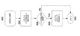
図6Aは、本発明の一実施形態におけるOUTボタンの方法のロジックを示すフローチャートである。ブロック602において、OUTボタンが押されると、ブロック604において、OUTボタンシステムは、オペレーティングシステムのシェルフックを用いて、(時々、Browser Backキー又はその他の等価物としてラベルがつけられ、その操作は、時々、マウスの右クリックとして実行される)キーボードのBackキーをユーザが押すことによって生成されるコマンドと等価なアプリケーションコマンドをアプリケーションに発行する。次に、ブロック606において、システムは、Backアプリケーションコマンドが拒否されたか否かを判断し、拒否されない場合、システムはブロック650でリターンし、そうでなければ、ブロック608において、システムはEscapeコマンドを発行し、ブロック650でリターンする。
FIG. 6A is a flowchart illustrating the logic of the OUT button method in one embodiment of the invention. When the OUT button is pressed at
図6Bは、図6Aに示された方法論に基づいたOUT.ボタンの方法のより複雑なロジックを示すフローチャートである。図6Bでは、ブロック602において、OUTボタンが押されると、ブロック610において、システムは最初に、ウィンドウが、その履歴の始めにあるかどうかを確かめる(したがって、どこにも戻らない。)。そのケースにおいては、方法は、次の2つのことの1つを行い得る。(a)それは、OUTボタン(ヌルイベント)を無視し、すぐに戻る。できたら、(b)それは、Escapeを介してウィンドウを閉じる。後者の選択肢を実行するためには、次の2つの方法のうちの1つを用いる可能性がある。(i)システムは、Backコマンドを送る手続きをとり、(戻り先がないため)このアプリケーションコマンドがアプリケーションによって拒否されると推定される場合、システムは、(図6Aで示された方法論である)Escapeコマンドを送る手続きをとり、又は、(ii)システムは、すぐにEscapeコマンドを送る可能性がある。このことは、本図面に示されている。したがって、ブロック610において、ウィンドウがその履歴の始めにあるとシステムが判断した場合、システムはすぐにブロック608の手続きをとり、Escapeコマンドを発行し、ブロック650でリターンする。そうでない場合、ブロック604において、システムは、オペレーティングシステムのシェルフックを再び用いて、Backのためのアプリケーションコマンドをアプリケーションに発行し、次に、ブロック606において、Backアプリケーションコマンドが拒否されたか否かを判定し、拒否されない場合には、ブロック650でリターンし、そうでない場合には、ブロック608において、Escapeコマンドを発行し、ブロック650でリターンする。
6B is a flowchart illustrating more complex logic of the OUT. Button method based on the methodology illustrated in FIG. 6A. In FIG. 6B, when the OUT button is pressed at
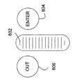
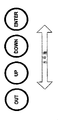
本発明の様々な物理的実施形態が考えられる。図7Aに示された1実施形態は、例えば、パッド又はデバイスの上にひし形で配置されたENTER 702、OUT 704、UP 706、DOWN 708のボタンを備える4つのボタンの配置である。図7Bは、本発明の代替実施形態であり、それは、例えばコンピューティング装置の右端に沿って垂直方向に配置された4つのボタンを備える点を除いて類似の幾何学的配置を有する。図7Cは、例えばコンピューティング装置の先端に沿って水平方向に配置されたボタンを示す本発明の別の代替実施形態である。これに対して、図7Dは、本発明のさらにもう一つの実施形態であり、それは、中心にENTER 702を備え、ENTER702の上下に垂直に各々UP706とDOWN708を備え、3つの直線的に配置されたボタンの左上部にOUT704を備える改良垂直方式によって配置されたボタンを示す。当然ながら、色々なコマンドの組み合わせを4ボタン装置に割り当てることができるかもしれない。図7Eの装置は、4つのボタンがコマンドUP、DOWN、PREV、NEXTに対応する点を除いて、図7Aの装置と類似する装置を示す。
Various physical embodiments of the present invention are contemplated. One embodiment shown in FIG. 7A is an arrangement of four buttons comprising, for example, ENTER 702,
しかしながら、本明細書に開示された4ボタンスキーマは、論理的なものであって、物理的なものではないため、本発明の一部の実施形態は異なる物理的構成要素を利用することもできる。例えば、図8Aに示された本発明の一実施形態は、1つの垂直ホイール802と2つのボタン804と806を備えたホイール/ボタンの組み合わせからなり、そこでは、ホイール802は、ホイールが(図示されたように、上又は下に)向けられた方向に基づいたUPとDOWNの両機能と論理的に同等とみなされ、一方、ボタン804とボタン806は、それらが押されたときに、各々、ENTERとOUTと相互に関連がある。この実施形態のホイール802は、本技術分野においてよく知られ理解されているように、マウス装置のホイールと類似の方式で動作し、上又は下へのわずかな転がりが入力をなす。図8Bは、ホイール/ボタンの組み合わせの一実施形態の別のレイアウトを示し、図8Cは、実施形態のさらに別のレイアウトを示す。
However, because the 4-button schema disclosed herein is logical and not physical, some embodiments of the present invention may utilize different physical components. . For example, one embodiment of the invention shown in FIG. 8A consists of a wheel / button combination with one
図9は、本発明の別の代替実施形態を示し、そこでは、ホイール902は、UPとDOWNに対応する上下運動をサポートするばかりでなく、所定の最小スレシホールドの圧力が加えられると、ENTERのボタンとして動作する。この圧力入力の特長によって、本明細書ではクリッキングホイールとして参照されるホイール902は、3つの異なる入力を受け付けることができ、一方、4番目の入力であるOUTは、クリッキングホイール902に近接したボタン904に対応する。
FIG. 9 illustrates another alternative embodiment of the present invention in which the
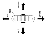
本発明の別の実施形態においては、図10に示すように、4ボタンスキーマは、単一の物理的要素であるロッキングホイールによって用いられる。ロッキングホイール1002は、垂直方向の回転動作と妥協することなしにサイドトーサイド(side-to-side)のロッキング機構を更にサポートする。この機能により、右へのロッキングは、ENTERと関連があり、左へのロッキングは、OUTと関連があり、一方、UPとDOWNは、(図に示した通り)ホイール1002の上下の転がりによって得られ続ける。また、本実施形態のために示されたロッキングホイールに図9のクリッキングホイールの圧力入力をさらに組み込んだ場合、その実施形態は、第5のボタン機能を得、その第5のボタン機能を、後で詳細に論じられる一部の興味深い実施形態を提供する5+ボタン構成の一部で使用できるかもしれない。
In another embodiment of the present invention, as shown in FIG. 10, a four button schema is used by a single physical element, the locking wheel. The
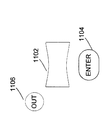
図11Aは、図8Aに開示された発明と類似する本発明の別の実施形態を示し、従来のホイールの代わりに、ドックボーン(dogbone)1102を利用する。ドックボーン1102は、本来、人間工学的に改良されたホイールデバイスであり、従来のホイールが人差し指による使用に比較的適しているのに対して、ドッグボーンは、親指による関与に特に適している。本実施形態においては、ドックボーン1102が垂直に上又は下に転がる動作は、(図に示された通り)論理的には、各々、UPとDOWNの両機能と同等とみなされ、一方、ボタン1104と1106が押されると、それらは、各々、ENTERとOUTと相互に関連がある。図11Bは、ドックボーン/ボタンを組み合わせた実施形態の別のレイアウトを示し、図11Cは、実施形態のさらにもう一つのレイアウトを示す。
FIG. 11A shows another embodiment of the present invention that is similar to the invention disclosed in FIG. 8A, utilizing a
図12は、本発明の別の代替実施形態を示し、そこでは、ドックボーン1202は、UPとDOWNに対応する上下運動をサポートするばかりでなく、所定の最小スレシホールドの圧力が加えられると、ENTERのボタンとして動作する。この圧力入力の特長により、本明細書ではクリッキングドックボーンとして参照されているドックボーン1202は、3つの異なる入力を受け付けることができ、一方、4番目の入力であるOUTは、クリッキングドッグボーン1202に近接したボタン1202に対応する。
FIG. 12 illustrates another alternative embodiment of the present invention in which the
最後に、図13に示した本発明の別の実施形態において、4−ボタンのスキーマは、単一な物理的要素、すなわち、ロッキングドッグボーン1302によって用いられる。ロッキングボーン1302は、垂直方向の回転動作と妥協することなしにサイドトーサイドのロッキング機構を更にサポートすることによって、図10に示されたロッキングホイール1002と類似する。この機能を備えることよって、ドッグボーン1302を左にロッキングすることは、ENTERと相互に関連があり、ドッグボーン1302を右にロッキングすることは、OUTと相互に関連があり、一方、UPとDOWNは、(図に示した通り)ドッグボーン1302の上下の転がりから得られ続ける。また、本実施形態のために示されたロッキングドッグボーンに図12のクリッキングドッグボーンの圧力入力をさらに組み込んだ場合には、その実施形態は、第5のボタン機能を得、その第5のボタン機能を、後で詳細に論じられる一部の興味深い実施形態を提供する5+ボタン構成の一部で使用できるかもしれない。
Finally, in another embodiment of the invention shown in FIG. 13, a 4-button schema is used by a single physical element, namely the
(拡張コマンドと、関連実施形態)
本明細書でこれまで開示してきた本発明の実施形態は、4つの基本コマンドであるENTER、UP、DOWN、OUTに直接マッピングされる4つボタン(又は、ホイールやドッグボーンの場合にはボタンと論理的に等価なもの)を備えるスキームに焦点を合わしている。オブジェクトをナビゲーションするための最も有益なコマンドを備える単純なスキーマの能力を否定はしないが、物理的に、時間的に、論理的に、組み合わせ的といった4つの方法の内の1つの方法でボタンの機能を拡張することによって、より広い範囲の機能が有効となる。例えば、一部の実施形態が4つの基本コマンドであるENTER、UP、DOWN、OUTとは別にマッピングするかもしれない追加のコマンドは、6−論理的ボタンの実施形態のために、PREVとNEXTを備え、8−論理的ボタンの実施形態のために、PREV、NEXT、MORE、SWITCHを備える。
(Extended commands and related embodiments)
The embodiments of the present invention disclosed so far in this specification include four buttons (or buttons in the case of wheels and dogbones) that map directly to the four basic commands ENTER, UP, DOWN, and OUT. Focuses on schemes with logical equivalents). It does not deny the ability of a simple schema with the most useful commands for navigating objects, but it can be used in one of four ways: physically, temporally, logically, combinatorially. By expanding the functions, a wider range of functions become effective. For example, additional commands that some embodiments may map separately from the four basic commands ENTER, UP, DOWN, and OUT are PREV and NEXT for 6-logical button embodiments. Equipped with PREV, NEXT, MORE, SWITCH for the 8-logical button embodiment.
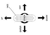
論理的な4−コマンド配列を拡張する1つの方法は、単純に、より多くのボタン(又は、ボタンと論理的に等価なもの)を追加し、追加のコマンドをマッピングすることによって、物理的な4−ボタンの配置を拡張することである。例えば、図10に示されたロッキングホイールの4−ボタン機能が、図9のクリッキングフィールドの圧力入力機能を備える場合、この機能強化されたホイール(以下、スーパーホイールと称する。)は、論理的に第5のボタンを明らかにし、第5のコマンドを直接使用する(または、本明細書で後述するように、論理的に又は組み合わせのスキーマで利用される)。同様に、図12に示されたロッキングドッグボーンの4−ボタン機能が、図13のクリッキングホイールの圧力入力機能をさらに備える場合、この機能強化されたドッグボーン(以下、スーパードッグボーンと称する。)は、論理的に第5のボタンを明らかにし、第5のコマンドを直接使用することができる(または、再び、本明細書で後述するように、論理的に又は組み合わせのスキーマで利用される)。図14Aは、スーパーホイールを利用する本発明の一実施形態を示し、一方、図14Bは、スーパードッグボーンを利用する本発明の一実施形態を示す。 One way to extend the logical 4-command array is to simply add more buttons (or logical equivalents of buttons) and map additional commands to the physical 4- Expand the button layout. For example, if the 4-button function of the locking wheel shown in FIG. 10 includes the pressure input function of the clicking field of FIG. 9, this enhanced wheel (hereinafter referred to as the super wheel) is logically. Reveal the fifth button and use the fifth command directly (or be used in a logical or combinational schema as described later in this document). Similarly, when the 4-button function of the rocking dog bone shown in FIG. 12 further includes the pressure input function of the clicking wheel of FIG. 13, this enhanced dog bone (hereinafter referred to as a super dog bone). Can logically reveal the fifth button and use the fifth command directly (or again, as used later in this document, logically or in a combined schema) . FIG. 14A illustrates one embodiment of the present invention that utilizes a super wheel, while FIG. 14B illustrates one embodiment of the present invention that utilizes a super dogbone.
スーパーホイールまたはスーパードッグボーンを追加のボタンと組み合わせた場合、片手で(又は、1本の指又は親指でも)操作可能なパワフルなナビゲーション装置が生じる。例えば、一部の実施形態においては、装置は、ロッキングボタンに2つのボタンを加えて使用し(全部で6つの論理的ボタン)、又は、ロッキングボタンに4つのボタンを加えて使用(全部で8つの論理的ボタン)する可能性があり、各々に対応するコマンドが論理的ボタンにマッピングされる。同様に、これらの実施形態の各々において、ロッキングドッグボーンの代わりにスーパードッグボーンを用いることによって、各々、7−ボタン装置又は9−ボタン装置が得られる。 Combining a super wheel or super dog bone with an additional button results in a powerful navigation device that can be operated with one hand (or even with one finger or thumb). For example, in some embodiments, the device uses two buttons on the locking button (6 logical buttons in total) or uses 4 buttons on the locking button (8 in total). Two logical buttons), and corresponding commands are mapped to logical buttons. Similarly, in each of these embodiments, a 7-button device or 9-button device, respectively, is obtained by using a super dogbone instead of a rocking dogbone.
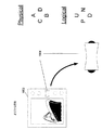
図15Aは、スーパードッグボーンと、配列の中心にあるスーパードッグボーンとともに垂直方向に配置される4つの追加の物理ボタンを利用するナビゲーション装置の一実施形態を示す。この9−ボタン装置を、以後、ナイナー(niner)と称し、一方、図15Aに示される9−ボタン装置は、垂直ナイナーと称するものとする。図15Aを参照すると、垂直ナイナー1502は、上側に2つのボタン1506とボタン1508を付け、下側に2つのボタン1510とボタン1512を付けたスーパードッグボーン1504を備える。各ボタンに対する直接コマンド(又は、論理入力)は、図15Cの表にリストアップされている。尚、この実施形態においては、ENTER、UP、DOWN、OUTの機能は、本明細書で既に開示している機能と同じであり、ENTERコマンドは(要求はされないが、許可されている)2つの論理的ボタンに対応する。同様に、別の実施形態は、図15Bに示された8−ボタン装置を備え、ENTERが単一の論理的ボタンのみに対応する点を除いて、類似のコマンドマッピングを有する。尚、TabとAlt-Tabコマンドコールに対応するPREVとNEXTは、Left ArrowとRight Arrow機能の代わりに実行される。その理由は、ナビゲーションのコンテキストの中では、PREVとNEXTの機能は、比較的役に立つからである。とは言っても、ある状況においては、例えば、OUTコマンドにおけるEscapeとBackの組み合わせと類似する方法でPREVとLeft Arrowコマンドを一緒に結合することが望ましい。
FIG. 15A illustrates one embodiment of a navigation device that utilizes a super dog bone and four additional physical buttons arranged vertically with the super dog bone in the center of the array. This 9-button device will hereinafter be referred to as a “niner”, while the 9-button device shown in FIG. 15A shall be referred to as a vertical nineer. Referring to FIG. 15A, the
論理的ボタンの機能を拡張する別の方法は、ボタンが押されて、所定の時間、「押さえつけられる」(''held down'')ときに、特別な機能を提供することである。例えば、ユーザがUPボタンを押し、押さえつけた場合には、本発明のある実施形態にとって、それを異なるコマンド、例えば、キーボードのPage Upキーを複製するPAGEUPコマンドとして解釈することは論理的であろう。代わりに、システムは、自動的に、素早くUPコマンドを繰り返すこともあり得、このことは、キーボードのUp Arrowキーを押して、押さえつけることの効果と類似する。 Another way to extend the functionality of a logical button is to provide a special function when the button is pressed and "" held down "for a predetermined time. For example, if the user pressed and pressed the UP button, it would be logical for some embodiments of the invention to interpret it as a different command, for example, a PAGEUP command that duplicates the keyboard's Page Up key. . Instead, the system may automatically repeat the UP command quickly, which is similar to the effect of pressing and pressing the Up Arrow key on the keyboard.
本明細書に記載されたボタンスキーマの機能を拡張する別の方法は、異なる種類の「動き」(motion)を見分けることであり、これは、マウスがシングルクリックとダブルクリックとを区別する方法と類似する。例えば、ホイール又はドッグボーンのスキーマを利用するとき、ホイールの上又は下のフリック(flick)(短時間内の大きな動作であるフリック)を別個の論理的ボタンとみなすことは論理的拡張であろう。例えば、ドッグボーンを上又は下に正常回転させると、結果としてUP又はDOWNとなるのに対して、ホイールを上又は下にフリックは、PAGEUP又はPAGEDOWNコマンドを捕らえ得、それらはキーボードのPage Up、Page Downキーと各々一致する。 Another way to extend the functionality of the button schema described herein is to distinguish different types of “motion” from the way the mouse distinguishes between single clicks and double clicks. Similar. For example, when using a wheel or dogbone schema, it would be a logical extension to consider the flick above or below the wheel (a flick that is a large action in a short time) as a separate logical button. . For example, normal rotation of the dogbone up or down will result in UP or DOWN, while flicking the wheel up or down may catch a PAGEUP or PAGEDOWN command, which will cause the keyboard Page Up, Matches with Page Down key.
ボタンの機能を拡張する別の強力な手段は、同時に押されたときに、個々のボタンと通常関連付けられたコマンドとは異なるコマンドを表すために使用されるボタンの様々な組み合わせを考慮することである。例えば、本発明の一実施形態は、主要なナビゲーション論理的ボタングループとして、4つの物理的ナビゲーションボタン、ロッキングドッグボーン、又は、ロッキングホイールとを備え、さらに、おそらく4つの論理的ボタンに2次的なマッピングをもたせることを可能とする変更ボタンをおそらく備える。変更ボタンは、ラップトップ、タブレットPC等の多くのコンピュータ装置の'Fn'キーと多くの点で等価であろう。さらに、変更するもの(modifier)は、特別なコンピュータ装置にとって特に有用な特別メニューを呼び出す等の追加コマンドを実行する「ダブルタップ」(double-tapped)であり得る。特別メニューは、例えば、装置において縦方向と横方向の相互間で表示を回転させるメニューであり、その装置では、その機能が特に関連があり有用である。これについては、以下に詳細に説明する。 Another powerful means of extending the functionality of a button is to consider the various combinations of buttons used to represent different commands than those normally associated with individual buttons when pressed simultaneously. is there. For example, one embodiment of the present invention comprises four physical navigation buttons, a locking dogbone, or a locking wheel as the main navigation logical button group, and possibly secondary to the four logical buttons. Perhaps with a change button that allows you to have a different mapping. The change button would be equivalent in many respects to the 'Fn' key on many computing devices such as laptops, tablet PCs and the like. Further, the modifier can be a “double-tapped” that performs additional commands such as invoking a special menu that is particularly useful for special computer devices. The special menu is, for example, a menu for rotating the display between the vertical direction and the horizontal direction in the apparatus, and the function is particularly relevant and useful in the apparatus. This will be described in detail below.
これまで記述した実施形態は、所与のコンテキスト内の様々な物理的ユーザ対話に基づいて様々な論理的結果をマッピングすることに大きく基礎をおいている。しかしながら、別の実施形態によって、単一の特別な物理的対話が様々なコンテキスト内(テキストドキュメント、仮想ブック、又は、スライドショー等)の様々な論理的結果(ステップ、スクロール、又は、ページ等)を生じさせることを可能にするであろう。例えば、ロッキングドッグボーンを用いてのローリングダウン(rolling down)は、コンテキスト内で、1行、ステッピングダウンすること、別のコンテキスト内で、1ページ、スクローリングダウンすること、および、さらに別のコンテキスト内で、1ドキュメント、ページングダウンすることと同等とみなされ、各コンテキスト内で対応する反対の論理結果を有するローリングアップ(rolling up)を有する。同様に、再びロッキングドッグボーンを用いてのロッキングレフト(rocking left)は、1コンテキスト内でウィンドウ枠間を飛び越え、別のコンテキスト内でリンクの間をスキップし、又は、さらに別のコンテキスト内のツリー型の階層の低いブランチに入ることができ、各コンテキスト内で対応する反対の論理結果を有するローリングダウンを有する。その他の実施形態は、ロッキングホイール、スーパードッグボーン、スーパーホイール、ひし形構成の4ボタン、32方位に似た円に沿って均等に構成された8ボタン、ジョイスティック、D-パッド、タッチパッド、タッチストリップ等を用いて同様に機能する方針に従っている。その他のコマンドは、ステップ、スクロール、ページとは別に、コマンドに対抗するその他の2アブストラクト(一般的に「アブストラクト」)のみならず、(「アクセス」(access)と共に)ENTERとOUTを含むことができる。 The embodiments described so far are largely based on mapping different logical results based on different physical user interactions within a given context. However, according to another embodiment, a single special physical interaction can produce different logical results (steps, scrolls, pages, etc.) within different contexts (such as text documents, virtual books, or slide shows). It will be possible to make it happen. For example, rolling down with a rocking dogbone can be one line in a context, stepping down, one page in another context, scrolling down, and yet another context Within one context, it is considered equivalent to paging down and has a rolling up with a corresponding opposite logical result within each context. Similarly, a rocking left with a rocking dogbone again skips between panes in one context, skips between links in another context, or a tree in another context It can enter the lower branch of the type hierarchy and has a rolling down with a corresponding opposite logical result within each context. Other embodiments include rocking wheel, super dogbone, super wheel, diamond shaped 4 buttons, 8 buttons equally configured along a circle resembling 32 orientations, joystick, D-pad, touch pad, touch strip Etc. are followed in the same functioning policy. Other commands may include ENTER and OUT (along with "access") as well as two other abstracts (generally "abstract") to combat the command, apart from steps, scrolls and pages. it can.
(柔軟性に富んだ方向付け)
縦方向と横方向の間で表示を回転させるメニューが特に関連があり有用である装置において、様々な実施形態に組み込まれた本発明の別の重要な要素は、論理的ボタンコマンドを物理ボタンに再設定する能力である。例えば、その右側にロッキングボーン1604を取り付けた「右手用の縦」方向(''right-handed portrait '' orientation)の状態のタブレットPC等の表示装置を示す図16Aの装置を考えてみる。便宜上、ロッキングドッグボーン1604の各論理的ボタンの機能、すなわち、ローリングアップ、ローリングダウン、ロッキングレフト、ロッキングライトの各論理的ボタンの機能は、各々、A、B、C、Dと名付けられ、ロッキングドッグボーン1604に対して一貫性を持ち続けている。これに対して、UP、DOWN、PREV、NEXTコマンドについてのU、D、P、Nとラベル付けされた、ロッキングドッグボーン1604の各論理的ボタンに対するコマンドは、実際には、この特別な物理的方向(すなわち、右手用の縦方向)でのロッキングドッグボーン1604と関連があり、また、論理的ボタンをコマンドに論理的マッピングすることは、以下の通りに表すことができる(左にラベル、右にコマンド)
(Flexible orientation)
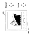
In devices where menus that rotate the display between portrait and landscape are particularly relevant and useful, another important element of the present invention incorporated into various embodiments is that logical button commands are converted to physical buttons. Ability to reset. For example, consider the device of FIG. 16A showing a display device such as a tablet PC in a “right-handed portrait” orientation with a
A=U
B=D
C=P
D=N
A = U
B = D
C = P
D = N
しかしながら、本発明の一部の実施形態に関しては、ディスプレイ装置1602が回転すると、論理的ボタンの割り当ては的確に再マッピングされる。例えば、90度(1/4)右に「下側横方向」(''bottom landscape'' orientation)に回転した後の装置1602を示す図16Bを考える。このことは、ユーザが装置に対して表示の向きを変えるように指示した後に生じると考えられる。論理的ボタンへのコマンドの再マッピングが自動的に引き続いて生じる。この回転された方向においては、ロッキングドッグボーン1604への論理的マッピングは以下の通りに表すことができる(左にラベル、右にコマンド)。
However, for some embodiments of the present invention, when the
A=D
B=U
C=P
D=N
A = D
B = U
C = P
D = N
尚、論理的ボタンAとBに対するコマンドが入れ替わっている(即ち、UPコマンドとDOWNコマンドが入れ替わっている)のに対して、論理的ボタンCとDに対するコマンドは同じままである。その理由としては、ドッグボーン1604は、実際は、当初は垂直方向に方向づけて示されている1つの軸に沿って転がるだけであるからである。その軸は、望ましくは表示の垂直方向にマッピングされるべきであり、その理由は、垂直方向の表示動作は、一般的には、水平方向の表示動作よりも重要であり、かつ、より頻繁に利用されるからである。したがって、ドッグボーン1604の転がりの能力は、常に、垂直方向の動作に論理的にマッピングされるべきであり、この場合において、右への転がり動作を表示の下方向移動と一致させることは自然である(また、少なくとも、その他の方向付け及びテキスト文書の読み方と調和がとれている)。同様に、この場合において、ロッキングアップを表示の左方向移動と一致させるロッキングの再マッピングは、自然である(また、少なくとも、その他の方向付け及びテキスト文書の読み方と調和がとれている)。論理的ボタンと、論理的ボタンが呼び出すコマンドとの論理的関係を再マッピング(実際には、部分的な再マッピング)することによって、ユーザは、装置の方向を変えることができ、方向の変化と大いに両立する方法でユーザーインタフェースを利用することができる。
Note that commands for logical buttons A and B are interchanged (ie, UP and DOWN commands are interchanged), while commands for logical buttons C and D remain the same. This is because the
図16Cは、右にさらに90度回転させた同じ装置(全部で180度又は右に1/2)及び、この装置の方向で見られるように自動又は手動で新しい方向による表示がなされたときに生じる再マッピングの説明図である。この方向においては、ロッキングドッグボーン1604の論理的マッピングは以下のように表すことができる(左にラベル、右にコマンド)。
FIG. 16C shows the same device rotated further 90 degrees to the right (180 degrees in total or 1/2 to the right) and when displayed automatically or manually with the new direction as seen in the direction of this device. It is explanatory drawing of the resulting remapping. In this direction, the logical mapping of the
A=D
B=U
C=N
D=P
A = D
B = U
C = N
D = P
この方向、すなわち、「左利き用の縦」方向(''left-handed portrait'' orientation)は、特に、左利きのユーザにとって有用である。尚、前回の方向と比較すると、論理的ボタンCとDのコマンドは入れ替わっているのに対して、論理的ボタンAとBのコマンドは同じままである。この再マッピング(180度)は、実際には、前回の方向からの部分的な再マッピング(右に90度)にすぎないが、最初の方向からは完全に再マッピングされている。 This orientation, the “left-handed portrait” orientation, is particularly useful for left-handed users. Compared to the previous direction, the commands for logical buttons C and D are interchanged, while the commands for logical buttons A and B remain the same. This remapping (180 degrees) is actually only a partial remapping (90 degrees to the right) from the previous direction, but is completely remapped from the first direction.
図16Dは、右にさらに90度回転(全部で270度又は右に3/4)させ、「上側横」方向(''top landscape'' orientation)を形成する同じ装置であり、この装置の方向で見られるように自動又は手動で新しい方向による表示がなされたときに再マッピングが結果として生じる。この方向においては、ロッキングドッグボーン1604の論理的マッピングは以下のように表すことができる(左にラベル、右にコマンド)。
FIG. 16D shows the same device rotated 90 degrees to the right (total 270 degrees or 3/4 to the right) to form the “top landscape” orientation. Remapping results when a new orientation is displayed either automatically or manually as seen in FIG. In this direction, the logical mapping of the
A=U
B=D
C=N
D=P
A = U
B = D
C = N
D = P
尚、前回の方向と比較すると、論理的ボタンCとDは同じままであるのに対して、論理的ボタンAとBは入れ替わっている。装置がもう一回回転し最初の位置に戻ったと仮定すると、論理的ボタンAとBのコマンドは同じままであるのに対して、論理的ボタンCとDは入れ替わっている。要するに、本発明の一部の実施形態は、固定のナビゲーション装置の論理回転スキームを使用することにより、論理的ボタンが、それらの方向に依存した特別のコマンドに対応する。その正確なマッピングを図17の表に示す。このマッピングは、ホイールやドッグボーンを備えた場合等の、1つの物理軸に沿って左右対称な装置に最も適している。 Compared with the previous direction, logical buttons C and D remain the same, whereas logical buttons A and B are interchanged. Assuming that the device has been rotated one more time and returned to its initial position, the commands of logical buttons A and B remain the same, while logical buttons C and D are interchanged. In summary, some embodiments of the present invention use a fixed navigation device logical rotation scheme so that logical buttons correspond to special commands that depend on their orientation. The exact mapping is shown in the table of FIG. This mapping is best suited for devices that are symmetrical along one physical axis, such as with wheels or dogbones.
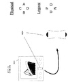
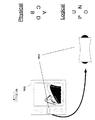
図18Aは、別の表示装置1802、すなわち、限定しない例として、装置の底部にロッキングドッグボーン1804を組み込んだ「フロントエンド長手」方向のポケット型表示装置を示し、この装置は、1/4ずつ右に3回連続回転し、図16A-Dに示された装置と類似の方式で論理コマンドを再マッピングする。
FIG. 18A shows another
回転表示装置のジレンマの別の解決策は、物理的ユーザーインタフェース自体を回転させることである。図19Aは、回転可能なナビゲーション装置1904を備えた表示装置1902を示し、この表示装置は、右手用縦方向を有する。図19Bは、回転可能なナビゲーション装置1904が表示装置1902の視野から90度右に回転し同じ絶対的な方向を保ちながら、右に90度回転した表示装置1902を示す。図19Cと図19Dは、さらに90度ずつ回転した同じ装置を示す。各々の場合において、ナビゲーション装置1904は、同じ絶対的な方向を保つ。
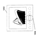
Another solution for the rotating display dilemma is to rotate the physical user interface itself. FIG. 19A shows a
類似する方法においては、回転したときに物理的に区別がつかないナビゲーショナル装置にとってローテンションは仮想的であり、論理的な回転だけを起こす必要がある。この方法論は、主要な回転軸を備えるホイール又はドッグボーンを利用するナビゲーショナル装置には適していないが、ボタンがひし形に配置されている図7Aの4ボタンナビゲーショナル装置等のその他の実施形態は、図19A−Dに開示された装置等の回転可能なナビゲーショナル装置を備えた表示装置のために実現される機能に類似する、回転装置で実現された機能を、物理的ボタンの間の簡易な直接再マッピング(論理的回転)に与える。物理的ボタン間のコマンドの回転は、既に説明したひし形の配置を備えたケース等、垂直及び水平の両方向で対称なナビゲーショナル装置によく適している。 In a similar manner, rotation is virtual for navigational devices that are not physically distinguishable when rotated, and only need to cause logical rotation. Although this methodology is not suitable for navigational devices that utilize wheels or dogbones with a primary axis of rotation, other embodiments such as the 4-button navigational device of FIG. Similar to the function implemented for a display device with a rotatable navigational device, such as the device disclosed in FIGS. 19A-D, the functions implemented on the rotating device are simplified between physical buttons. To direct remapping (logical rotation). The rotation of commands between physical buttons is well suited for navigational devices that are symmetrical in both the vertical and horizontal directions, such as the case with the rhombus arrangement already described.
(次元と無関係なナビゲーション)
これまでに記述した多くの実施形態において、および、特に左右対称の複数のボタンを備えたこれらの実施形態において、論理的ボタンの機能は、そのボタンの物理的位置に対応している。すなわち、論理的次元は物理的次元を示す。しかしながら、本発明の別の実施形態は、ユーザーインタフェース装置の機能をさらに拡張するために物理的次元と論理的次元の間の関係を壊す。
(Navigation independent of dimensions)
In many embodiments described so far, and particularly in those embodiments with a plurality of symmetrical buttons, the function of the logical button corresponds to the physical position of the button. That is, the logical dimension indicates the physical dimension. However, another embodiment of the present invention breaks the relationship between the physical and logical dimensions to further extend the functionality of the user interface device.
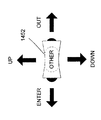
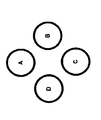
左右対称の複数のボタンは、(装置の論理的ボタンの全てを含んでも含まなくてもよい)論理的ボタンとそれらと物理的に等価なもの(プッシュボタン、ホイール又はドッグボーン)との組み合わせであり、後者は多次元方法で装置上に物理的に配置され、ボタンの機能が論理的に相互関係をもち物理的レイアウトから確定されることを意味する。例えば、異なる物理的構成で配置された4つのボタンからなる図20Aと図20Bを考える。これらの実施形態はどちらも同じボタンを有しているが、図20Aのボタンは2つの軸に沿って多次元的に配置される(UPとDOWNは垂直に配置され、一方、LEFTとRIGHTは水平に配置される。)。これに対して、図20Bのボタンは、単一の水平軸に沿って1次元的に配置される。図20Aの各ボタンの機能は、物理的レイアウトに結果であるが、ボタン間の相互関係によって示される。しかしながら、図20Bのボタン機能は不確定である。例えば、図20Cのボタンレイアウトに関しては、明確なラベルがない点を除いて図20Aのレイアウトと似ているが、これらのボタンの各々の機能は、相互に関係があると自然に推定でき(AとCは反対の関係で、BとDは反対の関係で、前者は垂直軸に関連するのに対して後者は水平軸に関連する。)、さらに、各ボタンと関係のある方向への動作に対応する。しかしながら、図20Dのボタンレイアウトは、明確なラベルがない点を除いて図20Bのレイアウトと似ているが、相互関係の示唆又は機能が2次元(垂直と水平)の動きと関連があるという示唆を与えない。 Symmetric buttons are a combination of logical buttons (which may or may not include all of the device's logical buttons) and their physical equivalents (push buttons, wheels or dogbones). Yes, the latter means that they are physically arranged on the device in a multidimensional manner, and the button functions are logically interrelated and determined from the physical layout. For example, consider FIGS. 20A and 20B, which consist of four buttons arranged in different physical configurations. Both of these embodiments have the same buttons, but the buttons in FIG. 20A are multi-dimensionally arranged along two axes (UP and DOWN are arranged vertically, while LEFT and RIGHT are Placed horizontally.) In contrast, the buttons of FIG. 20B are arranged one-dimensionally along a single horizontal axis. The function of each button in FIG. 20A is a result of the physical layout, but is indicated by the interrelationship between the buttons. However, the button function of FIG. 20B is indeterminate. For example, the button layout of FIG. 20C is similar to the layout of FIG. 20A except that there is no clear label, but the function of each of these buttons can be naturally estimated to be related to each other (A And C are in the opposite relationship, B and D are in the opposite relationship, the former is related to the vertical axis while the latter is related to the horizontal axis.) In addition, the movement in the direction related to each button Corresponding to However, the button layout of FIG. 20D is similar to the layout of FIG. 20B, except that there is no clear label, but the suggestion of interrelationship or function is related to two-dimensional (vertical and horizontal) movement. Not give.
確かに、図20A及び図20Cの4ボタン“ひし形”配置及びこれらと等価のもの(例えば、ロッキングホイールとロッキングドッグボーンを含む。)は水平軸及び垂直軸に沿った多次元動作を強力に示唆するため、この機能は自動的に推測されることが多い。その上、(水平及び垂直の配置等の)ボタン間の物理的関係は、これらのボタンに内在する(水平及び垂直の動き等の)機能に対応すると容易に推測される。また、(X、Y及び軸及び様々な対角線との関係で)空間内の多次元動作を自動的に推測させる多次元性を有する従来の技術は、分かりにくい。例えば、図21Aの“コンパス”ボタン配置を考える。この配置は、類似する図21Bと図21Cの配置によって明白に示されるように、ラベルがなくても、2次元空間内の4つの軸に沿った方向と関連があると自然に推測させる。しかしながら、多くのユーザナビゲーションコンテキストにおいては、単にボタンの物理的関係に基づいて相互に関係付けられた機能は、例えば、垂直動作は重要であるが、水平動作は重要でないとき、および、その逆のときには、最大限の効率を発揮しないかもしれない。 Indeed, the 4-button “diamond” arrangement of FIGS. 20A and 20C and equivalents (eg, including a locking wheel and a locking dogbone) strongly suggests multidimensional motion along the horizontal and vertical axes. Therefore, this function is often automatically inferred. In addition, the physical relationship between buttons (such as horizontal and vertical placement) is easily inferred to correspond to the functions (such as horizontal and vertical movement) inherent in these buttons. Also, conventional techniques with multidimensionality that automatically infer multidimensional motion in space (in relation to X, Y and axes and various diagonals) are difficult to understand. For example, consider the “compass” button arrangement of FIG. 21A. This arrangement is naturally inferred to be associated with directions along four axes in a two-dimensional space, even without labels, as clearly shown by the similar arrangements of FIGS. 21B and 21C. However, in many user navigation contexts, functions that are related to each other simply based on the physical relationship of the buttons, for example, when vertical motion is important but horizontal motion is not important, and vice versa. Sometimes it may not be as efficient as possible.
多様なコンテキストでのシングルユーザーインタフェース装置の汎用性及び適用性を最大にするために、本発明の別の実施形態は、非対称的(対称的でない)に関連付けられた(すなわち、論理的には互いに無関係)論理的ボタンに対応する(物理的には互いに関連している)左右対称の複数ボタンから成る。例えば図7Aの配置等の4ボタン多次元配置の本発明の一実施形態においては、垂直ボタンは垂直動作と対応するが、水平ボタンは、水平動作以外のこと(この場合は、ENTERとOUT)と対応する。同様に、本発明の別の実施形態においては、水平ボタンは水平動作と対応し、垂直ボタンは垂直動作以外のことと対応する。さらにもう一つの実施形態においては、水平ボタンは、水平動作以外のことと対応し、垂直ボタンは、垂直動作以外のことと対応する。この方法を使う別の実施形態は、多様な対称の複数性を備え、それは、制限はなく、4ボタンダひし形配置、8ボタンコンパス配置、(スーパードッグボーンと)ロッキングボーン、(スーパーホイールと)ロッキングホイール、D-Pad、ジョイスティック、様々なボタン配置、及び/又は、前述のもの及びそれらと等価なものの組み合わせを含む。さらに、本方法は、2次元の物理的又は論理的な実施形態に限定されず、物理的要素と論理的機能に関する真の多次元性を備える。 In order to maximize the versatility and applicability of a single user interface device in various contexts, another embodiment of the present invention is associated asymmetrically (not symmetrically) (ie, logically relative to each other). It consists of multiple symmetrical buttons that correspond to (unrelated) logical buttons (physically related to each other). For example, in one embodiment of the present invention with a 4-button multi-dimensional arrangement, such as the arrangement of FIG. And corresponding. Similarly, in another embodiment of the present invention, a horizontal button corresponds to a horizontal action and a vertical button corresponds to something other than a vertical action. In yet another embodiment, the horizontal button corresponds to something other than a horizontal action, and the vertical button corresponds to something other than a vertical action. Another embodiment using this method comprises a variety of symmetric pluralities, including, without limitation, a 4-button rhombus arrangement, an 8-button compass arrangement, a (super dogbone) and a locking bone (with a superwheel) locking Includes wheels, D-Pads, joysticks, various button arrangements, and / or combinations of the foregoing and their equivalents. Furthermore, the method is not limited to two-dimensional physical or logical embodiments, but provides true multidimensionality with respect to physical elements and logical functions.
(結論)
本明細書に記載された様々な技術は、ハードウェア又はソフトウェア、あるいは、それらを適宜組み合わせることによって実行される。したがって、本発明の方法及び装置、又は、そのいくつかの態様又は部分は、フロッピー(登録商標)ディスケット、CD-ROM、ハードドライブ、その他の機械により読み出しが可能な記憶媒体等の有形の媒体内で具現化されるプログラム(命令等)という形をとり、そこで、プログラムコードがコンピュータ等の機械に格納され、実行されると、その機械は、本発明を実行する装置になる。プログラム可能なコンピュータ上でプログラムコードが実行される場合には、コンピュータは、一般的に、プロセッサ、プロセッサによって読むことができる記憶媒体(揮発性メモリ及び不揮発性メモリ及び/又は記憶要素)、すくなくとも一つの入力装置、少なくとも一つの出力装置を含む。1又は複数のプログラムは、望ましくは、高レベルの手続き型のプログラム言語又はオブジェクト指向のプログラム言語で実行され、コンピュータシステムと通信を行う。しかしながら、プログラムは、必要ならば、アセンブリ又は機械語で実行される。いずれにせよ、言語は、コンパイル又はインタプリットされ、ハードウェア実装と結合する。
(Conclusion)
Various techniques described in this specification are executed by hardware or software, or a combination thereof. Accordingly, the method and apparatus of the present invention, or some aspects or portions thereof, are contained within a tangible medium such as a floppy diskette, CD-ROM, hard drive, or other machine-readable storage medium. When the program code is stored and executed in a machine such as a computer, the machine becomes a device for executing the present invention. When the program code is executed on a programmable computer, the computer typically has a processor, a storage medium (volatile and non-volatile memory and / or storage elements) readable by the processor, at least one. One input device and at least one output device. The one or more programs are preferably executed in a high level procedural programming language or object oriented programming language to communicate with the computer system. However, the program is executed in assembly or machine language, if necessary. In any case, the language is compiled or interpreted and combined with the hardware implementation.
本発明の方法と装置は、いくつかの伝送媒体、例えば、電気配線又はケーブル線上、又は光ファイバーを通して、又は、その他の伝送形式等で伝送され、そこで、EPROM、ゲートアレイ、プログラマブルロジックデバイス(PLD)、クライアントコンピュータ、ビデオレコーダ等の機械がプログラムコードを受信し、格納し、実行すると、機械は、本発明を実行する装置になる。プログラムコードが汎用プロセッサに実装されると、プログラムコードは、プロセッサと結合して、本発明のインデキシング機能を達成するために機能する独自の装置を提供する。 The method and apparatus of the present invention may be transmitted over several transmission media, eg, electrical wiring or cable lines, through optical fibers, or in other transmission formats, where EPROM, gate array, programmable logic device (PLD) When a machine such as a client computer, video recorder, etc. receives, stores and executes the program code, the machine becomes a device for carrying out the present invention. When program code is implemented in a general-purpose processor, the program code combines with the processor to provide a unique apparatus that functions to achieve the indexing functionality of the present invention.
本発明を、各種図面の実施形態と関連させて説明したが、その他の類似の実施形態が使用でき、又、本発明の機能と同じ機能を達成するために、ここから逸脱することなく、記述された実施形態に対して変更又は追加を加えることがでる。例えば、本発明の一実施形態は、パーソナルコンピュータの機能をエミュレートするディジタルデバイスのコンテキストで記述されるが、当業者であれば、本発明がそのディジタルデバイスに限定されないことを認識するであろう。また本発明をゲーム機、ハンドヘルドコンピュータ、ポータブルコンピュータ、モバイルフォーン、時計、音楽プレーヤー、特定の機械的装置等の現存又は新生のコンピュータ装置又はコンピュータ環境に適用することができ、有線であろうと無線であろうと、通信ネットワークを介して接続され又はネットワークを横切って相互に作用し合うコンピュータ装置にも適用することができる。さらに、例えば、“ボタン”(そして、本明細書において使用されているその他の物理的装置)は、特定の人間工学的な効果を上げるために、大きさ、形、間隔等を変えることができる。同様に、各ボタンは、単語、シンボルでラベル付けがされているか、又は、まったラベル付けがされず、また、ボタンに、異なるカラー、形、その他の特徴をつけることにより、区別する(又は区別しない)。 Although the present invention has been described in connection with embodiments of the various drawings, other similar embodiments can be used and described without departing from the present invention in order to achieve the same function as the present invention. Changes or additions can be made to the described embodiments. For example, although one embodiment of the invention is described in the context of a digital device that emulates the functionality of a personal computer, those skilled in the art will recognize that the invention is not limited to that digital device. . The invention can also be applied to existing or emerging computer devices or computer environments such as game consoles, handheld computers, portable computers, mobile phones, watches, music players, certain mechanical devices, etc., whether wired or wireless. Regardless, it can also be applied to computer devices that are connected via a communication network or interacting across the network. In addition, for example, “buttons” (and other physical devices used herein) can vary in size, shape, spacing, etc., to enhance certain ergonomic effects. . Similarly, each button is labeled with a word, symbol, or not labeled, and is distinguished by giving the button a different color, shape, or other feature (or Do not distinguish).
特にワイヤレスネットワーク装置の数が増大し続けているため、ハンドヘルドデバイスオペレーティングシステムやその他のアプリケーション固有のオペレーティングシステムを含む様々なコンピュータプラットホームが本明細書では意図されることを強調しなければならない。したがって、本発明は、単一の実施形態に限定されるべきではなく、添付の特許請求の範囲に基づいた広さ及び範囲で構築されるべきである。 It should be emphasized that a variety of computer platforms including handheld device operating systems and other application specific operating systems are contemplated herein, particularly as the number of wireless network devices continues to increase. Accordingly, the present invention should not be limited to a single embodiment, but should be construed in breadth and scope based on the appended claims.
Claims (44)
第1のコンテキストにおいて第1のコマンドを発行する前記論理的ボタンと、
第2のコンテキストにおいて第2のコマンドを発行する前記論理的ボタンと
を備えることを特徴とする方法。 In a method for extending the functionality of a navigational device comprising at least one logical button,
The logical button issuing a first command in a first context;
And a logical button for issuing a second command in a second context.
前記論理的ボタンが第1のコンテキストにおいて第1のコマンドを発行するための手段と、
前記論理的ボタンが第2のコンテキストにおいて第2のコマンドを発行するための手段と
を備えることを特徴とするハードウェア制御装置。 In a hardware control device comprising at least one logical button that issues a command when pressed,
Means for the logical button to issue a first command in a first context;
A hardware control device, wherein the logical button comprises means for issuing a second command in a second context.
ボタンが押下以外の所定の方法で使用される場合、代用コマンドを論理的ボタンにマッピングするステップと、
論理的ボタンが押下以外の所定の方法で使用される場合、代用コマンドを発行するステップと
を含むことを特徴とする方法。 In a method for extending the functionality of a navigational control device comprising at least one logical button that issues a command when pressed,
Mapping a substitute command to a logical button if the button is used in a predetermined manner other than pressing;
Issuing a substitute command if the logical button is used in a predetermined manner other than pressing.
論理的ボタンが転がり以外の所定の方法で使用される場合、代用コマンドを論理的ボタンにマッピングするステップと、
論理的ボタンが転がり以外の所定の方法で使用される場合、代用コマンドを発行するステップと
を含むことを特徴とする方法。 In a method for extending the functionality of a navigational control device comprising at least one logical button for issuing commands when used by rolling,
Mapping a substitution command to a logical button if the logical button is used in a predetermined manner other than rolling; and
Issuing a substitute command if the logical button is used in a predetermined manner other than rolling.
論理的ボタンがロッキング以外の所定の方法で使用される場合、代用コマンドを論理的ボタンにマッピングするステップと、
論理的ボタンがロッキング以外の所定の方法で使用される場合、代用コマンドを発行するステップと
を含むことを特徴とする方法。 In a method for extending the functionality of a navigational control device comprising at least one logical button that issues commands when used by locking,
Mapping a substitute command to a logical button if the logical button is used in a predetermined manner other than locking;
Issuing a substitute command if the logical button is used in a predetermined manner other than locking.
ボタンが押下以外の所定の方法で使用される場合に代用コマンドを論理的ボタンにマッピングするステップと、
論理的ボタンが押下以外の所定の方法で使用される場合に代用コマンドを発行するステップと
を含むことを特徴とするシステム。 In a system for performing a method for extending the functionality of a navigational control device comprising at least one logical button that issues a command when used by pressing,
Mapping a substitute command to a logical button when the button is used in a predetermined manner other than pressing;
Issuing a substitute command when the logical button is used in a predetermined manner other than pressing.
論理的ボタンが転がり以外の所定の方法で使用される場合に論理的ボタンに代用コマンドをマッピングするステップと、
論理的ボタンが転がり以外の所定の方法で使用される場合に代用コマンドを発行するステップと
を含むことを特徴とするシステム。 In a system for performing a method for extending the functionality of a navigational control device comprising at least one logical button for issuing commands when used by rolling,
Mapping a substitution command to the logical button when the logical button is used in a predetermined manner other than rolling;
Issuing a substitute command when the logical button is used in a predetermined manner other than rolling.
論理的ボタンがロッキング以外の所定の方法で使用される場合に代用コマンドを論理的ボタンにマッピングするステップと、
論理的ボタンがロッキング以外の所定の方法で使用される場合に代用コマンドを発行するステップと
を含むことを特徴とするシステム。 In a system for performing a method for extending the functionality of a navigational control device comprising at least one logical button that issues a command when used by locking,
Mapping a substitute command to a logical button when the logical button is used in a predetermined manner other than locking;
Issuing a substitute command when the logical button is used in a predetermined manner other than locking.
ボタンが押下以外の所定の方法で使用される場合に代用コマンドを論理的ボタンにマッピングするステップと、
論理的ボタンが押下以外の所定の方法で使用される場合に代用コマンドを発行するステップと
を備えることを特徴とするコンピュータ可読媒体。 In a computer readable medium having computer readable instructions for a method of extending the functionality of a navigational control device comprising at least one logical button that issues a command when used by pressing, the method comprises:
Mapping a substitute command to a logical button when the button is used in a predetermined manner other than pressing;
Issuing a substitute command when the logical button is used in a predetermined manner other than pressing, a computer readable medium comprising:
論理的ボタンが転がり以外の所定の方法で使用される場合に、代用コマンドを論理的ボタンにマッピングするステップと、
論理的ボタンが転がり以外の所定の方法で使用される場合に、代用コマンドを発行するステップと
を含むことを特徴とするコンピュータ可読媒体。 In a computer readable medium having computer readable instructions for a method for extending the functionality of a navigational control device comprising at least one logical button for issuing commands when used by rolling, the method comprises:
Mapping a substitute command to a logical button when the logical button is used in a predetermined manner other than rolling;
Issuing a substitute command when the logical button is used in a predetermined manner other than rolling.
論理的ボタンがロッキング以外の所定の方法で使用される場合に、代用コマンドを論理的ボタンにマッピングするステップと、
論理的ボタンがロッキング以外の所定の方法で使用される場合に、代用コマンドを発行するステップと
を含むこと特徴とするコンピュータ可読媒体。 In a computer readable medium having computer readable instructions for a method of extending the functionality of a navigational control device comprising at least one logical button that issues commands when used by locking, the method comprises:
Mapping a substitute command to a logical button when the logical button is used in a predetermined manner other than locking;
Issuing a surrogate command when the logical button is used in a predetermined manner other than locking.
ボタンが押下以外の所定の方法で使用される場合に代用コマンドを論理的ボタンにマッピングするステップと、
論理的ボタンが押下以外の所定の方法で使用される場合に代用コマンドを発行するステップと
を含むことを特徴とするハードウェア制御装置。 In a hardware controller for a method for extending the functionality of a navigational controller comprising at least one logical button that issues a command when used by pressing, said method comprising:
Mapping a substitute command to a logical button when the button is used in a predetermined manner other than pressing;
Issuing a substitute command when the logical button is used in a predetermined method other than pressing, a hardware control device comprising:
ボタンが押下以外の所定の方法で使用される場合に代用コマンドを論理的ボタンにマッピングする手段と、
論理的ボタンが押下以外の方法で使用される場合に代用コマンドを発行する手段と
を備えることを特徴とするハードウェア制御装置。 In a hardware control device comprising at least one logical button for issuing a command when used by pressing,
Means for mapping a substitute command to a logical button when the button is used in a predetermined manner other than pressing;
A hardware control device comprising means for issuing a substitute command when a logical button is used by a method other than pressing.
論理的ボタンが転がり以外の所定の方法で使用される場合に代用コマンドを論理的ボタンにマッピングするステップと、
論理的ボタンが転がり以外の所定の方法で使用される場合に代用コマンドを発行するステップと
を含むこと特徴とするハードウェア制御装置。 In a hardware controller for a method for extending the functionality of a navigational controller comprising at least one logical button for issuing commands when used by rolling, said method comprises:
Mapping a substitution command to a logical button when the logical button is used in a predetermined manner other than rolling;
Issuing a substitute command when the logical button is used in a predetermined method other than rolling.
論理的ボタンが転がり以外の所定の方法で使用される場合に代用コマンドを論理的ボタンにマッピングする手段と、
論理的ボタンが転がり以外の所定の方法で使用される場合に代用コマンドを発行する手段と
を備えることを特徴とするハードウェア制御装置。 In a hardware controller comprising at least one logical button for issuing a command when used by rolling,
Means for mapping a substitute command to a logical button when the logical button is used in a predetermined manner other than rolling;
A hardware control device comprising means for issuing a substitute command when the logical button is used in a predetermined method other than rolling.
論理的ボタンがロッキング以外の所定の方法で使用される場合に代用コマンドを論理的ボタンにマッピングするステップと、
論理的ボタンロッキング以外の所定の方法で使用される場合代用コマンドを発行するステップと
を含むことを特徴とするハードウェア制御装置。 In a hardware controller for a method of extending the functionality of a navigational controller comprising at least one logical button that issues a command when used by locking, the method comprises:
Mapping a substitute command to a logical button when the logical button is used in a predetermined manner other than locking;
Issuing a substitute command when used in a predetermined method other than logical button locking.
論理的ボタンがロッキング以外の所定の方法によって使用される場合、代用コマンドを論理的ボタンにマッピングする手段と、
論理的ボタンがロッキング以外の所定の方法によって使用される場合、代用コマンドを発行する手段と
を備えることを特徴とするハードウェア制御装置。 In a hardware controller that includes at least one logical button that issues a command when used by locking,
Means for mapping a substitute command to a logical button if the logical button is used in a predetermined manner other than locking;
A hardware control device comprising: means for issuing a substitute command when the logical button is used by a predetermined method other than locking.
Applications Claiming Priority (2)
| Application Number | Priority Date | Filing Date | Title |
|---|---|---|---|
| US43391402P | 2002-12-16 | 2002-12-16 | |
| US43061003A | 2003-05-05 | 2003-05-05 |
Related Parent Applications (1)
| Application Number | Title | Priority Date | Filing Date |
|---|---|---|---|
| JP2005508593A Division JP2006510135A (en) | 2002-12-16 | 2003-12-15 | System and method for interfacing with a computer device |
Publications (1)
| Publication Number | Publication Date |
|---|---|
| JP2009282996A true JP2009282996A (en) | 2009-12-03 |
Family
ID=32717694
Family Applications (2)
| Application Number | Title | Priority Date | Filing Date |
|---|---|---|---|
| JP2005508593A Pending JP2006510135A (en) | 2002-12-16 | 2003-12-15 | System and method for interfacing with a computer device |
| JP2009164916A Pending JP2009282996A (en) | 2002-12-16 | 2009-07-13 | System and method for interfacing with computer device |
Family Applications Before (1)
| Application Number | Title | Priority Date | Filing Date |
|---|---|---|---|
| JP2005508593A Pending JP2006510135A (en) | 2002-12-16 | 2003-12-15 | System and method for interfacing with a computer device |
Country Status (6)
| Country | Link |
|---|---|
| US (1) | US20040179042A1 (en) |
| EP (1) | EP1573714A4 (en) |
| JP (2) | JP2006510135A (en) |
| KR (1) | KR20050083542A (en) |
| AU (1) | AU2003297110A1 (en) |
| WO (1) | WO2004061594A2 (en) |
Cited By (1)
| Publication number | Priority date | Publication date | Assignee | Title |
|---|---|---|---|---|
| JP2020201911A (en) * | 2019-06-13 | 2020-12-17 | キヤノン株式会社 | Information processing system, information processor, and information processing method |
Families Citing this family (11)
| Publication number | Priority date | Publication date | Assignee | Title |
|---|---|---|---|---|
| US10051298B2 (en) * | 1999-04-23 | 2018-08-14 | Monkeymedia, Inc. | Wireless seamless expansion and video advertising player |
| CN1685394A (en) * | 2002-12-16 | 2005-10-19 | 微软公司 | Event processing for a navigation control device |
| JP4895609B2 (en) * | 2002-12-16 | 2012-03-14 | マイクロソフト コーポレーション | System and method for interfacing with a computer device |
| AU2003297076A1 (en) * | 2002-12-16 | 2004-07-29 | Microsoft Corporation | Systems and methods for interfacing with computer devices |
| US20070040808A1 (en) * | 2005-08-22 | 2007-02-22 | Creative Technology Ltd. | User configurable button |
| US20070136694A1 (en) * | 2005-12-09 | 2007-06-14 | Microsoft Corporation | Color and context-adaptable hardware button |
| KR20080097059A (en) * | 2007-04-30 | 2008-11-04 | 삼성전자주식회사 | Methods for managing user contents of communication terminal |
| JP2009211159A (en) * | 2008-02-29 | 2009-09-17 | Brother Ind Ltd | Terminal device |
| KR20110074017A (en) * | 2009-12-24 | 2011-06-30 | 삼성전자주식회사 | Multimedia device and method for controlling operation thereof |
| US9310888B2 (en) | 2012-03-16 | 2016-04-12 | Microsoft Technology Licensing, Llc | Multimodal layout and rendering |
| US9483087B2 (en) * | 2013-11-29 | 2016-11-01 | At&T Intellectual Property I, L.P. | Multi-orientation mobile device, computer-readable storage unit therefor, and methods for using the same |
Citations (11)
| Publication number | Priority date | Publication date | Assignee | Title |
|---|---|---|---|---|
| JPH05150931A (en) * | 1990-04-17 | 1993-06-18 | Internatl Business Mach Corp <Ibm> | Method and apparatus for processing scope changing command |
| JPH07146742A (en) * | 1993-11-22 | 1995-06-06 | Matsushita Electric Ind Co Ltd | Interface controller |
| JPH09106337A (en) * | 1995-10-11 | 1997-04-22 | Oki Electric Ind Co Ltd | User interface generator |
| US6128012A (en) * | 1996-09-19 | 2000-10-03 | Microsoft Corporation | User interface for a portable data management device with limited size and processing capability |
| JP2001292425A (en) * | 2000-04-04 | 2001-10-19 | Sony Corp | Interactive system with media contents using slide type graphic window |
| JP2002236539A (en) * | 2000-12-28 | 2002-08-23 | Microsoft Corp | Context sensitive label for electronic device |
| JP2006510334A (en) * | 2002-12-16 | 2006-03-23 | マイクロソフト コーポレーション | System and method for interfacing with a computer device |
| JP2006510134A (en) * | 2002-12-16 | 2006-03-23 | マイクロソフト コーポレーション | System and method for interfacing with a computer device |
| JP2006510335A (en) * | 2002-12-16 | 2006-03-23 | マイクロソフト コーポレーション | System and method for interfacing with a computer device |
| JP2006510136A (en) * | 2002-12-16 | 2006-03-23 | マイクロソフト コーポレーション | Navigation controller event processing |
| JP2006510137A (en) * | 2002-12-16 | 2006-03-23 | マイクロソフト コーポレーション | System and method for interfacing with a computer device |
Family Cites Families (14)
| Publication number | Priority date | Publication date | Assignee | Title |
|---|---|---|---|---|
| US6347997B1 (en) * | 1997-10-01 | 2002-02-19 | Brad A. Armstrong | Analog controls housed with electronic displays |
| JPH0778120A (en) * | 1993-07-29 | 1995-03-20 | Xerox Corp | Hand-held arithmetic unit and processing method of input signal in hand-held arithmetic unit |
| US6122003A (en) * | 1997-08-22 | 2000-09-19 | Flashpoint Technology, Inc. | Method and apparatus for changing operating modes of an image capture device |
| US6336052B1 (en) * | 1998-07-08 | 2002-01-01 | Forensic Technology Wai Inc. | Data acquistion image analysis image manipulation interface |
| AU4708800A (en) * | 1999-05-11 | 2001-05-08 | Brad A. Armstrong | Hand-held control with analog pressure sensor(s) |
| CN1166153C (en) * | 1999-09-06 | 2004-09-08 | 西门子公司 | Input element for a telephone |
| US6556150B1 (en) * | 2000-03-24 | 2003-04-29 | Microsoft Corporation | Ergonomic computer input device |
| US6546263B1 (en) * | 2000-06-12 | 2003-04-08 | Ericsson Inc. | Apparatus and method for compact icon display |
| JP2002101178A (en) * | 2000-09-21 | 2002-04-05 | Sony Corp | Portable communication terminal and image displaying method |
| US6744451B1 (en) * | 2001-01-25 | 2004-06-01 | Handspring, Inc. | Method and apparatus for aliased item selection from a list of items |
| US6703550B2 (en) * | 2001-10-10 | 2004-03-09 | Immersion Corporation | Sound data output and manipulation using haptic feedback |
| US20030214484A1 (en) * | 2002-05-20 | 2003-11-20 | Haywood Chad Christian | Convertible mouse |
| US7546548B2 (en) * | 2002-06-28 | 2009-06-09 | Microsoft Corporation | Method and system for presenting menu commands for selection |
| US20040135819A1 (en) * | 2002-10-28 | 2004-07-15 | Shalong Maa | Computer remote control |
-
2003
- 2003-12-15 EP EP03814801A patent/EP1573714A4/en not_active Withdrawn
- 2003-12-15 JP JP2005508593A patent/JP2006510135A/en active Pending
- 2003-12-15 WO PCT/US2003/039868 patent/WO2004061594A2/en active Application Filing
- 2003-12-15 AU AU2003297110A patent/AU2003297110A1/en not_active Abandoned
- 2003-12-15 KR KR1020047008332A patent/KR20050083542A/en active IP Right Grant
-
2004
- 2004-01-26 US US10/765,742 patent/US20040179042A1/en not_active Abandoned
-
2009
- 2009-07-13 JP JP2009164916A patent/JP2009282996A/en active Pending
Patent Citations (11)
| Publication number | Priority date | Publication date | Assignee | Title |
|---|---|---|---|---|
| JPH05150931A (en) * | 1990-04-17 | 1993-06-18 | Internatl Business Mach Corp <Ibm> | Method and apparatus for processing scope changing command |
| JPH07146742A (en) * | 1993-11-22 | 1995-06-06 | Matsushita Electric Ind Co Ltd | Interface controller |
| JPH09106337A (en) * | 1995-10-11 | 1997-04-22 | Oki Electric Ind Co Ltd | User interface generator |
| US6128012A (en) * | 1996-09-19 | 2000-10-03 | Microsoft Corporation | User interface for a portable data management device with limited size and processing capability |
| JP2001292425A (en) * | 2000-04-04 | 2001-10-19 | Sony Corp | Interactive system with media contents using slide type graphic window |
| JP2002236539A (en) * | 2000-12-28 | 2002-08-23 | Microsoft Corp | Context sensitive label for electronic device |
| JP2006510334A (en) * | 2002-12-16 | 2006-03-23 | マイクロソフト コーポレーション | System and method for interfacing with a computer device |
| JP2006510134A (en) * | 2002-12-16 | 2006-03-23 | マイクロソフト コーポレーション | System and method for interfacing with a computer device |
| JP2006510335A (en) * | 2002-12-16 | 2006-03-23 | マイクロソフト コーポレーション | System and method for interfacing with a computer device |
| JP2006510136A (en) * | 2002-12-16 | 2006-03-23 | マイクロソフト コーポレーション | Navigation controller event processing |
| JP2006510137A (en) * | 2002-12-16 | 2006-03-23 | マイクロソフト コーポレーション | System and method for interfacing with a computer device |
Cited By (1)
| Publication number | Priority date | Publication date | Assignee | Title |
|---|---|---|---|---|
| JP2020201911A (en) * | 2019-06-13 | 2020-12-17 | キヤノン株式会社 | Information processing system, information processor, and information processing method |
Also Published As
| Publication number | Publication date |
|---|---|
| KR20050083542A (en) | 2005-08-26 |
| WO2004061594A2 (en) | 2004-07-22 |
| WO2004061594A3 (en) | 2005-03-31 |
| AU2003297110A8 (en) | 2004-07-29 |
| AU2003297110A1 (en) | 2004-07-29 |
| JP2006510135A (en) | 2006-03-23 |
| US20040179042A1 (en) | 2004-09-16 |
| EP1573714A2 (en) | 2005-09-14 |
| EP1573714A4 (en) | 2012-04-18 |
Similar Documents
| Publication | Publication Date | Title |
|---|---|---|
| JP4551869B2 (en) | System and method for interfacing with a computer device | |
| JP4895609B2 (en) | System and method for interfacing with a computer device | |
| JP2009282996A (en) | System and method for interfacing with computer device | |
| US7096432B2 (en) | Write anywhere tool | |
| US20060114225A1 (en) | Cursor function switching method | |
| JP2006510137A (en) | System and method for interfacing with a computer device | |
| JP2006510335A (en) | System and method for interfacing with a computer device | |
| JPH1185354A (en) | Keyboard incorporated coordinate indication device, keyboard unit, and information processing unit | |
| JP2006510136A (en) | Navigation controller event processing | |
| CN100479029C (en) | Systems and methods for interfacing with computer devices | |
| JP4487149B6 (en) | How to control display and non-display of monitor keyboard table | |
| JP2009032232A (en) | Control method for appearance and disappearance of monitor keyboard table | |
| JP2001125743A (en) | Information processor capable of switching tap mode |
Legal Events
| Date | Code | Title | Description |
|---|---|---|---|
| A131 | Notification of reasons for refusal |
Free format text: JAPANESE INTERMEDIATE CODE: A131 Effective date: 20110712 |
|
| A601 | Written request for extension of time |
Free format text: JAPANESE INTERMEDIATE CODE: A601 Effective date: 20111012 |
|
| A602 | Written permission of extension of time |
Free format text: JAPANESE INTERMEDIATE CODE: A602 Effective date: 20111017 |
|
| A131 | Notification of reasons for refusal |
Free format text: JAPANESE INTERMEDIATE CODE: A131 Effective date: 20120511 |
|
| A02 | Decision of refusal |
Free format text: JAPANESE INTERMEDIATE CODE: A02 Effective date: 20121012 |