JP2009282819A - Flow control method - Google Patents
Flow control method Download PDFInfo
- Publication number
- JP2009282819A JP2009282819A JP2008135106A JP2008135106A JP2009282819A JP 2009282819 A JP2009282819 A JP 2009282819A JP 2008135106 A JP2008135106 A JP 2008135106A JP 2008135106 A JP2008135106 A JP 2008135106A JP 2009282819 A JP2009282819 A JP 2009282819A
- Authority
- JP
- Japan
- Prior art keywords
- control valve
- flow rate
- control
- maximum opening
- pressure loss
- Prior art date
- Legal status (The legal status is an assumption and is not a legal conclusion. Google has not performed a legal analysis and makes no representation as to the accuracy of the status listed.)
- Pending
Links
Images


Abstract
Description
本発明は、流体の流量を制御する流量制御方法に関するものである。 The present invention relates to a flow rate control method for controlling the flow rate of a fluid.
従来の流量制御システムでは、流体の流量を制御するために比例制御動作を使用する方法が数多く使用されている。これらの比例制御動作を使用した流量制御法では、流量制御システムを工場から出荷し、又は現場で配管に設置する際に、最適と思われる比例ゲインを制御装置に固定的に設定し、流量計からの流量情報に基づいて、目標とする流量と流量計から得られる現実の流量との間に偏差が生じないようにフィードバックして制御弁を駆動する。 Conventional flow control systems use a number of methods that use a proportional control action to control the flow rate of the fluid. In the flow control method using these proportional control operations, when the flow control system is shipped from the factory or installed on the pipe in the field, the proportional gain that seems to be optimal is fixedly set in the controller, and the flow meter The control valve is driven by feedback so that there is no deviation between the target flow rate and the actual flow rate obtained from the flow meter based on the flow rate information from.
しかし、上述の比例ゲインは制御システムに使われる制御弁の入口側の圧力が一定の状態において、制御弁の開度と流量との関係から最適化されるもので、制御弁の入口側の圧力が変動した場合には最適化の条件が満たされなくなる結果、初期に固定設定された比例ゲインによる最適な制御は保証されなくなり、応答の速い流量制御の実施が困難になる虞れがある。 However, the proportional gain described above is optimized from the relationship between the opening and flow rate of the control valve when the pressure on the inlet side of the control valve used in the control system is constant. As a result, the optimization condition is not satisfied. As a result, the optimal control with the proportional gain that is fixed at the initial stage cannot be guaranteed, and it may be difficult to implement the flow rate control with a fast response.
また、制御弁を使う流量制御方法においては、ステッピングモータの回転運動がスライド運動に変換されてダイヤフラムやニードル等の流量調節部を駆動し、流体が制御弁を通過するときの通過断面積を調整することが行われる。即ち、流体の通過断面積はニードル等がスライドする距離に比例するため、制御弁の開度もパルスで入力するステップの数によって調整可能と考えられている。 In addition, in the flow control method using a control valve, the rotary motion of the stepping motor is converted into a slide motion to drive a flow control section such as a diaphragm or a needle to adjust the cross-sectional area through which the fluid passes through the control valve. To be done. That is, it is considered that the opening of the control valve can be adjusted by the number of steps input in pulses because the passage cross-sectional area of the fluid is proportional to the distance that the needle or the like slides.
しかし、現実に駆動パルスと制御弁の動きを連動させようとすると、特に高速で作動させる場合には、制御弁が駆動パルス通りに駆動しない脱調現象が屡々生じ、与えたパルスの数に応じた制御弁の開度が得られなくなって、制御弁の最適な開度を一義的に決められない不具合が生ずる。 However, when the drive pulse and the control valve movement are actually linked, a step-out phenomenon in which the control valve does not drive according to the drive pulse often occurs, especially when operating at a high speed, depending on the number of pulses applied. As a result, the opening of the control valve cannot be obtained, and the optimum opening of the control valve cannot be determined uniquely.
このように従来の流量制御方法では、配管内の圧力や流量、温度などの環境条件、特に前述した制御弁2の入口側の圧力が大きく変化すると、最初に設定された比例ゲインは必ずしも最適ではなくなる。従って、 制御弁の開度を調整しようとしても、特に少量の流体制御の場合にはオーバシュートやアンダシュート等の問題が生じて応答性が低下し、安定した流量制御が不可能になる。また、環境条件に的確に対応するには、きめ細かな圧力測定が必要になって制御システムが複雑になる。
As described above, in the conventional flow rate control method, when the environmental conditions such as the pressure, flow rate, and temperature in the pipe, particularly the pressure on the inlet side of the
本発明の目的は、上述した問題点を解消し、配管内における圧力等の状態変化に対応できるように、比例制御動作を行うに際して、最適な比例ゲインに自動的に更新し、簡素な制御システムを用いて良好な制御を行う流量制御方法を提供することにある。 An object of the present invention is to provide a simple control system that automatically updates an optimal proportional gain when performing proportional control operation so as to solve the above-described problems and cope with a change in state such as pressure in a pipe. It is an object to provide a flow rate control method that performs good control using the.
上記目的を達成するための本発明に係る流量制御方法は、流量計により流体の流量を計測し、比例ゲインを用いた比例制御動作により制御弁を駆動して流量制御を行う場合に、予めオフラインにおいて制御プロセスの条件を求めておき、オンラインにおいてこれらの条件を使用して前記比例ゲインを更新し、更新した前記比例ゲインを用いて流量制御を行う流量制御方法において、前記オフラインにおいては、前記制御弁の入口側の圧力を一定にして、前記制御弁を全閉状態と最大開度の間で駆動して、前記制御弁の開度と前記流量計から得た流量との対応関係から求めた勾配の逆数と、前記制御弁の最大開度における流量により前記勾配を除して得られる正規化比例定数と、前記制御弁の最大開度における制御弁の固有抵抗とを予め求めて演算制御装置に設定すると共に、前記制御弁の入口から前記流量計を経て前記流量計出口間に生ずる第2の圧力損失と、前記制御弁を最大開度にしたときに制御弁、配管、流量計に発生する全抵抗との初期値を前記演算制御装置に予め入力する予備工程を有し、前記オンラインにおいては、作動中の前記制御弁により生ずる前記制御弁の前後の差圧である第1の圧力損失と、前記流量計によりそのときの流量とを逐時に求める第1の工程と、該第1の工程で得られた前記第1の圧力損失と前記流量とから成る複数のデータを基に、前記制御弁と前記流量計を含む配管により生ずる第2の圧力損失と、前記制御弁の最大開度における前記制御弁と前記流量計とを含む配管による全抵抗とを演算で求める第2の工程と、該第2の工程で求めた前記第2の圧力損失と前記全抵抗とに基づいて、前記制御弁の最大開度での流量を演算によって求める第3の工程と、該第3の工程で求めた前記制御弁の前記最大開度での流量と前記オフラインで設定した前記正規化比例定数とを基に前記勾配を算出し、その逆数から新たな前記比例ゲインを求めて前記演算制御装置に設定する第4の工程と、前記流量計により流量を測定しながら前記比例ゲインを用いた比例制御動作により前記制御弁を駆動して前記流量をフィードバック制御する第5の工程とから成り、前記第1〜第5の工程を繰り返すことを特徴とする。
In order to achieve the above object, the flow control method according to the present invention measures the flow rate of a fluid with a flow meter and drives the control valve by a proportional control operation using a proportional gain to perform flow control beforehand. In the flow control method in which the control process conditions are obtained in advance, the proportional gain is updated online using these conditions, and the flow control is performed using the updated proportional gain. The pressure on the inlet side of the valve was fixed, and the control valve was driven between the fully closed state and the maximum opening, and was obtained from the correspondence between the opening of the control valve and the flow rate obtained from the flow meter. The reciprocal of the gradient, the normalized proportional constant obtained by dividing the gradient by the flow rate at the maximum opening of the control valve, and the specific resistance of the control valve at the maximum opening of the control valve are obtained in advance. A second pressure loss that occurs between the flow meter outlet from the control valve inlet through the flow meter and the control valve, piping, and flow rate when the control valve is set to the maximum opening. A preliminary step of previously inputting the initial value of the total resistance generated in the meter to the arithmetic and control unit, and in the online mode, a first differential pressure before and after the control valve is generated by the control valve in operation. Based on a plurality of data consisting of a first step of obtaining the pressure loss of the pressure and the flow rate at that time by the flow meter, and the first pressure loss and the flow rate obtained in the first step. In addition, a second pressure loss caused by the pipe including the control valve and the flow meter and a total resistance by the pipe including the control valve and the flow meter at the maximum opening of the control valve are obtained by calculation. And the step determined in the
本発明に係る流量制御方法は、簡素な制御システムを用いて、最適な比例ゲインを自動的に得て、良好な流量制御を行う。 The flow control method according to the present invention automatically obtains an optimal proportional gain using a simple control system and performs good flow control.
本発明を図示の実施例に基づいて詳細を説明する。 The present invention will be described in detail based on the illustrated embodiment.
図1は流量制御システムの構成図である。流体が流れる配管1に、開度を調整して流量を調整する制御弁2、流量を測定する流量計3が直列的に配置されている。制御弁2の入口4と出口5には、その間の圧力損失を測定する差圧センサ6の検出端が接続されており、差圧センサ6の出力、流量計3の出力は演算制御装置7に接続され、演算制御装置7の出力は制御弁2に接続されている。
FIG. 1 is a configuration diagram of a flow rate control system. A
流体は配管1の配管入口側から流入し、制御弁2の入口4と出口5の間の圧力損失は差圧センサ6によって測定される。制御弁2によって流量を調節された流体は、流量計3によってその流量が測定されて流量計出口8に至る。
The fluid flows from the pipe inlet side of the
差圧センサ6で計測された制御弁2の入口4と出口5の圧力差である第1の圧力損失と、流量計3により測定した流量値とは逐次に演算制御装置7に送られる。これらの情報は、後述するように演算制御装置7内で演算処理され、制御弁2の開度を制御する信号として出力される。
The first pressure loss that is the pressure difference between the
流量制御用の制御弁2には、様々な種類の弁が使用可能であるが、本実施例ではニードル弁が使われている。また、流量計3についても種々の型のものが使用可能であるが、本実施例においては超音波式流量計が用いられている。
Various types of valves can be used as the
本実施例の眼目は、制御弁2の入口4の圧力変化によって最適値からずれるに至った比例制御動作(P動作)の比例ゲインを、オンラインで適切に更新してゆくことにある。比例制御動作に当っては、制御弁2の作動中に入口4と出口5との間に生ずる第1の圧力損失と、流量計3で得られる流量とを基に、制御弁2を最大開度まで開放した時の流量を推定することにより適切な比例ゲインを得て、この比例ゲインを用いてフィードバック制御する。
The eye of this embodiment is to appropriately update the proportional gain of the proportional control operation (P operation) that has deviated from the optimum value due to the pressure change at the
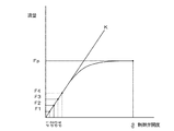
図2は制御弁2の入口4の圧力Pの下で制御弁2の開度dを変えて、得られた流量Fをグラフ化したものである。これにより、初期の立ち上がり部分から勾配Kと、制御弁2を全閉状態から最大開度dpまで開いた時の流量Fpが定義される。
FIG. 2 is a graph showing the flow rate F obtained by changing the opening degree d of the
図3は入口4の圧力をPa〜Pdまで変えた場合のグラフ図である。図3から、各圧力における勾配Ka、Kb、Kc、Kdと最大開度dpでの流量Fap、Fbp、Fcp、Fdpがそれぞれ求められる。
FIG. 3 is a graph when the pressure at the
図4は各開度における流量値を、それぞれの制御弁2の最大開度dpでの流量Fap、Fbp、Fcp、Fdpで除して正規化した流量をグラフ化したものである。図4に示すように正規化された流量は、制御弁2の入口4の圧力がPaからPdまで変化しても、制御弁2の開度に対してはほぼ一致して概略1本の曲線で表されるようになり、この曲線の立ち上がりの線形部分から、入口4の圧力には依存しない正規化された比例定数Kzが定義される。この正規化比例定数Kzは圧力に依存しないため、入口4の圧力が一定の状態で求めた開度と流量の直線部分の勾配を、最大開度dpでの流量Fpで除すことによって求めることができる。
FIG. 4 is a graph showing the flow rate values normalized by dividing the flow rate value at each opening by the flow rates Fap, Fbp, Fcp, and Fdp at the maximum opening dp of each
正規化比例定数Kzは図3に示す入口4の各圧力に応じた勾配(Ka〜Kd)と、それぞれの制御弁2の最大開度dpにおける流量(Fap〜Fdp)との比に相当し、次の(1)式で表すことができる。
Kz=Ka/Fap=Kb/Fbp=Kc/Fcp=Kd/Fdp・・(1)
The normalized proportionality constant Kz corresponds to the ratio between the gradient (Ka to Kd) corresponding to each pressure of the
Kz = Ka / Fap = Kb / Fbp = Kc / Fcp = Kd / Fdp (1)
図3から分かるように、いま流量制御時の環境条件が変化して、入口4の圧力が例えば図示しないPeになったとすると、そのときの勾配Ke及びその逆数である比例ゲイン(1/Ke)も変わるはずである。この際に、勾配Keは(1)式を変換した(2)式のように表すことができる。
Ke=Kz×Fep ・・・(2)
As can be seen from FIG. 3, if the environmental conditions at the time of flow rate control change and the pressure at the
Ke = Kz × Fep (2)
(2)式は求めるべき勾配Keが正規化比例定数Kzに最大開度dpの流量Fepを乗ずることにより得られることを示している。このとき、正規化比例定数Kzは前述の方法に従って、入口4の或る一定の圧力における勾配と最大開度dpでの流量から求め、予め演算制御装置7に記憶させておけばよいが、入口4の圧力が変化した場合の最大開度dpでの流量については、これを制御動作中に毎回計測することは事実上不可能に近い。
Equation (2) indicates that the gradient Ke to be obtained is obtained by multiplying the normalized proportionality constant Kz by the flow rate Fep of the maximum opening dp. At this time, the normalized proportional constant Kz may be obtained from the gradient at a certain pressure at the
この課題を解消するために、本実施例では制御弁2の前後の第1の圧力損失と流量計3で測定した流量とから、制御弁2の最大開度dpでの流量Fpを自動的に推定している。
In order to solve this problem, in the present embodiment, the flow rate Fp at the maximum opening dp of the
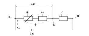
図5は上記システムをモデル化した等価回路であり、等価回路の各記号を次のように定義する。 FIG. 5 is an equivalent circuit that models the above system. Symbols of the equivalent circuit are defined as follows.
ΔP:制御弁2の入口4と出口5との間の差圧センサ6で実測される第1の圧力損失。
ΔE:制御弁2の入口4から流量計3を経て流量計出口8間に生ずる推定の第2の圧力損失。
F:流量計3で実測される流量。
r’:入口4と流量計出口8との間の制御弁2を除いた流量計3、配管1内の抵抗。
r:制御弁2を最大開度dpにしたときに制御弁2、配管1、流量計3に発生する推定の全抵抗(r=R0+r’)。
R0:最大開度dpにおいて制御弁2が有する固有抵抗。
R:制御弁2の開度に依存する制御弁2の抵抗であり、固有抵抗R0に上乗せされた制御弁2の抵抗であって、開度が大きくなると共に減少し、最大開度dpではR=0と見倣せる。
ΔP: a first pressure loss measured by the
ΔE: an estimated second pressure loss that occurs between the
F: Flow rate actually measured by the
r ′: resistance in the
r: Estimated total resistance (r = R0 + r ′) generated in the
R0: Specific resistance of the
R: resistance of the
図5に示した本システムの等価回路から、第1、第2の圧力損失ΔP、ΔEに関して、次の(3)、(4)式が誘導される。
ΔP=(R+R0)×F ・・・(3)
ΔP=ΔE−r’×F ・・・(4)
From the equivalent circuit of this system shown in FIG. 5, the following equations (3) and (4) are derived for the first and second pressure losses ΔP and ΔE.
ΔP = (R + R0) × F (3)
ΔP = ΔE−r ′ × F (4)
(3)、(4)式を展開すると、次式が得られる。
(R+R0)×F=ΔE−r’×F
(R+R0+r’)×F=ΔE
When the expressions (3) and (4) are expanded, the following expression is obtained.
(R + R0) × F = ΔE−r ′ × F
(R + R0 + r ′) × F = ΔE
この式から、F=ΔE/(R+R0+r’)の関係が求まる。ここで、最大開度dpのときはR=0になると見倣すことができ、また制御弁2の最大開度dpにおける全抵抗rは前述の通り、r=R0+r’になるため、最大開度dpでの流量Fpは、次の(5)式によって求まることになる。
Fp=ΔE/r ・・・(5)
From this equation, the relationship F = ΔE / (R + R0 + r ′) is obtained. Here, it can be assumed that when the maximum opening degree dp is R = 0, and the total resistance r at the maximum opening degree dp of the
Fp = ΔE / r (5)
このように、制御弁2の最大開度dpの時の流量Fpは、配管1内の第2の圧力損失ΔEと、制御弁2の最大開度dpにおける全抵抗rから演算により求まる。
Thus, the flow rate Fp at the maximum opening dp of the
以上の考え方に基づいて、(6)式に従って最大流量Fpを求め、(2)式に戻って得た比例勾配Keから比例ゲイン(1/Ke)を求めて自動的に更新する。そのために、予めオフラインにおいて制御プロセスの条件を求めておき、オンラインにおいてこれらの条件を使用して比例ゲインを更新すればよい。 Based on the above concept, the maximum flow rate Fp is obtained according to the equation (6), the proportional gain (1 / Ke) is obtained from the proportional gradient Ke obtained by returning to the equation (2), and is automatically updated. For this purpose, the control process conditions are obtained offline in advance, and the proportional gain is updated online using these conditions.
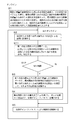
図6は実施例1の動作のフローチャート図を示す。演算制御装置7に内蔵したプログラムによりオフラインのステップS1においては、予備工程として、前述の方法で求めた制御弁2の開度と流量との対応関係から求めた勾配の逆数と、正規化比例定数Kzと、制御弁2の最大開度における固有抵抗R0をそれぞれ求めて、演算制御装置7にプロセスの定数として予め入力する。
FIG. 6 is a flowchart of the operation of the first embodiment. In step S1 which is offline by the program built in the arithmetic and
制御弁2の固有抵抗R0は、制御弁2の最大開度dpにおいて定義される固定抵抗である。また、制御弁2の入口4と出口5間に生ずる第1の圧力損失ΔPは制御弁2の最大開度dpでの流量Fpに比例するので、(6)式が成立する。
ΔP=R0×Fp ・・・・・・・・・(6)
The specific resistance R0 of the
ΔP = R0 × Fp (6)
固有抵抗R0を求めるには、制御弁2を最大開度dpまで開き、制御弁2の入口4の圧力を変えて、複数の第1の圧力損失ΔPと最大開度dpでの流量Fpの複数のデータを得て(6)式に代入し、連立方程式を解けばよい。
In order to obtain the specific resistance R0, the
第2の圧力損失ΔE、制御弁2の最大開度dpの全抵抗rについては、初期値として、例えば仮の値を演算制御装置7に記憶しておけばよい。
For the second pressure loss ΔE and the total resistance r of the maximum opening dp of the
オンラインにおいては、ステップS2で制御弁2の入口4と出口5との間に生ずる流体の第1の圧力損失ΔP、流量計3による流量とを逐時に求め、複数組のデータを取り込んで、演算制御装置7に記憶する。
On-line, the first pressure loss ΔP of the fluid generated between the
ここに第1の圧力損失ΔPは、制御弁2が最大開度dpのときの全抵抗r=R0+r’の関係を(4)式に代入した(7)式によって表される。
ΔP=ΔE−(r−R0)×F ・・・・・(7)
Here, the first pressure loss ΔP is expressed by equation (7) in which the relationship of total resistance r = R0 + r ′ when the
ΔP = ΔE− (r−R0) × F (7)
ステップS3において、流量計3で求めた流量Fと、第1の圧力損失ΔPの複数組のデータと、予め入力されている抵抗R0とを、(7)式にそれぞれ代入した複数の式による連立方程式を解くと、運転中の第2の圧力損失ΔE、制御弁2の最大開度dpの全抵抗rを求めることができる。得られた第2の圧力損失ΔE、制御弁2の最大開度dpの全抵抗rはそれまでの記憶値と置換され、演算制御装置7に記憶される。
In step S3, the flow rate F obtained by the
更にステップS4において、ステップS3で求めた第2の圧力損失ΔEと、全抵抗rを(5)式に代入すると、制御弁2の最大開度dpでの最大流量Fpが新たに算出される。比例ゲイン(1/Kf)は最大流量FpとオフラインのステップS1で初期設定しておいた正規化比例定数Kzから、次の(8)式に従って求められる。得られた比例ゲイン(1/Kf)は新たな最適値として更新される。
1/Kf=1/(Kz×Fp) ・・・(8)
Further, in step S4, when the second pressure loss ΔE obtained in step S3 and the total resistance r are substituted into the equation (5), the maximum flow rate Fp at the maximum opening dp of the
1 / Kf = 1 / (Kz × Fp) (8)
そしてステップS5において、この比例ゲイン(1/Kf)を用いて制御弁2を駆動する。
In step S5, the
このように、ステップS2〜S5の手順に従って、逐時に最適な比例ゲイン(1/Kf)を求めて、演算制御装置7で自動更新することを繰り返し、この比例ゲインによるフィードバックによる比例動作制御を行うことにより、継続して応答性の良い流量制御が可能になる。
In this way, according to the procedure of steps S2 to S5, the optimum proportional gain (1 / Kf) is obtained every time and is automatically updated by the arithmetic and
これまで、制御弁2の最大開度dpとそれに対応する流量を最大流量Fpと定義したが、最大開度dpとは必ずしも制御弁2を全開した状態での開度とする必要はなく、制御の際に制御弁2が通常に作動する開度範囲を規定し、その開度範囲内で最も開いた状態を最大開度dpとしてもよい。
Up to now, the maximum opening dp of the
図7は実施例2の動作フローチャート図である。実施例1の図6のステップS2とS3の間に、ステップS11、S12が加えられている。 FIG. 7 is an operation flowchart of the second embodiment. Steps S11 and S12 are added between steps S2 and S3 in FIG. 6 of the first embodiment.
実際に、オンラインで流体の流量を制御する場合に、制御弁2の入口4の圧力の僅かな変化に敏感に対応して比例ゲインを頻繁に変更するよりは、第1の圧力損失ΔPの変化量に所定の閾値を設けて、一定以上の変化幅が得られた場合にのみ、比例ゲインを更新した方が制御が円滑になる場合がある。
In fact, when the fluid flow rate is controlled on-line, the change in the first pressure loss ΔP is more frequent than the proportional gain is frequently changed in response to a slight change in the pressure at the
そのため、実施例2のステッ プS11では、実施した制御弁2による第1の圧力損失ΔPと流量Fとから、記憶されている第2の圧力損失ΔEから制御弁2の抵抗r’(r’=r−R0)による圧力損失を差し引いた値との差を求め、それをパラメータMと定義する。このパラメータMは(9)式のように表される。
M=|ΔE−(r−R0)×F−ΔP| ・・・(9)
Therefore, in step S11 of the second embodiment, the resistance r ′ (r ′) of the
M = | ΔE− (r−R0) × F−ΔP | (9)
運転中はパラメータMの変化から現在設定されている比例ゲインが最適かどうかを常に監視し、ステップS12でパラメータMが閾値を超えて、比例ゲインの最適状態からのずれを確認すると、それを更新する作業を次のステップS3において行う。つまり、パラメータMが閾値を超えた場合には、ステップS3で第2の圧力損失△E、全抵抗rを求め、ステップS4で新たな比例ゲイン(1/Kf)を求め、ステップS5に進む。 During operation, it is always monitored whether the currently set proportional gain is optimal based on the change in parameter M. If parameter M exceeds the threshold in step S12 and the deviation from the optimal state of proportional gain is confirmed, it is updated. The operation to be performed is performed in the next step S3. That is, when the parameter M exceeds the threshold value, the second pressure loss ΔE and the total resistance r are obtained in step S3, a new proportional gain (1 / Kf) is obtained in step S4, and the process proceeds to step S5.
一方、パラメータMが閾値よりも小さければ、現在設定されている比例ゲインでよいと判断し、ステップS3、S4を省略し、ステップS5に進む。 On the other hand, if the parameter M is smaller than the threshold value, it is determined that the currently set proportional gain is sufficient, and steps S3 and S4 are omitted, and the process proceeds to step S5.
ステップS5においては、得られている比例ゲイン(1/Kf)により実施例1と同様な制御を行う。 In step S5, control similar to that in the first embodiment is performed using the obtained proportional gain (1 / Kf).
1 配管
2 制御弁
3 流量計
4 制御弁入口
5 制御弁出口
6 差圧センサ
7 演算制御装置
8 流量計出口
1 Piping 2
Claims (4)
前記オフラインにおいては、前記制御弁の入口側の圧力を一定にして、前記制御弁を全閉状態と最大開度の間で駆動して、前記制御弁の開度と前記流量計から得た流量との対応関係から求めた勾配の逆数と、前記制御弁の最大開度における流量により前記勾配を除して得られる正規化比例定数と、前記制御弁の最大開度における制御弁の固有抵抗とを予め求めて演算制御装置に設定すると共に、前記制御弁の入口から前記流量計を経て前記流量計出口間に生ずる第2の圧力損失と、前記制御弁を最大開度にしたときに制御弁、配管、流量計に発生する全抵抗との初期値を前記演算制御装置に予め入力する予備工程を有し、
前記オンラインにおいては、作動中の前記制御弁により生ずる前記制御弁の前後の差圧である第1の圧力損失と、前記流量計によりそのときの流量とを逐時に求める第1の工程と、
該第1の工程で得られた前記第1の圧力損失と前記流量とから成る複数のデータを基に、前記制御弁と前記流量計を含む配管により生ずる第2の圧力損失と、前記制御弁の最大開度における前記制御弁と前記流量計とを含む配管による全抵抗とを演算で求める第2の工程と、
該第2の工程で求めた前記第2の圧力損失と前記全抵抗とに基づいて、前記制御弁の最大開度での流量を演算によって求める第3の工程と、
該第3の工程で求めた前記制御弁の前記最大開度での流量と前記オフラインで設定した前記正規化比例定数とを基に前記勾配を算出し、その逆数から新たな前記比例ゲインを求めて前記演算制御装置に設定する第4の工程と、
前記流量計により流量を測定しながら前記比例ゲインを用いた比例制御動作により前記制御弁を駆動して前記流量をフィードバック制御する第5の工程とから成り、
前記第1〜第5の工程を繰り返すことを特徴とする流量制御方法。 When the flow rate of fluid is measured by a flow meter and the control valve is driven by proportional control operation using proportional gain to perform flow control, the control process conditions are obtained offline in advance, and these conditions are set online. In the flow rate control method in which the proportional gain is updated using and the flow rate control is performed using the updated proportional gain,
In the offline mode, the pressure on the inlet side of the control valve is made constant, the control valve is driven between the fully closed state and the maximum opening, and the opening of the control valve and the flow rate obtained from the flow meter Reciprocal of the gradient obtained from the corresponding relationship, normalized proportionality constant obtained by dividing the gradient by the flow rate at the maximum opening of the control valve, and the specific resistance of the control valve at the maximum opening of the control valve, Is obtained in advance and set in the arithmetic and control unit, and the second pressure loss that occurs between the inlet of the control valve, the flow meter and the outlet of the flow meter, and the control valve when the control valve is at the maximum opening degree. , Having a preliminary step of inputting the initial value of the total resistance generated in the pipe and the flow meter to the arithmetic control device in advance,
In the online, a first step of obtaining a first pressure loss that is a differential pressure before and after the control valve generated by the operating control valve and a flow rate at that time by the flow meter,
A second pressure loss caused by a pipe including the control valve and the flow meter based on a plurality of data including the first pressure loss and the flow rate obtained in the first step; A second step of calculating the total resistance by piping including the control valve and the flow meter at the maximum opening of
A third step of calculating the flow rate at the maximum opening of the control valve based on the second pressure loss and the total resistance determined in the second step;
The gradient is calculated based on the flow rate at the maximum opening of the control valve obtained in the third step and the normalized proportionality constant set off-line, and a new proportional gain is obtained from the reciprocal thereof. A fourth step of setting in the arithmetic and control unit;
A fifth step of feedback controlling the flow rate by driving the control valve by a proportional control operation using the proportional gain while measuring the flow rate by the flow meter,
A flow rate control method characterized by repeating the first to fifth steps.
Priority Applications (1)
| Application Number | Priority Date | Filing Date | Title |
|---|---|---|---|
| JP2008135106A JP2009282819A (en) | 2008-05-23 | 2008-05-23 | Flow control method |
Applications Claiming Priority (1)
| Application Number | Priority Date | Filing Date | Title |
|---|---|---|---|
| JP2008135106A JP2009282819A (en) | 2008-05-23 | 2008-05-23 | Flow control method |
Publications (2)
| Publication Number | Publication Date |
|---|---|
| JP2009282819A true JP2009282819A (en) | 2009-12-03 |
| JP2009282819A5 JP2009282819A5 (en) | 2011-04-07 |
Family
ID=41453201
Family Applications (1)
| Application Number | Title | Priority Date | Filing Date |
|---|---|---|---|
| JP2008135106A Pending JP2009282819A (en) | 2008-05-23 | 2008-05-23 | Flow control method |
Country Status (1)
| Country | Link |
|---|---|
| JP (1) | JP2009282819A (en) |
Cited By (4)
| Publication number | Priority date | Publication date | Assignee | Title |
|---|---|---|---|---|
| KR20140004583A (en) * | 2012-07-03 | 2014-01-13 | 가부시키가이샤 호리바 에스텍 | Pressure control device, flow rate control device and recording medium having programs used for pressure control device, recording medium having programs used for flow rate control device |
| KR20180097456A (en) * | 2017-02-23 | 2018-08-31 | 아즈빌주식회사 | Apparatus for estimating maintenance decision indicator, flow rate controlling apparatus, and method for estimating maintenance decision indicator |
| WO2019049211A1 (en) * | 2017-09-05 | 2019-03-14 | 富士通株式会社 | Estimation method, estimation device, and estimation system |
| JPWO2019077668A1 (en) * | 2017-10-17 | 2020-01-16 | 株式会社Fuji | Machine tool equipment |
-
2008
- 2008-05-23 JP JP2008135106A patent/JP2009282819A/en active Pending
Cited By (7)
| Publication number | Priority date | Publication date | Assignee | Title |
|---|---|---|---|---|
| KR20140004583A (en) * | 2012-07-03 | 2014-01-13 | 가부시키가이샤 호리바 에스텍 | Pressure control device, flow rate control device and recording medium having programs used for pressure control device, recording medium having programs used for flow rate control device |
| KR101990155B1 (en) | 2012-07-03 | 2019-06-17 | 가부시키가이샤 호리바 에스텍 | Pressure control device, flow rate control device and recording medium having programs used for pressure control device, recording medium having programs used for flow rate control device |
| KR20180097456A (en) * | 2017-02-23 | 2018-08-31 | 아즈빌주식회사 | Apparatus for estimating maintenance decision indicator, flow rate controlling apparatus, and method for estimating maintenance decision indicator |
| KR101951592B1 (en) | 2017-02-23 | 2019-02-22 | 아즈빌주식회사 | Apparatus for estimating maintenance decision indicator, flow rate controlling apparatus, and method for estimating maintenance decision indicator |
| WO2019049211A1 (en) * | 2017-09-05 | 2019-03-14 | 富士通株式会社 | Estimation method, estimation device, and estimation system |
| JPWO2019049211A1 (en) * | 2017-09-05 | 2020-03-26 | 富士通株式会社 | Estimation method, estimation device and estimation system |
| JPWO2019077668A1 (en) * | 2017-10-17 | 2020-01-16 | 株式会社Fuji | Machine tool equipment |
Similar Documents
| Publication | Publication Date | Title |
|---|---|---|
| TWI406119B (en) | A system for remotely controlling pressure within a zone and a chemical mechanical polishing machine system | |
| KR101616582B1 (en) | Flow controller | |
| JP5613748B2 (en) | System and method for flow monitoring and control | |
| KR101516924B1 (en) | Adaptive control device and adaptive control method, as well as control device and control method for injection molding machine | |
| US8146481B2 (en) | Actuator, actuator control method, and actuator control program | |
| KR20150060788A (en) | Method and apparatus for self verification of pressure based mass flow controllers | |
| KR20140004583A (en) | Pressure control device, flow rate control device and recording medium having programs used for pressure control device, recording medium having programs used for flow rate control device | |
| WO2017008548A1 (en) | Flow control method for proportional valve of breathing machine | |
| JP2009282819A (en) | Flow control method | |
| CN108138761B (en) | Pneumatic system operation control device and control method | |
| JP5037443B2 (en) | Flow control method | |
| US20180120864A1 (en) | Nonlinear control of mass flow controller devices using sliding mode | |
| US9523365B2 (en) | Decoupling of controlled variables in a fluid conveying system with dead time | |
| JP2009282819A5 (en) | ||
| CN211015169U (en) | Control system for temperature of pipeline confluence liquid | |
| JP2010026576A5 (en) | ||
| JP2005004742A (en) | Device and method for batch property estimation | |
| CN110908414A (en) | System and method for controlling temperature of pipeline confluence liquid | |
| JP6773530B2 (en) | End pressure control device and end pressure control method | |
| JP7473397B2 (en) | Mass flow controller and hunting suppression method | |
| KR20170137640A (en) | A closed-loop control device for controlling at least one control value of at least one tempering circle | |
| KR101842160B1 (en) | Flow rate control apparatus and method | |
| CN111971636A (en) | Flow rate control device, diagnostic method, and program for flow rate control device | |
| JP2020009111A (en) | Estimation device and pressure control valve | |
| Al Amin et al. | Nonlinear model predictive control of a Hammerstein Weiner model based experimental managed pressure drilling setup [J] |
Legal Events
| Date | Code | Title | Description |
|---|---|---|---|
| A521 | Written amendment |
Effective date: 20110217 Free format text: JAPANESE INTERMEDIATE CODE: A523 |
|
| A621 | Written request for application examination |
Effective date: 20110217 Free format text: JAPANESE INTERMEDIATE CODE: A621 |
|
| A977 | Report on retrieval |
Free format text: JAPANESE INTERMEDIATE CODE: A971007 Effective date: 20120725 |
|
| A131 | Notification of reasons for refusal |
Free format text: JAPANESE INTERMEDIATE CODE: A131 Effective date: 20120731 |
|
| A601 | Written request for extension of time |
Free format text: JAPANESE INTERMEDIATE CODE: A601 Effective date: 20121029 |
|
| A602 | Written permission of extension of time |
Free format text: JAPANESE INTERMEDIATE CODE: A602 Effective date: 20121101 |
|
| A601 | Written request for extension of time |
Free format text: JAPANESE INTERMEDIATE CODE: A601 Effective date: 20121129 |
|
| A602 | Written permission of extension of time |
Free format text: JAPANESE INTERMEDIATE CODE: A602 Effective date: 20121204 |
|
| A601 | Written request for extension of time |
Free format text: JAPANESE INTERMEDIATE CODE: A601 Effective date: 20121228 |
|
| A602 | Written permission of extension of time |
Effective date: 20130108 Free format text: JAPANESE INTERMEDIATE CODE: A602 |
|
| A521 | Written amendment |
Free format text: JAPANESE INTERMEDIATE CODE: A523 Effective date: 20130130 |
|
| A02 | Decision of refusal |
Effective date: 20130604 Free format text: JAPANESE INTERMEDIATE CODE: A02 |