JP2009282502A - Apparatus, methods and systems for providing lighting and communication - Google Patents
Apparatus, methods and systems for providing lighting and communication Download PDFInfo
- Publication number
- JP2009282502A JP2009282502A JP2009074726A JP2009074726A JP2009282502A JP 2009282502 A JP2009282502 A JP 2009282502A JP 2009074726 A JP2009074726 A JP 2009074726A JP 2009074726 A JP2009074726 A JP 2009074726A JP 2009282502 A JP2009282502 A JP 2009282502A
- Authority
- JP
- Japan
- Prior art keywords
- solid state
- state light
- mode
- light emitting
- panels
- Prior art date
- Legal status (The legal status is an assumption and is not a legal conclusion. Google has not performed a legal analysis and makes no representation as to the accuracy of the status listed.)
- Pending
Links
Images


Classifications
-
- H—ELECTRICITY
- H05—ELECTRIC TECHNIQUES NOT OTHERWISE PROVIDED FOR
- H05B—ELECTRIC HEATING; ELECTRIC LIGHT SOURCES NOT OTHERWISE PROVIDED FOR; CIRCUIT ARRANGEMENTS FOR ELECTRIC LIGHT SOURCES, IN GENERAL
- H05B33/00—Electroluminescent light sources
- H05B33/02—Details
-
- H—ELECTRICITY
- H05—ELECTRIC TECHNIQUES NOT OTHERWISE PROVIDED FOR
- H05B—ELECTRIC HEATING; ELECTRIC LIGHT SOURCES NOT OTHERWISE PROVIDED FOR; CIRCUIT ARRANGEMENTS FOR ELECTRIC LIGHT SOURCES, IN GENERAL
- H05B47/00—Circuit arrangements for operating light sources in general, i.e. where the type of light source is not relevant
- H05B47/10—Controlling the light source
- H05B47/175—Controlling the light source by remote control
- H05B47/18—Controlling the light source by remote control via data-bus transmission
-
- G—PHYSICS
- G09—EDUCATION; CRYPTOGRAPHY; DISPLAY; ADVERTISING; SEALS
- G09F—DISPLAYING; ADVERTISING; SIGNS; LABELS OR NAME-PLATES; SEALS
- G09F13/00—Illuminated signs; Luminous advertising
- G09F13/20—Illuminated signs; Luminous advertising with luminescent surfaces or parts
- G09F13/22—Illuminated signs; Luminous advertising with luminescent surfaces or parts electroluminescent
-
- G—PHYSICS
- G09—EDUCATION; CRYPTOGRAPHY; DISPLAY; ADVERTISING; SEALS
- G09F—DISPLAYING; ADVERTISING; SIGNS; LABELS OR NAME-PLATES; SEALS
- G09F13/00—Illuminated signs; Luminous advertising
- G09F13/04—Signs, boards or panels, illuminated from behind the insignia
- G09F13/0418—Constructional details
- G09F2013/05—Constructional details indicating exit way or orientation
-
- G—PHYSICS
- G09—EDUCATION; CRYPTOGRAPHY; DISPLAY; ADVERTISING; SEALS
- G09F—DISPLAYING; ADVERTISING; SIGNS; LABELS OR NAME-PLATES; SEALS
- G09F13/00—Illuminated signs; Luminous advertising
- G09F13/20—Illuminated signs; Luminous advertising with luminescent surfaces or parts
- G09F13/22—Illuminated signs; Luminous advertising with luminescent surfaces or parts electroluminescent
- G09F2013/222—Illuminated signs; Luminous advertising with luminescent surfaces or parts electroluminescent with LEDs
Abstract
Description
本発明は発光に関し、より詳細には、固体発光パネルに関する。 The present invention relates to light emission, and more particularly to a solid state light emission panel.
固体発光パネルは、ディスプレイ用の固体バックライトユニット、全体照明用の発光パネル、標識用のバックライトとして、かつ/または他の目的に使用されることがある。例えば、固体バックライトユニットは、複数の離散光源からなる2次元アレイの前に置かれたLCDスクリーンなどによって生成されたグラフィックスを介して情報を伝達し得るディスプレイに使用されることがある。 The solid state light emitting panel may be used as a solid state backlight unit for displays, a light emitting panel for general illumination, a backlight for signs, and / or for other purposes. For example, solid state backlight units may be used in displays that can communicate information via graphics generated by LCD screens or the like placed in front of a two-dimensional array of discrete light sources.
全体照明用の発光パネルは、照明を提供するのに使用し得るが、LCDスクリーンその他の静的なテンプレートおよび/またはフィルタなどの情報コンテンツコンポーネントがないと、普通は、照明以外の追加機能は提供されない。 Luminous panels for overall lighting can be used to provide lighting, but usually without additional information content components such as LCD screens or other static templates and / or filters, provide additional functions other than lighting Not.
発光および伝達用の機器、方法、およびシステムが提供される。いくつかの実施形態では、機器は、複数の固体発光体を含む固体発光パネルと、これらの固体発光体を、ある区域を照明する第1のモードおよびこの区域内でメッセージを伝達する第2のモードで制御するように構成されたマルチモード発光パネルコントローラとを含み得る。 Devices, methods, and systems for light emission and transmission are provided. In some embodiments, an apparatus includes a solid state light emitting panel that includes a plurality of solid state light emitters, a first mode that illuminates the area with the solid state light emitter, and a second mode that transmits a message within the area. And a multi-mode light emitting panel controller configured to control in mode.
いくつかの実施形態では、このマルチモードコントローラは、入力信号を受け取るように構成された入力モジュールを含み、入力信号に応答して第1のモードおよび/または第2のモードを選択する。いくつかの実施形態では、固体発光体は、第1のモードに対応する複数の第1の色の発光器と、第2のモードに対応する複数の第2の色の発光器とを含む。 In some embodiments, the multi-mode controller includes an input module configured to receive an input signal and selects a first mode and / or a second mode in response to the input signal. In some embodiments, the solid state light emitter includes a plurality of first color light emitters corresponding to the first mode and a plurality of second color light emitters corresponding to the second mode.
いくつかの実施形態では、固体発光体の少なくとも一部は、第1のモードでは白色光を出射し、第2のモードでは非白色光を出射するように構成された個々にアドレス指定可能なマルチカラー固体発光体を含み、固体発光体は、情報を伝える画像を表示するように選択的に動作する。 In some embodiments, at least some of the solid state light emitters are individually addressable multi-channels configured to emit white light in the first mode and non-white light in the second mode. Including a color solid state light emitter, the solid state light emitter is selectively operated to display an image carrying information.
いくつかの実施形態では、メッセージは、アレイ選択により形成される記号を介してメッセージを共同して伝達する固体発光体の一部を介して伝達される。いくつかの実施形態では、マルチモードコントローラは、文字メッセージが表示されるように固体発光体を選択的に制御するように構成される。いくつかの実施形態は、入力信号に対応するシーケンスに従い動的な構成で光を出射する手段を備える。 In some embodiments, the message is communicated via a portion of a solid state light emitter that jointly conveys the message via symbols formed by array selection. In some embodiments, the multi-mode controller is configured to selectively control the solid state light emitter such that a text message is displayed. Some embodiments comprise means for emitting light in a dynamic configuration according to a sequence corresponding to the input signal.
本発明のいくつかの実施形態による方法は、固体発光パネル内の複数の第1の色の固体発光体および複数の第2の色の固体発光体を動作させることによってある区域を照明することを含み得る。これらの方法はさらに、複数の第2の色の固体発光体を選択的に動作させることによって固体発光パネルを介してメッセージを伝達することを含み得る。 A method according to some embodiments of the present invention comprises illuminating an area by operating a plurality of first color solid state light emitters and a plurality of second color solid state light emitters in a solid state light emitting panel. May be included. These methods may further include communicating a message through the solid state lighting panel by selectively operating a plurality of second color solid state light emitters.
いくつかの実施形態では、メッセージの伝達は、複数の第2の色の固体発光体を選択的に動作させて、情報を伝えるように構成された画像を形成することを含む。 In some embodiments, communicating the message includes selectively operating a plurality of second color solid state light emitters to form an image configured to convey the information.
いくつかの実施形態では、複数の第1の色の固体発光体は、波長変換蛍光体を被覆した青色発光LEDを含む。いくつかの実施形態では、複数の第2の色の固体発光体は、赤色発光LEDを含む。いくつかの実施形態は、複数の第2の色の固体発光体を選択的に動作させることを含み、これら複数の第2の色の固体発光体は個々にアドレス指定可能である。 In some embodiments, the plurality of first color solid state light emitters comprises a blue light emitting LED coated with a wavelength converting phosphor. In some embodiments, the plurality of second color solid state light emitters includes a red light emitting LED. Some embodiments include selectively operating a plurality of second color solid state light emitters, wherein the plurality of second color solid state light emitters are individually addressable.
いくつかの実施形態は、伝達モード信号を受け取ることを含み、メッセージはこの伝達モード信号に応答するものである。いくつかの実施形態では、伝達モード信号は、中央システムコントローラから得られ、離れたところにある環境状態センサから受け取るデータに応答して選択的に更新される。 Some embodiments include receiving a transmission mode signal and the message is responsive to the transmission mode signal. In some embodiments, the transmission mode signal is obtained from the central system controller and selectively updated in response to data received from remote environmental condition sensors.
本発明のいくつかの実施形態は、照明および伝達用のシステムを含む。このようなシステムの実施形態は、制御信号に応答して、第1のモードでは照明を提供し、第2のモードでは情報を伝達するように構成されたマルチモード固体発光パネルと、少なくとも1つのマルチモード固体発光パネルに制御信号を送出するように構成された中央コントローラとを含み得る。 Some embodiments of the present invention include a system for illumination and transmission. An embodiment of such a system is responsive to a control signal to provide illumination in a first mode and communicate information in a second mode, and at least one And a central controller configured to send control signals to the multi-mode solid state lighting panel.
いくつかの実施形態は、中央コントローラおよび/またはマルチモード固体発光パネルに環境情報信号を提供するように構成された環境状態センサを備える。いくつかの実施形態では、中央コントローラはさらに、環境情報信号の受信に応答して、少なくとも1つのマルチモード固体発光パネルに更新された制御信号を送出するように構成される。いくつかの実施形態では、この少なくとも1つのマルチモード固体発光パネルはさらに、この更新された制御信号に応答して、更新された情報を伝達するように構成される。 Some embodiments comprise an environmental condition sensor configured to provide environmental information signals to the central controller and / or the multi-mode solid state lighting panel. In some embodiments, the central controller is further configured to send an updated control signal to the at least one multimode solid state lighting panel in response to receiving the environmental information signal. In some embodiments, the at least one multimode solid state lighting panel is further configured to communicate updated information in response to the updated control signal.
いくつかの実施形態では、この少なくとも1つのマルチモード固体発光パネルはさらに、環境情報信号に応答して、更新された情報を伝達するように構成される。いくつかの実施形態では、マルチモード固体発光パネルは複数の固体発光体を含み、これらの固体発光体の第1の部分は第1のモードで動作し、これらの固体発光体の第2の部分は第2のモードで動作する。 In some embodiments, the at least one multi-mode solid state lighting panel is further configured to communicate updated information in response to an environmental information signal. In some embodiments, the multi-mode solid state lighting panel includes a plurality of solid state light emitters, a first portion of these solid state light emitters operating in a first mode, and a second portion of these solid state light emitters. Operates in the second mode.
いくつかの実施形態では、マルチモード固体発光パネルは、個々にアドレス指定可能な複数のマルチカラー固体発光体を含み、これら個々にアドレス指定可能なマルチカラー固体発光体は、制御信号に応答して選択的に動作する。いくつかの実施形態では、マルチモード固体発光パネルはさらに、複数の固体発光体の選択的動作によって形成され動的に提示される複数の画像を介して第2のモードで情報を伝達するように構成される。 In some embodiments, the multi-mode solid state lighting panel includes a plurality of individually addressable multi-color solid state light emitters that are responsive to the control signal. Operates selectively. In some embodiments, the multi-mode solid state lighting panel is further configured to communicate information in the second mode via a plurality of images that are formed and dynamically presented by selective operation of the plurality of solid state light emitters. Composed.
本発明のいくつかの実施形態は、固体発光パネルを含む機器を備える。この固体発光パネルは、複数の固体発光体と、発光パネル群コントローラから入力信号を受け取るように構成された入力モジュールとを含み得る。この発光パネル群コントローラは、人のスペース(personnel space)の上にそれぞれ離して配置され、それによって人のスペースのかなりの部分にわたって照明を分散させる複数の固体発光パネルを協調して制御するように構成し得る。 Some embodiments of the invention comprise an apparatus that includes a solid state lighting panel. The solid state light emitting panel may include a plurality of solid state light emitters and an input module configured to receive an input signal from the light emitting panel group controller. The light-emitting panel group controller is arranged so as to be coordinated to control a plurality of solid-state light-emitting panels that are spaced apart from each other on the person space, thereby distributing the illumination over a substantial portion of the person's space. Can be configured.
いくつかの実施形態では、発光パネル群コントローラは、ある区域を照明する第1のモードおよび情報を伝達する第2のモードで固体発光パネルを協調して制御するように構成し得る。いくつかの実施形態では、複数の固体発光パネルの少なくとも1つにおける固体発光体は、第1のモードに対応する複数の第1の色の発光器および第2のモードに対応する第2の色の発光器を含み得る。いくつかの実施形態では、固体発光パネルの第1の部分は、第1のモードおよび第2のモードに対応して点灯し、固体発光パネルの第2の部分は、第1のモードに対応して点灯するが、第2のモードに対応しては点灯しない。 In some embodiments, the lighting panel group controller may be configured to coordinately control the solid state lighting panels in a first mode that illuminates an area and a second mode that conveys information. In some embodiments, the solid state light emitter in at least one of the plurality of solid state light emitting panels includes a plurality of first color light emitters corresponding to the first mode and a second color corresponding to the second mode. Of light emitters. In some embodiments, the first part of the solid state light emitting panel is lit corresponding to the first mode and the second mode, and the second part of the solid state light emitting panel corresponds to the first mode. However, it does not light in correspondence with the second mode.
いくつかの実施形態では、固体発光パネル内の固体発光体は、複数の第1の色の発光器および第2の色の発光器を含む。第1の色の発光器は、第1のモードおよび第2のモードで固体発光パネルの第1の部分において点灯し、第2の色の発光器は、第2のモードに対応して固体発光パネルの第2の部分において点灯し得る。いくつかの実施形態は、入力信号に対応するシーケンスに従って動的な構成で固体発光パネルを選択的に動作させる手段を備える。 In some embodiments, the solid state light emitter in the solid state light emitting panel includes a plurality of first color light emitters and a second color light emitter. The first color light emitter is lit in the first part of the solid state light emission panel in the first mode and the second mode, and the second color light emitter is solid state light emission corresponding to the second mode. It can be lit in the second part of the panel. Some embodiments comprise means for selectively operating the solid state lighting panel in a dynamic configuration according to a sequence corresponding to the input signal.
本発明のいくつかの実施形態は、人のスペースにそれぞれ離して配置された複数の固体発光パネルを、発光パネル群コントローラから受け取る入力信号に応答して第1のモードで動作させることによってある区域を照明することを含み得る方法を含む。このような方法は、入力信号に応答して固体発光パネルの第1の部分を選択的に動作させることによって固体発光パネルを介して情報を伝達することを含み得る。 Some embodiments of the present invention provide an area by operating a plurality of solid state light emitting panels, each spaced apart in a human space, in a first mode in response to an input signal received from a light emitting panel group controller. Including a method that may include illuminating. Such a method may include communicating information through the solid state lighting panel by selectively operating a first portion of the solid state lighting panel in response to an input signal.
いくつかの実施形態では、固体発光パネルを介して情報を伝達することは、固体発光パネルの第2の部分を、入力信号に応答して第2のモードで選択的に動作させることを含む。いくつかの実施形態では、固体発光パネルの第2の部分のいくつかは、第1のモードではほぼ白色光を出射し、第2のモードではほぼ非白色光を出射するように構成されたマルチカラー固体発光体を含む。 In some embodiments, communicating information through the solid state lighting panel includes selectively operating a second portion of the solid state lighting panel in a second mode in response to an input signal. In some embodiments, some of the second portions of the solid state lighting panel are configured to emit substantially white light in the first mode and substantially non-white light in the second mode. Includes color solid state light emitters.
いくつかの実施形態では、発光パネル群コントローラは、ビルディングブロック制御システムを含み、いくつかの実施形態では、発光パネル群コントローラは、ビルディングブロック制御システム信号に応答して入力信号を生成する。いくつかの実施形態は、少なくとも1つの環境センサから受け取ったデータに応答して入力信号を生成することを含む。 In some embodiments, the lighting panel group controller includes a building block control system, and in some embodiments, the lighting panel group controller generates an input signal in response to the building block control system signal. Some embodiments include generating an input signal in response to data received from at least one environmental sensor.
本発明のいくつかの実施形態は、照明および伝達用のシステムを備える。このようなシステムのいくつかの実施形態は、人のスペースにそれぞれ離して配置された複数の固体発光パネルを含み、これら複数の固体発光パネルはそれぞれ、複数の固体発光体を含み、この固体発光パネルで受け取る入力信号に応答して第1のモードで照明を提供し、第2のモードで情報を伝達するように構成され得る。いくつかの実施形態は、固体発光パネルの少なくとも1つに入力信号を送出するように構成された発光パネル群コントローラを含み得る。 Some embodiments of the invention comprise a system for illumination and transmission. Some embodiments of such a system include a plurality of solid state light emission panels each spaced apart in a human space, each of the plurality of solid state light emission panels including a plurality of solid state light emitters, the solid state light emission It may be configured to provide illumination in a first mode and communicate information in a second mode in response to an input signal received at the panel. Some embodiments may include a lighting panel group controller configured to send an input signal to at least one of the solid state lighting panels.
いくつかの実施形態は、発光パネル群コントローラに環境情報信号を提供するように構成された環境状態センサを備える。いくつかの実施形態では、固体発光パネルは、第1のモードおよび第2のモードで照明を提供するように構成された第1の部分の固体発光パネルと、第1のモードでは照明を提供するが、第2のモードでは照明を提供しないように構成された第2の部分の固体発光パネルとを含み、第2のモードでの第1の部分と第2の部分の協調動作により情報が伝達される。 Some embodiments comprise an environmental condition sensor configured to provide an environmental information signal to the lighting panel group controller. In some embodiments, the solid state lighting panel provides a first portion of the solid state lighting panel configured to provide illumination in the first mode and the second mode, and illumination in the first mode. Includes a second part of the solid state light emitting panel configured not to provide illumination in the second mode, and information is transmitted by cooperative operation of the first part and the second part in the second mode. Is done.
いくつかの実施形態では、この情報は、脱出経路および/または緊急状態に関する指示を含む。いくつかの実施形態では、固体発光パネルの少なくとも1つは、ほぼ白色光を出射するように構成された第1の部分の固体発光体と、ほぼ非白色光を出射するように構成された第2の部分の固体発光体とを含む。第1の部分の固体発光体は、第1のモードに応答して光を出射するように構成し、第2の部分の固体発光体は、第2のモードの間中、光を出射するように構成し得る。 In some embodiments, this information includes instructions regarding escape routes and / or emergency conditions. In some embodiments, at least one of the solid state light emitting panels includes a first portion of a solid state light emitter configured to emit substantially white light and a first portion configured to emit substantially non-white light. 2 parts of solid state light emitter. The first portion of the solid state light emitter is configured to emit light in response to the first mode, and the second portion of the solid state light emitter is configured to emit light during the second mode. Can be configured.
いくつかの実施形態では、発光パネル群コントローラはさらに、環境状態センサによって生成される環境情報信号に応答して入力信号を生成するように構成される。いくつかの実施形態では、発光パネル群コントローラは、ビルディングブロック制御システムを含む。いくつかの実施形態では、発光パネル群コントローラはさらに、固体発光パネルに一連の入力信号を送出することによって第2のモードで情報を動的に伝達するように構成される。 In some embodiments, the lighting panel group controller is further configured to generate an input signal in response to an environmental information signal generated by the environmental condition sensor. In some embodiments, the lighting panel group controller includes a building block control system. In some embodiments, the lighting panel group controller is further configured to dynamically communicate information in the second mode by sending a series of input signals to the solid state lighting panel.
添付の図面は、本発明のさらなる理解が得られるように含められるものであり、本出願に組み込まれ、かつ、その一部をなすものである。添付の図面は、本発明のある種の1つ(または複数)の実施形態を示す。 The accompanying drawings are included to provide a further understanding of the invention, and are incorporated in and constitute a part of this application. The accompanying drawings illustrate one or more embodiments of the present invention.
本発明の実施形態を示す添付の図面を参照して、以下に本発明の実施形態をより詳細に説明する。ただし、本発明は、多くの異なる形態で実施することができ、本明細書に記載の実施形態に限定されると解釈すべきではない。そうではなく、これらの実施形態は、本開示が完全なものとなり、当業者に本発明の範囲が隅々まで伝えられるように提供されるものである。図面を通じて、同様の番号は同様の要素を指す。 Embodiments of the present invention will be described in more detail below with reference to the accompanying drawings showing embodiments of the present invention. However, the present invention may be implemented in many different forms and should not be construed as limited to the embodiments set forth herein. Rather, these embodiments are provided so that this disclosure will be thorough and complete, and will fully convey the scope of the invention to those skilled in the art. Like numbers refer to like elements throughout the drawings.
本明細書では第1、第2などという用語が様々な要素を説明するために用いられることがあるが、これらの要素はこれらの用語によって制限されるべきでないことを理解されたい。これらの用語は、ある要素を別の要素と区別するためにのみ用いられる。例えば、本発明の範囲を逸脱することなく、第1の要素を第2の要素と呼ぶことができ、同様に、第2の要素を第1の要素と呼ぶことができる。本明細書では、「および/または」という用語は、列挙された関連項目のうちの1つまたは複数の項目のありとあらゆる組合せを含む。 Although the terms first, second, etc. may be used herein to describe various elements, it should be understood that these elements should not be limited by these terms. These terms are only used to distinguish one element from another. For example, a first element can be referred to as a second element, and, similarly, a second element can be referred to as a first element, without departing from the scope of the present invention. As used herein, the term “and / or” includes any and all combinations of one or more of the associated listed items.
層、領域、または基板などの要素が別の要素の「上に」ある、または別の要素の「上まで」延びると書かれていれば、その要素は、直接別の要素の上にあるか、直接別の要素の上まで延びることもあり、また、介在する要素が存在することもあることを理解されたい。それに対して、ある要素が別の要素の「上に直接」ある、または別の要素の「上まで直接」延びると書かれていれば、介在する要素は存在しない。また、ある要素が別の要素に「接続」または「結合」されると書かれていれば、その要素は、別の要素に直接接続または結合されることもあり、または、介在する要素が存在することもあることも理解されたい。それに対して、ある要素が別の要素に「直接接続」または「直接結合」されると書かれていれば、介在する要素は存在しない。 If an element such as a layer, region, or substrate is written “on” or extending “above” another element, is that element directly on top of another element? It should be understood that it may extend directly over another element and that there may be intervening elements. In contrast, if an element is written “directly above” another element or extends “directly above” another element, there are no intervening elements present. Also, if an element is written to be “connected” or “coupled” to another element, the element may be directly connected or coupled to another element, or there may be intervening elements It should also be understood that there are things to do. In contrast, if an element is described as being “directly connected” or “directly coupled” to another element, there are no intervening elements.
本明細書では、「下」、「上」、「上側」、「下側」、「水平」、または「垂直」などの相対的な用語は、図に示すある要素、層、または領域と別の要素、層、または領域との関係を記述するために用いられることがある。これらの用語は、装置の図に示す向きに加えて、様々な向きを含むことを意図していることを理解されたい。 In this specification, relative terms such as “bottom”, “top”, “top”, “bottom”, “horizontal”, or “vertical” are distinct from certain elements, layers, or regions shown in the figures. It may be used to describe the relationship to an element, layer, or region. It should be understood that these terms are intended to include a variety of orientations in addition to the orientation shown in the drawings of the device.
本明細書で用いる用語は、特定の実施形態を説明することだけが目的であり、本発明を制限することは意図していない。本明細書では、「ある」および「その」という単数形は、文脈から明らかでない限り、複数形も含むことを意図している。本明細書で用いる「備える」、「備えている」、「含む」、および/または「含んでいる」という用語は、そこに記載した特徴、完全体、工程、動作、要素、および/または構成要素が存在することを示すが、1つまたは複数の他の特徴、完全体、工程、動作、要素、構成要素、および/またはこれらの集合が存在すること、あるいは追加されることを排除するものではないことをさらに理解されたい。 The terminology used herein is for the purpose of describing particular embodiments only and is not intended to be limiting of the invention. In this specification, the singular forms “a” and “the” are intended to include the plural forms as well, unless the context clearly indicates otherwise. As used herein, the terms “comprising”, “comprising”, “including”, and / or “including” refer to the features, wholeness, process, operation, element, and / or configuration described therein. Indicates that an element is present but excludes the presence or addition of one or more other features, completeness, processes, operations, elements, components, and / or combinations thereof It should be further understood that this is not the case.
特に定義する場合を除いて、本明細書で用いる(技術的な用語および科学的な用語も含む)すべての用語は、本発明が属する技術分野の技術者が一般に理解しているのと同じ意味である。本明細書で用いる用語の意味は、本明細書および関連する技術分野の文脈での意味と一致すると解釈されるべきであり、本明細書で明示的に定義しない限り、理想化した意味や、過度に形式化した意味に解釈しないことも理解されたい。 Unless otherwise defined, all terms used herein (including technical and scientific terms) have the same meaning as commonly understood by one of ordinary skill in the art to which this invention belongs. It is. The meanings of terms used herein should be construed to be consistent with the meanings in the context of this specification and the related technical field, and unless explicitly defined herein, It should also be understood that it does not interpret in an overly formal sense.
本発明の実施形態による方法、システム、およびコンピュータプログラム製品のフローチャートおよび/またはブロック図を参照して、以下に本発明を説明する。フローチャートおよび/またはブロック図のいくつかのブロック、ならびにフローチャートおよび/またはブロック図のいくつかのブロックの組合せは、コンピュータプログラムの命令によって実施し得ることを理解されたい。これらのコンピュータプログラムの命令は、マイクロコントローラ、マイクロプロセッサ、デジタル信号処理装置(DSP)、現場でプログラム可能なゲートアレイ(FPGA)、状態機械、プログラム可能なロジックコントローラ(PLC)その他の処理回路、汎用コンピュータ、特殊用途のコンピュータ、あるいは他の例えばある機械を生成するためのプログラム可能なデータ処理装置に記憶するか、あるいはそれらにおいて実施することができ、その結果、コンピュータその他のプログラム可能なデータ処理装置のプロセッサによって実行されるこれらの命令により、フローチャートおよび/またはブロック図のブロックまたは複数のブロックにおいて指定される機能/動作を実施する手段が生成される。 The present invention is described below with reference to flowchart illustrations and / or block diagrams of methods, systems and computer program products according to embodiments of the invention. It should be understood that some blocks of the flowchart illustrations and / or block diagrams, and combinations of some blocks in the flowchart illustrations and / or block diagrams, may be implemented by computer program instructions. These computer program instructions include microcontrollers, microprocessors, digital signal processors (DSPs), field programmable gate arrays (FPGAs), state machines, programmable logic controllers (PLCs) and other processing circuits, general purpose Can be stored on or implemented in a computer, special purpose computer, or other programmable data processing device for generating, for example, some machine, so that the computer or other programmable data processing device These instructions executed by the current processor generate means for performing the functions / operations specified in the block and / or block diagram of the flowchart and / or block diagram.
これらのコンピュータプログラムの命令は、コンピュータその他のプログラム可能なデータ処理装置に特定のやり方で機能するように指示することができるコンピュータ可読メモリに記憶してもよく、それによって、このコンピュータ可読メモリに記憶された命令により、フローチャートおよび/またはブロック図のブロックまたは複数のブロックにおいて指定された機能/動作を実施する命令手段を含む製品が生成される。 These computer program instructions may be stored in a computer readable memory that may direct a computer or other programmable data processing device to function in a particular manner, thereby storing the computer program readable memory. The generated instructions produce a product that includes instruction means for performing the specified function / operation in the block and / or block diagram of the flowchart and / or block diagram.
また、これらのコンピュータプログラムの命令をコンピュータその他のプログラム可能なデータ処理装置にロードして、このコンピュータその他のプログラム可能な装置に一連の動作ステップを実施させ、それによって、コンピュータにより実施される処理が生成されるようにしてもよく、その結果、このコンピュータその他のプログラム可能な装置で実行される命令により、フローチャートおよび/またはブロック図のブロックまたは複数のブロックにおいて指定された機能/動作を実施するステップが提供される。これらのブロックに示す機能/動作は、動作説明図に記載の順序とは異なる順序で行ってもよいことを理解されたい。例えば、連続して示す2つのブロックは、それらに関わる機能/動作によっては、実際、ほぼ同時に実行してもよいし、ときには逆順で実行してもよい。これらの図の中には、本来の伝達方向を示すために伝達経路に矢印をつけたものもあるが、図に示す矢印とは反対の方向に伝達してもよいことを理解されたい。 Also, the instructions of these computer programs can be loaded into a computer or other programmable data processing device to cause the computer or other programmable device to perform a series of operational steps, whereby the processing performed by the computer is performed. Performing the specified function / operation in the block and / or block diagram of the flowchart and / or block diagram according to instructions executed by the computer or other programmable device. Is provided. It should be understood that the functions / operations shown in these blocks may be performed in an order different from the order described in the operation explanatory diagrams. For example, two blocks shown in succession may actually be executed substantially simultaneously, or sometimes in reverse order, depending on the function / operation associated with them. In some of these figures, an arrow is attached to the transmission path to indicate the original transmission direction, but it should be understood that the transmission may be performed in a direction opposite to the arrow shown in the figure.
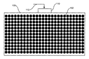
まず、図1A〜図1Dを参照する。これらは、本発明のいくつかの実施形態による全体照明および伝達用の機器の異なるモードを示す正面図である。例えば、図1Aを参照すると、固体発光パネル100は、複数の固体発光体102を含み得る。図1Bに示すように、固体発光体102を選択的にアドレス指定かつ/または制御して、1つまたは複数の固体発光体102Aに電圧を加え、1つまたは複数の固体発光体102Bには電圧を加えないようにすることができる。
First, reference is made to FIGS. 1A to 1D. These are front views showing different modes of the overall illumination and transmission device according to some embodiments of the present invention. For example, referring to FIG. 1A, the solid state
いくつかの実施形態では、すべての固体発光体102を、ほぼ同じ主波長で発光するように構成し得る。例えば、これらの固体発光体は、波長変換蛍光体を被覆した青色発光LEDを含む白色LEDランプとし得る。この波長変換蛍光体は、LEDから出た青色光の一部を黄色光に変換する。得られた光は、青色光と黄色光の混合光であり、観察者には白色に見えることがある。例えば、照明モードの固体発光パネル100は、すべての固体発光体102が電圧を加えられた固体発光体102Aであり、それによって近接区域を全体的に照明するように構成される。いくつかの実施形態では、複数の固体発光体102の一部に選択的に電圧を加え、かつ/または、固体発光体102を低電流レベルで動作させることによって発光レベルを変えることができる。
In some embodiments, all solid state
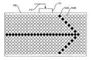
いくつかの実施形態では、固体発光体102の一部を選択的に動作させることによって情報を伝達し得る。例えば、図1Bに示すように、「EXIT」の文字を表す固体発光体102の一部を選択的に動作させることによって出口を示すために、固体発光パネル100は伝達モードを取り得る。同様に、図1Cに示すように、固体発光体102の一部を選択的に動作させて矢印の像を形成することによって、進むべき経路を示すことができる。
In some embodiments, information may be communicated by selectively operating portions of the solid
固体発光パネル100は、例えば、特別なイベントおよび/または活動を示す商業的な状況でも使用し得る。例えば、図1Dに示すように、固体発光体102の一部を選択的に動作させて、中でも「SALE」などの文字を表すことによって商業イベントを示すことができる。図示しないが、固体発光パネル100は、他にも、企業、産業、施設、運送、および/または教育などの環境で使用して、中でもイベントの開始および終了の時間および/または状況を指示することができる。例えば、教育環境では、授業の開始および終了の時間および/または状況を表示することができる。同様に、例えばバスおよび/または飛行機などの大量輸送機関で警報および/または他の情報を伝達することができる。
The solid
いくつかの実施形態では、固体発光体102は、第1の主波長で発光するように構成された第1の部分の固体発光体102と、第2の主波長で発光するように構成された第2の部分の固体発光体102とを含み得る。このように、第1の部分の固体発光体は全体照明を提供するように動作させ、第2の部分は情報を伝達するように動作させることができる。例えば、第1の部分の固体発光体102はほぼ白色光を出射して全体照明を提供するように構成し、第2の部分の固体発光体102はほぼ赤色光を出射して、例えば、中でも、火災、地震、天気状況、および/または他の危険な状態および/または事象などの状態を指示するように構成し得る。さらに、第2の部分の固体発光体102は、画像による追加の情報を伝達するように選択的に動作させることができる。
In some embodiments, the solid
いくつかの実施形態では、固体発光体102は、全体照明を行う通常動作下でほぼ白色光を提供し得る個々にアドレス指定可能なマルチカラー発光器として構成し得る。伝達モードでは、このマルチカラー発光器は、中でも赤色光を発光するように制御し得る。このように、文字および画像に基づく伝達に加えて、色分けした伝達も可能である。
In some embodiments, the solid
動きのない文字、画像、および/または色に加えて、例えば、動きの視覚効果を作りだす画像列に対応して固体発光体102を動的に制御し得る。いくつかの実施形態では、第1の部分の固体発光体102は照明を提供するように動作させ、第2の部分の固体発光体102は情報を伝達するように動作させるハイブリッドモードで、固体発光パネル100を動作させることができる。
In addition to non-motion characters, images, and / or colors, for example, the solid
固体発光パネル100は、複数の固体発光体102を制御するように構成されたマルチモード発光パネルコントローラ110も含み得る。マルチモード発光パネルコントローラ110は、入力信号112を受け取るように構成し得る。マルチモード発光パネルコントローラ110は、入力信号112に応答して照明モードおよび/または伝達モードを選択し得る。入力信号112は、中でも、警報、緊急事態、定期的なイベント、手動入力、および/または環境センサに応答して入力信号112を送出し得る外部システムなどから受け取ることができる。
The solid state
次に、図2を参照する。図2は、本発明のいくつかの実施形態による機器を示すブロック図である。マルチモード照明機器200は、固体発光パネル210を備える。この固体発光パネルは、マルチモード発光パネルコントローラ220によって制御し得る複数の固体発光体を含み得る。マルチモード発光パネルコントローラ220は、ある区域を照明する第1のモードと、この区域内でメッセージを伝達する第2のモードとで固体発光体を制御するように構成し得る。いくつかの実施形態では、これらの固体発光体は、第1のモードに対応する複数の第1の色の発光器と、第2のモードに対応する複数の第2の色の発光器とを含み得る。
Reference is now made to FIG. FIG. 2 is a block diagram illustrating an apparatus according to some embodiments of the invention. The
いくつかの実施形態では、これら固体発光体の少なくとも一部は、第1のモードではほぼ白色光を出射し、第2のモードではほぼ非白色光を出射するように構成し得る個々にアドレス指定可能なマルチカラー固体発光体を含み得る。いくつかの実施形態では、これらの固体発光体は、第1のモードでは照明を提供するように動作させることができる。いくつかの実施形態では、これらの固体発光体は、第2のモードでは情報を伝える画像を表示するように選択的に動作させることができる。例えば、こうした画像は、特定の固体発光体をアレイ状に選択することによって形成し得る文字および/または記号を含み得る。 In some embodiments, at least some of these solid state light emitters can be individually addressed that can be configured to emit substantially white light in the first mode and substantially non-white light in the second mode. Possible multicolor solid state light emitters may be included. In some embodiments, these solid state light emitters can be operated to provide illumination in the first mode. In some embodiments, these solid state light emitters can be selectively operated to display an image carrying information in the second mode. For example, such images can include letters and / or symbols that can be formed by selecting particular solid state light emitters in an array.
いくつかの実施形態では、マルチモード発光パネルコントローラ220は、入力信号を受け取るように構成された入力モジュール222を含み得る。マルチモード発光パネルコントローラ220は、入力信号に応答して第1のモードおよび/または第2のモードを選択するように構成し得る。いくつかの実施形態では、入力信号は、外部システム230によって生成し得る。例えば、外部システム230は、イベント、警報、および/またはスケジュールに基づくものとし得る。
In some embodiments, the multi-mode
いくつかの実施形態では、入力モジュール222は、環境センサ240から入力信号を受け取るように構成し得る。例えば、環境センサ240を使用して、警報および/または緊急事態の場合に温度および/または煙を感知することができる。このような状況では、マルチモード発光パネルコントローラ220は、代替出口経路に対応する情報などを代わりに伝達するように構成し得る。いくつかの実施形態では、環境センサ240は、人がいるかいないかに対応する特定の伝達を開始するのに使用し得る人感知センサとし得る。例えば、商業的な状況では、店舗にいる顧客が特定の区域に立ち入ったとき、例えば特売、特価品、および/または値引きなどの商業的なイベントを伝達し得る。環境センサ240は、入力モジュール222に信号を提供することに加えて、外部システム230に信号を提供することもでき、次いで、外部システム230は、マルチモード発光パネルコントローラ220に入力信号を送信することができる。
In some embodiments, the
ここで図3を参照する。図3は、本発明のいくつかの実施形態による動作を示すブロック図である。動作には、第1の色および第2の色の固体発光体を含む固体発光パネルによってある区域を照明すること(ブロック310)が含まれる。いくつかの実施形態では、照明することは、すべての第1の色および第2の色の固体発光体を動作させることによって実施し得る。 Reference is now made to FIG. FIG. 3 is a block diagram illustrating operations according to some embodiments of the present invention. Operation includes illuminating an area with a solid state light emitting panel that includes solid state light emitters of a first color and a second color (block 310). In some embodiments, illuminating may be performed by operating all the first and second color solid state light emitters.
いくつかの実施形態では、第1の色の固体発光体は、ほぼ白色光を出力することができる。例えば、いくつかの実施形態では、第1の色の固体発光体は、放出された光の一部を黄色光に変換する波長変換蛍光体で被覆された青色発光LEDであると規定し得る。いくつかの実施形態では、第1の色の固体発光体は、それぞれ照明モードで白色光を提供するように制御し得るマルチカラー発光器を含むと規定し得る。 In some embodiments, the first color solid state light emitter can output substantially white light. For example, in some embodiments, the first color solid state light emitter may be defined as a blue light emitting LED coated with a wavelength converting phosphor that converts a portion of the emitted light to yellow light. In some embodiments, the first color solid state light emitters may each be defined as including multicolor light emitters that can be controlled to provide white light in an illumination mode.
いくつかの実施形態では、第2の色の固体発光体は、ほぼ非白色光を出力し得る。例えば、赤色発光LEDは、第1の色の固体発光体と組み合わせて使用して、全体の光出力における赤色光のエネルギーを高くし得る。 In some embodiments, the second color solid state light emitter may output substantially non-white light. For example, a red light emitting LED can be used in combination with a first color solid state light emitter to increase the energy of red light in the overall light output.
動作には、第2の色の固体発光体を選択的に動作させることによって固体発光パネルを介してメッセージを伝達すること(ブロック320)が含まれることもある。いくつかの実施形態では、文字および/または記号を含み得る画像を使用して1つまたは複数のメッセージを伝達するように第2の色の固体発光体の一部を指定することができる。例えば、「EXIT」の文字および/または矢印記号を表示して出口および/または脱出情報を伝達するように第2の色の固体発光体の一部を選択することができる。 The operation may include communicating a message through the solid state light emitting panel by selectively operating the second color solid state light emitter (block 320). In some embodiments, a portion of the second color solid state light emitter may be designated to convey one or more messages using an image that may include letters and / or symbols. For example, a portion of the second color solid state light emitter can be selected to display the letters “EXIT” and / or an arrow symbol to convey exit and / or exit information.
いくつかの実施形態では、第2の色の固体発光体をそれぞれ個々にアドレス指定可能にし、選択的に動作させて、文字、画像、および/または色によるメッセージを伝達することができる。例えば、火災および/または他の緊急の状態では、赤色に対応する主波長で発光するようにすべての第2の色の固体発光体を動作させることができる。いくつかの実施形態では、色分けを利用してこうしたメッセージを伝達し得る。例えば、赤色出力は、火災などの緊急事態を示すことが知られている。 In some embodiments, each of the second color solid state light emitters can be individually addressed and selectively actuated to convey text, image, and / or color messages. For example, in a fire and / or other emergency situation, all second color solid state light emitters can be operated to emit light at a dominant wavelength corresponding to red. In some embodiments, color coding may be used to communicate such messages. For example, red output is known to indicate an emergency such as a fire.
いくつかの実施形態による動作は、伝達モード信号を受け取り、この信号に応答してメッセージを表示することを含み得る(ブロック330)。例えば、いくつかの実施形態は、緊急の状態に対応する警報信号を受け取り、出口経路および/またはその状態に対応するメッセージを伝達するように構成し得る。いくつかの実施形態では、商業的な状況で伝達モード信号を使用して、潜在的な顧客に情報を提供し、かつ/または商業的な環境における特定の特徴に注意を引きつけることができる。1つの装置に全体発光機能および様々な伝達機能を備えることによって、そうしないと独立した機能になるもののために別々の装備を備えることを避けることができる。 Operations according to some embodiments may include receiving a transmission mode signal and displaying a message in response to the signal (block 330). For example, some embodiments may be configured to receive an alarm signal corresponding to an emergency condition and communicate a message corresponding to the exit path and / or the condition. In some embodiments, transmission mode signals can be used in commercial situations to provide information to potential customers and / or to attract particular features in a commercial environment. By providing an overall light emitting function and various transmission functions in one device, it is possible to avoid having separate equipment for what would otherwise be an independent function.
次に、図4を参照する。図4は、本発明のいくつかの実施形態による伝達モードにおける複数のマルチモード機器を示すブロック図である。各マルチモード機器400は、複数の固体発光体412を含む固体発光パネル410を含み得る。伝達モードでは、記号および/または文字を使用した1つまたは複数のメッセージを伝達するように固体発光体412を選択的に動作させることができる。
Reference is now made to FIG. FIG. 4 is a block diagram illustrating a plurality of multi-mode devices in transmission mode according to some embodiments of the present invention. Each
固体発光体412は、マルチモード発光パネルコントローラ420を介して選択的に動作させることができる。いくつかの実施形態では、マルチモード発光パネルコントローラ420は、受け取った入力信号に応答して固体発光体412を選択的に動作させるように構成し得る。いくつかの実施形態では、複数のマルチモード機器400を互いに組み合わせて使用して、伝達を連係して行うことができる。例えば、固体発光パネル410はそれぞれ、出口および/または脱出経路に沿った異なる場所に対応する異なるメッセージを伝達し得る。
The solid
いくつかの実施形態では、マルチモード発光パネルコントローラ420は、中央コントローラおよび/または外部のシステムおよび/または装置から入力信号を受け取り、受け取った入力信号に応答してメッセージを表示するように構成し得る。いくつかの実施形態では、マルチモード発光パネルコントローラ420は、離れた環境状態センサからデータを受け取り、受け取ったデータに応答してメッセージを伝達するように構成し得る。いくつかの実施形態では、各マルチモード機器400のマルチモード発光パネルコントローラ420は、固体発光体412を分散制御することができ、中央コントローラなしで機能することができる。
In some embodiments, the multi-mode
次に、図5を参照する。図5は、本発明の別の実施形態による複数のマルチモード機器を示すブロック図である。各マルチモード機器500は、複数の固体発光体512を含む固体発光パネル510を含み得る。照明モードでは、マルチモード機器500に近接した区域に全体照明を提供するように固体発光体512を動作させることができる。例えば、最大電流および/または最大デューティサイクルですべての固体発光体512を駆動することによって最も明るい照明を提供し得る。固体発光体512を一部だけ駆動することによって、かつ/または最大値よりも低い電流および/またはデューティサイクルで固体発光体512を駆動することによって減光機能を提供することができる。
Reference is now made to FIG. FIG. 5 is a block diagram illustrating a plurality of multi-mode devices according to another embodiment of the present invention. Each
伝達モードでは、記号および/または文字を使用して1つまたは複数のメッセージを伝達するように固体発光体512を選択的に動作させることができる。各マルチモード機器500は、固体発光体512を選択的に動作させるように構成されたマルチモード発光パネルコントローラ520を含み得る。いくつかの実施形態では、マルチモード発光パネルコントローラ520は、入力信号530を受け取るように構成された入力モジュールを含み得る。いくつかの実施形態では、入力信号530は、すべてのマルチモード機器500に共通の信号とし得る。いくつかの実施形態では、入力信号530は、各マルチモード機器500を他とは独立に選択的にアドレス指定し得る。いくつかの実施形態では、マルチモード発光パネルコントローラ520は、固体発光体512に電流を選択的に流し、中央コントローラから制御データを受け取るように構成されたドライバを含み得る。
In the transfer mode, the solid
次に、図6を参照する。図6は、本発明のいくつかの実施形態による複数のマルチカラーマルチモード固体発光パネルを示すブロック図である。マルチカラーマルチモード固体発光パネル600は、それぞれのマルチモード発光パネルコントローラ610によって駆動することができ、それによって、第1のモードで全体照明を提供し、第2のモードで1つまたは複数のメッセージを伝達し得る。
Reference is now made to FIG. FIG. 6 is a block diagram illustrating a plurality of multi-color multi-mode solid state light emitting panels according to some embodiments of the present invention. The multi-color multi-mode solid
各マルチカラーマルチモード固体発光パネル600は、マルチカラー固体発光体612を含み得る。マルチカラー固体発光体612は、第1のモードでほぼ白色光を出射し、第2のモードで非白色光を出射するように構成し得る。第2のモードでは、情報を伝える画像を表示するようにマルチカラー固体発光体612を選択的に動作させることができる。例えば、こうした画像は、情報を伝える文字および/または1つまたは複数の記号を含み得る。いくつかの実施形態では、一連の複数画像を使用して動的な発光構成を生成し得る。
Each multicolor multimode solid state
マルチカラー固体発光体612は、個々のカラーLEDチップ604〜607を搭載し得る基板608を含み得る。例えば、ほぼ赤色のLED604、ほぼ青色のLED607、および2つのほぼ緑色のLED605、606を基板608に搭載することができる。個々のカラーLEDチップ604〜607はそれぞれ個々にアドレス指定可能とし得る。LEDチップ604〜607を選択的に動作させることによって発光色を制御し得る。例えば、ほぼ白色光が生成されるようにすべてのLEDチップ604〜607を駆動することができる。
The multi-color solid
マルチモード発光パネルコントローラ610は、中央発光パネルコントローラ620から入力信号624を受け取るように構成し得る。このようにして、複数の発光パネルは、連係して使用される。いくつかの実施形態では、環境状態センサ640を使用して、中央発光パネルコントローラ620および/またはマルチモード発光パネルコントローラ610に環境情報信号を提供し得る。例えば、商業的な状況では、環境状態センサ640を使用して、潜在的な顧客が近くにいることを検出することができ、こうした顧客は、その後、発光パネルの1つまたは複数を介してメッセージを見ることができる。
Multi-mode
次に、図7を参照する。図7は、本発明のいくつかの実施形態による両面マルチモード発光機器の側面断面図である。マルチモード発光機器700は、複数の固体発光体702を含む両面固体発光パネル710を備える。いくつかの実施形態では、両面固体発光パネル710は、第1の方向に光を出射するように位置決めされた第1の部分の固体発光体702Aと、第1の方向と異なる第2の方向に光を出射するように位置決めされた第2の部分の固体発光体702Bとを含む。
Reference is now made to FIG. FIG. 7 is a side cross-sectional view of a double-sided multimode light emitting device according to some embodiments of the present invention. The multi-mode
マルチモード発光機器700はさらに、固体発光体702Aおよび702Bを制御するように構成されたマルチモード発光パネルコントローラ720を備える。いくつかの実施形態では、マルチモード発光パネルコントローラ720は、中でも、中央コントローラ、外部のシステムおよび/または装置、および/または環境センサから入力信号730を受け取るように構成し得る。いくつかの実施形態では、マルチモード発光機器700は、マルチモード発光パネルコントローラ720で受け取った入力信号730に応答して1つまたは複数のモードで動作するように構成される。例えば、マルチモード発光機器700は、入力信号730に応答して照明モードおよび/または伝達モードで選択的に動作し得る。
Multimode
いくつかの実施形態は、第1の部分の固体発光体702Aが、波長変換蛍光体で被覆された青色発光LEDおよび/または1つまたは複数の主波長で発光するように構成されたLEDを含むと規定し得る。いくつかの実施形態では、第2の部分の固体発光体702Bは、広いスペクトルの光を出射するように構成された赤、緑、および青のマルチカラー発光器を含み得る。いくつかの実施形態では、第1の部分の固体発光体702Aは照明モードで動作し、第2の部分の固体発光体702Bは伝達モードで動作し得る。いくつかの実施形態では、第1の部分の固体発光体702Aおよび第2の部分の固体発光体702Bはともに、照明モードおよび/または伝達モードのいずれでも、あるいはそのいずれかで動作し得る。
Some embodiments include a first portion of the solid state
次に、図8Aおよび図8Bを参照する。図8Aおよび図8Bは、本発明のいくつかの実施形態による全体照明および伝達用の機器の異なるモードを示す正面図である。例えば、図8Aを参照すると、固体発光パネル800は、複数の第1の色の固体発光体802Aおよび複数の第2の色の固体発光体802Bを含み得る。
Reference is now made to FIGS. 8A and 8B. 8A and 8B are front views illustrating different modes of the overall illumination and transmission device according to some embodiments of the present invention. For example, referring to FIG. 8A, the solid state
いくつかの実施形態では、複数の第1の色の固体発光体802Aは、波長変換蛍光体で被覆された青色発光LEDを含み得る。得られる光は、青色光と黄色光の組合せであり、観察者には白色に見えることがある。しかし、このような構成によって生成された光は白色に見えることがある一方で、光のスペクトルが制限されているために、このような光に照明された物体は自然な色合いを有するように見えないことがある。例えば、このような光は可視スペクトルの赤色部分のエネルギーが低いことがあるので、物体がもつ赤色はこのような光によってうまく照明されないことがある。その結果、この物体は、このような光源下で観察すると、不自然な色合いを有するように見えることがある。
In some embodiments, the plurality of first color solid state
いくつかの実施形態では、複数の第2の色の固体発光体802Bは、赤色発光LEDを含み得る。このように、第1の色の固体発光体802Aと第2の色の固体発光体802Bとの組合せによって得られた照明では、可視スペクトルの赤色部分のエネルギーが高くなることに関連してスペクトルのもつ暖かさが増加することがある。
In some embodiments, the plurality of second color solid state
図8Bに示すように、第2の色の固体発光体802Bはその一部を、情報を伝えるように構成された画像を形成するように選択的に動作させることができる。いくつかの実施形態では、第2の色の固体発光体802Bを使用して、色分けおよび/または画像を介してメッセージを伝達することができる。例えば、赤色発光LEDだけを動作させることにより、中でも、火災などの緊急の状態を示すことができる。このように、第1の色の固体発光体802Aおよび第2の色の固体発光体802Bを選択的に動作させることによって、照明モードでは広いスペクトルの光を提供することができ、伝達モードでは情報を伝え、かつ/または伝達することができる。
As shown in FIG. 8B, a portion of the second color solid
いくつかの実施形態では、第1の色の固体発光体802Aおよび/または第2の色の固体発光体802Bの一部に選択的に電圧を加えることによって、かつ/または第1の色の固体発光体802Aおよび/または第2の色の固体発光体802Bを低電流レベルで動作させることによって、発光レベルを変えることができる。
In some embodiments, by selectively applying a voltage to a portion of the first color solid state
次に、図9を参照する。図9は、本発明のいくつかの実施形態による、類似の装置と協調して動作し得るマルチモード機器を示すブロック図である。この機器は、複数の固体発光体912を含み得る固体発光パネル900および入力モジュール910を含み得る。入力モジュール910は、発光パネル群コントローラ920から入力信号を受け取るように構成し得る。発光パネル群コントローラ920は、複数の固体発光パネル900を協調して制御するように構成し得る。
Reference is now made to FIG. FIG. 9 is a block diagram illustrating a multi-mode device that can operate in concert with similar devices, according to some embodiments of the invention. The apparatus can include a solid state
発光パネル群コントローラ920は、照明を提供する第1のモードおよび情報を伝達する第2のモードで複数の固体発光パネル900を協調して制御するように構成し得る。いくつかの実施形態では、固体発光パネル900の少なくとも1つは、第1のモードに対応する複数の第1の色の発光器および第2のモードに対応する複数の第2の色の発光器を含み得る。例えば、第1の色の発光器は照明用にほぼ白色光を出射するように構成することができ、第2の色の発光器は赤色に対応する主波長の光を出射するように構成することができる。このように、第1のモードでは、すべての固体発光パネル900は第1の色の発光器を使用して動作し得る。
The light emitting
第2のモードでは、緊急脱出経路に対応する固体発光パネル900は、第1の色の発光器を使用して動作させ、経路を示すためには使用しない他の固体発光パネル900は、第2の色の発光器を使用して動作させることができる。いくつかの実施形態では、第2のモードでは固体発光パネル900を選択的に動作させると規定し得る。例えば、経路および/または目的地に対応する固体発光パネル900は動作させるが、経路および/または目的地を示すためには使用しない他の固体発光パネル900には電圧を加えないことができる。
In the second mode, the solid
いくつかの実施形態では、発光パネル群コントローラ920は、第2のモードに対応する動的なやり方で複数の固体発光パネル900を協調して制御するように構成し得る。例えば、経路および/または目的地に対応する固体発光パネル900を、ある方向を指すように順に動作させ、それによって脱出経路の方向を示すことができる。
In some embodiments, the lighting
次に、図10を参照する。図10は、本発明のいくつかの実施形態による動作を示すブロック図である。発光パネル群コントローラから受け取った入力信号に応答して、第1のモードで複数の固体発光パネルを使用してある区域を照明することができる(ブロック1010)。第2のモードで複数の固体発光パネルの一部を選択的に動作させることによって情報を伝達することができる(ブロック1020)。いくつかの実施形態では、複数の固体発光パネルを選択的に動作させて所望の経路および/または目的地を示すことができる。例えば、緊急の状態では、複数の固体発光パネルのいくつかを選択的に動作させて脱出経路を照明し、それによって脱出経路を示すことができる。いくつかの実施形態では、固体発光パネルの選択的な動作は、経路だけでなく脱出方向を示し得る動的な動作を含み得る。いくつかの実施形態では、固体発光パネルは、発光動作および/または伝達動作を補い、かつ/または強化するために選択的に動作させることができるマルチカラー発光器を含み得ると規定し得る。例えば、これらのマルチカラー発光器は、第1のモードでほぼ白色光を出射し、第2のモードでほぼ非白色光を出射するように動作させることができる。いくつかの実施形態では、他の固体発光パネルに対して相対的に異なる色、および/または、動的かつ/または静的な動作を用いて、例えば出口ドアなどの目的地を明確に示すことができる。 Reference is now made to FIG. FIG. 10 is a block diagram illustrating operations according to some embodiments of the present invention. In response to an input signal received from the lighting panel group controller, an area may be illuminated using a plurality of solid state lighting panels in a first mode (block 1010). Information may be communicated by selectively operating a portion of the plurality of solid state light emitting panels in the second mode (block 1020). In some embodiments, multiple solid state lighting panels can be selectively operated to indicate a desired path and / or destination. For example, in an emergency situation, some of the plurality of solid state lighting panels can be selectively operated to illuminate the escape path, thereby indicating the escape path. In some embodiments, the selective operation of the solid state lighting panel may include a dynamic operation that may indicate the escape direction as well as the path. In some embodiments, it may be defined that a solid state lighting panel may include multi-color light emitters that can be selectively operated to supplement and / or enhance light emitting and / or transmitting operations. For example, these multi-color light emitters can be operated to emit substantially white light in the first mode and substantially non-white light in the second mode. In some embodiments, a different color and / or dynamic and / or static behavior relative to other solid state lighting panels is used to clearly indicate a destination, such as an exit door, for example. Can do.
いくつかの実施形態では、情報の伝達は、発光パネル群コントローラから固体発光パネルが受け取った入力信号に応答する第2のモードに対応し得る。いくつかの実施形態では、この発光パネル群コントローラは、例えば、中でも、環境制御システム、通信システム、データネットワーク、および/または警報システムなどのビルディングブロック制御システムを備える。いくつかの実施形態では、入力信号は、環境センサからのデータに応答して生成し得る(ブロック1030)。環境センサのいくつかの実施形態には、中でも、煙センサ、火災センサ、保安センサ、天候センサ、および/または他の緊急状態センサが含まれる。 In some embodiments, the communication of information may correspond to a second mode that is responsive to an input signal received by the solid state lighting panel from the lighting panel group controller. In some embodiments, the lighting panel group controller comprises a building block control system such as, for example, an environmental control system, a communication system, a data network, and / or an alarm system, among others. In some embodiments, the input signal may be generated in response to data from the environmental sensor (block 1030). Some embodiments of environmental sensors include, among other things, smoke sensors, fire sensors, security sensors, weather sensors, and / or other emergency conditions sensors.
次に、図11を参照する。図11は、本発明のいくつかの実施形態による本明細書で説明したシステムの平面図を、その応用例と合わせて示すブロック図である。照明および伝達用のシステムは、人のスペースにそれぞれ離して配置され、発光パネル群コントローラ1130が送出した入力信号1132に応答して協調して動作する複数の固体発光パネル1120A〜Fを含み得る。いくつかの実施形態では、固体発光パネル1120A〜Fは、第1のモードで照明を提供し、第2のモードで情報を伝達するように協調して動作させることができる。
Reference is now made to FIG. FIG. 11 is a block diagram illustrating a top view of the system described herein, along with its applications, according to some embodiments of the present invention. The lighting and transmission system may include a plurality of solid state
固体発光パネル1120A〜Fは、例えば、人が占有するように設計されたオフィス、実験室、製造区域、販売、および/または他のタイプのスペースなど、人のスペース1110を照明するように構成し得る。人のスペース1110は、例えば、中でも、小部屋などの特定のサブスペース1114A、1114Bを画定するように構成された仕切りおよび/または壁など、スペース分割体1116を含み得る。人のスペース1110は、脱出用出口1112を含み得る。
The solid
第1のモードでは、すべての固体発光パネル1120A〜Fは、人のスペース1110全体にわたって比較的均一な照明レベルを提供するように動作させることができる。第2のモードでは、固体発光パネル1120A〜Fのうちいくつかを、人のスペース1110にいる人に情報を伝達するように選択的に動作させることができる。例えば、固体発光パネル1120B、1120D、および1120Fは、第2のモードで、出口1112に至る通路の場所をそこにいる人に伝達するように動作させることができる。このように、例えば緊急の状態の間中、固体発光パネル1120A、1120C、および1120Eは動作させないが、通路に近い固体発光パネル1120B、1120D、および1120Fを動作させることによって、そこにいる人を通路に誘導することができる。
In the first mode, all of the solid
いくつかの実施形態では、固体発光パネル1120B、1120D、および1120Fは、出口1112に向かう点滅列を提供するように動的に動作させることができる。いくつかの実施形態では、固体発光パネル1120Bは連続的に動作させ、固体発光パネル1120Dおよび1120Fは、出口1112に行き着くのに必要な移動方向を示すように動的に動作させることができると規定し得る。いくつかの実施形態では、固体発光パネル1120A〜Fのうちいくつかは、第2のモードでほぼ非白色光を提供するように選択的に動作させることができる。例えば、固体発光パネル1120A、1120C、および1120Eは、赤色に対応する主波長を含む光を出射するように動作させることができる。いくつかの実施形態では、発光色は、固体発光パネル1120A〜Fを協調して動作させることによって、伝達中の情報の状態の性質に特定なものとし得る。例えば、青色に対応する主波長を含む光を出射させて、安全に関連する状態および/または事象を示すことができる。同様に、赤色に対応する主波長を含む光を出射させて、火災に関連する状態および/または事象を示すことができる。
In some embodiments, the solid
発光パネル群コントローラ1130は、ビルディングブロック制御システムを含み得る。いくつかの実施形態では、発光パネル群コントローラ1130は、入力信号を生成し、かつ/または(図示しない)環境状態センサに応答して入力信号の状態を変化させるように構成し得る。いくつかの実施形態では、発光パネル群コントローラ1130は、固体発光パネル1120A〜Fに一連の入力信号を送出することによって、第2のモードで情報を動的に伝達するように構成し得る。
The light emission
いくつかの実施形態では、固体発光パネル1120A〜F内の発光器は、個々にアドレス可能とすることもできるし、群ごとにアドレス可能とすることもでき、かつ/または個々にはアドレス可能でないようにすることもできる。例えば、固体発光パネル1120A〜Fは、1つの信号および/または入力に応答して集合的に動作する発光器に限定することができる。
In some embodiments, the light emitters in the solid state
以上、本発明の典型的な実施形態を図面および明細書を用いて開示した。特定の用語を用いたが、これらは、一般的かつ説明的な意味でのみ用いており、制限を課すためのものではない。本発明の範囲は添付の特許請求の範囲に記載する。 The exemplary embodiments of the present invention have been disclosed with reference to the drawings and the specification. Although specific terms are used, they are used in a general and descriptive sense only and are not intended to impose limitations. The scope of the invention is set forth in the appended claims.
Claims (20)
前記入力信号に応答して前記複数の固体発光パネルの第1の部分を選択的に動作させることによって前記複数の固体発光パネルを介して情報を伝達することとを含むことを特徴とする方法。 Illuminating an area by operating in a first mode a plurality of solid state light emitting panels, each spaced apart in a person's space, in response to an input signal received from a light emitting panel group controller;
Transmitting information through the plurality of solid state light emitting panels by selectively operating a first portion of the plurality of solid state light emitting panels in response to the input signal.
人のスペースにそれぞれ離して配置された複数の固体発光パネルを備え、前記複数の固体発光パネルは、複数の固体発光体を含み、前記複数の固体発光パネルで受け取った入力信号に応答して、第1のモードで照明を提供し、第2のモードで情報を伝達するように構成され、前記システムはさらに、
前記複数の固体発光パネルの少なくとも1つに前記入力信号を送出するように構成された発光パネル群コントローラを備えることを特徴とするシステム。 A system for lighting and transmission,
A plurality of solid state light emitting panels each disposed separately in a human space, the plurality of solid state light emitting panels including a plurality of solid state light emitters, in response to input signals received by the plurality of solid state light emitting panels; Configured to provide illumination in a first mode and communicate information in a second mode, the system further comprising:
A system comprising: a light emitting panel group controller configured to send the input signal to at least one of the plurality of solid state light emitting panels.
Applications Claiming Priority (1)
| Application Number | Priority Date | Filing Date | Title |
|---|---|---|---|
| US12/056,431 US9930756B2 (en) | 2008-03-27 | 2008-03-27 | Apparatus, methods and systems for providing lighting and communication |
Publications (1)
| Publication Number | Publication Date |
|---|---|
| JP2009282502A true JP2009282502A (en) | 2009-12-03 |
Family
ID=40795050
Family Applications (1)
| Application Number | Title | Priority Date | Filing Date |
|---|---|---|---|
| JP2009074726A Pending JP2009282502A (en) | 2008-03-27 | 2009-03-25 | Apparatus, methods and systems for providing lighting and communication |
Country Status (3)
| Country | Link |
|---|---|
| US (3) | US9930756B2 (en) |
| EP (3) | EP3422820B1 (en) |
| JP (1) | JP2009282502A (en) |
Cited By (1)
| Publication number | Priority date | Publication date | Assignee | Title |
|---|---|---|---|---|
| JP2017123008A (en) * | 2016-01-06 | 2017-07-13 | 三菱電機株式会社 | Lighting device, lighting control system, and evacuation guidance system |
Families Citing this family (22)
| Publication number | Priority date | Publication date | Assignee | Title |
|---|---|---|---|---|
| US8653984B2 (en) * | 2008-10-24 | 2014-02-18 | Ilumisys, Inc. | Integration of LED lighting control with emergency notification systems |
| EP2583269A4 (en) * | 2010-06-17 | 2014-12-31 | Light Bohrd Llc | Systems and methods for luminescent display |
| US20120283878A1 (en) * | 2011-05-06 | 2012-11-08 | Bruce Richard Roberts | Controller and solid state lighting device for large area applications |
| US11792898B2 (en) * | 2012-07-01 | 2023-10-17 | Ideal Industries Lighting Llc | Enhanced fixtures for area lighting |
| US11160148B2 (en) | 2017-06-13 | 2021-10-26 | Ideal Industries Lighting Llc | Adaptive area lamp |
| KR20140110593A (en) * | 2013-03-08 | 2014-09-17 | 현대자동차주식회사 | Vehicle having lamp |
| US10531545B2 (en) | 2014-08-11 | 2020-01-07 | RAB Lighting Inc. | Commissioning a configurable user control device for a lighting control system |
| US10497337B2 (en) | 2015-07-17 | 2019-12-03 | Abl Ip Holding Llc | Systems and methods to provide configuration data to a software configurable lighting device |
| EP3325400A1 (en) * | 2015-07-17 | 2018-05-30 | ABL IP Holding LLC | Software configurable lighting device |
| US10412800B1 (en) * | 2016-04-07 | 2019-09-10 | Christopher S. Beattie | Vehicle LED display system |
| US10529696B2 (en) | 2016-04-12 | 2020-01-07 | Cree, Inc. | High density pixelated LED and devices and methods thereof |
| US10734363B2 (en) | 2017-08-03 | 2020-08-04 | Cree, Inc. | High density pixelated-LED chips and chip array devices |
| WO2019028314A1 (en) | 2017-08-03 | 2019-02-07 | Cree, Inc. | High density pixelated-led chips and chip array devices, and fabrication methods |
| US10529773B2 (en) | 2018-02-14 | 2020-01-07 | Cree, Inc. | Solid state lighting devices with opposing emission directions |
| US10991215B2 (en) | 2018-03-20 | 2021-04-27 | Ideal Industries Lighting Llc | Intelligent signage |
| JP2020052529A (en) * | 2018-09-25 | 2020-04-02 | 京セラドキュメントソリューションズ株式会社 | Name plate |
| US10903265B2 (en) | 2018-12-21 | 2021-01-26 | Cree, Inc. | Pixelated-LED chips and chip array devices, and fabrication methods |
| WO2021087109A1 (en) | 2019-10-29 | 2021-05-06 | Cree, Inc. | Texturing for high density pixelated-led chips |
| DE102020126196A1 (en) * | 2020-10-07 | 2022-04-07 | Voith Patent Gmbh | signaling system |
| US11437548B2 (en) | 2020-10-23 | 2022-09-06 | Creeled, Inc. | Pixelated-LED chips with inter-pixel underfill materials, and fabrication methods |
| CN112542104A (en) * | 2020-12-30 | 2021-03-23 | 苏州佩林网络科技有限公司 | Intelligent lamp and control method thereof |
| WO2023050399A1 (en) * | 2021-09-30 | 2023-04-06 | 华为技术有限公司 | Display control method and apparatus and terminal device |
Citations (10)
| Publication number | Priority date | Publication date | Assignee | Title |
|---|---|---|---|---|
| JPS4890694A (en) * | 1972-03-07 | 1973-11-26 | ||
| JPS59186092A (en) * | 1983-04-06 | 1984-10-22 | 株式会社ウエルウツド | Display unit |
| JPH03222202A (en) * | 1990-01-26 | 1991-10-01 | Matsushita Electric Works Ltd | Guiding device |
| JPH10326382A (en) * | 1997-05-27 | 1998-12-08 | Matsushita Electric Works Ltd | Refuge guide device |
| WO2002016826A1 (en) * | 2000-08-24 | 2002-02-28 | Simon Grant Rozenberg | Improvements in lamps, luminaires and lighting systems |
| JP2006003750A (en) * | 2004-06-18 | 2006-01-05 | Sanyo Electric Co Ltd | Led lighting fixture |
| JP2007171702A (en) * | 2005-12-23 | 2007-07-05 | Mitsumi Electric Co Ltd | Wireless light emitting display apparatus |
| JP2007248687A (en) * | 2006-03-15 | 2007-09-27 | Megachips System Solutions Inc | Display system based on illuminator |
| JP2008152080A (en) * | 2006-12-19 | 2008-07-03 | Nichia Chem Ind Ltd | Illumination apparatus |
| JP2008270212A (en) * | 2007-04-17 | 2008-11-06 | Cree Inc | Light emitting diode-based emergency lighting method and device |
Family Cites Families (9)
| Publication number | Priority date | Publication date | Assignee | Title |
|---|---|---|---|---|
| US7385359B2 (en) * | 1997-08-26 | 2008-06-10 | Philips Solid-State Lighting Solutions, Inc. | Information systems |
| US6380865B1 (en) * | 1999-04-06 | 2002-04-30 | 911 Emergency Products, Inc. | Replacement led lamp assembly and modulated power intensity for light source |
| US6317058B1 (en) * | 1999-09-15 | 2001-11-13 | Jerome H. Lemelson | Intelligent traffic control and warning system and method |
| WO2002041276A2 (en) * | 2000-11-15 | 2002-05-23 | Snowy Village, Inc. | Led warning light and communication system |
| US7358929B2 (en) * | 2001-09-17 | 2008-04-15 | Philips Solid-State Lighting Solutions, Inc. | Tile lighting methods and systems |
| US6841947B2 (en) * | 2002-05-14 | 2005-01-11 | Garmin At, Inc. | Systems and methods for controlling brightness of an avionics display |
| US20080236007A1 (en) * | 2005-01-07 | 2008-10-02 | Kammy Au | Electronic Display Panels for Automobiles |
| EP1846936A4 (en) * | 2005-01-24 | 2011-08-10 | Philips Solid State Lighting | Methods and apparatus for providing workspace lighting and facilitating workspace customization |
| KR20090088952A (en) * | 2006-12-12 | 2009-08-20 | 티아이알 테크놀로지 엘피 | System and method for controlling lighting |
-
2008
- 2008-03-27 US US12/056,431 patent/US9930756B2/en active Active
-
2009
- 2009-03-16 EP EP18187121.1A patent/EP3422820B1/en active Active
- 2009-03-16 EP EP09155205.9A patent/EP2106197B1/en active Active
- 2009-03-16 EP EP20200788.6A patent/EP3784005B1/en active Active
- 2009-03-25 JP JP2009074726A patent/JP2009282502A/en active Pending
-
2018
- 2018-03-22 US US15/928,866 patent/US10405403B2/en active Active
-
2019
- 2019-08-29 US US16/556,147 patent/US10904988B2/en active Active
Patent Citations (10)
| Publication number | Priority date | Publication date | Assignee | Title |
|---|---|---|---|---|
| JPS4890694A (en) * | 1972-03-07 | 1973-11-26 | ||
| JPS59186092A (en) * | 1983-04-06 | 1984-10-22 | 株式会社ウエルウツド | Display unit |
| JPH03222202A (en) * | 1990-01-26 | 1991-10-01 | Matsushita Electric Works Ltd | Guiding device |
| JPH10326382A (en) * | 1997-05-27 | 1998-12-08 | Matsushita Electric Works Ltd | Refuge guide device |
| WO2002016826A1 (en) * | 2000-08-24 | 2002-02-28 | Simon Grant Rozenberg | Improvements in lamps, luminaires and lighting systems |
| JP2006003750A (en) * | 2004-06-18 | 2006-01-05 | Sanyo Electric Co Ltd | Led lighting fixture |
| JP2007171702A (en) * | 2005-12-23 | 2007-07-05 | Mitsumi Electric Co Ltd | Wireless light emitting display apparatus |
| JP2007248687A (en) * | 2006-03-15 | 2007-09-27 | Megachips System Solutions Inc | Display system based on illuminator |
| JP2008152080A (en) * | 2006-12-19 | 2008-07-03 | Nichia Chem Ind Ltd | Illumination apparatus |
| JP2008270212A (en) * | 2007-04-17 | 2008-11-06 | Cree Inc | Light emitting diode-based emergency lighting method and device |
Cited By (1)
| Publication number | Priority date | Publication date | Assignee | Title |
|---|---|---|---|---|
| JP2017123008A (en) * | 2016-01-06 | 2017-07-13 | 三菱電機株式会社 | Lighting device, lighting control system, and evacuation guidance system |
Also Published As
| Publication number | Publication date |
|---|---|
| EP2106197A3 (en) | 2014-12-10 |
| US20190387599A1 (en) | 2019-12-19 |
| EP2106197B1 (en) | 2018-11-28 |
| US10904988B2 (en) | 2021-01-26 |
| EP3422820B1 (en) | 2020-11-18 |
| US20090241390A1 (en) | 2009-10-01 |
| EP3784005B1 (en) | 2022-06-29 |
| US9930756B2 (en) | 2018-03-27 |
| US20180213629A1 (en) | 2018-07-26 |
| EP3422820A1 (en) | 2019-01-02 |
| EP3784005A1 (en) | 2021-02-24 |
| EP2106197A2 (en) | 2009-09-30 |
| US10405403B2 (en) | 2019-09-03 |
Similar Documents
| Publication | Publication Date | Title |
|---|---|---|
| US10904988B2 (en) | Apparatus, methods and systems for providing lighting and communication | |
| US7642730B2 (en) | Methods and apparatus for conveying information via color of light | |
| US7385359B2 (en) | Information systems | |
| US6897624B2 (en) | Packaged information systems | |
| EP2827250B1 (en) | Automotive lighting systems | |
| US20020158583A1 (en) | Automotive information systems | |
| AU2005277287A1 (en) | LED net display | |
| KR100733743B1 (en) | Light emitting diode control method for displaying moving picture by using light emitting diode module and light emitting diode control system therefor | |
| KR101169020B1 (en) | Light emitting diode bulletin board | |
| CN114556453A (en) | Dynamic and/or adaptive path guidance system | |
| KR200415017Y1 (en) | Wireless Remote Control Signboard | |
| KR100929164B1 (en) | LED display board and communication method through communication convergence | |
| JP2006286435A (en) | Multiple point light source unit and lighting system | |
| JP2006259668A (en) | Emission element bundle lighting point bundle control system | |
| JP2017068896A (en) | Dimming system | |
| KR100913748B1 (en) | Apparatus and method of lighting for signboard | |
| JP2005092251A (en) | Multicolor light emitting track ball | |
| US20190221084A1 (en) | Systems and methods for dynamic alarm notifications | |
| KR20080040648A (en) | Lighting control system and a method of operation therefor | |
| JP2008197184A (en) | Graphic panel control system | |
| JP4285967B2 (en) | Display device | |
| KR20050109872A (en) | Advertising equipment and control method used three colored led light panel for multi-color display | |
| JP2005189701A (en) | Light-emitting road sign system | |
| JP2007212980A (en) | Information display device | |
| KR20080035908A (en) | Lighting assembly and advertising apparatus having the same |
Legal Events
| Date | Code | Title | Description |
|---|---|---|---|
| A621 | Written request for application examination |
Free format text: JAPANESE INTERMEDIATE CODE: A621 Effective date: 20100407 |
|
| RD02 | Notification of acceptance of power of attorney |
Free format text: JAPANESE INTERMEDIATE CODE: A7422 Effective date: 20101207 |
|
| RD04 | Notification of resignation of power of attorney |
Free format text: JAPANESE INTERMEDIATE CODE: A7424 Effective date: 20110302 |
|
| A131 | Notification of reasons for refusal |
Free format text: JAPANESE INTERMEDIATE CODE: A131 Effective date: 20120323 |
|
| A977 | Report on retrieval |
Free format text: JAPANESE INTERMEDIATE CODE: A971007 Effective date: 20120328 |
|
| A601 | Written request for extension of time |
Free format text: JAPANESE INTERMEDIATE CODE: A601 Effective date: 20120625 |
|
| A602 | Written permission of extension of time |
Free format text: JAPANESE INTERMEDIATE CODE: A602 Effective date: 20120628 |
|
| A601 | Written request for extension of time |
Free format text: JAPANESE INTERMEDIATE CODE: A601 Effective date: 20120723 |
|
| A602 | Written permission of extension of time |
Free format text: JAPANESE INTERMEDIATE CODE: A602 Effective date: 20120726 |
|
| A521 | Request for written amendment filed |
Free format text: JAPANESE INTERMEDIATE CODE: A523 Effective date: 20120823 |
|
| A131 | Notification of reasons for refusal |
Free format text: JAPANESE INTERMEDIATE CODE: A131 Effective date: 20130702 |
|
| A601 | Written request for extension of time |
Free format text: JAPANESE INTERMEDIATE CODE: A601 Effective date: 20131002 |
|
| A602 | Written permission of extension of time |
Free format text: JAPANESE INTERMEDIATE CODE: A602 Effective date: 20131007 |
|
| A601 | Written request for extension of time |
Free format text: JAPANESE INTERMEDIATE CODE: A601 Effective date: 20131029 |
|
| A602 | Written permission of extension of time |
Free format text: JAPANESE INTERMEDIATE CODE: A602 Effective date: 20131101 |
|
| A601 | Written request for extension of time |
Free format text: JAPANESE INTERMEDIATE CODE: A601 Effective date: 20131202 |
|
| A602 | Written permission of extension of time |
Free format text: JAPANESE INTERMEDIATE CODE: A602 Effective date: 20131205 |
|
| A521 | Request for written amendment filed |
Free format text: JAPANESE INTERMEDIATE CODE: A523 Effective date: 20140106 |
|
| A02 | Decision of refusal |
Free format text: JAPANESE INTERMEDIATE CODE: A02 Effective date: 20140902 |
|
| A521 | Request for written amendment filed |
Free format text: JAPANESE INTERMEDIATE CODE: A523 Effective date: 20141226 |
|
| A911 | Transfer to examiner for re-examination before appeal (zenchi) |
Free format text: JAPANESE INTERMEDIATE CODE: A911 Effective date: 20150218 |
|
| A912 | Re-examination (zenchi) completed and case transferred to appeal board |
Free format text: JAPANESE INTERMEDIATE CODE: A912 Effective date: 20150417 |