JP2009281186A - Device for determining misfire of internal combustion engine, vehicle, and method for determining misfire of internal combustion engine - Google Patents
Device for determining misfire of internal combustion engine, vehicle, and method for determining misfire of internal combustion engine Download PDFInfo
- Publication number
- JP2009281186A JP2009281186A JP2008132091A JP2008132091A JP2009281186A JP 2009281186 A JP2009281186 A JP 2009281186A JP 2008132091 A JP2008132091 A JP 2008132091A JP 2008132091 A JP2008132091 A JP 2008132091A JP 2009281186 A JP2009281186 A JP 2009281186A
- Authority
- JP
- Japan
- Prior art keywords
- cylinder
- misfire
- internal combustion
- combustion engine
- engine
- Prior art date
- Legal status (The legal status is an assumption and is not a legal conclusion. Google has not performed a legal analysis and makes no representation as to the accuracy of the status listed.)
- Pending
Links
Images


Classifications
-
- Y—GENERAL TAGGING OF NEW TECHNOLOGICAL DEVELOPMENTS; GENERAL TAGGING OF CROSS-SECTIONAL TECHNOLOGIES SPANNING OVER SEVERAL SECTIONS OF THE IPC; TECHNICAL SUBJECTS COVERED BY FORMER USPC CROSS-REFERENCE ART COLLECTIONS [XRACs] AND DIGESTS
- Y02—TECHNOLOGIES OR APPLICATIONS FOR MITIGATION OR ADAPTATION AGAINST CLIMATE CHANGE
- Y02T—CLIMATE CHANGE MITIGATION TECHNOLOGIES RELATED TO TRANSPORTATION
- Y02T10/00—Road transport of goods or passengers
- Y02T10/60—Other road transportation technologies with climate change mitigation effect
- Y02T10/62—Hybrid vehicles
Abstract
Description
本発明は、内燃機関の失火判定装置および車両並びに内燃機関の失火判定方法に関し、詳しくは、出力軸がねじれ要素を介して後段の後段軸に接続された複数気筒の内燃機関の失火を判定する内燃機関の失火判定装置および内燃機関と内燃機関の失火判定装置とを備える車両並びに内燃機関の失火判定方法に関する。 The present invention relates to a misfire determination device for an internal combustion engine, a vehicle, and a misfire determination method for an internal combustion engine, and more particularly, determines misfire of a multi-cylinder internal combustion engine in which an output shaft is connected to a subsequent shaft through a torsion element. The present invention relates to a misfire determination device for an internal combustion engine, a vehicle including the internal combustion engine and a misfire determination device for the internal combustion engine, and a misfire determination method for the internal combustion engine.
従来、この種の内燃機関の失火判定装置としては、エンジンと、エンジンの出力軸にダンパなどのねじれ要素を介して接続されると共に駆動軸に接続された遊星歯車機構と、遊星歯車機構に接続されたモータMG1と、駆動軸に接続されたモータMG2とを備える車両に搭載され、エンジンのクランク角位置での回転変動に基づいてエンジンの失火を判定するものが提案されている(例えば、特許文献1参照)。
上述したタイプの車両では、エンジンに失火が生じると、その運転ポイントによってはねじれ要素のねじれに基づく共振が発生する。共振が発生すると、エンジンの回転変動は、失火している気筒で小さく現われ失火していない気筒で大きく現われる場合があり、この場合、エンジンのいずれかの気筒に失火が生じていると判定することはできても、いずれの気筒に失火が生じているのかを特定するのは困難なものとなる。 In a vehicle of the type described above, when a misfire occurs in the engine, resonance occurs based on the twist of the twist element depending on the operating point. When resonance occurs, engine rotation fluctuations may appear small in a misfired cylinder and appear large in a non-misfired cylinder, in which case it is determined that a misfire has occurred in any cylinder of the engine. Although it is possible, it is difficult to identify which cylinder has misfired.
本発明の内燃機関の失火判定装置および車両並びに内燃機関の失火判定方法は、ねじれ要素のねじれに基づく共振が生じているときであっても、内燃機関の複数気筒のうち1気筒が連続的に失火する1気筒失火を判定すると共に1気筒失火が判定されたときに失火していない気筒が失火気筒として誤って特定されるのを抑制することを主目的とする。 According to the misfire determination device for an internal combustion engine, the vehicle, and the misfire determination method for the internal combustion engine of the present invention, even when resonance based on torsion of a torsion element is occurring, one cylinder among the plurality of cylinders of the internal combustion engine is continuously provided. The main purpose is to determine misfiring one-cylinder misfire and to prevent a cylinder that has not misfired from being misidentified as a misfiring cylinder when one-cylinder misfire is determined.
本発明の内燃機関の失火判定装置および車両並びに内燃機関の失火判定方法は、上述の主目的を達成するために以下の手段を採った。 The misfire determination device for an internal combustion engine, the vehicle, and the misfire determination method for the internal combustion engine of the present invention employ the following means in order to achieve the main object described above.
本発明の内燃機関の失火判定装置は、
出力軸がねじれ要素を介して後段の後段軸に接続された複数気筒の内燃機関の失火を判定する内燃機関の失火判定装置であって、
前記内燃機関の出力軸の回転位置を検出する回転位置検出手段と、
前記検出された出力軸の回転位置に基づいて前記内燃機関の回転変動を演算する回転変動演算手段と、
前記演算された回転変動に基づいて前記内燃機関の複数気筒のうち1気筒が連続的に失火する1気筒失火を判定する1気筒失火判定手段と、
データを記憶する記憶手段と、
前記内燃機関が前記ねじれ要素のねじれに基づく共振が発生する共振発生領域内の運転ポイントで運転されていないときに前記1気筒失火判定手段により1気筒失火と判定されたときには前記1気筒失火と判定した際に用いた前記出力軸の回転位置に対応する気筒を失火気筒として特定して前記記憶手段に保存し、前記内燃機関が前記共振発生領域内の運転ポイントで運転されているときに前記1気筒失火判定手段により1気筒失火と判定されたときには前記保存した気筒と同一の気筒を前記失火気筒として特定する失火気筒特定手段と、
を備えることを要旨とする。
A misfire determination device for an internal combustion engine of the present invention,
A misfire determination device for an internal combustion engine that determines misfire of a multi-cylinder internal combustion engine in which an output shaft is connected to a rear shaft of a rear stage through a torsion element,
Rotational position detecting means for detecting the rotational position of the output shaft of the internal combustion engine;
Rotation fluctuation calculating means for calculating the rotation fluctuation of the internal combustion engine based on the detected rotation position of the output shaft;
One-cylinder misfire determination means for determining one-cylinder misfire in which one cylinder among the plurality of cylinders of the internal combustion engine continuously misfires based on the calculated rotation fluctuation;
Storage means for storing data;
When the internal combustion engine is not operated at an operating point in a resonance generating region where resonance based on torsion of the torsion element is generated, when the one cylinder misfire determination means determines that one cylinder misfire has occurred, it is determined that the one cylinder misfire has occurred. The cylinder corresponding to the rotational position of the output shaft used at the time is specified as a misfiring cylinder and stored in the storage means, and when the internal combustion engine is operated at an operating point in the resonance generating region, Misfire cylinder specifying means for specifying the same cylinder as the stored cylinder as the misfire cylinder when the cylinder misfire determination means determines that one cylinder is misfired;
It is a summary to provide.
この本発明の内燃機関の失火判定装置では、ねじれ要素を介して後段の後段軸が接続された内燃機関の出力軸の回転位置に基づいて内燃機関の回転変動を演算し、演算された回転変動に基づいて内燃機関の複数気筒のうち1気筒が連続的に失火する1気筒失火を判定し、内燃機関がねじれ要素のねじれに基づく共振が発生する共振発生領域内の運転ポイントで運転されていないときに1気筒失火と判定されたときには1気筒失火と判定した際に用いた出力軸の回転位置に対応する気筒を失火気筒として特定して保存し、内燃機関が共振発生領域内の運転ポイントで運転されているときに1気筒失火と判定されたときには保存した気筒と同一の気筒を失火気筒として特定する。これにより、ねじれ要素のねじれに基づく共振が生じているときであっても、内燃機関の複数気筒のうち1気筒が連続的に失火する1気筒失火を判定すると共に1気筒失火が判定されたときに失火していない気筒が失火気筒として誤って特定されるのを抑制することができる。
In the misfire determination device for an internal combustion engine of the present invention, the rotational fluctuation of the internal combustion engine is calculated based on the rotational position of the output shaft of the internal combustion engine to which the rear stage shaft is connected via the torsion element, and the calculated
本発明の車両は、
出力軸がねじれ要素を介して後段の後段軸に接続された複数気筒の内燃機関と、
前記内燃機関の失火を判定する本発明の内燃機関の失火判定装置、即ち、基本的には、本発明の内燃機関の失火判定装置は、出力軸がねじれ要素を介して後段の後段軸に接続された複数気筒の内燃機関の失火を判定する内燃機関の失火判定装置であって、前記内燃機関の出力軸の回転位置を検出する回転位置検出手段と、前記検出された出力軸の回転位置に基づいて前記内燃機関の回転変動を演算する回転変動演算手段と、前記演算された回転変動に基づいて前記内燃機関の複数気筒のうち1気筒が連続的に失火する1気筒失火を判定する1気筒失火判定手段と、データを記憶する記憶手段と、前記内燃機関が前記ねじれ要素のねじれに基づく共振が発生する共振発生領域内の運転ポイントで運転されていないときに前記1気筒失火判定手段により1気筒失火と判定されたときには前記1気筒失火と判定した際に用いた前記出力軸の回転位置に対応する気筒を失火気筒として特定して前記記憶手段に保存し、前記内燃機関が前記共振発生領域内の運転ポイントで運転されているときに前記1気筒失火判定手段により1気筒失火と判定されたときには前記保存した気筒と同一の気筒を前記失火気筒として特定する失火気筒特定手段と、を備える内燃機関の失火判定装置と、
を備えることを要旨とする。
The vehicle of the present invention
A multi-cylinder internal combustion engine whose output shaft is connected to the rear shaft of the rear stage via a torsion element;
The misfire determination apparatus for an internal combustion engine of the present invention for determining misfire of the internal combustion engine, that is, the misfire determination apparatus for an internal combustion engine of the present invention basically has an output shaft connected to a subsequent stage shaft via a twist element. A misfire determination apparatus for an internal combustion engine that determines misfire of an internal combustion engine having a plurality of cylinders, wherein the rotational position detection means detects the rotational position of the output shaft of the internal combustion engine, and the detected rotational position of the output shaft. A rotation fluctuation calculating means for calculating a rotation fluctuation of the internal combustion engine based on the one-cylinder misfiring in which one cylinder among the plurality of cylinders of the internal combustion engine continuously misfires based on the calculated rotation fluctuation; Misfire determination means, storage means for storing data, and the one-cylinder misfire determination means when the internal combustion engine is not operated at an operating point in a resonance generating region where resonance based on torsion of the torsion element occurs If one cylinder misfire is determined, the cylinder corresponding to the rotational position of the output shaft used when the one cylinder misfire is determined is specified as the misfire cylinder and stored in the storage means. Misfire cylinder specifying means for specifying the same cylinder as the stored cylinder as the misfire cylinder when the one cylinder misfire determination means determines that one cylinder has misfired when operating at an operation point within the generation region. A misfire determination device for an internal combustion engine,
It is a summary to provide.
この本発明の車両では、上述の本発明の内燃機関の失火判定装置を備えるから、本発明の内燃機関の失火判定装置が奏する効果、例えば、ねじれ要素のねじれに基づく共振が生じても、内燃機関の複数気筒のうち1気筒が連続的に失火する1気筒失火を判定すると共に1気筒失火が判定されたときに失火していない気筒が失火気筒として誤って特定されるのを抑制することができる効果などと同様な効果を奏することができる。 Since the vehicle according to the present invention includes the misfire determination device for an internal combustion engine according to the present invention described above, the internal combustion engine is effective even if there is an effect produced by the misfire determination device for the internal combustion engine according to the present invention, for example, the resonance based on the twist of the twist element. It is possible to determine that one cylinder among a plurality of cylinders of the engine continuously misfires and to prevent a cylinder that has not misfired from being misidentified as a misfiring cylinder when one cylinder misfire is determined. The same effects as those that can be achieved can be achieved.
こうした本発明の車両において、動力を入出力可能な発電機と、前記後段軸と前記発電機の回転軸と車軸側の回転軸の3軸に接続され該3軸のうちいずれか2軸に入出力される動力に基づいて残余の1軸に動力を入出力する3軸式動力入出力手段と、前記車軸側の回転軸に動力を入出力可能な電動機と、を備えるものとすることもできる。なお、「3軸式動力入出力手段」には、遊星歯車機構やデファレンシャルギヤが含まれる。 In such a vehicle of the present invention, the generator is connected to three axes of the generator capable of inputting / outputting power, the rear shaft, the rotating shaft of the generator, and the rotating shaft on the axle side, and enters any two of the three shafts. A three-shaft power input / output means for inputting / outputting power to / from the remaining one shaft based on the output power and an electric motor capable of inputting / outputting power to the rotating shaft on the axle side may be provided. . The “three-axis power input / output means” includes a planetary gear mechanism and a differential gear.
本発明の内燃機関の失火判定方法は、
出力軸がねじれ要素を介して後段の後段軸に接続された複数気筒の内燃機関の失火を判定する内燃機関の失火判定方法であって、
(a)前記出力軸の回転位置に基づいて前記内燃機関の回転変動を演算し、
(b)前記演算された回転変動に基づいて前記内燃機関の複数気筒のうち1気筒が連続的に失火する1気筒失火を判定し、
(c)前記内燃機関が前記ねじれ要素のねじれに基づく共振が発生する共振発生領域内の運転ポイントで運転されていないときに前記ステップ(b)により1気筒失火と判定されたときには前記1気筒失火と判定した際に用いた前記出力軸の回転位置に対応する気筒を失火気筒として特定して保存し、前記内燃機関が前記共振発生領域内の運転ポイントで運転されているときに前記ステップ(b)により1気筒失火と判定されたときには前記保存した気筒と同一の気筒を前記失火気筒として特定する
ことを要旨とする。
The misfire determination method for an internal combustion engine of the present invention includes:
A misfire determination method for an internal combustion engine for determining misfire of a multi-cylinder internal combustion engine in which an output shaft is connected to a rear stage shaft through a torsion element,
(A) calculating the rotational fluctuation of the internal combustion engine based on the rotational position of the output shaft;
(B) determining one cylinder misfire in which one cylinder among the plurality of cylinders of the internal combustion engine continuously misfires based on the calculated rotation fluctuation;
(C) When the internal combustion engine is not operated at an operating point in a resonance generating region where resonance based on torsion of the torsion element is generated, and when it is determined that one cylinder misfire occurs in the step (b), the one cylinder misfire The cylinder corresponding to the rotational position of the output shaft used at the time of determination is specified and stored as a misfire cylinder, and the step (b) is performed when the internal combustion engine is operated at an operating point in the resonance generating region. The main point is to specify the same cylinder as the stored cylinder as the misfiring cylinder when it is determined that one cylinder misfires.
この本発明の内燃機関の失火判定方法によれば、ねじれ要素を介して後段の後段軸が接続された内燃機関の出力軸の回転位置に基づいて内燃機関の回転変動を演算し、演算された回転変動に基づいて内燃機関の複数気筒のうち1気筒が連続的に失火する1気筒失火を判定し、内燃機関がねじれ要素のねじれに基づく共振が発生する共振発生領域内の運転ポイントで運転されていないときに1気筒失火と判定されたときには1気筒失火と判定した際に用いた出力軸の回転位置に対応する気筒を失火気筒として特定して保存し、内燃機関が共振発生領域内の運転ポイントで運転されているときに1気筒失火と判定されたときには保存した気筒と同一の気筒を失火気筒として特定する。これにより、ねじれ要素のねじれに基づく共振が生じているときであっても、内燃機関の複数気筒のうち1気筒が連続的に失火する1気筒失火を判定すると共に1気筒失火が判定されたときに失火していない気筒が失火気筒として誤って特定されるのを抑制することができる。 According to the misfire determination method for an internal combustion engine of the present invention, the rotational fluctuation of the internal combustion engine is calculated based on the rotational position of the output shaft of the internal combustion engine to which the rear stage shaft is connected via the torsion element. One cylinder misfire in which one cylinder among the plurality of cylinders of the internal combustion engine continuously misfires is determined based on the rotational fluctuation, and the internal combustion engine is operated at an operation point in a resonance generating region where resonance based on torsion of a torsion element occurs. When it is determined that one cylinder misfire has occurred, the cylinder corresponding to the rotational position of the output shaft used when the one cylinder misfire is determined is specified and stored as the misfire cylinder, and the internal combustion engine is operated within the resonance generation region. When it is determined that one cylinder is misfired while operating at a point, the same cylinder as the stored cylinder is specified as the misfire cylinder. Thereby, even when resonance based on torsion of the torsion element is occurring, when one cylinder misfire in which one cylinder among the plurality of cylinders of the internal combustion engine continuously misfires is determined and one cylinder misfire is determined It is possible to prevent the cylinder that has not misfired from being erroneously specified as the misfired cylinder.
次に、本発明を実施するための最良の形態を実施例を用いて説明する。 Next, the best mode for carrying out the present invention will be described using examples.
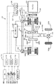
図1は、本発明の一実施例であるハイブリッド自動車20の構成の概略を示す構成図である。実施例のハイブリッド自動車20は、図示するように、エンジン22と、エンジン22の出力軸としてのクランクシャフト26にねじれ要素としてのダンパ28を介して接続された3軸式の動力分配統合機構30と、動力分配統合機構30に接続された発電可能なモータMG1と、動力分配統合機構30に接続された駆動軸としてのリングギヤ軸32aに取り付けられた減速ギヤ35と、この減速ギヤ35に接続されたモータMG2と、車両全体をコントロールするハイブリッド用電子制御ユニット70とを備える。
FIG. 1 is a configuration diagram showing an outline of the configuration of a
エンジン22は、例えばガソリンまたは軽油などの炭化水素系の燃料により動力を出力可能な6気筒の内燃機関として構成されており、図2に示すように、エアクリーナ122により清浄された空気をスロットルバルブ124を介して吸入すると共に気筒毎に設けられた燃料噴射弁126からガソリンを噴射して吸入された空気とガソリンとを混合し、この混合気を吸気バルブ128を介して燃料室に吸入し、点火プラグ130による電気火花によって爆発燃焼させて、そのエネルギにより押し下げられるピストン132の往復運動をクランクシャフト26の回転運動に変換する。エンジン22からの排気は、一酸化炭素(CO)や炭化水素(HC),窒素酸化物(NOx)の有害成分を浄化する浄化装置(三元触媒)134を介して外気へ排出される。
The
エンジン22は、エンジン用電子制御ユニット(以下、エンジンECUという)24により制御されている。エンジンECU24は、CPU24aを中心とするマイクロプロセッサとして構成されており、CPU24aの他に処理プログラムを記憶するROM24bと、データを一時的に記憶するRAM24cと、図示しない入出力ポートおよび通信ポートとを備える。エンジンECU24には、エンジン22の状態を検出する種々のセンサからの信号、クランクシャフト26の回転位置を検出するクランクポジションセンサ140からのクランクポジションやエンジン22の冷却水の温度を検出する水温センサ142からの冷却水温,燃焼室へ吸排気を行なう吸気バルブ128や排気バルブを開閉するカムシャフトの回転位置を検出するカムポジションセンサ144からのカムポジション,スロットルバルブ124のポジションを検出するスロットルバルブポジションセンサ146からのスロットルポジション,吸気管に取り付けられたエアフローメータ148からのエアフローメータ信号AF,同じく吸気管に取り付けられた温度センサ149からの吸気温,空燃比センサ135aからの空燃比AF,酸素センサ135bからの酸素信号などが入力ポートを介して入力されている。また、エンジンECU24からは、エンジン22を駆動するための種々の制御信号、例えば、燃料噴射弁126への駆動信号や、スロットルバルブ124のポジションを調節するスロットルモータ136への駆動信号、イグナイタと一体化されたイグニッションコイル138への制御信号、吸気バルブ128の開閉タイミングの変更可能な可変バルブタイミング機構150への制御信号などが出力ポートを介して出力されている。なお、エンジンECU24は、ハイブリッド用電子制御ユニット70と通信しており、ハイブリッド用電子制御ユニット70からの制御信号によりエンジン22を運転制御すると共に必要に応じてエンジン22の運転状態に関するデータを出力する。
The
動力分配統合機構30は、外歯歯車のサンギヤ31と、このサンギヤ31と同心円上に配置された内歯歯車のリングギヤ32と、サンギヤ31に噛合すると共にリングギヤ32に噛合する複数のピニオンギヤ33と、複数のピニオンギヤ33を自転かつ公転自在に保持するキャリア34とを備え、サンギヤ31とリングギヤ32とキャリア34とを回転要素として差動作用を行なう遊星歯車機構として構成されている。動力分配統合機構30は、キャリア34にはエンジン22のクランクシャフト26が、サンギヤ31にはモータMG1が、リングギヤ32にはリングギヤ軸32aを介して減速ギヤ35がそれぞれ連結されており、モータMG1が発電機として機能するときにはキャリア34から入力されるエンジン22からの動力をサンギヤ31側とリングギヤ32側にそのギヤ比に応じて分配し、モータMG1が電動機として機能するときにはキャリア34から入力されるエンジン22からの動力とサンギヤ31から入力されるモータMG1からの動力を統合してリングギヤ32側に出力する。リングギヤ32に出力された動力は、リングギヤ軸32aからギヤ機構60およびデファレンシャルギヤ62を介して、最終的には車両の駆動輪63a,63bに出力される。
The power distribution and
モータMG1およびモータMG2は、いずれも発電機として駆動することができると共に電動機として駆動できる周知の同期発電電動機として構成されており、インバータ41,42を介してバッテリ50と電力のやりとりを行なう。インバータ41,42とバッテリ50とを接続する電力ライン54は、各インバータ41,42が共用する正極母線および負極母線として構成されており、モータMG1,MG2のいずれかで発電される電力を
他のモータで消費することができるようになっている。したがって、バッテリ50は、モータMG1,MG2のいずれかから生じた電力や不足する電力により充放電されることになる。なお、モータMG1,MG2により電力収支のバランスをとるものとすれば、バッテリ50は充放電されない。モータMG1,MG2は、いずれもモータ用電子制御ユニット(以下、モータECUという)40により駆動制御されている。モータECU40には、モータMG1,MG2を駆動制御するために必要な信号、例えばモータMG1,MG2の回転子の回転位置を検出する回転位置検出センサ43,44からの信号や図示しない電流センサにより検出されるモータMG1,MG2に印加される相電流などが入力されており、モータECU40からは、インバータ41,42へのスイッチング制御信号が出力されている。モータECU40は、ハイブリッド用電子制御ユニット70と通信しており、ハイブリッド用電子制御ユニット70からの制御信号によってモータMG1,MG2を駆動制御すると共に必要に応じてモータMG1,MG2の運転状態に関するデータをハイブリッド用電子制御ユニット70に出力する。
The motor MG1 and the motor MG2 are both configured as well-known synchronous generator motors that can be driven as generators and can be driven as motors, and exchange power with the
バッテリ50は、バッテリ用電子制御ユニット(以下、バッテリECUという)52によって管理されている。バッテリECU52には、バッテリ50を管理するのに必要な信号、例えば、バッテリ50の端子間に設置された図示しない電圧センサからの端子間電圧,バッテリ50の出力端子に接続された電力ライン54に取り付けられた図示しない電流センサからの充放電電流,バッテリ50に取り付けられた温度センサ51からの電池温度Tbなどが入力されており、必要に応じてバッテリ50の状態に関するデータを通信によりハイブリッド用電子制御ユニット70に出力する。なお、バッテリECU52では、バッテリ50を管理するために電流センサにより検出された充放電電流の積算値に基づいて残容量(SOC)も演算している。また、バッテリECU52は、バッテリ50を管理するために電流センサにより検出された充放電電流の積算値に基づいて残容量(SOC)を演算したり、演算した残容量(SOC)と電池温度Tbとに基づいてバッテリ50を充放電してもよい最大許容電力である入出力制限Win,Woutを演算している。
The
ハイブリッド用電子制御ユニット70は、CPU72を中心とするマイクロプロセッサとして構成されており、CPU72の他に処理プログラムを記憶するROM74と、データを一時的に記憶するRAM76と、図示しない入出力ポートおよび通信ポートとを備える。ハイブリッド用電子制御ユニット70には、イグニッションスイッチ80からのイグニッション信号,シフトレバー81の操作位置を検出するシフトポジションセンサ82からのシフトポジションSP,アクセルペダル83の踏み込み量を検出するアクセルペダルポジションセンサ84からのアクセル開度Acc,ブレーキペダル85の踏み込み量を検出するブレーキペダルポジションセンサ86からのブレーキペダルポジションBP,車速センサ88からの車速Vなどが入力ポートを介して入力されている。ハイブリッド用電子制御ユニット70は、前述したように、エンジンECU24やモータECU40,バッテリECU52と通信ポートを介して接続されており、エンジンECU24やモータECU40,バッテリECU52と各種制御信号やデータのやりとりを行なっている。
The hybrid
こうして構成された実施例のハイブリッド自動車20は、運転者によるアクセルペダル83の踏み込み量に対応するアクセル開度Accと車速Vとに基づいて駆動軸としてのリングギヤ軸32aに出力すべき要求トルクを計算し、この要求トルクに対応する要求動力がリングギヤ軸32aに出力されるように、エンジン22とモータMG1とモータMG2とが運転制御される。エンジン22とモータMG1とモータMG2の運転制御としては、要求動力に見合う動力がエンジン22から出力されるようにエンジン22を運転制御すると共にエンジン22から出力される動力のすべてが動力分配統合機構30とモータMG1とモータMG2とによってトルク変換されてリングギヤ軸32aに出力されるようモータMG1およびモータMG2を駆動制御するトルク変換運転モードや要求動力とバッテリ50の充放電に必要な電力との和に見合う動力がエンジン22から出力されるようにエンジン22を運転制御すると共にバッテリ50の充放電を伴ってエンジン22から出力される動力の全部またはその一部が動力分配統合機構30とモータMG1とモータMG2とによるトルク変換を伴って要求動力がリングギヤ軸32aに出力されるようモータMG1およびモータMG2を駆動制御する充放電運転モード、エンジン22の運転を停止してモータMG2からの要求動力に見合う動力をリングギヤ軸32aに出力するよう運転制御するモータ運転モードなどがある。
The
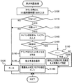
次に、こうして構成された実施例のハイブリッド自動車20の動作、特に、エンジン22の6気筒のうち1気筒だけが連続的に失火している1気筒失火を判定すると共に1気筒失火を判定したときに失火している気筒を特定する際の動作について説明する。図3は、エンジンECU24により実行される失火判定処理の一例を示すフローチャートである。この処理は、所定時間毎に繰り返し実行される。
Next, the operation of the
失火判定処理が実行されると、エンジンECU24のCPU24aは、まず、クランクポジションセンサ140により検出されるクランク角CAや図4に例示するT30演算処理により演算されるクランクシャフト26が30度回転するのに要する時間である30度回転所要時間T30(CA)を入力する処理を実行する(ステップS100)。ここで、30度回転所要時間T30(CA)は、T30演算処理に示すように、クランクポジションセンサ140からのクランク角CAに基づいてクランク角CAが30度回転する毎にそのときの時刻を入力し(ステップS300)、入力した今回の時刻と前回クランク角CAが30度回転したときに入力した時刻との差を計算することにより30度所要時間T30を演算する(ステップS310)、ことにより求めることができる。ここで、30度所要時間T30(CA)は、その逆数をとるとクランクシャフト26が30度回転する毎のエンジン22の回転数(以下、30度回転数N30(CA))となるから、30度回転数N30(CA)の変化の程度、即ち回転変動を時間の単位を用いて表わしたものとなる。
When the misfire determination process is executed, the
続いて、入力した30度回転所要時間T30と閾値Trerとを比較する(ステップS110)。ここで、閾値Trefは、30度回転所要時間T30の基準となるクランク角CAで燃焼行程となる気筒が失火していないときの30度回転所要時間T30より大きく、その気筒が失火しているときの30度回転所要時間T30より小さな値として設定されており、実験などにより求めることができる。30度回転所要時間T30が閾値Tref以下のときには、エンジン22は失火していないと判定し、1気筒失火判定フラグFに値0を設定して(ステップS120)、失火判定処理を終了する。
Subsequently, the input required 30-degree rotation time T30 is compared with the threshold value Trer (step S110). Here, the threshold value Tref is greater than the required 30-degree rotation time T30 when the cylinder that is in the combustion stroke is not misfiring at the crank angle CA that is the reference of the required 30-degree rotation time T30, and the cylinder is misfired. Is set as a value smaller than the required 30-degree rotation time T30, and can be obtained by experiments or the like. When the time required for 30-degree rotation T30 is equal to or less than the threshold value Tref, it is determined that the
30度回転所要時間T30が閾値Trefよりも大きいときには、エンジン22のいずれかの気筒に失火が生じていると判断し、その失火が6気筒のうち1気筒だけが連続的に失火、即ち720度毎のクランク角CAに対応する30度回転所要時間T30が閾値Trefよりも大きい1気筒失火か否かを判定する(ステップS130)。1気筒失火でないと判定されたときには1気筒失火判定フラグFに値0を設定して(ステップS120)、失火判定処理を終了する。
When the time required for 30-degree rotation T30 is greater than the threshold value Tref, it is determined that any cylinder of the
一方、1気筒失火と判定されると、次に、エンジン22の回転数NeとトルクTeとを入力し(ステップS140)、入力した回転数NeとトルクTeとに基づいてエンジン22の運転ポイントがダンパ28を含む後段(動力分配統合機構30など)の共振領域にあるか否かを判定する(ステップS150)。ここで、実施例では、エンジン22の回転数Neについては、クランクポジションセンサ140からのクランク角CAに基づいて演算により求められたものを入力するものとし、トルクTeについては、モータMG1のトルクから計算されたものを入力するものとした。エンジン22の運転ポイントがダンパ28を含む後段の共振領域にあるか否かについては、予め実験などにより共振領域となるエンジン22の回転数NeとトルクTeとを求めて共振運転範囲としてROM24bに記憶しておき、入力したエンジン22の回転数NeとトルクTeが記憶した共振運転範囲に属するか否かにより判定するものとした。なお、共振運転範囲は、エンジン22の特性やダンパ28より後段(動力分配統合機構30)などの特性によって実験により求めることができる。
On the other hand, if it is determined that one cylinder is misfiring, next, the engine speed Ne and torque Te of the
エンジン22の運転ポイントが共振領域にないと判定されると、クランク角CAにより失火気筒を特定し(ステップS160)、特定した失火気筒をRAM24cの所定領域に保存すると共に(ステップS170)、1気筒失火判定フラグFに値1を設定して(ステップS180)、失火判定処理を終了する。一方、エンジン22の運転ポイントが共振領域にあると判定されると、1気筒失火判定フラグFが値1か否かを判定し(ステップS190)、1気筒失火判定フラグFが値1のときには、1気筒失火が継続しており失火気筒はエンジン22の運転ポイントが共振領域にないときにクランク角CAにより特定した気筒とみなすことができると判断し、RAM24cに保存している気筒と同一の気筒を失火気筒として特定して(ステップS200)、失火判定処理を終了し、1気筒失火判定フラグFが値0のときには失火している気筒を特定することができないと判断して失火気筒の特定を行なうことなく失火判定処理を終了する。
If it is determined that the operation point of the
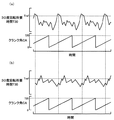
図5に、エンジン22に1気筒失火が生じているときの30度回転所要時間T30とクランク角CAの時間変化の一例を示す。なお、図5(a)は、エンジン22の運転ポイントが共振領域にないときに1気筒失火が生じているときの30度回転所要時間T30とクランク角CAの時間変化を示し、エンジン22の運転ポイントが共振領域に属するときに1気筒失火が生じているときの30度回転所要時間T30とクランク角CAの時間変化を示す。エンジン22の運転ポイントが共振領域にないときには、図5(a)に示すように、クランク角CAが720度に1回の割合で30度回転所要時間T30が閾値Trefを超えており、これにより失火していると判定して対応するクランク角CAに基づいて失火している気筒を特定することができる。一方、エンジン22の運転ポイントが共振領域にあるときには、図5(b)に示すように、ダンパ28を含む後段の共振の影響により、失火している気筒に対応するクランク角CAに対する30度回転所要時間T30が小さな値として現われて閾値Tref以下となると共に失火していない気筒に対応するクランク角CAに対する30度回転所要時間T30が大きな値として現われて閾値Trefを超える場合が生じ、この場合、上述した手法ではいずれの気筒が失火しているのかを特定することができない。実施例では、エンジン22の運転ポイントが共振領域に属しない状態でエンジン22に1気筒失火が生じたときに特定した失火気筒を保存しておき、1気筒失火が継続している状態でエンジン22の運転ポイントが共振領域に属することになったときは保存した気筒と同じ気筒が失火しているとみなすことにより、失火気筒を特定している。
FIG. 5 shows an example of the time change of the 30 ° rotation required time T30 and the crank angle CA when one cylinder misfire occurs in the
以上説明した実施例のハイブリッド自動車20によれば、1気筒失火が判定されたときにエンジン22の運転ポイントがダンパ28を含む後段の共振領域に属しないときには1気筒失火が判定されたときのクランク角CAにより失火気筒を特定してRAM24aに保存し、次回以降に継続して1気筒失火が判定されたときにエンジン22の運転ポイントが共振領域に属するときにはRAM24cに保存した気筒を失火気筒として特定するから、エンジン22の運転ポイントがダンパ28を含む後段の共振領域に属する状態であっても失火していない気筒が失火気筒として誤って特定されるのを抑制することができる。
According to the
実施例のハイブリッド自動車20では、クランクシャフト26が30度回転するのに要する時間としての30度所要時間T30をベースとしてエンジン22の失火を判定するものとしたが、クランクシャフト26が5度回転するのに要する時間として5度所要時間T5や10度回転するのに要する時間として10度所要時間T10など種々の所要時間を用いてエンジン22の失火を判定するものとしてもかまわない。また、5度毎のクランクシャフト26の回転数である5度回転数N5や10度毎のクランクシャフト26の回転数である10度回転数N10など種々の回転数を用いてエンジン22の失火を判定するものとしても構わない。
In the
実施例のハイブリッド自動車20では、6気筒のエンジン22の失火を判定するものとして説明したが、4気筒のエンジンの失火を判定するものとしてもよく、8気筒のエンジンの失火を判定するものとしてもよく、複数気筒であれば如何なるエンジンの失火を判定するものとしてもよい。
In the
実施例のハイブリッド自動車20では、1気筒失火が判定されたときにエンジン22の運転ポイントが共振領域にあるとき、エンジン22の運転ポイントが共振領域にないときに1気筒失火が判定されたときにクランク角CAにより特定してRAM24cに保存した失火気筒と同じ気筒を失火気筒として特定するものとしたが、エンジン22の運転ポイントが共振領域にあるときであってもクランク角CAにより失火気筒を特定すると共に特定した失火気筒とエンジン22の運転ポイントが共振領域にないときにクランク角CAにより特定した失火気筒とが一致するか否かを確認するものとしてもよい。
In the
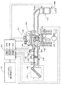
実施例のハイブリッド自動車20では、エンジン22のクランクシャフト26にねじれ要素としてのダンパ28を介して接続されると共にモータMG1の回転軸や駆動軸としてのリングギヤ軸32aに接続される動力分配統合機構30とリングギヤ軸32aに減速ギヤ35を介して接続されるモータMG2とを備える装置におけるエンジン22の失火判定装置としたが、エンジンのクランクシャフトがねじれ要素としてのダンパを介して後段に接続されているものであればよいから、図6の変形例のハイブリッド自動車120に例示するように、モータMG2の動力をリングギヤ軸32aが接続された車軸(駆動輪63a,63bが接続された車軸)とは異なる車軸(図6における車輪64a,64bに接続された車軸)に接続するものとしてもよいし、図7の変形例のハイブリッド自動車220に例示するように、エンジン22のクランクシャフト26にダンパ28を介して接続されたインナーロータ232と駆動輪63a,63bに動力を出力する車軸側に接続されたアウターロータ234とを有し、エンジン22の動力の一部を車軸側に伝達すると共に残余の動力を電力に変換する対ロータ電動機230を備えるもののエンジン22の失火を判定するものとしてもよい。この場合、モータMG2は減速ギヤ35や変速機を介して車軸側に接続されていてもよいし、減速ギヤ35や変速機を介さずに車軸側に接続されていてもよい。
In the
ここで、実施例の主要な要素と課題を解決するための手段の欄に記載した発明の主要な要素との対応関係について説明する。実施例では、エンジン22が「内燃機関」に相当し、クランクポジションセンサ140が「回転位置検出手段」に相当し、クランクポジションセンサ140からのクランク角CAに基づいてクランク角CAが30度回転する毎にそのときの時刻と1つ前の時刻との差を計算することにより30度所要時間T30を演算するT30演算処理を実行するエンジンECU24が「回転変動演算手段」に相当し、720度毎にクランク角CAに対応する30度回転所要時間T30が閾値Trefより大きいか否かを判定する失火判定処理のステップS110,S130の処理を実行するエンジンECU24が「1気筒失火判定手段」に相当し、RAM24cが「記憶手段」に相当し、1気筒失火が判定されたときにエンジン22の運転ポイントがダンパ28を含む後段の共振領域に属しないときには1気筒失火が判定されたときのクランク角CAにより失火気筒として特定してRAM24aに保存すると共に1気筒失火判定フラグFを値1に設定し、1気筒失火が判定されたときにエンジン22の運転ポイントが共振領域に属し且つ1気筒失火判定フラグFが値1であるときにはRAM24cに保存した気筒を失火気筒として特定する失火判定処理のステップS140〜S200の処理を実行するエンジンECU24が「失火気筒特定手段」に相当する。また、モータMG1が「発電機」に相当し、動力分配統合機構30が「3軸式動力入出力手段」に相当し、モータMG2が「電動機」に相当する。
Here, the correspondence between the main elements of the embodiment and the main elements of the invention described in the column of means for solving the problems will be described. In the embodiment, the
ここで、「内燃機関」としては、ガソリンまたは軽油などの炭化水素系の燃料により動力を出力する内燃機関に限定されるものではなく、水素エンジンなど、ダンパなどのねじれ要素を介して後段の後段軸に接続された複数気筒を有するものであれば如何なるタイプの内燃機関であっても構わない。「回転位置検出手段」としては、クランクポジションセンサ140に限定されるものではなく、内燃機関の回転位置を検出できるものであれば、カムポジションセンサ144など他の如何なるものとしても構わない。「回転変動演算手段」としては、クランクポジションセンサ140からのクランク角CAに基づいてクランク角CAが30度回転する毎にそのときの時刻と1つ前の時刻との差を計算することにより30度所要時間T30を演算するものに限定されるものではなく、内燃機関の回転位置に基づいて回転変動を演算するものであれば、他の如何なるものとしても構わない。「1気筒失火判定手段」としては、720度毎にクランク角CAに対応する30度回転所要時間T30が閾値Trefより大きいか否かを判定するものに限定されるものではなく、内燃機関の回転変動に基づいて内燃機関の失火を判定するものであれば、他の如何なるものとしても構わない。「記憶手段」としては、RAM24cに限定されるものではなく、フラッシュメモリなどデータを保存できるものであれば如何なるものであっても構わない。「失火気筒特定手段」としては、1気筒失火が判定されたときにエンジン22の運転ポイントがダンパ28を含む後段の共振領域に属しないときには1気筒失火が判定されたときのクランク角CAにより失火気筒を特定してRAM24aに保存すると共に1気筒失火判定フラグFを値1に設定し、1気筒失火が判定されたときにエンジン22の運転ポイントが共振領域に属し且つ1気筒失火判定フラグFが値1であるときにはRAM24cに保存した気筒を失火気筒として特定するものに限定されるものではなく、内燃機関がねじれ要素のねじれに基づく共振が発生する共振発生領域内の運転ポイントで運転されていないときに1気筒失火判定手段により1気筒失火と判定されたときには1気筒失火と判定した際に用いた出力軸の回転位置に対応する気筒を失火気筒として特定して記憶手段に保存し、内燃機関が共振発生領域内の運転ポイントで運転されているときに1気筒失火判定手段により1気筒失火と判定されたときには保存した気筒と同一の気筒を失火気筒として特定するものであれば如何なるものとしても構わない。「発電機」としては、同期発電電動機として構成されたモータMG1に限定されるものではなく、誘導電動機など、動力を入出力可能なものであれば如何なるタイプの発電機としても構わない。「3軸式動力入出力手段」としては、上述の動力分配統合機構30に限定されるものではなく、ダブルピニオン式の遊星歯車機構を用いるものや複数の遊星歯車機構を組み合わせて4以上の軸に接続されるものやデファレンシャルギヤのように遊星歯車とは異なる差動作用を有するものなど、3軸のうちいずれか2軸に入出力される動力に基づいて残余の1軸に動力を入出力するものであれば如何なるものであっても構わない。「電動機」としては、同期発電電動機として構成されたモータMG2に限定されるものではなく、誘導電動機など、駆動軸に動力を入出力可能なものであれば如何なるタイプの電動機であっても構わない。なお、実施例の主要な要素と課題を解決するための手段の欄に記載した発明の主要な要素との対応関係は、実施例が課題を解決するための手段の欄に記載した発明を実施するための最良の形態を具体的に説明するための一例であることから、課題を解決するための手段の欄に記載した発明の要素を限定するものではない。即ち、課題を解決するための手段の欄に記載した発明についての解釈はその欄の記載に基づいて行なわれるべきものであり、実施例は課題を解決するための手段の欄に記載した発明の具体的な一例に過ぎないものである。
Here, the “internal combustion engine” is not limited to an internal combustion engine that outputs power using a hydrocarbon-based fuel such as gasoline or light oil, but a hydrogen engine or the like and a subsequent stage through a torsion element such as a damper. Any type of internal combustion engine may be used as long as it has a plurality of cylinders connected to the shaft. The “rotational position detecting means” is not limited to the crank position sensor 140, and any other device such as a
実施例では、ハイブリッド自動車20に搭載された内燃機関の失火判定装置として説明したが、走行用の電動機や発電機などを備えない自動車に搭載された内燃機関の失火判定装置に適用するものとしてもよい。また、自動車以外の車両や船舶,航空機などの移動体に搭載される内燃機関の失火判定装置に適用してもよいし、移動しない設備に組み込まれた内燃機関の失火判定装置に適用するものとしても構わない。また、内燃機関の失火判定装置やこれを搭載する車両の形態ではなく、内燃機関の失火判定方法の形態としてもよい。
Although the embodiment has been described as the misfire determination device for an internal combustion engine mounted on the
以上、本発明を実施するための最良の形態について実施例を用いて説明したが、本発明はこうした実施例に何等限定されるものではなく、本発明の要旨を逸脱しない範囲内において、種々なる形態で実施し得ることは勿論である。 The best mode for carrying out the present invention has been described with reference to the embodiments. However, the present invention is not limited to these embodiments, and various modifications can be made without departing from the gist of the present invention. Of course, it can be implemented in the form.
本発明は、自動車産業などに利用可能である。 The present invention is applicable to the automobile industry and the like.
20,120,220 ハイブリッド自動車、22 エンジン、24 エンジン用電子
制御ユニット(エンジンECU)、24a CPU、24b ROM、24c RAM、26 クランクシャフト、28 ダンパ、30 動力分配統合機構、31 サンギヤ、32 リングギヤ、32a リングギヤ軸、33 ピニオンギヤ、34 キャリア、35 減速ギヤ、40 モータ用電子制御ユニット(モータECU)、41,42 インバータ、43,44 回転位置検出センサ、50 バッテリ、51 温度センサ、52 バッテリ用電子制御ユニット(バッテリECU)、54 電力ライン、60 ギヤ機構、62 デファレンシャルギヤ、63a,63b 駆動輪、64a,64b 車輪、70 ハイブリッド用電子制御ユニット、72 CPU、74 ROM、76 RAM、80 イグニッションスイッチ、81 シフトレバー、82 シフトポジションセンサ、83 アクセルペダル、84 アクセルペダルポジションセンサ、85 ブレーキペダル、86 ブレーキペダルポジションセンサ、88 車速センサ、122 エアクリーナ、124 スロットルバルブ、126 燃料噴射弁、128 吸気バルブ、130 点火プラグ、132
ピストン、134 浄化装置、135a 空燃比センサ、135b 酸素センサ、136,スロットルモータ、138 イグニッションコイル、140 クランクポジションセンサ、142 水温センサ、144 カムポジションセンサ、146 スロットルバルブポジションセンサ、148 エアフローメータ、149 温度センサ、150 可変バルブタイミング機構、230 対ロータ電動機、232 インナーロータ、234 アウターロータ、MG1,MG2 モータ。
20, 120, 220 Hybrid vehicle, 22 engine, 24 engine electronic control unit (engine ECU), 24a CPU, 24b ROM, 24c RAM, 26 crankshaft, 28 damper, 30 power distribution integration mechanism, 31 sun gear, 32 ring gear, 32a ring gear shaft, 33 pinion gear, 34 carrier, 35 reduction gear, 40 motor electronic control unit (motor ECU), 41, 42 inverter, 43, 44 rotational position detection sensor, 50 battery, 51 temperature sensor, 52 battery electronic control Unit (battery ECU), 54 power line, 60 gear mechanism, 62 differential gear, 63a, 63b driving wheel, 64a, 64b wheel, 70 hybrid electronic control unit, 72 CPU, 74 ROM, 76 RAM, 0 Ignition switch, 81 Shift lever, 82 Shift position sensor, 83 Accelerator pedal, 84 Accelerator pedal position sensor, 85 Brake pedal, 86 Brake pedal position sensor, 88 Vehicle speed sensor, 122 Air cleaner, 124 Throttle valve, 126 Fuel injection valve, 128 Intake valve, 130 Spark plug, 132
Piston, 134 Purification device, 135a Air-fuel ratio sensor, 135b Oxygen sensor, 136, Throttle motor, 138 Ignition coil, 140 Crank position sensor, 142 Water temperature sensor, 144 Cam position sensor, 146 Throttle valve position sensor, 148 Air flow meter, 149 Temperature Sensor, 150 variable valve timing mechanism, 230 rotor motor, 232 inner rotor, 234 outer rotor, MG1, MG2 motor.
Claims (4)
前記内燃機関の出力軸の回転位置を検出する回転位置検出手段と、
前記検出された出力軸の回転位置に基づいて前記内燃機関の回転変動を演算する回転変動演算手段と、
前記演算された回転変動に基づいて前記内燃機関の複数気筒のうち1気筒が連続的に失火する1気筒失火を判定する1気筒失火判定手段と、
データを記憶する記憶手段と、
前記内燃機関が前記ねじれ要素のねじれに基づく共振が発生する共振発生領域内の運転ポイントで運転されていないときに前記1気筒失火判定手段により1気筒失火と判定されたときには前記1気筒失火と判定した際に用いた前記出力軸の回転位置に対応する気筒を失火気筒として特定して前記記憶手段に保存し、前記内燃機関が前記共振発生領域内の運転ポイントで運転されているときに前記1気筒失火判定手段により1気筒失火と判定されたときには前記保存した気筒と同一の気筒を前記失火気筒として特定する失火気筒特定手段と、
を備える内燃機関の失火判定装置。 A misfire determination device for an internal combustion engine that determines misfire of a multi-cylinder internal combustion engine in which an output shaft is connected to a rear shaft of a rear stage through a torsion element,
Rotational position detecting means for detecting the rotational position of the output shaft of the internal combustion engine;
Rotation fluctuation calculating means for calculating the rotation fluctuation of the internal combustion engine based on the detected rotation position of the output shaft;
One-cylinder misfire determination means for determining one-cylinder misfire in which one cylinder among the plurality of cylinders of the internal combustion engine continuously misfires based on the calculated rotation fluctuation;
Storage means for storing data;
When the internal combustion engine is not operated at an operating point in a resonance generating region where resonance based on torsion of the torsion element is generated, when the one cylinder misfire determination means determines that one cylinder misfire has occurred, it is determined that the one cylinder misfire has occurred. The cylinder corresponding to the rotational position of the output shaft used at the time is specified as a misfiring cylinder and stored in the storage means, and when the internal combustion engine is operated at an operating point in the resonance generating region, Misfire cylinder specifying means for specifying the same cylinder as the stored cylinder as the misfire cylinder when the cylinder misfire determination means determines that one cylinder is misfired;
A misfire determination apparatus for an internal combustion engine.
前記内燃機関の失火を判定する請求項1記載の内燃機関の失火判定装置と、
を備える車両。 A multi-cylinder internal combustion engine whose output shaft is connected to the rear shaft of the rear stage via a torsion element;
The misfire determination device for an internal combustion engine according to claim 1, wherein the misfire determination of the internal combustion engine is determined.
A vehicle comprising:
動力を入出力可能な発電機と、
前記後段軸と前記発電機の回転軸と車軸側の回転軸の3軸に接続され、該3軸のうちいずれか2軸に入出力される動力に基づいて残余の1軸に動力を入出力する3軸式動力入出力手段と、
前記車軸側の回転軸に動力を入出力可能な電動機と、
を備える車両。 The vehicle according to claim 2,
A generator capable of inputting and outputting power;
Connected to three shafts of the rear shaft, the generator rotating shaft and the axle shaft rotating shaft, and power is input / output to the remaining one shaft based on power input / output to any two of the three shafts. Three-axis power input / output means for
An electric motor capable of inputting and outputting power to the rotating shaft on the axle side;
A vehicle comprising:
(a)前記出力軸の回転位置に基づいて前記内燃機関の回転変動を演算し、
(b)前記演算された回転変動に基づいて前記内燃機関の複数気筒のうち1気筒が連続的に失火する1気筒失火を判定し、
(c)前記内燃機関が前記ねじれ要素のねじれに基づく共振が発生する共振発生領域内の運転ポイントで運転されていないときに前記ステップ(b)により1気筒失火と判定されたときには前記1気筒失火と判定した際に用いた前記出力軸の回転位置に対応する気筒を失火気筒として特定して保存し、前記内燃機関が前記共振発生領域内の運転ポイントで運転されているときに前記ステップ(b)により1気筒失火と判定されたときには前記保存した気筒と同一の気筒を前記失火気筒として特定する
内燃機関の失火判定方法。 A misfire determination method for an internal combustion engine for determining misfire of a multi-cylinder internal combustion engine in which an output shaft is connected to a rear stage shaft through a torsion element,
(A) calculating the rotational fluctuation of the internal combustion engine based on the rotational position of the output shaft;
(B) determining one cylinder misfire in which one cylinder among the plurality of cylinders of the internal combustion engine continuously misfires based on the calculated rotation fluctuation;
(C) When the internal combustion engine is not operated at an operating point in a resonance generating region where resonance based on torsion of the torsion element is generated, and when it is determined that one cylinder misfire occurs in the step (b), the one cylinder misfire The cylinder corresponding to the rotational position of the output shaft used at the time of determination is specified and stored as a misfire cylinder, and the step (b) is performed when the internal combustion engine is operated at an operating point in the resonance generating region. ), The same cylinder as the stored cylinder is specified as the misfire cylinder when the misfire is determined as one cylinder misfire.
Priority Applications (1)
| Application Number | Priority Date | Filing Date | Title |
|---|---|---|---|
| JP2008132091A JP2009281186A (en) | 2008-05-20 | 2008-05-20 | Device for determining misfire of internal combustion engine, vehicle, and method for determining misfire of internal combustion engine |
Applications Claiming Priority (1)
| Application Number | Priority Date | Filing Date | Title |
|---|---|---|---|
| JP2008132091A JP2009281186A (en) | 2008-05-20 | 2008-05-20 | Device for determining misfire of internal combustion engine, vehicle, and method for determining misfire of internal combustion engine |
Publications (1)
| Publication Number | Publication Date |
|---|---|
| JP2009281186A true JP2009281186A (en) | 2009-12-03 |
Family
ID=41451906
Family Applications (1)
| Application Number | Title | Priority Date | Filing Date |
|---|---|---|---|
| JP2008132091A Pending JP2009281186A (en) | 2008-05-20 | 2008-05-20 | Device for determining misfire of internal combustion engine, vehicle, and method for determining misfire of internal combustion engine |
Country Status (1)
| Country | Link |
|---|---|
| JP (1) | JP2009281186A (en) |
Cited By (1)
| Publication number | Priority date | Publication date | Assignee | Title |
|---|---|---|---|---|
| CN115182813A (en) * | 2022-07-26 | 2022-10-14 | 东风汽车集团股份有限公司 | Engine fire monitoring method of hybrid electric vehicle |
-
2008
- 2008-05-20 JP JP2008132091A patent/JP2009281186A/en active Pending
Cited By (2)
| Publication number | Priority date | Publication date | Assignee | Title |
|---|---|---|---|---|
| CN115182813A (en) * | 2022-07-26 | 2022-10-14 | 东风汽车集团股份有限公司 | Engine fire monitoring method of hybrid electric vehicle |
| CN115182813B (en) * | 2022-07-26 | 2023-10-20 | 东风汽车集团股份有限公司 | Engine misfire monitoring method of hybrid electric vehicle |
Similar Documents
| Publication | Publication Date | Title |
|---|---|---|
| JP4453654B2 (en) | Internal combustion engine misfire determination device, vehicle equipped with the same, and misfire determination method | |
| JP4702169B2 (en) | INTERNAL COMBUSTION ENGINE DEVICE, VEHICLE EQUIPPED WITH THE SAME AND INTERNAL COMBUSTION ENGINE DETERMINATION METHOD | |
| JP4458105B2 (en) | Internal combustion engine apparatus, vehicle equipped with the same, and misfire determination method | |
| JP4007401B1 (en) | Misfire determination device and misfire determination method for internal combustion engine | |
| JP4337829B2 (en) | Misfire determination device, hybrid vehicle, and misfire determination method | |
| JP2008248877A (en) | Misfire determination device and misfire determination method for internal combustion engines, and vehicle | |
| JP2007198304A (en) | Misfire determination device and misfire determination method for internal combustion engine | |
| JP5011896B2 (en) | Internal combustion engine misfire determination device and vehicle | |
| JP2007170248A (en) | Internal combustion engine apparatus, vehicle mounted therewith, and method of determining misfire of internal combustion engine | |
| JP2007303310A (en) | Internal combustion engine device and misfire judgment method for internal combustion engine | |
| JP2009292362A (en) | Misfire determination device for internal combustion engine, hybrid vehicle and misfire determination method for internal combustion engine | |
| JP2009234364A (en) | Hybrid vehicle and control method thereof | |
| JP4816574B2 (en) | Output state detection device for internal combustion engine, vehicle, and output state detection method for internal combustion engine | |
| JP2009298365A (en) | Power output device, vehicle having the same, and method of controlling power output device | |
| JP2012215178A (en) | Misfire determination device for internal combustion engine | |
| JP2008063975A (en) | Misfire determining device and misfire determining method for internal combustion engine, and vehicle | |
| JP4930419B2 (en) | Internal combustion engine misfire determination apparatus, misfire determination method, and vehicle | |
| JP2008095617A (en) | Misfire determination device and misfire determination method for internal combustion engine | |
| JP4910776B2 (en) | INTERNAL COMBUSTION ENGINE DEVICE, VEHICLE EQUIPPED WITH THE SAME AND INTERNAL COMBUSTION ENGINE DETERMINATION METHOD | |
| JP5044479B2 (en) | Internal combustion engine misfire determination device, vehicle, and internal combustion engine misfire determination method | |
| JP2009281186A (en) | Device for determining misfire of internal combustion engine, vehicle, and method for determining misfire of internal combustion engine | |
| JP2010203408A (en) | Internal combustion engine device, automobile and failure diagnostic method of exhaust gas recirculation device | |
| JP2010069949A (en) | Hybrid car and method for controlling the same | |
| JP2007283899A (en) | Internal combustion engine device, its control method, and vehicle | |
| JP2009154714A (en) | Power output device, and control method for vehicle and the power output device |