JP2009281176A - Exhaust emission control device for internal combustion engine - Google Patents
Exhaust emission control device for internal combustion engine Download PDFInfo
- Publication number
- JP2009281176A JP2009281176A JP2008131804A JP2008131804A JP2009281176A JP 2009281176 A JP2009281176 A JP 2009281176A JP 2008131804 A JP2008131804 A JP 2008131804A JP 2008131804 A JP2008131804 A JP 2008131804A JP 2009281176 A JP2009281176 A JP 2009281176A
- Authority
- JP
- Japan
- Prior art keywords
- fuel ratio
- air
- internal combustion
- combustion engine
- amount
- Prior art date
- Legal status (The legal status is an assumption and is not a legal conclusion. Google has not performed a legal analysis and makes no representation as to the accuracy of the status listed.)
- Pending
Links
Images


Abstract
Description
本発明は、内燃機関の自動停止・自動再始動を行うアイドルストップ車両に搭載される内燃機関の排気浄化装置に関する。 The present invention relates to an exhaust emission control device for an internal combustion engine mounted on an idle stop vehicle that automatically stops and restarts the internal combustion engine.
従来の内燃機関の排気浄化装置として、例えば特許文献1に記載のものがある。このものでは、減速運転中に燃料供給を停止した状態から燃料供給を再開する燃料供給再開時に、排気浄化触媒の酸素蓄積(ストレージ)量を中立状態とするように燃料増量を行い、その燃料増量にともなって点火時期をリタードさせるとともに吸入空気量を増量することで、HC(炭化水素)の排出量を増加させることなく、NOx(窒素酸化物)の排出量を抑制している。
燃料供給遮断状態から燃料供給を再開するときに、触媒内にストレージされる酸素量は、触媒容量や貴金属担時量,触媒の劣化状態などによって異なり、触媒内の酸素ストレージ量を適切に中立状態とするためには、触媒の状態に応じて燃料供給再開時における燃料増量つまり目標空燃比のリッチ度合いを変える必要がある。但し、燃焼限界から目標空燃比のリッチ度合いは制限されるために、過度に目標空燃比をリッチ化すると、燃料供給再開時における燃焼安定性を損ねるおそれがある。 When the fuel supply is restarted from the fuel supply cut-off state, the amount of oxygen stored in the catalyst varies depending on the catalyst capacity, the amount of noble metal, the deterioration of the catalyst, etc., and the oxygen storage amount in the catalyst is appropriately neutralized. In order to achieve this, it is necessary to change the fuel increase amount at the time of resumption of fuel supply, that is, the rich degree of the target air-fuel ratio, according to the state of the catalyst. However, since the degree of richness of the target air-fuel ratio is limited from the combustion limit, if the target air-fuel ratio is excessively enriched, there is a possibility that the combustion stability at the time of resumption of fuel supply may be impaired.
特に、内燃機関の自動停止及び自動再始動を行うアイドルストップ車両の場合、自動再始動における燃料供給の再開時には、内燃機関が停止、つまりクランクシャフトの回転が停止した状態となっているために、上述した特許文献1に記載のような一般的な非アイドルストップ車両のように、減速中に燃料カットを行い、かつ、この減速中つまり内燃機関のクランクシャフトの回転中に燃料供給を再開するものに比して、機関自動再始動時の燃焼安定性つまり始動性の確保が難しく、その燃焼限界から空燃比のリッチ化が大きく制限される。 In particular, in the case of an idle stop vehicle that performs automatic stop and automatic restart of the internal combustion engine, when the fuel supply is restarted in the automatic restart, the internal combustion engine is stopped, that is, the rotation of the crankshaft is stopped. As in the general non-idle stop vehicle described in Patent Document 1 described above, the fuel is cut during deceleration, and the fuel supply is resumed during deceleration, that is, during rotation of the crankshaft of the internal combustion engine. In comparison with this, it is difficult to ensure the combustion stability, that is, the startability at the time of automatic engine restart, and the enrichment of the air-fuel ratio is greatly limited due to the combustion limit.
本発明は、このような課題に鑑みてなされたものであり、アイドルストップ車両における自動再始動に伴う燃料供給再開時に、機関始動性を損ねることなく触媒の酸素ストレージ量を速やかに中立状態へと復帰させることを主たる目的としている。 The present invention has been made in view of such problems, and at the time of resumption of fuel supply accompanying automatic restart in an idle stop vehicle, the oxygen storage amount of the catalyst is quickly brought to a neutral state without impairing engine startability. The main purpose is to restore.
内燃機関の自動停止・自動再始動を行うアイドルストップ車両の内燃機関の排気浄化装置において、内燃機関の排気通路に、酸素ストレージ機能を有する排気浄化触媒を設ける。機関運転状態に応じて目標空燃比と目標吸入空気量を設定し、これら目標空燃比と目標吸入空気量に基づいて燃料噴射量と吸入空気量を制御する。そして、上記自動再始動に伴う燃料供給再開時には、上記目標空燃比をリッチ側に設定しつつ、上記排気浄化触媒内にストレージされた実酸素ストレージ量に基づいて目標吸入空気量を増加側に補正する。 In an exhaust purification device for an internal combustion engine of an idle stop vehicle that automatically stops and restarts the internal combustion engine, an exhaust purification catalyst having an oxygen storage function is provided in an exhaust passage of the internal combustion engine. The target air-fuel ratio and the target intake air amount are set according to the engine operating state, and the fuel injection amount and the intake air amount are controlled based on the target air-fuel ratio and the target intake air amount. When the fuel supply is resumed due to the automatic restart, the target intake air amount is corrected to the increase side based on the actual oxygen storage amount stored in the exhaust purification catalyst while setting the target air-fuel ratio to the rich side. To do.
本発明によれば、アイドルストップ車両における自動再始動に伴う燃料供給再開時に、 目標空燃比をリッチ側に設定しつつ、実酸素ストレージ量に基づいて目標吸入空気量を増加側に補正することで、目標空燃比の過度なリッチ化による機関始動性の低下を招くことなく、触媒の酸素ストレージ量を速やかに中立状態へと復帰させることができる。 According to the present invention, when fuel supply is restarted due to automatic restart in an idle stop vehicle, the target intake air amount is corrected to the increase side based on the actual oxygen storage amount while setting the target air-fuel ratio to the rich side. In addition, the oxygen storage amount of the catalyst can be quickly returned to the neutral state without causing deterioration in engine startability due to excessive enrichment of the target air-fuel ratio.
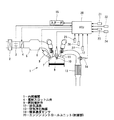
以下、本発明の好ましい実施例を図面に基づいて説明する。図1は、本発明の一実施例に係る内燃機関1の概略構成を示している。内燃機関1に吸入される空気は、エアクリーナ2を通過後、エアフローメータ3で流量を計測されて電制スロットル弁4に導かれる。この電制スロットル弁4により、目標吸入空気量に応じた吸入空気量の制御が行われる。吸入空気は、その後、吸気コレクタ5、吸気マニホールド6を通り、吸気弁7を介して燃焼室8内に導入される。
Hereinafter, preferred embodiments of the present invention will be described with reference to the drawings. FIG. 1 shows a schematic configuration of an internal combustion engine 1 according to an embodiment of the present invention. The air sucked into the internal combustion engine 1 passes through the
燃焼噴射弁9は、燃焼室8内の吸入空気に対して燃料を噴射して混合気を形成し、点火プラグ10は、この混合気を着火燃焼させる。そして、燃焼排気は、排気弁11を介して排気通路12へと排出される。
The combustion injection valve 9 injects fuel to the intake air in the
排気通路12には、排気浄化触媒13が設けられている。この排気浄化触媒13は、例えば、白金(Pt)−ロジウム(Rh)やパラジウム(Pd)−ロジウム系の貴金属(触媒成分)と、セリア(CeO2)やランタン(La)などの添加物(助触媒)とが担持された三元触媒であり、理論空燃比(酸素ストレージ量が理論空燃比相当の中立状態)において、排気中の有害成分であるCO、HC、NOxを高い効率で浄化する。排気浄化触媒13の上流側には、排気中の酸素濃度を検出する酸素濃度センサ14が設けられており、内燃機関1を理論空燃比で運転するときには、燃料噴射制御に際し、この酸素濃度センサ14の出力信号に基づく空燃比フィードバック制御が実行される。
An
上記の電制スロットル弁4による吸入空気量、燃料噴射弁9による燃料噴射量、及び点火プラグ10による点火時期などは、制御部としてのエンジンコントロールユニット(以下「ECU」という)20によって制御される。ECU20には、エアフローメータ3により検出される吸入空気量Qa、酸素濃度センサ14の出力信号のほか、アクセルペダルセンサ21により検出されるアクセル開度APO、クランク角センサ22により検出される機関回転速度Ne、水温センサ23により検出される機関冷却水温度Tw、吸気圧センサ24により検出される吸気圧力Pa,車速センサ25により検出される車速V、ブレーキセンサ26により検出されるブレーキ(図示省略)の作動(ON/OFF)、シフトレバー位置センサ27により検出される自動変速機(図示省略)のシフトレバー位置などが入力される。
The intake air amount by the electric throttle valve 4, the fuel injection amount by the fuel injection valve 9, the ignition timing by the
そして、ECU20は、通常運転時においては、主にアクセル開度APOに基づいて内燃機関1の要求トルクを算出tTeし、この要求トルクtTe、機関回転速度Ne、機関冷却水温度Tw等に基づいて、目標空燃比に相当する目標当量比TFBYAを算出する。この目標当量比TFBYAは空気過剰率λの逆数であり、理論空燃比では1.0、リーン空燃比では1より小さな値、リッチ空燃比では1より大きな値をとる。そして、かかる目標当量比TFBYAを実現するために必要な空気量を得るように電制スロットル弁4を駆動する。また、吸入空気量Qaと機関回転速度Neとから、基本燃料噴射量Tp=K×Qa/Ne(K;定数)を算出し、これに目標当量比TFBYAを乗算することで最終的な燃料噴射量Ti=Tp×TFBYA×COEF(COEF;各種補正係数)を演算する。そして、この最終的な燃料噴射量Tiに相当するパルス幅の燃料噴射パルス信号を出力して燃料噴射弁9を駆動する。なお、点火プラグ10による点火時期は、機関回転速度Ne及び要求トルクtTe等に基づいて制御される。
During normal operation, the
さらに、ECU20は、所定のアイドルストップ条件が成立した場合には、内燃機関1を自動停止させるアイドルストップを実行するとともに、アイドルストップ実行中に所定のアイドルストップ解除条件が成立した場合には、アイドルストップを解除して自動的にスタータ15を駆動して内燃機関1を再始動させる、いわゆるアイドルストップ(自動停止・再始動)制御を行う。
Further, the
図2は、内燃機関の定常走行状態A1,減速状態A2,停止状態A3を経て再始動状態A4に至る機関運転状況における車速,空燃比(A/F),機関回転数及び機関再始動時の吸入空気量の変化の様子を示すタイミングチャートである。 FIG. 2 shows the vehicle speed, the air-fuel ratio (A / F), the engine speed, and the engine restart speed in the engine operation state that reaches the restart state A4 through the steady state A1, the deceleration state A2, the stop state A3 of the internal combustion engine. It is a timing chart which shows the mode of change of the amount of intake air.
定常走行状態A1では、目標空燃比に対応する目標当量比TFBYAを理論空燃比に相当する1.0に設定し、上述した空燃比フィードバック制御が行われる。減速状態A2へ移行すると、燃料供給の停止いわゆる燃料カットを行い、その後、車速の低下に伴って機関回転数も低下し、車両が停止すると機関回転数もゼロとなって機関自動停止状態となる。つまり本実施例のアイドルストップ車両においては、車両減速中に機関回転数がアイドル回転数以下に低下しても燃料供給を再開することなく、機関自動停止いわゆるアイドルストップ状態へ移行することとなる。このように減速状態A2へ移行すると速やかに燃料カットが行われるために、減速状態Aから停止状態A3にかけては、触媒の酸素ストレージ量が不可避的に大きくリーン化されることとなる。 In the steady running state A1, the target equivalent ratio TFBYA corresponding to the target air-fuel ratio is set to 1.0 corresponding to the theoretical air-fuel ratio, and the above-described air-fuel ratio feedback control is performed. When shifting to the deceleration state A2, the fuel supply is stopped, so-called fuel cut is performed, and then the engine speed decreases as the vehicle speed decreases. When the vehicle stops, the engine speed becomes zero and the engine is automatically stopped. . In other words, in the idle stop vehicle of this embodiment, even if the engine speed drops below the idle speed during vehicle deceleration, the fuel supply is not resumed, and the engine automatically stops, so-called idle stop state. As described above, since the fuel cut is performed promptly when shifting to the deceleration state A2, the oxygen storage amount of the catalyst inevitably becomes leaner from the deceleration state A to the stop state A3.
そこで本実施例では、このような減速に伴う燃料カット後の機関自動停止状態A3からの機関自動再始動に伴う燃料供給再開時に、目標空燃比をリッチ側に設定しつつ、実酸素ストレージ量に基づいて目標吸入空気量を増加側に補正している。 Therefore, in this embodiment, when the fuel supply is restarted due to the automatic engine restart from the engine automatic stop state A3 after the fuel cut accompanying the deceleration, the target air-fuel ratio is set to the rich side and the actual oxygen storage amount is set. Based on this, the target intake air amount is corrected to the increase side.
図3は、このような機関自動再始動に伴う燃料供給再開時における目標空燃比(目標当量比TFBYA)及び目標吸入空気量の設定処理の流れを示すフローチャートである。ステップS11では、機関自動再始動要求の有無を判定する。例えば、(1)ブレーキがOFFされたこと、又は(2)ドライバーによる発進操作(アクセル操作等)があったことが再始動要求の条件とされる。再始動要求有りと判定されると、ステップS12以降へ進む。 FIG. 3 is a flowchart showing the flow of processing for setting the target air-fuel ratio (target equivalent ratio TFBYA) and the target intake air amount when fuel supply is restarted due to such automatic engine restart. In step S11, it is determined whether or not there is an engine automatic restart request. For example, (1) the brake is turned off, or (2) the start operation (accelerator operation or the like) by the driver is a condition for the restart request. If it is determined that there is a restart request, the process proceeds to step S12 and subsequent steps.
このステップS12では、排気浄化触媒13にストレージされている実酸素ストレージ量(OSC)を読み込む。この実酸素ストレージ量は図示せぬ他のルーチンによって酸素濃度センサ14の検出信号等に基づいて常時検出・監視されている。ステップS13では、実OSCに基づいて、再始動に伴う燃料供給再開時において、触媒内の酸素ストレージ量を中立状態とするために必要な目標空燃比、つまり目標空燃比のリッチ側への補正分を算出する。
In this step S12, the actual oxygen storage amount (OSC) stored in the
ステップS14では、内燃機関の燃焼限界から要求される機関再始動時における目標空燃比のリッチ限界である限界空燃比λ0を読み込む。この限界空燃比λ0は、基本的には内燃機関の燃焼限界や機関再始動時における空燃比のばらつきなどを考慮して予め設定,記憶される固定値である。但し、触媒温度が高温で、しかも触媒内の雰囲気がリッチの場合には触媒の劣化が進行し易いことから、好ましくは触媒温度に応じて限界空燃比λ0を補正する。具体的には、触媒温度が高くなるほど限界空燃比λ0をリーン側に補正する。触媒温度は、酸素濃度センサ14の検出信号等に基づいて推定することができるが、温度センサを設けて直接的に検出するようにしても良い。
In step S14, the limit air-fuel ratio λ0, which is the rich limit of the target air-fuel ratio at the time of engine restart required from the combustion limit of the internal combustion engine, is read. This limit air-fuel ratio λ0 is basically a fixed value that is preset and stored in consideration of the combustion limit of the internal combustion engine and the variation in air-fuel ratio when the engine is restarted. However, when the catalyst temperature is high and the atmosphere in the catalyst is rich, the deterioration of the catalyst is likely to proceed. Therefore, the limit air-fuel ratio λ0 is preferably corrected according to the catalyst temperature. Specifically, the limit air-fuel ratio λ0 is corrected to the lean side as the catalyst temperature increases. The catalyst temperature can be estimated based on a detection signal of the
ステップS15では、限界空燃比λ0と中立用空燃比λ1とを比較する。中立用空燃比λ1が限界空燃比λ0を超えている場合、ステップS16へ進み、目標空燃比を限界空燃比λ0に設定する。そして、ステップS17において、中立用空燃比λ1と限界空燃比λ0との差分(λ1−λ0)に応じて、目標吸入空気量を増量、つまり増加側へ補正する。図2の矢印Y1に示す破線部分が増量分に相当する。 In step S15, the limit air-fuel ratio λ0 is compared with the neutral air-fuel ratio λ1. When the neutral air-fuel ratio λ1 exceeds the limit air-fuel ratio λ0, the process proceeds to step S16, and the target air-fuel ratio is set to the limit air-fuel ratio λ0. Then, in step S17, the target intake air amount is corrected to be increased, that is, increased in accordance with the difference (λ1-λ0) between the neutral air-fuel ratio λ1 and the limit air-fuel ratio λ0. A broken line portion indicated by an arrow Y1 in FIG. 2 corresponds to the increased amount.
これによって、目標空燃比のリッチ側への補正を燃焼限界に対応する限界空燃比λ0に制限しつつ、吸入空気量の増加によるリッチ化された排気ガスボリュームの増加により、機関再始動時における燃焼安定性つまり始動性を確保しつつ、触媒内を速やかに中立状態へ戻すことができる。ここで、吸入空気量の増加により機関出力が大きくなるものの、車両自動停止状態からの機関再始動は概ね加速状態であるため、搭乗者へ違和感を与えることはあまりなく、機関運転性への跳ね返りは少ない。 As a result, while the correction of the target air-fuel ratio to the rich side is limited to the limit air-fuel ratio λ0 corresponding to the combustion limit, the increase in the exhaust gas volume enriched by the increase in the intake air amount causes the combustion at the time of engine restart While ensuring stability, that is, startability, the inside of the catalyst can be quickly returned to the neutral state. Here, although the engine output increases due to an increase in the intake air amount, the engine restart from the vehicle automatic stop state is almost an acceleration state, so there is not much discomfort to the passengers, and it rebounds to engine operability. There are few.
一方、中立用空燃比λ1が限界空燃比λ0以下の場合、ステップS15からステップS18へ進み、目標空燃比を中立用空燃比λ1に設定する。すなわち、中立用空燃比λ1が限界空燃比λ0以下の場合には、目標吸入空気量を補正することなく、目標空燃比のリッチ側の補正のみで対応している。 On the other hand, when the neutral air-fuel ratio λ1 is equal to or less than the limit air-fuel ratio λ0, the process proceeds from step S15 to step S18, and the target air-fuel ratio is set to the neutral air-fuel ratio λ1. That is, when the neutral air-fuel ratio λ1 is equal to or less than the limit air-fuel ratio λ0, the target intake air amount is not corrected, and only the correction on the rich side of the target air-fuel ratio is supported.
このような本実施例の特徴的な構成及び作用効果について以下に列記する。 Such characteristic configurations and operational effects of this embodiment will be listed below.
(1)内燃機関1の排気通路12に配設され、酸素ストレージ機能を有する排気浄化触媒13と、機関運転状態に応じて目標空燃比(目標当量比TFBYA)と目標吸入空気量を設定し、これら目標空燃比と目標吸入空気量に基づいて燃料噴射量と吸入空気量を制御するECU(制御部)20と、を有し、内燃機関の自動停止・自動再始動を行うアイドルストップを実現可能である。そして、自動再始動に伴う燃料供給再開時(ステップS11)に、目標空燃比をリッチ側に設定しつつ(ステップS16,S18)、排気浄化触媒13内にストレージされた実酸素ストレージ量(ステップS12)に基づいて、目標吸入空気量を増加側に補正している(ステップS17)。
(1) An
燃料カットから機関自動停止までのクランクシャフトを含む主運動系の空転により、機関停止状態での触媒内の酸素ストレージ量はリーン化されており、機関再始動に伴う燃料供給再開時には、排気エミッションの悪化を招くことのないように、触媒内を速やかに中立状態へ復帰させる必要がある。但し、自動再始動における燃料供給再開時には、空燃比を過度にリッチにすると、燃焼安定性つまり機関始動性を確保することができない。本実施例では、目標空燃比をリッチ側に設定しつつ、実酸素ストレージ量に基づいて目標吸入空気量を増加側に補正することにより、目標空燃比の過度なリッチ化による燃焼安定性の低下を招くことなく、触媒の酸素ストレージ量を速やかに中立状態へと復帰させることができる。目標吸入空気量の増加により機関出力は増加するものの、一般的に機関再始動時は加速状態にあるため、運転性への跳ね返りは少ない。 Due to idling of the main motion system including the crankshaft from the fuel cut to the engine automatic stop, the oxygen storage amount in the catalyst when the engine is stopped is made lean, and when the fuel supply is restarted due to the engine restart, the exhaust emission is reduced. It is necessary to promptly return the inside of the catalyst to the neutral state so as not to cause deterioration. However, when the fuel supply is restarted in the automatic restart, if the air-fuel ratio is excessively rich, combustion stability, that is, engine startability cannot be ensured. In this embodiment, while setting the target air-fuel ratio to the rich side, the target intake air amount is corrected to the increase side based on the actual oxygen storage amount, thereby reducing the combustion stability due to excessive enrichment of the target air-fuel ratio. Thus, the oxygen storage amount of the catalyst can be quickly returned to the neutral state. Although the engine output increases due to the increase in the target intake air amount, the engine is generally in an accelerated state when the engine is restarted, so that there is little rebound to drivability.
(2)より具体的には、自動再始動における燃料供給再開時に、実酸素ストレージ量に基づいて、排気浄化触媒内の酸素ストレージ量が理論空燃比相当の中立状態となるのに必要なリッチ側の中立用空燃比λ1を算出するとともに(ステップS13)、この自動再始動時における内燃機関の燃焼限界から定まるリッチ側の限界空燃比λ0を算出し(ステップS14)、これら中立用空燃比λ1と限界空燃比λ0とを比較し(ステップS15)、中立用空燃比λ1が限界空燃比λ0を超える場合に、目標空燃比を限界空燃比λ0に設定するとともに(ステップS16)、中立用空燃比λ1と限界空燃比λ0との差分に応じて目標吸入空気量を増加側へ補正している(ステップS17)。これにより、酸素ストレージ量を中立状態へ復帰させつつ、目標吸入空気量の増加分を精度良く求め、吸入空気量の増量を最小限に抑制することができる。 (2) More specifically, the rich side necessary for the oxygen storage amount in the exhaust purification catalyst to be in a neutral state equivalent to the stoichiometric air-fuel ratio based on the actual oxygen storage amount when the fuel supply is restarted in the automatic restart. The neutral air-fuel ratio λ1 is calculated (step S13), and the rich limit air-fuel ratio λ0 determined from the combustion limit of the internal combustion engine at the time of this automatic restart is calculated (step S14). The limit air-fuel ratio λ0 is compared (step S15). If the neutral air-fuel ratio λ1 exceeds the limit air-fuel ratio λ0, the target air-fuel ratio is set to the limit air-fuel ratio λ0 (step S16), and the neutral air-fuel ratio λ1 is set. The target intake air amount is corrected to the increasing side according to the difference between the air-fuel ratio and the limit air-fuel ratio λ0 (step S17). As a result, the amount of increase in the target intake air amount can be obtained with high accuracy while returning the oxygen storage amount to the neutral state, and the increase in the intake air amount can be minimized.
(3)更に、中立用空燃比λ1が限界空燃比λ0以下の場合には、目標吸入空気量を補正することなく、目標空燃比を中立用空燃比λ1に設定する(ステップS18)。つまり、空燃比のリッチ化のみで対応できる場合には、運転性への跳ね返りを招くことのにあように吸入空気量の増加を行わない。 (3) Further, when the neutral air-fuel ratio λ1 is equal to or less than the limit air-fuel ratio λ0, the target air-fuel ratio is set to the neutral air-fuel ratio λ1 without correcting the target intake air amount (step S18). In other words, if the air / fuel ratio can be dealt with only by enrichment, the intake air amount is not increased as if rebounding to drivability is caused.
(4)排気浄化触媒13の触媒温度に応じて限界空燃比λ0を補正し、より詳しくは触媒温度が高くなるほど触媒が劣化し易い状況となるので、限界空燃比をリーン側へ補正することで、触媒の劣化を良好に防止することができる。
(4) The limit air-fuel ratio λ0 is corrected in accordance with the catalyst temperature of the
以上のように本発明を具体的な実施例に基づいて説明してきたが、本発明は上記実施例に限定されるものではなく、その趣旨を逸脱しない範囲で、種々の変形・変更を含むものである。例えば、上記実施例では動力源を内燃機関のみとするアイドルストップ車両に適用しているが、電動モータと内燃機関とを併用するハイブリッド車両にも同様に適用することができる。また、上記実施例では、減速に伴う燃料カット後の機関自動停止からの機関自動再始動時について説明してきたが、これに限らず、例えばアイドル状態からの燃料カット及び機関自動停止からの機関自動再始動時にも同様に適用できる。 As described above, the present invention has been described based on the specific embodiments. However, the present invention is not limited to the above-described embodiments, and includes various modifications and changes without departing from the spirit of the present invention. . For example, in the above embodiment, the present invention is applied to an idle stop vehicle in which the power source is only an internal combustion engine, but the present invention can be similarly applied to a hybrid vehicle using both an electric motor and an internal combustion engine. In the above-described embodiment, the description has been given of the automatic engine restart from the automatic engine stop after the fuel cut due to the deceleration. However, the present invention is not limited to this. For example, the engine automatic from the idle state and the automatic engine stop from the engine automatic stop. The same applies when restarting.
1…内燃機関
4…電制スロットル弁
9…燃料噴射弁
12…排気通路
13…排気浄化触媒
14…酸素濃度センサ
20…エンジンコントロールユニット(制御部)
DESCRIPTION OF SYMBOLS 1 ... Internal combustion engine 4 ... Electric throttle valve 9 ...
Claims (4)
機関運転状態に応じて目標空燃比と目標吸入空気量を設定し、これら目標空燃比と目標吸入空気量に基づいて燃料噴射量と吸入空気量を制御する制御部と、を有し、内燃機関の自動停止・自動再始動を行うアイドルストップ車両の内燃機関の排気浄化装置において、
上記制御部は、上記自動再始動に伴う燃料供給再開時に、上記目標空燃比をリッチ側に設定しつつ、上記排気浄化触媒内にストレージされた実酸素ストレージ量に基づいて目標吸入空気量を増加側に補正する、
ことを特徴とする内燃機関の排気浄化装置。 An exhaust purification catalyst disposed in an exhaust passage of the internal combustion engine and having an oxygen storage function;
A control unit configured to set a target air-fuel ratio and a target intake air amount in accordance with an engine operating state and control a fuel injection amount and an intake air amount based on the target air-fuel ratio and the target intake air amount, and an internal combustion engine In an exhaust purification device for an internal combustion engine of an idle stop vehicle that performs automatic stop / automatic restart of
The control unit increases the target intake air amount based on the actual oxygen storage amount stored in the exhaust purification catalyst while setting the target air-fuel ratio to the rich side when the fuel supply is resumed due to the automatic restart. Correct to the side,
An exhaust emission control device for an internal combustion engine.
上記自動再始動における燃料供給再開時に、上記実酸素ストレージ量に基づいて、排気浄化触媒内の酸素ストレージ量が理論空燃比相当の中立状態となるのに必要なリッチ側の中立用空燃比を算出し、
この中立用空燃比と、自動再始動時における内燃機関の燃焼限界から定まるリッチ側の限界空燃比と、を比較し、
上記中立用空燃比が限界空燃比を超える場合に、目標空燃比を限界空燃比に設定するとともに、中立用空燃比と限界空燃比との差分に応じて目標吸入空気量を増加側に補正する、
ことを特徴とする請求項1に記載の内燃機関の排気浄化装置。 The control unit
When the fuel supply is restarted in the automatic restart, the neutral air-fuel ratio on the rich side necessary for the oxygen storage amount in the exhaust purification catalyst to be in a neutral state equivalent to the theoretical air-fuel ratio is calculated based on the actual oxygen storage amount And
Compare this neutral air-fuel ratio with the rich limit air-fuel ratio determined from the combustion limit of the internal combustion engine at the time of automatic restart,
When the neutral air-fuel ratio exceeds the limit air-fuel ratio, the target air-fuel ratio is set to the limit air-fuel ratio, and the target intake air amount is corrected to increase according to the difference between the neutral air-fuel ratio and the limit air-fuel ratio. ,
The exhaust emission control device for an internal combustion engine according to claim 1.
Priority Applications (1)
| Application Number | Priority Date | Filing Date | Title |
|---|---|---|---|
| JP2008131804A JP2009281176A (en) | 2008-05-20 | 2008-05-20 | Exhaust emission control device for internal combustion engine |
Applications Claiming Priority (1)
| Application Number | Priority Date | Filing Date | Title |
|---|---|---|---|
| JP2008131804A JP2009281176A (en) | 2008-05-20 | 2008-05-20 | Exhaust emission control device for internal combustion engine |
Publications (1)
| Publication Number | Publication Date |
|---|---|
| JP2009281176A true JP2009281176A (en) | 2009-12-03 |
Family
ID=41451899
Family Applications (1)
| Application Number | Title | Priority Date | Filing Date |
|---|---|---|---|
| JP2008131804A Pending JP2009281176A (en) | 2008-05-20 | 2008-05-20 | Exhaust emission control device for internal combustion engine |
Country Status (1)
| Country | Link |
|---|---|
| JP (1) | JP2009281176A (en) |
Cited By (2)
| Publication number | Priority date | Publication date | Assignee | Title |
|---|---|---|---|---|
| JP2014227937A (en) * | 2013-05-23 | 2014-12-08 | ダイハツ工業株式会社 | Controller of internal combustion engine |
| WO2018093389A1 (en) * | 2016-11-21 | 2018-05-24 | Cummins Inc. | Engine response to load shedding by means of a skip-spark/fuel strategy |
-
2008
- 2008-05-20 JP JP2008131804A patent/JP2009281176A/en active Pending
Cited By (3)
| Publication number | Priority date | Publication date | Assignee | Title |
|---|---|---|---|---|
| JP2014227937A (en) * | 2013-05-23 | 2014-12-08 | ダイハツ工業株式会社 | Controller of internal combustion engine |
| WO2018093389A1 (en) * | 2016-11-21 | 2018-05-24 | Cummins Inc. | Engine response to load shedding by means of a skip-spark/fuel strategy |
| US10961927B2 (en) | 2016-11-21 | 2021-03-30 | Cummins Inc. | Engine response to load shedding by means of a skip-spark/fuel strategy |
Similar Documents
| Publication | Publication Date | Title |
|---|---|---|
| JP5278753B2 (en) | Automatic stop / start control device for internal combustion engine | |
| JP5796635B2 (en) | Fuel cut control device and fuel cut control method for internal combustion engine | |
| JP2007032358A (en) | Control device for internal combustion engine | |
| JP2010019178A (en) | Engine control device | |
| JP6288419B2 (en) | Engine fuel injection control device | |
| JP2010223008A (en) | Automatic start-stop control device for internal combustion engine | |
| JP4747809B2 (en) | Engine exhaust purification system | |
| JP6269427B2 (en) | Control device for internal combustion engine | |
| JP5626145B2 (en) | Engine control device | |
| JP4894521B2 (en) | Air-fuel ratio sensor deterioration diagnosis device | |
| JP4244824B2 (en) | Fuel injection control device for internal combustion engine | |
| JP4737005B2 (en) | Engine control device | |
| JP2006220085A (en) | Controller of internal combustion engine | |
| JP2009281176A (en) | Exhaust emission control device for internal combustion engine | |
| JP5392021B2 (en) | Fuel injection control device for internal combustion engine | |
| JP5074717B2 (en) | Fuel injection control device for internal combustion engine | |
| JP2000130221A (en) | Fuel injection control device of internal combustion engine | |
| JP5427525B2 (en) | Automatic engine stop control device | |
| JPH09177580A (en) | Fuel supply controller of internal combustion engine | |
| JP2012036849A (en) | Air-fuel ratio control method of internal combustion engine | |
| JP5152134B2 (en) | Automatic engine stop control device | |
| JP4269279B2 (en) | Control device for internal combustion engine | |
| JP2008202563A (en) | Air/fuel ratio control device for internal combustion engine | |
| JP2005083205A (en) | Control device for internal combustion engine | |
| JP2000230420A (en) | Exhaust emission control device for internal combustion engine |