JP2009281149A - Engine control device and working machine equipped with the same - Google Patents
Engine control device and working machine equipped with the same Download PDFInfo
- Publication number
- JP2009281149A JP2009281149A JP2008130842A JP2008130842A JP2009281149A JP 2009281149 A JP2009281149 A JP 2009281149A JP 2008130842 A JP2008130842 A JP 2008130842A JP 2008130842 A JP2008130842 A JP 2008130842A JP 2009281149 A JP2009281149 A JP 2009281149A
- Authority
- JP
- Japan
- Prior art keywords
- engine
- rotation speed
- speed
- hydraulic pump
- flow rate
- Prior art date
- Legal status (The legal status is an assumption and is not a legal conclusion. Google has not performed a legal analysis and makes no representation as to the accuracy of the status listed.)
- Pending
Links
Images


Landscapes
- Operation Control Of Excavators (AREA)
- Control Of Vehicle Engines Or Engines For Specific Uses (AREA)
Abstract
Description
本発明は、油圧ポンプを駆動するためのエンジンを制御するエンジン制御装置に関するものである。 The present invention relates to an engine control device that controls an engine for driving a hydraulic pump.
従来から、エンジンによって駆動される可変容量型の油圧ポンプと、この油圧ポンプから供給される作動油によって駆動するアクチュエータとを備えた作業機械が知られている。 2. Description of the Related Art Conventionally, a working machine including a variable displacement hydraulic pump driven by an engine and an actuator driven by hydraulic oil supplied from the hydraulic pump is known.
この種の作業機械では、アクチュエータに要求される動力に応じてエンジンの回転数を制御するエンジン制御装置を備えたもの(例えば、特許文献1)が知られている。 In this type of work machine, one having an engine control device that controls the number of revolutions of the engine according to the power required for the actuator is known (for example, Patent Document 1).
特許文献1のエンジン制御装置は、操作レバーの操作量に応じて算出された油圧ポンプの目標流量を当該油圧ポンプの最大傾転で吐出させるためのエンジン回転数(以下、第一回転数と称す)と、前記目標流量を吐出させるために要する油圧ポンプの必要馬力を得ることができるとともに燃料消費率が最も低くなるエンジン回転数(以下、第二回転数と称す)とを算出し、これら第一及び第二回転数のうち回転数の大きな方を選択するようになっている。
ところで、油圧ポンプの吐出量を増大させるためには、油圧ポンプの傾転を大きくするか、又はエンジンの回転数を大きくすることが考えられるが、エンジン回転数を大きくするためには、傾転を大きくする場合よりも長い時間を要するため、吐出量の増大について応答性を良好にするためには、油圧ポンプの傾転を調整することが望まれる。 By the way, in order to increase the discharge amount of the hydraulic pump, it is conceivable to increase the tilt of the hydraulic pump or increase the engine speed, but in order to increase the engine speed, the tilt is increased. Since it takes a longer time than when increasing the flow rate, it is desirable to adjust the tilt of the hydraulic pump in order to improve the responsiveness with respect to the increase in the discharge amount.
そして、前記特許文献1のエンジン制御装置において、第一回転数が選択された場合、エンジン回転数を小さくすることにより油圧ポンプの傾転を最大にして燃費の改善を図ることができるものの、傾転をさらに大きくすることができないため流量を確保するためにはエンジン回転数を上げざるを得ず、目標流量を得るための応答性が悪化するという問題があった。
In the engine control device of
一方、第二回転数が選択された場合においても、このように選択されたエンジン回転数に対応して設定される油圧ポンプの傾転が最大傾転に近いものであるときには、その後、目標流量が急激に増大した場合に前記と同様に目標流量を得るための応答性が悪化するという問題があった。 On the other hand, even when the second rotational speed is selected, when the tilt of the hydraulic pump set corresponding to the engine speed selected in this way is close to the maximum tilt, the target flow rate is thereafter increased. There has been a problem that the responsiveness for obtaining the target flow rate is deteriorated in the same manner as described above when the value increases rapidly.
本発明は、上記課題に鑑みてなされたものであり、目標流量が急激に増大した場合でも応答性の悪化を抑制することができるエンジン制御装置及びこれを備えた作業機械を提供することを目的としている。 The present invention has been made in view of the above problems, and an object of the present invention is to provide an engine control device that can suppress deterioration of responsiveness even when the target flow rate is rapidly increased, and a work machine including the same. It is said.
上記課題を解決するために、本発明は、エンジンと、このエンジンによって駆動される可変容量型の油圧ポンプと、この油圧ポンプから供給される作動油により駆動されるアクチュエータと、このアクチュエータに要求される作動油流量を吐出するための前記油圧ポンプの傾転を前記エンジン回転数に応じて調整する調整手段とを備えた作業機械に設けられ、前記アクチュエータに要求される作動油流量に基づいて前記エンジンの回転数を制御するエンジン制御装置であって、前記アクチュエータに要求される作動油流量に基づいてエンジンの目標回転数を設定する回転数設定手段と、この回転数設定手段により設定された目標回転数に基づいて前記エンジンの回転数を調整する回転数調整手段と、前記アクチュエータに要求される作動油流量が急激に増加する可能性のある急負荷作業の期間中にあるか否かを判定する作業状態判定手段とを備え、前記回転数設定手段は、前記作業状態判定手段により急負荷作業期間中にはないと判定された場合には通常時目標回転数を設定する一方、前記作業状態判定手段により急負荷作業期間中にあると判定された場合には前記通常時目標回転数以上の急負荷時目標回転数を設定することを特徴とするエンジン制御装置を提供する。 In order to solve the above problems, the present invention is required for an engine, a variable displacement hydraulic pump driven by the engine, an actuator driven by hydraulic fluid supplied from the hydraulic pump, and the actuator. And an adjusting means for adjusting the tilt of the hydraulic pump for discharging the hydraulic oil flow rate according to the engine speed, and based on the hydraulic oil flow rate required for the actuator An engine control device for controlling the engine speed, the engine speed setting means for setting a target engine speed based on a hydraulic oil flow rate required for the actuator, and a target set by the speed setting means Rotational speed adjusting means for adjusting the rotational speed of the engine based on the rotational speed, and hydraulic fluid flow required for the actuator Working state determining means for determining whether or not the engine is in a period of sudden load work in which there is a possibility of sudden increase, and the rotation speed setting means is provided during the sudden load work period by the working state determination means. When it is determined that there is not, the normal target rotational speed is set, while when it is determined by the working state determination means that it is during the sudden load work period, the sudden rotational speed is higher than the normal target rotational speed An engine control device characterized by setting a target rotational speed is provided.
本発明によれば、アクチュエータに要求される作動油流量が急激に増加する可能性のある急負荷作業期間にあると判定された場合に設定される急負荷時目標回転数が、急負荷作業期間中にないと判定された通常時回転数以上の回転数に設定されるため、その分、通常作業時よりも油圧ポンプの傾転を小さく維持することができる。 According to the present invention, the target rotational speed at the time of a sudden load that is set when it is determined that the hydraulic fluid flow rate required for the actuator is in a sudden load work period in which there is a possibility of abrupt increase is the sudden load work period. Since the rotation speed is set to be equal to or higher than the normal rotation speed determined not to be inside, the tilt of the hydraulic pump can be kept smaller than that in the normal operation.
そのため、本発明によれば、急負荷作業期間中にはエンジンの回転数をできるだけ大きく設定して、その分、油圧ポンプの傾転を小さく維持することにより、その後急激に目標流量が増大した場合にはポンプ傾転を大きくすることにより迅速な対応をすることができる。 Therefore, according to the present invention, when the engine speed is set as high as possible during the sudden load work period and the tilt of the hydraulic pump is kept small by that amount, the target flow rate increases rapidly thereafter. Can be dealt with quickly by increasing the pump tilt.
したがって、本発明によれば、目標流量が急激に増大した場合でも応答性の悪化を抑制することができる。 Therefore, according to the present invention, deterioration of responsiveness can be suppressed even when the target flow rate increases rapidly.
前記急負荷期間中にあるか否かを判定するために、前記作業状態判定手段は、現時点から第一時間前までの第一経過期間における前記油圧ポンプの吐出流量の推移を記憶する記憶部と、前記第一経過期間における前記吐出流量の最大値から最小値を減じた第一最大変化流量と現時点から前記第一時間よりも短い第二時間までの第二経過期間における吐出流量の最大値から最小値を減じた第二最大変化流量とを算出する差分演算部と、前記第一最大変化流量と第二最大変化流量とを比較することにより急負荷作業の期間中にあるか否かを判定する判定部とを備えている構成とすることができる。 In order to determine whether or not it is during the sudden load period, the work state determination means includes a storage unit that stores a change in the discharge flow rate of the hydraulic pump during a first elapsed period from the present time to a first time before The first maximum change flow rate obtained by subtracting the minimum value from the maximum value of the discharge flow rate in the first elapsed period and the maximum value of the discharge flow rate in the second elapsed period from the current time to the second time shorter than the first time. A difference calculation unit that calculates a second maximum change flow rate obtained by subtracting the minimum value, and comparing the first maximum change flow rate and the second maximum change flow rate to determine whether or not it is during a period of heavy load work. It can be set as the structure provided with the determination part to perform.
このようにすれば、過去の第一経過期間中の第一最大変化流量と、この第一経過期間よりも短い期間である直近の第二経過期間中の第二最大変化流量とを利用して、例えば、直近の第二最大変化流量が第一最大変化流量の所定の割合まで増加しているときに急負荷期間中にあると判定することができる。 In this way, the first maximum change flow rate during the past first elapsed period and the second maximum change flow rate during the latest second elapsed period that is shorter than the first elapsed period are used. For example, when the most recent second maximum change flow rate is increased to a predetermined ratio of the first maximum change flow rate, it can be determined that the sudden load period is in effect.
また、前記急負荷期間中にあるか否かを判定するために、前記作業状態判定手段は、現時点から第一時間前までの第一経過期間における前記油圧ポンプの動力の推移を記憶する記憶部と、前記第一経過期間における前記油圧ポンプの動力の最大値から最小値を減じた第一最大変化動力と現時点から前記第一時間よりも短い第二時間までの第二経過期間における前記油圧ポンプの動力の最大値から最小値を減じた第二最大変化動力とを算出する差分演算部と、前記第一最大変化動力と第二最大変化動力とを比較することにより急負荷作業の期間中にあるか否かを判定する判定部とを備えている構成とすることもできる。 In addition, in order to determine whether or not it is during the sudden load period, the work state determination means stores a transition of the power of the hydraulic pump in a first elapsed period from the present time to a first time before And the first maximum change power obtained by subtracting the minimum value from the maximum value of the power of the hydraulic pump in the first elapsed period and the hydraulic pump in the second elapsed period from the present time to the second time shorter than the first time. A difference calculation unit that calculates a second maximum change power obtained by subtracting a minimum value from the maximum value of the power of the power, and comparing the first maximum change power and the second maximum change power during the period of the sudden load work It can also be set as the structure provided with the determination part which determines whether there exists.
このように構成した場合にも、前記構成と同様に、第一最大変化動力と第二最大変化動力とを利用して、例えば、直近の第二最大変化動力が第一最大変化動力の所定の割合まで増加しているときに急負荷作業期間にあると判定することができる。 Even when configured in this way, similarly to the above-described configuration, for example, the most recent second maximum change power is a predetermined value of the first maximum change power using the first maximum change power and the second maximum change power. It can be determined that there is a sudden load work period when the ratio increases to a rate.
一方、前記急負荷時目標回転数を設定するために、前記回転数設定手段は、前記急負荷作業期間中にあると判定された場合に現時点から特定の時間が経過した後に必要になると想定される前記エンジンの想定回転数を特定する手段と、前記急負荷時目標回転数が前記特定時間の間に前記想定回転数まで増加するときの当該回転数の増加率であって前記急負荷作業期間中に許容される許容増加率を特定する手段と、この許容増加率に従い前記特定時間が経過したときに前記想定回転数まで増大することになる理想回転数を特定する手段とを備え、少なくとも前記理想回転数以上の回転数を前記急負荷時目標回転数に設定する構成とすることができる。 On the other hand, in order to set the target rotational speed at the time of sudden load, the rotational speed setting means is assumed to be necessary after a specific time has elapsed from the present time when it is determined that it is during the sudden load work period. Means for specifying the assumed engine speed of the engine, and an increase rate of the engine speed when the target engine speed at the time of sudden load increases to the assumed engine speed during the specified time, the sudden load work period Means for specifying an allowable increase rate allowed therein, and means for specifying an ideal rotation number that will increase to the assumed rotation number when the specified time has elapsed according to the allowable increase rate, It can be set as the structure which sets the rotation speed more than an ideal rotation speed to the said target rotation speed at the time of a sudden load.
このようにすれば、急負荷期間中に要求されるものとして想定される想定回転数までエンジンの回転数を増大させることを仮定したときに、この回転数の増加率が急負荷期間中に許容される許容増加率となるように特定された理想回転数以上の回転数を前記急負荷時目標回転数に設定することができるので、このように設定された急負荷時目標回転数から前記想定回転数までの回転数の増加率を前記許容増加率以下に収めることができる。 In this way, when it is assumed that the engine speed is increased up to the assumed engine speed that is assumed to be required during the sudden load period, the increase rate of the engine speed is allowed during the sudden load period. Since it is possible to set the number of revolutions equal to or higher than the ideal number of revolutions specified so as to be an allowable increase rate to be the target speed at the time of sudden load, the above assumption is made based on the target speed at the time of sudden load thus set. The rate of increase in the number of rotations up to the number of rotations can be kept below the allowable increase rate.
したがって、この構成によれば、以後、想定回転数までの回転数の増大を要求された場合であっても、回転数を急激に増大させることを回避できるため、応答性が悪化するのをより確実に抑制することができる。 Therefore, according to this configuration, since it is possible to avoid a sudden increase in the number of rotations even when the increase in the number of rotations up to the assumed number of rotations is required thereafter, the responsiveness is further deteriorated. It can be surely suppressed.
具体的に、前記回転数設定手段は、現時点から第一時間前までの第一経過期間における前記油圧ポンプの吐出流量の推移及びエンジン回転数の推移を記憶する記憶部と、前記第一経過期間におけるエンジン回転数の単位時間当たりの回転数増加率の平均値を前記許容増加率として算出する増加率演算部と、前記第一時間よりも短い第二時間が経過したときに、前記回転数増加率平均値に従い上昇するエンジン回転数によって前記第一経過期間における吐出流量の最大値を前記油圧ポンプが最大傾転で吐出可能となる現時点の回転数を第一理想回転数として算出する第一回転数演算部とを備えている構成とすることができる。 Specifically, the rotational speed setting means includes a storage unit that stores a transition of the discharge flow rate of the hydraulic pump and a transition of the engine rotational speed during a first elapsed period from the current time to a first time, and the first elapsed period. An increase rate calculation unit that calculates an average value of an increase rate of the engine speed per unit time of the engine speed as the allowable increase rate, and when the second time shorter than the first time has elapsed, the increase in the engine speed A first rotation in which the maximum value of the discharge flow rate in the first elapsed period is calculated as the first ideal rotation speed at which the hydraulic pump can discharge at the maximum tilt according to the engine rotation speed rising according to the rate average value It can be set as the structure provided with the number calculating part.
このようにすれば、過去第一時間の間に発生した最大流量が、この第一時間よりも短い第二時間後の目標流量となった場合でも、この目標流量を、回転数増加率平均値に従って増加したエンジン回転数によって油圧ポンプが最大傾転で吐出することができる現時点の回転数(第一理想回転数)を算出することができるので、この第一理想回転数以上の回転数を現時点における目標回転数とすることにより、前記最大流量を第二時間経過後に吐出させる必要が生じた場合であっても、エンジン回転数の増加率を過去第一経過期間における回転数増加率平均値以下に抑えることができる。 In this way, even if the maximum flow rate generated during the past first time becomes the target flow rate after the second time shorter than the first time, the target flow rate is set to the average value of the rotational speed increase rate. The current rotational speed (first ideal rotational speed) at which the hydraulic pump can discharge at the maximum tilt can be calculated from the engine rotational speed increased according to the engine rotational speed. Even if it is necessary to discharge the maximum flow rate after the elapse of the second time, the engine rotation speed increase rate is less than the average rotation speed increase rate in the past first elapsed period. Can be suppressed.
より具体的に、前記第一回転数演算部は、前記第二時間が経過したときの予想増加回転数と、前記第一経過期間における吐出流量の最大値と、前記油圧ポンプの最大傾転とに基づいて前記第一理想回転数を算出することができる。 More specifically, the first rotation speed calculation unit includes an expected increase rotation speed when the second time has elapsed, a maximum value of the discharge flow rate during the first elapsed period, and a maximum tilt of the hydraulic pump. The first ideal rotational speed can be calculated based on the above.
さらに、前記回転数設定手段は、前記第一経過期間における油圧ポンプの動力の推移を記憶しており、前記増加率演算部は、前記第一経過期間における油圧ポンプの吐出圧の単位時間当たりの吐出圧増加率の平均値を算出し、前記第一回転数演算部は、前記第二時間が経過したときに、前記吐出圧増加率平均値に従い上昇する吐出圧と前記回転数増加率平均値に従い上昇するエンジン回転数とによって、第一経過期間における動力の最大値を前記油圧ポンプが最大傾転で出力可能となる現時点のエンジン回転数を第二理想回転数として算出し、少なくとも前記第一理想回転数及び第二理想回転数のうち大きなもの以上の回転数を前記急負荷時目標回転数に設定することが好ましい。 Further, the rotation speed setting means stores a transition of the power of the hydraulic pump during the first elapsed period, and the increase rate calculating unit is configured to generate a discharge pressure per unit time of the hydraulic pump during the first elapsed period. The average value of the discharge pressure increase rate is calculated, and the first rotation speed calculation unit increases the discharge pressure and the rotation speed increase rate average value according to the discharge pressure increase rate average value when the second time has elapsed. A maximum engine power value in the first elapsed period is calculated as a second ideal engine speed at which the hydraulic pump can output at a maximum tilt. It is preferable to set a rotation speed greater than the ideal rotation speed and the second ideal rotation speed as the target rotation speed at the time of sudden load.
このようにすれば、将来の目標流量を想定して算出された第一理想回転数と、将来の油圧ポンプの動力を想定して算出された第二理想回転数のうち、少なくとも大きな理想回転数以上の回転数を前記急負荷時目標回転数として設定することができるので、将来の目標流量及び動力を確実に確保しながら、これらを確保するためのエンジン回転数の増加率をできるだけ小さく抑えることにより、応答性の悪化を抑制することができる。 In this way, at least a larger ideal rotational speed among the first ideal rotational speed calculated assuming the future target flow rate and the second ideal rotational speed calculated assuming the power of the future hydraulic pump. Since the above rotation speed can be set as the target rotation speed at the time of sudden load, the increase rate of the engine rotation speed for ensuring these can be kept as small as possible while ensuring the target flow rate and power in the future. Thus, it is possible to suppress deterioration of responsiveness.
また、前記理想回転数を算出するために、前記回転数設定手段は、現時点から第一時間前までの第一経過期間における前記油圧ポンプの吐出流量の推移、動力の推移及びエンジン回転数の推移を記憶する記憶部と、前記第一経過期間におけるエンジン回転数の単位時間当たりの回転数増加率の平均値を前記許容増加率として算出するとともに前記第一経過期間における油圧ポンプの吐出圧の単位時間当たりの吐出圧増加率の平均値を算出する増加率演算部と、前記第一時間よりも短い第二時間が経過したときに前記回転数増加率平均値に従い上昇するエンジン回転数、及び前記吐出圧増加率平均値に従い上昇する吐出圧によって、前記第一経過期間における前記油圧ポンプの動力の最大値を前記油圧ポンプが最大傾転で出力可能となる現時点の回転数を前記理想回転数として算出する第一回転数演算部とを備えている構成とすることもできる。 Further, in order to calculate the ideal rotation speed, the rotation speed setting means includes a change in the discharge flow rate of the hydraulic pump, a change in power, and a change in engine speed during a first elapsed period from the present time to the first hour before. And an average value of the engine speed increase rate per unit time in the first elapsed period as the permissible increase rate and a unit of discharge pressure of the hydraulic pump in the first elapsed period An increase rate calculation unit that calculates an average value of the increase rate of discharge pressure per hour, an engine speed that increases according to the average value of the speed increase rate when a second time shorter than the first time has elapsed, and the The current value at which the hydraulic pump can output the maximum value of the power of the hydraulic pump in the first elapsed period with the maximum tilt by the discharge pressure increasing according to the average value of the increase rate of the discharge pressure The rotational speed can also be configured such that a first rotation speed calculation unit that calculates, as the ideal rotation speed.
このようにすれば、過去第一時間の間に発生した最大動力が、この第一時間よりも短い第二時間経過後の目標動力となった場合でも、この目標動力を、回転数増加率平均値に従って増加したエンジン回転数、及び吐出圧増加率平均値に従って増加した吐出圧によって油圧ポンプが最大傾転で出力することができる現時点の回転数(理想回転数)を算出することができるので、この理想回転数以上の回転数を現時点における目標回転数とすることにより、前記最大動力を第二時間経過後に出力させる必要が生じた場合であっても、エンジン回転数の増加率を過去第一経過期間における回転数増加率平均値以下に抑えることができる。 In this way, even if the maximum power generated during the past first time becomes the target power after the elapse of the second time shorter than the first time, this target power is averaged at the rate of increase in the rotational speed. Since the engine speed increased according to the value and the discharge pressure increased according to the discharge pressure increase rate average value, the current speed (ideal speed) at which the hydraulic pump can output at the maximum tilt can be calculated. By setting the rotation speed equal to or higher than the ideal rotation speed as the target rotation speed at the present time, even if it is necessary to output the maximum power after the elapse of the second time, the rate of increase in the engine rotation speed is the first in the past. The rotation speed increase rate during the elapsed period can be kept below the average value.
具体的に、前記油圧ポンプの吐出圧を検出する検出手段をさらに備え、前記第一回転数演算部は、前記第二時間が経過したときの予想増加回転数及び予想増加吐出圧と、現時点における前記油圧ポンプの吐出圧と、前記油圧ポンプの最大傾転とに基づいて前記理想回転数を算出することができる。 Specifically, the apparatus further includes detection means for detecting a discharge pressure of the hydraulic pump, and the first rotation speed calculation unit includes an expected increase rotation speed and an expected increase discharge pressure when the second time has elapsed, The ideal rotation speed can be calculated based on the discharge pressure of the hydraulic pump and the maximum tilt of the hydraulic pump.
そして、前記回転数設定手段は、前記アクチュエータに要求される作動油流量を前記油圧ポンプに吐出させるためのエンジン回転数のうち、予め設定されたマップに基づいて燃料消費率が小さい小燃費回転数を特定する第二回転数演算部を備え、前記急負荷作業期間中にあると判定された場合に、前記理想回転数及び小燃費回転数のうち大きなものを前記急負荷時目標回転数に設定する一方、前記急負荷作業期間中にはないと判定された場合に、前記小燃費回転数を通常時目標回転数に設定することが好ましい。 The engine speed setting means has a small fuel consumption engine speed with a low fuel consumption rate based on a preset map among engine engine speeds for causing the hydraulic pump to discharge the hydraulic oil flow rate required for the actuator. A second rotational speed calculation unit for specifying the engine speed, and when it is determined that the engine is in the sudden load work period, a larger one of the ideal rotational speed and the low fuel consumption rotational speed is set as the target rotational speed at the time of sudden load. On the other hand, when it is determined that it is not during the sudden load work period, it is preferable to set the low fuel consumption rotational speed to the normal target rotational speed.
このようにすれば、急負荷期間にあると判定された場合に、前記理想回転数及び小燃費回転数のうち大きなものを急負荷時目標回転数として設定することができるので、目標回転数が必要以上に大きくなるのを抑制することができ、燃料消費率の悪化を抑制することができる。 In this way, when it is determined that the engine is in the sudden load period, a larger one of the ideal rotation speed and the fuel efficiency rotation speed can be set as the target rotation speed at the time of sudden load. It can be suppressed from becoming larger than necessary, and deterioration of the fuel consumption rate can be suppressed.
一方、前記回転数設定手段は、前記アクチュエータに要求される作動油流量を前記油圧ポンプが最大傾転で吐出することが可能となるエンジンの最大傾転時回転数を算出する第二回転数演算部を備え、前記急負荷作業期間中にあると判定された場合に、前記理想回転数及び最大傾転時回転数のうち大きなものを前記急負荷時目標回転数に設定する一方、前記急負荷作業期間にはないと判定された場合に、前記最大傾転時回転数を通常時目標回転数に設定するように構成することもできる。 On the other hand, the rotational speed setting means calculates a second rotational speed calculation for calculating the maximum rotational speed of the engine at which the hydraulic pump can discharge the hydraulic oil flow required for the actuator at the maximum tilt. A large one of the ideal rotation speed and the maximum rotation speed is set as the sudden load target rotation speed when the sudden load work period is determined, When it is determined that it is not in the work period, the maximum rotation speed can be set to the normal target rotation speed.
このようにすれば、急負荷期間中にあると判定された場合に、前記理想回転数及び最大傾転時回転数のうち大きなものを急負荷時目標回転数として設定することができるので、目標回転数が必要以上に大きくなるのを抑制することができ、燃料消費率の悪化を抑制することができる。 In this way, when it is determined that the vehicle is in a sudden load period, a larger one of the ideal rotation speed and the maximum rotation speed can be set as the target load speed during sudden load. It is possible to suppress the rotational speed from becoming larger than necessary, and to suppress the deterioration of the fuel consumption rate.
さらに、本発明は、エンジンと、このエンジンによって駆動される可変容量型の油圧ポンプと、この油圧ポンプから供給される作動油により駆動されるアクチュエータと、このアクチュエータに要求される作動油流量を吐出するための前記油圧ポンプの傾転を前記エンジン回転数に応じて調整する調整手段と、前記エンジン制御装置とを備えた作業機械を提供する。 Furthermore, the present invention discharges an engine, a variable displacement hydraulic pump driven by the engine, an actuator driven by hydraulic oil supplied from the hydraulic pump, and a hydraulic oil flow rate required for the actuator. There is provided a work machine including an adjusting means for adjusting a tilt of the hydraulic pump to be adjusted according to the engine speed and the engine control device.
本発明によれば、アクチュエータに要求される作動油流量が急激に増加する可能性のある急負荷作業期間にあると判定された場合に設定される急負荷時目標回転数が、急負荷作業期間中にないと判定された通常時回転数以上の回転数に設定されるため、その分、通常作業時よりも油圧ポンプの傾転を小さく維持することができる。 According to the present invention, the target rotational speed at the time of a sudden load that is set when it is determined that the hydraulic fluid flow rate required for the actuator is in a sudden load work period in which there is a possibility of abrupt increase is the sudden load work period. Since the rotation speed is set to be equal to or higher than the normal rotation speed determined not to be inside, the tilt of the hydraulic pump can be kept smaller than that in the normal operation.
そのため、本発明によれば、急負荷作業期間中にはエンジンの回転数をできるだけ大きく設定して、その分、油圧ポンプの傾転を小さく維持することにより、その後急激に目標流量が増大した場合にはポンプ傾転を大きくすることにより迅速な対応をすることができる。 Therefore, according to the present invention, when the engine speed is set as high as possible during the sudden load work period and the tilt of the hydraulic pump is kept small by that amount, the target flow rate increases rapidly thereafter. Can be dealt with quickly by increasing the pump tilt.
したがって、本発明によれば、目標流量が急激に増大した場合でも応答性の悪化を抑制することができる。 Therefore, according to the present invention, deterioration of responsiveness can be suppressed even when the target flow rate increases rapidly.
以下、本発明の好ましい実施形態について図面を参照して説明する。 Hereinafter, preferred embodiments of the present invention will be described with reference to the drawings.
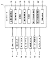
図1は、本発明の実施形態に係る作業機械の電気的構成及び油圧系統を概略的に示す全体図である。 FIG. 1 is an overall view schematically showing an electrical configuration and a hydraulic system of a work machine according to an embodiment of the present invention.
図1を参照して、例えば、油圧ショベルを代表とする作業機械には、図示は省略するが、上部旋回体(駆動対象物の一例)を下部走行体に対し旋回駆動するための油圧モータ2や、前記上部旋回体に設けられた作業アタッチメント(駆動対象物の一例)を起伏させるための油圧シリンダ3等を含むアクチュエータが設けられている。以下、これら油圧モータ2及び油圧シリンダ3をアクチュエータの一例として含む油圧系統を備えた作業機械について説明する。
Referring to FIG. 1, for example, a working machine represented by a hydraulic excavator is omitted in illustration, but a hydraulic motor 2 for driving the upper swing body (an example of a drive target) to swing relative to the lower traveling body. In addition, an actuator including a
作業機械は、油圧回路4と、エンジン5と、このエンジン5によって駆動される可変容量型の油圧ポンプ6と、この油圧ポンプ6から供給される作動油により駆動される前記油圧モータ2及び油圧シリンダ3と、前記油圧ポンプ6から吐出される作動油圧を検出する圧力センサ7と、これら油圧モータ2及び油圧シリンダ3に要求される動力に基づいてエンジン5の回転数を制御するコントローラ(エンジン制御装置)8と、このコントローラ8に接続された第一ダイヤル14及び第二ダイヤル15とを備えている。
The work machine includes a
前記油圧回路4は、前記油圧ポンプ6から吐出された作動油を前記油圧モータ2及び油圧シリンダ3に供給することが可能な油路と当該油圧モータ2及び油圧シリンダ3から排出された作動油をタンク25に回収するための油路とを適宜切換可能な切り換え弁を適所に備えたものである。また、油圧回路4は、オペレータの入力操作を受ける操作レバー9を備え、この操作レバー9はオペレータの入力操作に応じて前記油圧モータ2や油圧シリンダ3を駆動するための電気信号を前記コントローラ8に出力するようになっている。
The
前記エンジン5は、エンジン本体24と、このエンジン本体24に設けられたエンジン制御部10及び回転数センサ11とを備えている。エンジン本体24は、油圧ポンプ6を回転駆動可能となるように当該油圧ポンプ6に連結された出力軸24aを備えている。エンジン制御部10は、コントローラ8からの制御信号に応じて燃料噴射量を調整するようになっている。回転数センサ11は、前記出力軸24aの回転数を検出可能に構成されている。
The
油圧ポンプ6は、車軸式の可変容量型のポンプであり、その傾転を調整するためのレギュレータ12を備えている。このレギュレータ12は、前記コントローラ8に対し電気的に接続されている。
The
コントローラ8は、各種演算処理を実行するCPU、初期設定等を記憶するROM及び各種情報を一時的に記憶するためのRAM等から構成されるものである。このコントローラ8には、前記操作レバー9、圧力センサ7、第一ダイヤル14、第二ダイヤル15、回転数センサ11、エンジン制御部10及びレギュレータ12が電気的に接続されている。
The
図2は、コントローラの構成を機能的に示すブロック図である。 FIG. 2 is a block diagram functionally showing the configuration of the controller.
図2を参照して、コントローラ8は、目標流量演算部16と、差分演算部17と、記憶部18と、増加率演算部19と、判定部20と、第一回転数演算部21と、第二回転数演算部22と、駆動制御部23として機能する。
Referring to FIG. 2, the
記憶部18には、図7及び図8に示すように、現時点からT時間(第一時間)前までの第一経過期間における油圧ポンプ6の流量と、第一経過期間におけるエンジン5の回転数とが記憶されている。
As shown in FIGS. 7 and 8, the
目標流量演算部16は、前記操作レバー9によって入力された信号と、前記第一ダイヤル14によって入力されたアクセル指令信号と、圧力センサ7によって入力された油圧ポンプ6の吐出圧に関する信号とに基づいて現時点における目標流量Qrを算出する。この目標流量Qrは、前記記憶部18に記憶される。
The target flow
差分演算部17は、前記記憶部18に記憶された情報に基づいて、現時点からT時間前までの第一経過期間における流量の最大値Q(T)maxから第一経過時間における流量の最小値Q(T)min(図7参照)を減じた第一経過時間における最大変化流量ΔQ(T)(第一最大変化流量)を算出する。さらに、差分演算部17は、現時点から前記T時間よりも短いt時間(第二時間)前までの第二経過期間における流量の最大値Q(t)maxから第二経過期間における流量の最小値Q(t)minを減じた第二経過期間における最大変化流量ΔQ(t)(第二最大変化流量)を算出する。
Based on the information stored in the
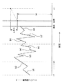
増加率演算部19は、前記第一経過期間におけるエンジン回転数の単位時間当たりの増加率の平均値Bを算出する。すなわち、この増加率演算部19では、図8に示すエンジン回転数の推移のうち、回転数が増加している区間b1〜b8を切り出して、この増加区間b1〜b8に基づいて単位時間当たりの回転数増加率平均値Bを算出する。
The increase
第一回転数演算部21は、下記式(1)を用いて、前記回転数増加率平均値Bに基づくt時間経過後の予想増加回転数ΔN(t)を算出する。
The first rotation
ΔN(t)=B×t ・・・(1)
さらに、第一回転数演算部21は、油圧ポンプ6の流量Qと油圧ポンプ6の傾転qとエンジン回転数Nとの関係式(2)を利用して、第一経過期間における流量の最大値Q(t)maxを、油圧ポンプ6の最大傾転qmaxと、t時間経過後の予想増加回転数ΔN(t)と、次の目標とすべき回転数N1との関係を下記式(3)のように表し、この式(3)を用いて下記式(4)に示すように前記回転数N1を算出する。
ΔN (t) = B × t (1)
Further, the first rotational
Q=q×N ・・・(2)
Q(t)max=qmax×{N1+ΔN(t)} ・・・(3)
N1={Q(t)max−qmax×ΔN(t)} ・・・(4)
この式(4)によって、油圧ポンプ6が第一経過期間における流量の最大値Q(t)maxをt時間経過後に最大傾転qmaxで吐出可能となる理想回転数N1(第一理想回転数)を算出することができる。
Q = q × N (2)
Q (t) max = qmax × {N1 + ΔN (t)} (3)
N1 = {Q (t) max−qmax × ΔN (t)} (4)
From this equation (4), the ideal rotation speed N1 (first ideal rotation speed) at which the
第二回転数演算部22は、目標流量Qrを、油圧ポンプ6が最大傾転qmaxで吐出するためのエンジン回転数N2(以下、最大傾転時回転数N2と称す)を下記式(5)によって算出する。
The second rotational
N2=Qr/qmax ・・・(5)
なお、最大傾転時回転数N2は、前記第一ダイヤル14によって入力された回転数に基づいて設定されるようにしてもよい。
N2 = Qr / qmax (5)
The maximum tilting rotation speed N2 may be set based on the rotation speed input by the
判定部20は、前記第一経過期間における最大変化流量ΔQ(T)に前記第二ダイヤル15によって入力された応答性係数Aを乗じた値と、前記第二経過期間における最大変化流量ΔQ(t)とを、下記式(6)を用いて比較する。
The
ΔQ(t)≧ΔQ(T)×A ・・・(6)
そして、判定部20は、前記式(6)を満たす場合に、油圧ポンプ6に要求される流量が急激に増大する可能性がある急負荷作業期間にあると判定し、前記式(6)を満たさないときに、通常の作業期間にあると判定する。
ΔQ (t) ≧ ΔQ (T) × A (6)
Then, the
さらに、判定部20は、前記急負荷作業期間にあると判定した場合に、前記理想回転数N1と最大傾転時回転数N2とを比較して、大きい回転数を急負荷時目標回転数として採用する。
Further, when the
駆動制御部23は、採用された目標回転数に基づいて、油圧ポンプ6の傾転及びエンジン5の燃料噴射流量を算出し、これらに対応する電気信号を前記エンジン制御部10及びレギュレータ12に出力するようになっている。
The
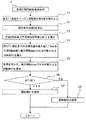
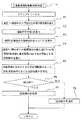
以下、前記コントローラ8により実行される処理を図3を用いて説明する。図3は、コントローラにより実行される処理を示すフローチャートである。
Hereinafter, processing executed by the
当該処理が開始されると、まず、現時点における作業状態の判定処理Uが実行される。この作業状態判定処理Uで急負荷作業期間にあると判定されると急負荷用回転数演算処理Vが実行される一方、前記作業状態判定処理Uで通常作業期間にあると判定されると通常回転数演算処理Oが実行される。 When the process is started, first, the current work state determination process U is executed. If it is determined that the work state determination process U is in the sudden load work period, the rapid load rotation speed calculation process V is executed. The rotational speed calculation process O is executed.
そして、これらの演算処理V、Oにより設定された目標回転数に基づいて、前記駆動制御部23により油圧ポンプ6の傾転及びエンジン5の燃料噴射流量が算出され、これらに対応する指令がエンジン制御部10及びレギュレータ12に出力される(ステップS1)。
Then, based on the target rotational speed set by these arithmetic processes V and O, the
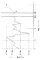
図4は、図3の作業状態判定処理Uの処理内容を示すフローチャートである。図7は、現時点からT時間前のポンプ流量の推移を示すグラフである。 FIG. 4 is a flowchart showing the processing contents of the work state determination processing U of FIG. FIG. 7 is a graph showing the transition of the pump flow rate T time before the present time.
図4及び図7を参照して、作業状態判定処理Uでは、まず、前記操作レバー9による入力信号と、第一ダイヤル14によるアクセル指令信号と、圧力センサ7によって入力された油圧ポンプ6の吐出圧とに基づいて現時点で要求されている目標流量Qrを算出して、これを記憶部18に記憶する(ステップU1)。
4 and 7, in the work state determination process U, first, the input signal from the
次いで、第二経過期間における流量の最大値Q(t)max及び最小値Q(T)minを記憶部18から読み出すとともに(ステップU2)、これらの値の差分である第二経過期間の最大変化流量ΔQ(t)を算出する(ステップU3)。 Next, the maximum value Q (t) max and the minimum value Q (T) min of the flow rate in the second elapsed period are read from the storage unit 18 (step U2), and the maximum change in the second elapsed period that is the difference between these values A flow rate ΔQ (t) is calculated (step U3).
次に、第一経過期間における流量の最大値Q(T)max及び最小値Q(T)minを記憶部18から読み出すとともに(ステップU4)、これらの値の差分である第一経過期間の最大変化流量ΔQ(T)を算出する(ステップU5)。 Next, the maximum value Q (T) max and the minimum value Q (T) min of the flow rate in the first elapsed period are read from the storage unit 18 (step U4), and the maximum of the first elapsed period, which is the difference between these values. The change flow rate ΔQ (T) is calculated (step U5).
そして、前記第二ダイヤル15による応答性係数Aが入力され(ステップU6)、この応答性係数Aを乗じた第一経過期間の最大変化流量ΔQ(T)と、前記第二経過期間の最大変化流量ΔQ(t)とを比較する(ステップU7)。
Then, the response coefficient A by the
すなわち、このステップU7では、図7に示すように、第一期間内で最も流量変化が大きかったときの期間(図示の例では2t〜tの期間)を急負荷期間にあるものと仮定して、このときの最大の流量幅ΔQ(T)に対し、現時点から直近の期間である第二経過期間(t〜現在までの期間)における流量幅ΔQ(t)がどれだけ近づいているのかを判定することにより、現在が急負荷期間にあるか否かを判定している。具体的に、本実施形態においては、応答性係数Aが0.8に設定されている。なお、本実施形態では、第一ダイヤル14により応答性係数Aを入力するようにしているが、記憶部18に予め応答性係数Aを記憶しておいてもよい。
That is, in this step U7, as shown in FIG. 7, it is assumed that the period when the flow rate change is greatest within the first period (the period of 2t to t in the illustrated example) is in the sudden load period. Determine how close the flow rate width ΔQ (t) in the second elapsed period (the period from t to the present) that is the most recent period from the maximum flow rate width ΔQ (T) at this time By doing so, it is determined whether or not the present is in the sudden load period. Specifically, in this embodiment, the response coefficient A is set to 0.8. In the present embodiment, the responsiveness coefficient A is input by the
また、前記ステップU7では、下記式(7)に基づいて急負荷作業期間にあるか否かを判定することもできる。 Moreover, in the said step U7, it can also be determined whether it exists in a sudden load work period based on following formula (7).
Q(T)max≧qmax×{Nqb+ΔN(t)}・・・(7)
ここで、Nqbは、例えば、目標流量Qrを油圧ポンプ6が最大傾転qmaxで吐出するためのエンジン回転数として予め算出されたものである。つまり、この不等式(7)を満たす場合には、予想増加回転数ΔN(t)だけエンジン回転数が増加するとともに油圧ポンプ6の傾転を最大qmaxにしても、第一経過期間における最大流量Q(T)maxを吐出させることができないため、急負荷作業期間にあると判定することができる一方、前記不等式(7)を満たさない場合には、予想増加回転数ΔN(t)だけエンジン回転数が増加すれば、油圧ポンプ6が最大傾転qmaxで前記最大流量Q(T)maxを吐出することができるため、通常作業期間にあると判定することができる。
Q (T) max ≧ qmax × {Nqb + ΔN (t)} (7)
Here, Nqb is calculated in advance as, for example, the engine speed for the
前記ステップU7において、急負荷作業期間にあると判定されると(ステップU7でYES)、前記急負荷用回転数演算処理Vが実行される一方、通常作業期間にあると判定されると(ステップU7でNO)、前記通常回転数演算処理Oが実行される。 If it is determined in step U7 that it is in the sudden load work period (YES in step U7), the sudden load rotation speed calculation process V is executed, while it is determined that it is in the normal work period (step). The normal rotational speed calculation process O is executed at NO in U7.
図5は、図3の急負荷用回転数演算処理Vの処理内容を示すフローチャートである。図8は、現時点からT時間前のエンジン回転数の推移を示すグラフである。 FIG. 5 is a flowchart showing the processing contents of the rapid load rotation speed calculation processing V of FIG. FIG. 8 is a graph showing the transition of the engine speed T time before the present time.
図5及び図8を参照して、急負荷用回転数演算処理Vでは、図8の区間b1〜b8に示すエンジン回転数の増加区間を記憶部18から読み出し(ステップV1)、これら増加区間b1〜b8に基づいて単位時間当たりの回転数増加率平均値Bを算出する(ステップV2)。 With reference to FIGS. 5 and 8, in the rapid load rotation speed calculation process V, the engine rotation speed increase sections shown in the sections b1 to b8 in FIG. 8 are read from the storage unit 18 (step V1), and these increase sections b1. Based on ˜b8, the average value B of the rotation speed increase rate per unit time is calculated (step V2).
次いで、この回転数増加率平均値Bに基づいてt時間後の予想増加回転数ΔN(t)を算出する(ステップV3)。具体的には、前記式(1)に示すように、回転数増加率平均値Bに対し時間tを乗じることにより予想増加回転数ΔN(t)を算出する。 Next, an expected increase rotational speed ΔN (t) after time t is calculated based on the average speed increase rate value B (step V3). Specifically, as shown in the equation (1), the expected increase rotational speed ΔN (t) is calculated by multiplying the rotational speed increase rate average value B by the time t.
次に、前記第一経過期間における流量の最大値Q(T)maxを、時間tの経過後に最大傾転qmaxで吐出可能となる理想回転数N1を前記式(4)に基づいて算出する(ステップV4)。つまり、このステップV4では、過去第一時間Tまで遡ったときの最大流量Q(T)maxが、この第一時間Tよりも短い第二時間tが経過した時点で要求されると想定した上で、前記回転数増加率平均値Bに従い増加した回転数によって、最大流量Q(T)maxを油圧ポンプ6が最大傾転qmaxで吐出可能となる現時点における理想回転数N1を算出することにより、実際に第二時間t経過後に最大流量Q(T)maxが要求された場合であっても、エンジン5の回転数の増加を、前記回転数増加率平均値Bに相当する増加、つまり、過去の実績ある回転数増加に抑えることを目的とした処理を行っている。
Next, the maximum value Q (T) max of the flow rate in the first elapsed period is calculated based on the equation (4) as an ideal rotation speed N1 that can be discharged at the maximum tilt qmax after the elapse of time t ( Step V4). That is, in this step V4, it is assumed that the maximum flow rate Q (T) max when going back to the past first time T is required when a second time t shorter than the first time T has elapsed. By calculating the ideal rotational speed N1 at which the
次いで、前記ステップU1で算出された目標流量Qrを、油圧ポンプ6が最大傾転qmaxで吐出するための最大傾転時回転数N2を算出する(ステップV5)。具体的には、前記式(5)によって算出される。
Next, the maximum tilt rotation speed N2 for the
そして、前記のように算出された理想回転数N1と最大傾転時回転数N2とを比較して(ステップV6)、より大きな回転数を急負荷時目標回転数として採用する(ステップV7、V8)。 Then, the ideal rotation speed N1 calculated as described above is compared with the maximum rotation speed N2 (step V6), and a larger rotation speed is adopted as the target rotation speed during a sudden load (steps V7, V8). ).
このようにより大きな回転数を採用するのは、回転数が大きい分だけ油圧ポンプ6の傾転を小さくすることができるので、以後、急激に目標流量が増大した場合であっても油圧ポンプ6の傾転調整によって流量変化に迅速に対応することができるようにするためである。すなわち、前記式(5)に示すように油圧ポンプ6の流量に対してポンプ傾転qとエンジン回転数Nとは反比例の関係にあるため、流量を一定とした場合、エンジン回転数を大きくするほど傾転を小さく抑えることができる。
Employing a larger rotational speed in this way can reduce the tilt of the
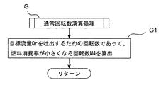
図6は、図3の通常回転数演算処理の処理内容を示すフローチャートである。 FIG. 6 is a flowchart showing the processing contents of the normal rotational speed calculation processing of FIG.
一方、前記通常回転数演算処理Oでは、目標流量Qrを前記油圧ポンプ6が最大傾転qmaxで吐出することができるエンジン5の回転数N2(最大傾転時回転数N2)を算出し、これを通常時目標回転数として採用する(ステップO1)。
On the other hand, in the normal rotational speed calculation process O, the rotational speed N2 of the engine 5 (maximum rotational speed N2) at which the
以上説明したように、本実施形態によれば、急負荷作業期間にあると判定された場合に設定される急負荷時目標回転数(N1又はN2)が、急負荷作業期間中にないと判定された通常時回転数(N2)以上の回転数に設定されるため、その分、通常作業時よりも油圧ポンプ6の傾転を小さく維持することができる。
As described above, according to the present embodiment, it is determined that the sudden load target rotation speed (N1 or N2) that is set when it is determined that there is a sudden load work period is not during the sudden load work period. Since the rotation speed is set to be equal to or higher than the normal rotation speed (N2), the tilt of the
そのため、本実施形態によれば、急負荷時作業期間中にはエンジン5の回転数をできるだけ大きく設定して、その分、油圧ポンプ6の傾転を小さく維持することにより、その後急激に目標流量が増大した場合にはポンプ傾転を大きくすることにより迅速な対応をすることができる。
Therefore, according to the present embodiment, the target flow rate is suddenly increased thereafter by setting the rotational speed of the
したがって、本実施形態によれば、目標流量が急激に増大した場合でも応答性の悪化を抑制することができる。 Therefore, according to the present embodiment, it is possible to suppress deterioration of responsiveness even when the target flow rate increases rapidly.
具体的に、前記実施形態では、図4のステップU7のように過去の第一経過期間中の最大変化流量ΔQ(T)と、この第一経過期間よりも短い期間である直近の第二経過期間中の最大変化流量ΔQ(t)とを比較することにより、急負荷期間にあるか否かを判定することができる。 Specifically, in the above-described embodiment, the maximum change flow rate ΔQ (T) during the past first elapsed period as in step U7 of FIG. 4 and the latest second period that is shorter than the first elapsed period. By comparing with the maximum change flow rate ΔQ (t) during the period, it can be determined whether or not it is in the sudden load period.
また、前記実施形態では、図5のステップV4のように、過去T時間の間に発生した最大流量Q(T)maxが、このT時間よりも短いt時間後の目標流量となった場合でも、この目標流量を、回転数増加率平均値Bに従って増加したエンジン回転数(N1+ΔN(t))によって油圧ポンプ6が最大傾転qmaxで吐出することができる理想回転数N1を算出することができるので、この理想回転数N1以上の回転数を現時点における目標回転数とすることにより、最大流量Q(T)maxをt時間経過後に吐出させる必要が生じた場合であっても、エンジン回転数の増加率を回転数増加率平均値B以下に抑えることができる。
Further, in the above embodiment, even when the maximum flow rate Q (T) max generated during the past T time becomes the target flow rate after t time shorter than this T time, as in step V4 of FIG. The ideal rotational speed N1 at which the
そして、前記実施形態では、急負荷作業期間にあると判定された場合に、図5のステップV6のように、前記理想回転数N1と、目標流量Qrを油圧ポンプ6が最大傾転qmaxで吐出可能となる最大傾転時回転数N2とを比較して大きい回転数を目標回転数に設定するようにしているので、急負荷時目標回転数が必要以上に大きくなるのを抑制することができ、燃料消費率の悪化を抑制することができる。
And in the said embodiment, when it determines with it being in a sudden load work period, like step V6 of FIG. 5, the
以下、別の実施形態について説明する。 Hereinafter, another embodiment will be described.
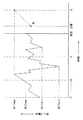
図13は、現時点からT時間前の油圧ポンプの動力の推移を示すグラフである。図14は、現時点からT時間前の油圧ポンプの吐出圧の推移を示すグラフである。 FIG. 13 is a graph showing changes in power of the hydraulic pump T time before the present time. FIG. 14 is a graph showing changes in the discharge pressure of the hydraulic pump T time before the present time.
図2、図13及び図14を参照して、本実施形態における記憶部18には、第一経過期間における油圧ポンプ6の動力と、第一経過期間におけるエンジン5の回転数(図8参照)とが記憶されている。なお、油圧ポンプ6の動力とは、油圧ポンプ6の流量と吐出圧とを乗じて得られるものであり、その結果として、前記記憶部18には、第一経過期間における油圧ポンプ6の流量及び吐出圧の推移も記憶されている。
Referring to FIGS. 2, 13, and 14, the
目標流量演算部16は、前記実施形態と同様に、操作レバー9及び第一ダイヤル14からの入力信号、及び圧力センサ7により検出された油圧ポンプ6の吐出圧に基づいて現時点における目標流量Qrを算出する。この目標流量Qrは、前記記憶部18に記憶される。
The target flow
また、目標流量演算部16は、前記目標流量Qrと、圧力センサ7により検出された油圧ポンプ6の吐出圧とを乗じることにより、現時点における目標動力Wrを算出する。
Further, the target flow
差分演算部17は、前記記憶部18に記憶された情報に基づいて、第一経過期間における動力の最大値W(T)maxから第一経過期間における動力の最小値W(T)minを減じた第一経過期間における最大変化動力ΔW(T)(第一変化動力)を算出する。さらに、差分演算部17は、現時点から前記T時間よりも短いt時間(第二時間)前までの第二経過時間における動力の最大値W(t)maxから第二経過期間における動力の最小値W(t)minを減じた第二経過期間における最大変化動力ΔW(t)(第二最大変化動力)を算出する。
The
増加率演算部19は、前記第一経過期間における油圧ポンプ6の吐出圧の単位時間当たりの増加率の平均値Cを算出する。すなわち、この増加率演算部19では、図14に示す油圧ポンプ6の吐出圧の推移のうち、吐出圧が増加している区間c1〜c8を切り出して、この増加区間c1〜c8に基づいて単位時間当たりの吐出圧増加率Cを算出する。
The increase
第一回転数演算部21は、下記式(8)を用いて、前記吐出圧増加率平均値Cに基づくt時間経過後の予想増加吐出圧ΔP(t)を算出する。
The first rotational
ΔP(t)=C×t ・・・(8)
また、第一回転数演算部21は、前記実施形態と同様に、前記式(1)を用いて、前記回転数増加率平均値Bに基づくt時間経過後の予想増加回転数ΔN(t)をも算出する。
ΔP (t) = C × t (8)
Further, similarly to the above-described embodiment, the first rotation
さらに、第一回転数演算部21は、油圧ポンプ6の吐出圧Pとエンジン回転数Nと油圧ポンプ6の傾転qと動力Wとの関係式(9)を利用して、第一経過期間における動力の最大値W(T)maxを、油圧ポンプ6の最大傾転qmaxと、t時間経過後の予想増加吐出圧ΔP(t)と、次の目標とすべき回転数N3と、圧力センサ7により検出された現時点での吐出圧Prと、前記予想増加回転数ΔN(t)の関係を下記式(10)のように表し、この式(10)を用いて下記式(11)に示すように回転数N3を算出する。
Further, the first rotational
W=P×q×N ・・・(9)
W(T)max=(Pr+ΔP(t))×qmax×(N3+ΔN(t))・・・(10)
N3=W(T)max/[{Pr+ΔP(t)}×qmax]−ΔN(t)・・・(11)
この式(11)によって、油圧ポンプ6が第一経過期間における動力の最大値W(T)maxをt時間経過後に最大傾転qmaxで出力可能となる理想回転数N3(第二理想回転数)を算出することができる。
W = P × q × N (9)
W (T) max = (Pr + ΔP (t)) × qmax × (N3 + ΔN (t)) (10)
N3 = W (T) max / [{Pr + ΔP (t)} × qmax] −ΔN (t) (11)
According to this equation (11), the ideal rotational speed N3 (second ideal rotational speed) at which the
第二回転数演算部22は、前記油圧ポンプ6に目標流量Qrを吐出させるためのエンジン5の回転数であって、燃料消費率ができるだけ小さくなる回転数N4(以下、小燃費回転数N4と称す)を算出する。例えば、第二回転数演算部22は、油圧ポンプ6に目標流量Qrを吐出させるために必要なエンジン5の動力(馬力)を算出し、この動力を出力するためのエンジン回転数を図9に示すようなマップに基づいて特定する。具体的に、マップには、等燃費線と等馬力線とが設定されており、これら両線の交点D1、D2のうちエンジン回転数がより小さくなるもの(図示の例ではD1)が前記第二回転数演算部22によって特定される。なお、同図からも明らかなように、特定の馬力を出力するのに当たってはエンジン回転数を小さくするほど燃費が向上する傾向にある。
The second rotational
判定部20は、前記第一経過期間における最大変化動力ΔW(T)に前記第二ダイヤル15によって入力された応答性係数Aを乗じた値と、第二経過期間における最大変化動力ΔW(t)とを、下記式(12)を用いて比較する。
The
ΔW(t)≧ΔW(T)×A ・・・(12)
そして、判定部20は、前記式(12)を満たす場合に、油圧ポンプ6に要求される動力が急激に増大する可能性がある急負荷作業期間にあると判定し、前記式(12)を満たさないときに、通常の作業期間にあると判定する。
ΔW (t) ≧ ΔW (T) × A (12)
Then, the
さらに、判定部20は、前記急負荷作業期間にあると判定した場合に、前記理想回転数N3と小燃費回転数N4とを比較して、大きい回転数を目標回転数として採用する。
Further, when the
以下、前述した本実施形態に係るコントローラ8により実行される処理を説明する。
Hereinafter, processing executed by the
図示は省略するが、本実施形態に係るコントローラ8による処理の全体的な流れは、前記実施形態と同様である。すなわち、処理が開始されると、まず、現時点における作業状態の判定処理Xが実行される。この作業状態判定処理Xで急負荷作業期間にあると判定されると急負荷用回転数演算処理Fが実行される一方、前記作業状態判定処理Xで通常作業期間にあると判定されると通常回転数演算処理Gが実行される(図2参照)。
Although not shown, the overall flow of processing by the
そして、これらの演算処理F、Gにより設定目標回転数に基づいて、前記駆動制御部23により油圧ポンプ6の傾転及びエンジン5の燃料噴射量が算出され、これらに対応する指令がエンジン制御部10及びレギュレータ12に出力される(ステップS1に相当)。
Then, the
図10は、別の実施形態に係る作業状態判定処理Xの処理内容を示すフローチャートである。 FIG. 10 is a flowchart showing the processing contents of the work state determination processing X according to another embodiment.
図10及び図13を参照して、作業状態判定処理Xでは、まず、前記操作レバー9による入力信号と、第一ダイヤル14によるアクセル指令信号と、圧力センサ7によって入力された油圧ポンプ6の吐出圧とに基づいて目標流量Qr及び目標動力Wrを算出して、これらを記憶部18に記憶する(ステップX1)。
With reference to FIGS. 10 and 13, in the work state determination process X, first, the input signal from the
次いで、第二経過期間における動力の最大値W(t)max及び最小値W(t)minを記憶部18から読み出すとともに(ステップX2)、これらの値の差分である第二経過期間の最大変化動力ΔW(t)を算出する(ステップX3)。 Next, the maximum value W (t) max and the minimum value W (t) min of the power in the second elapsed period are read from the storage unit 18 (step X2), and the maximum change in the second elapsed period, which is the difference between these values. The power ΔW (t) is calculated (step X3).
次に、第一経過期間における動力の最大値W(T)max及び最小値W(T)minを記憶部18から読み出すとともに(ステップX4)、これらの値の差分である第一経過期間の最大変化動力ΔW(T)を算出する(ステップX5)。 Next, the maximum value W (T) max and the minimum value W (T) min of the power in the first elapsed period are read from the storage unit 18 (step X4), and the maximum of the first elapsed period, which is the difference between these values. The change power ΔW (T) is calculated (step X5).
そして、前記第二ダイヤル15による応答性係数Aが入力され(ステップX6)、この応答性係数Aを乗じた第一経過期間の最大変化動力ΔW(T)と、第二経過期間の最大変化動力W(t)とを比較する(ステップX7)。
Then, the response coefficient A by the
すなわち、このステップX7では、図13に示すように、第一期間内で最も動力変化が大きかったときの期間(図示の例では2t〜tの期間)を急負荷期間にあるものと仮定して、このときの動力幅ΔW(T)に対し、現時点から直近の期間(図示の例ではt〜現在)である第二経過期間における動力幅ΔW(t)がどれだけ近づいているのかを判定することにより、現在が急負荷期間にあるか否かを判定している。具体的に、本実施形態においては、応答性係数Aが0.8に設定されている。 That is, in step X7, as shown in FIG. 13, it is assumed that the period when the power change is the largest in the first period (the period of 2t to t in the illustrated example) is in the sudden load period. Then, it is determined how close the power width ΔW (t) in the second elapsed period, which is the most recent period from the present time (t to present in the illustrated example), to the power width ΔW (T) at this time. Thus, it is determined whether or not the present is in the sudden load period. Specifically, in this embodiment, the response coefficient A is set to 0.8.
また、前記ステップX7では、下記式(13)に基づいて急負荷作業期間にあるか否かを判定することもできる。 In Step X7, it can also be determined whether or not it is in a sudden load work period based on the following equation (13).
W(T)max≧Pr×qmax×{Nwb+ΔN(t)}・・・(13)
ここで、Prは、圧力センサ7により検出された油圧ポンプ6の吐出圧であり、Nwbとしては、例えば、前記理想回転数N3と同様に、油圧ポンプ6に目標流量Qrを吐出させるためのエンジン5の回転数であって、燃料消費率ができるだけ小さくなる回転数が採用される。つまり、この不等式(13)を満たす場合には、予想増加回転数ΔN(t)だけエンジン回転数が増加するとともに油圧ポンプ6の傾転を最大qmaxとしても、第一経過期間における最大動力W(T)maxを出力することができないため、急負荷作業期間にあると判定することができる一方、前記不等式(13)を満たさない場合には、予想増加回転数ΔN(t)だけエンジン回転数が増加すれば、油圧ポンプ6が最大傾転qmaxで最大動力W(T)maxを出力することができるため、通常作業期間にあると判定することができる。
W (T) max ≧ Pr × qmax × {Nwb + ΔN (t)} (13)
Here, Pr is the discharge pressure of the
前記ステップX7において、急負荷作業期間にあると判定されると(ステップX7でYES)、前記急負荷用回転数演算処理Fが実行される一方、通常作業期間にあると判定されると(ステップX7でNO)、前記通常回転数演算処理Gが実行される。 If it is determined in step X7 that the vehicle is in the sudden load work period (YES in step X7), the sudden load rotation speed calculation process F is executed, while it is determined that it is in the normal work period (step). X7, NO), the normal rotational speed calculation process G is executed.
図11及び図14を参照して、急負荷用回転数演算処理Fでは、まず、前記実施形態のステップV1〜V3を実行することにより、時間t経過後の予想増加回転数ΔN(t)を算出する。 Referring to FIGS. 11 and 14, in the sudden load rotational speed calculation process F, first, the predicted increased rotational speed ΔN (t) after the elapse of time t is obtained by executing steps V1 to V3 of the embodiment. calculate.
そして、図14の区間c1〜c8に示すポンプ吐出圧の増加区間を記憶部18から読み出し(ステップF1)、これら増加区間c1〜c8に基づいて単位時間当たりの吐出圧増加率平均値Cを算出する(ステップF2)。 And the increase area of the pump discharge pressure shown to the area c1-c8 of FIG. 14 is read from the memory | storage part 18 (step F1), and the discharge pressure increase rate average value C per unit time is calculated based on these increase areas c1-c8. (Step F2).
次いで、この吐出圧増加率平均値Cに基づいてt時間後の予想増加吐出圧ΔP(t)を算出する(ステップF3)。具体的には、前記式(8)吐出圧増加率平均値Cに時間tを乗じることにより予想増加吐出圧ΔP(t)を算出する。 Next, the expected increase discharge pressure ΔP (t) after t time is calculated based on the average value C of the discharge pressure increase rate (step F3). Specifically, the expected increase discharge pressure ΔP (t) is calculated by multiplying the above equation (8) discharge pressure increase rate average value C by time t.
次に、前記第一経過期間における油圧ポンプ6の動力の最大値W(T)maxを、時間tの経過後に最大傾転qmaxで出力可能となる理想回転数N3を前記式(11)に基づいて算出する(ステップF4)。つまり、このステップF4では、過去第一時間Tまで遡ったときの最大動力W(T)maxが、この第一時間Tよりも短い第二時間tが経過した時点で要求されると想定した上で、前記吐出圧増加率平均値Cに従い増加した吐出圧及び前記回転数増加率平均値Bに従い増加した回転数によって、最大動力W(T)maxを油圧ポンプ6が最大傾転qmaxで吐出可能となる理想回転数N3を算出することにより、実際に第二時間t経過後に最大動力W(T)maxが要求された場合であっても、エンジン5の回転数の増加は、前記回転数増加率平均値Bに相当する増加、つまり、過去の実績のある回転数増加に抑えることができる。
Next, based on the above equation (11), the maximum value W (T) max of the power of the
次いで、前記ステップX1で算出された目標流量Qrを吐出するための回転数であって、エンジン5の燃料消費率が小さくなる小燃費回転数N4を算出する(ステップF5)。具体的には、図9に示す等燃費線と等馬力線との交点D1、D2のうち、エンジン回転数が小さいものが特定される。
Next, the engine speed for discharging the target flow rate Qr calculated in the step X1 and the fuel efficiency rate N4 for reducing the fuel consumption rate of the
そして、前記のように算出された理想回転数N3と小燃費回転数N4とを比較して(ステップF6)、より大きな回転数を目標回転数として採用する(ステップF7、F8)。このように大きな回転数を採用するのは、回転数が大きい分だけ油圧ポンプ6の傾転を小さくすることができるので、以後、急激に目標流量が増大した場合であっても油圧ポンプ6の傾転調整によって流量変化に迅速に対応することができるようにするためである。
Then, the ideal rotation speed N3 calculated as described above is compared with the low fuel consumption rotation speed N4 (step F6), and a larger rotation speed is adopted as the target rotation speed (steps F7, F8). By adopting such a large rotational speed, the tilt of the
一方、前記通常回転数演算処理Gでは,前記油圧ポンプ6に目標流量Qrを吐出させるためのエンジン5の回転数であって、燃料消費率ができるだけ小さくなる小燃費回転数N4を算出し、これを目標回転数として採用する(ステップG1)。
On the other hand, in the normal rotational speed calculation process G, the rotational speed of the
以上説明したように、前記実施形態によれば、図10のステップX7に示すように第一経過期間における最大変化動力ΔW(T)と、第二経過期間における最大変化動力ΔW(t)とを利用して、急負荷作業期間にあるか否かを判定することができる。 As described above, according to the embodiment, the maximum change power ΔW (T) in the first elapsed period and the maximum change power ΔW (t) in the second elapsed period as shown in Step X7 of FIG. It can be used to determine whether or not it is in a sudden load work period.
また、前記実施形態によれば、図8のステップF4に示すように過去T時間の間に発生した最大動力W(T)maxが、このT時間よりも短いt時間経過後の目標動力となった場合でも、この目標動力を、回転数増加率平均値Bに従って増加したエンジン回転数、及び吐出圧増加率平均値に従って増加した吐出圧によって油圧ポンプ6が最大傾転qmaxで出力することができる現時点の理想回転数N3を算出することができるので、この理想回転数N3以上の回転数を現時点における目標回転数とすることにより、前記最大動力W(T)maxをt時間経過後に出力させる必要が生じた場合であっても、エンジン回転数の増加率を第一経過期間における回転数増加率平均値B以下に抑えることができる。
Further, according to the embodiment, as shown in step F4 of FIG. 8, the maximum power W (T) max generated during the past T time becomes the target power after elapse of t time shorter than this T time. Even in this case, the
そして、前記実施形態では、図11のステップF6に示すように急負荷期間にあると判定された場合に、理想回転数N3及び小燃費回転数N4のうち大きなものを目標回転数として設定することができるので、目標回転数が必要以上に大きくなるのを抑制することができ、燃料消費率の悪化を抑制することができる。 And in the said embodiment, when it determines with it being in a sudden load period as shown to step F6 of FIG. 11, larger one of the ideal rotation speed N3 and the fuel-efficient rotation speed N4 is set as a target rotation speed. Therefore, it is possible to suppress the target rotational speed from becoming larger than necessary, and to suppress deterioration of the fuel consumption rate.
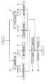
なお、前記各実施形態で実行される処理を図15に示すように並行して行うこともできる。 Note that the processing executed in each of the embodiments can be performed in parallel as shown in FIG.
具体的には、前記作業状態判定処理UとXとをそれぞれ実行するとともに、この判定処理U、Xごとにその判定結果に応じて急負荷用回転数演算処理V、F又は通常回転数演算処理O、Gをそれぞれ実行し、急負荷用回転数演算処理V、Fの双方が実行された場合には、それぞれの処理V、Fで採用されたエンジン回転数N1〜N4のうち一番回転数の高いものを採用する(ステップS0)。 Specifically, the work state determination processes U and X are executed, respectively, and each of the determination processes U and X, depending on the determination result, the rapid load rotation speed calculation processes V and F or the normal rotation speed calculation process. When both O and G are executed and both of the rapid load speed calculation processes V and F are executed, the engine speed N1 to N4 employed in the processes V and F is the highest speed. The one having a higher value is adopted (step S0).
前記実施形態によれば、将来の目標流量を想定して算出された理想回転数N1(第一理想回転数)、将来の油圧ポンプ6の動力を想定して算出された理想回転数N3(第二理想回転数)、前記最大傾転回転数N2、及び小燃費回転数N4のうちの一番回転数の高いものを目標回転数として設定することができるので、将来の目標流量及び動力を確実に確保しながら、これらを確保するためのエンジン回転数の増加率をできるだけ小さく抑えることにより、応答性の悪化を抑制することができる。
According to the embodiment, the ideal rotation speed N1 (first ideal rotation speed) calculated assuming the future target flow rate, and the ideal rotation speed N3 (first rotation) calculated assuming the power of the
B 回転数増加率平均値
C 吐出圧増加率平均値
F、V 急負荷用回転数演算処理
G、O 通常回転数演算処理
U、X 作業状態判定処理
T 第一時間
t 第二時間
N1、N3 理想回転数
N2 最大傾転回転数
N4 小燃費回転数
1 エンジン制御装置
2 油圧モータ(アクチュエータ)
3 油圧シリンダ(アクチュエータ)
5 エンジン
6 油圧ポンプ
7 圧力センサ
8 コントローラ(制御部)
16 目標流量演算部
17 差分演算部
18 記憶部
19 増加率演算部
20 判定部
21 第一回転数演算部
22 第二回転数演算部
B Rotational speed increase rate average value C Discharge pressure increase rate average value F, V Rapid load rotational speed calculation processing G, O Normal rotational speed calculation processing U, X Work state determination processing T First time t Second time N1, N3 Ideal rotation speed N2 Maximum tilt rotation speed N4 Low fuel
3 Hydraulic cylinder (actuator)
5
16 target flow
Claims (12)
前記アクチュエータに要求される作動油流量に基づいてエンジンの目標回転数を設定する回転数設定手段と、
この回転数設定手段により設定された目標回転数に基づいて前記エンジンの回転数を調整する回転数調整手段と、
前記アクチュエータに要求される作動油流量が急激に増加する可能性のある急負荷作業の期間中にあるか否かを判定する作業状態判定手段とを備え、
前記回転数設定手段は、前記作業状態判定手段により急負荷作業期間中にはないと判定された場合には通常時目標回転数を設定する一方、前記作業状態判定手段により急負荷作業期間中にあると判定された場合には前記通常時目標回転数以上の急負荷時目標回転数を設定することを特徴とするエンジン制御装置。 An engine, a variable displacement hydraulic pump driven by the engine, an actuator driven by hydraulic oil supplied from the hydraulic pump, and the hydraulic pump for discharging the hydraulic oil flow rate required for the actuator The engine control device is provided in a work machine including an adjusting means for adjusting the tilt of the engine according to the engine speed, and controls the engine speed based on a hydraulic oil flow rate required for the actuator. And
A rotational speed setting means for setting a target rotational speed of the engine based on a hydraulic oil flow rate required for the actuator;
A rotational speed adjusting means for adjusting the rotational speed of the engine based on the target rotational speed set by the rotational speed setting means;
Working state determination means for determining whether or not the hydraulic fluid flow rate required for the actuator is during a period of sudden load work that may increase rapidly,
The rotation speed setting means sets the normal target rotation speed when the work state determination means determines that it is not during the sudden load work period, while the work state determination means sets the target rotation speed during the heavy load work period. An engine control device characterized in that, when it is determined that there is an engine speed, a target rotational speed at a sudden load equal to or higher than the normal target rotational speed is set.
Priority Applications (1)
| Application Number | Priority Date | Filing Date | Title |
|---|---|---|---|
| JP2008130842A JP2009281149A (en) | 2008-05-19 | 2008-05-19 | Engine control device and working machine equipped with the same |
Applications Claiming Priority (1)
| Application Number | Priority Date | Filing Date | Title |
|---|---|---|---|
| JP2008130842A JP2009281149A (en) | 2008-05-19 | 2008-05-19 | Engine control device and working machine equipped with the same |
Publications (1)
| Publication Number | Publication Date |
|---|---|
| JP2009281149A true JP2009281149A (en) | 2009-12-03 |
Family
ID=41451874
Family Applications (1)
| Application Number | Title | Priority Date | Filing Date |
|---|---|---|---|
| JP2008130842A Pending JP2009281149A (en) | 2008-05-19 | 2008-05-19 | Engine control device and working machine equipped with the same |
Country Status (1)
| Country | Link |
|---|---|
| JP (1) | JP2009281149A (en) |
Cited By (7)
| Publication number | Priority date | Publication date | Assignee | Title |
|---|---|---|---|---|
| JP2011236751A (en) * | 2010-05-06 | 2011-11-24 | Hitachi Constr Mach Co Ltd | Prime mover revolution speed control system for hydraulic construction machine |
| WO2013067801A1 (en) * | 2011-11-08 | 2013-05-16 | 湖南三一智能控制设备有限公司 | Control method and device for automatically calibrating rotational speed of digger |
| WO2013089230A1 (en) * | 2011-12-16 | 2013-06-20 | キャタピラー エス エー アール エル | Hydraulic machinery |
| KR20160133321A (en) * | 2015-05-12 | 2016-11-22 | 두산인프라코어 주식회사 | Methodof controlling wheel loader |
| JPWO2017115837A1 (en) * | 2015-12-28 | 2018-10-25 | 住友建機株式会社 | Excavator |
| CN108779614A (en) * | 2016-05-26 | 2018-11-09 | 日立建机株式会社 | Work machine |
| US11339554B2 (en) * | 2017-04-21 | 2022-05-24 | Deere & Company | Method for controlling the engine speed of a utility vehicle |
-
2008
- 2008-05-19 JP JP2008130842A patent/JP2009281149A/en active Pending
Cited By (13)
| Publication number | Priority date | Publication date | Assignee | Title |
|---|---|---|---|---|
| US8583332B2 (en) | 2010-05-06 | 2013-11-12 | Hitachi Construction Machinery Co., Ltd. | Prime mover revolution speed control system for hydraulic construction machine |
| JP2011236751A (en) * | 2010-05-06 | 2011-11-24 | Hitachi Constr Mach Co Ltd | Prime mover revolution speed control system for hydraulic construction machine |
| WO2013067801A1 (en) * | 2011-11-08 | 2013-05-16 | 湖南三一智能控制设备有限公司 | Control method and device for automatically calibrating rotational speed of digger |
| CN104136782B (en) * | 2011-12-16 | 2016-03-30 | 卡特彼勒Sarl公司 | Hydraulic machine |
| JP2013124752A (en) * | 2011-12-16 | 2013-06-24 | Caterpillar Sarl | Hydraulic working machine |
| CN104136782A (en) * | 2011-12-16 | 2014-11-05 | 卡特彼勒Sarl公司 | Hydraulic machinery |
| WO2013089230A1 (en) * | 2011-12-16 | 2013-06-20 | キャタピラー エス エー アール エル | Hydraulic machinery |
| KR20160133321A (en) * | 2015-05-12 | 2016-11-22 | 두산인프라코어 주식회사 | Methodof controlling wheel loader |
| KR102452811B1 (en) | 2015-05-12 | 2022-10-11 | 현대두산인프라코어 주식회사 | Methodof controlling wheel loader |
| JPWO2017115837A1 (en) * | 2015-12-28 | 2018-10-25 | 住友建機株式会社 | Excavator |
| CN108779614A (en) * | 2016-05-26 | 2018-11-09 | 日立建机株式会社 | Work machine |
| CN108779614B (en) * | 2016-05-26 | 2021-03-26 | 日立建机株式会社 | Working machine |
| US11339554B2 (en) * | 2017-04-21 | 2022-05-24 | Deere & Company | Method for controlling the engine speed of a utility vehicle |
Similar Documents
| Publication | Publication Date | Title |
|---|---|---|
| JP2009281149A (en) | Engine control device and working machine equipped with the same | |
| JP4440271B2 (en) | Engine output control device and engine output control method for work vehicle | |
| JP4489697B2 (en) | Engine control device for construction machinery | |
| JP5585488B2 (en) | Power source device for hybrid construction machinery | |
| EP2851475B1 (en) | Hybrid construction machinery | |
| JP5696212B2 (en) | Hydraulic pump control system for construction machinery | |
| US20170037790A1 (en) | Device for controlling engine and hydraulic pump of construction equipment and control method therefor | |
| JP2005061322A (en) | Control device of working vehicle | |
| JP2005083344A (en) | Fan rotational frequency control method | |
| KR20110073082A (en) | Hydraulic pump control apparatus and control method for construction machinery | |
| US20160340871A1 (en) | Engine and Pump Control Device and Working Machine | |
| JP5585487B2 (en) | Power source device for hybrid construction machinery | |
| JP6480368B2 (en) | Work vehicle | |
| JP2010276126A (en) | Control device and working machine having the same | |
| JP4865739B2 (en) | Output torque assist system for hybrid construction machines | |
| JP2009074406A (en) | Engine controller | |
| JP2012202219A (en) | Hydraulic circuit of work machine | |
| JPWO2016047167A1 (en) | Work machine display | |
| JP4115994B2 (en) | Construction machine control device and input torque calculation method | |
| JP4884124B2 (en) | Hydraulic control circuit for construction machinery | |
| JP4705598B2 (en) | Engine speed control device for construction machinery | |
| JP5124656B2 (en) | Engine output control device | |
| JP2005061298A (en) | Construction machine | |
| JP2001329883A (en) | Engine control device for construction machine | |
| JP2009197609A (en) | Monitoring device of construction machine |