JP2009280194A - Instrument panel device - Google Patents

Instrument panel device Download PDF

Info

Publication number
JP2009280194A
JP2009280194A JP2008332403A JP2008332403A JP2009280194A JP 2009280194 A JP2009280194 A JP 2009280194A JP 2008332403 A JP2008332403 A JP 2008332403A JP 2008332403 A JP2008332403 A JP 2008332403A JP 2009280194 A JP2009280194 A JP 2009280194A
Authority
JP
Japan
Prior art keywords
instrument panel
width direction
vehicle width
vehicle
driver
Prior art date
Legal status (The legal status is an assumption and is not a legal conclusion. Google has not performed a legal analysis and makes no representation as to the accuracy of the status listed.)
Pending
Application number
JP2008332403A
Other languages
Japanese (ja)
Inventor
雅年 ▲高▼山
Masatoshi Takayama
Toshinori Toyohara
利憲 豊原
Kazuhiro Tanaka
一洋 田中
Kazunori Ikura
和徳 居倉
Yasuaki Okazaki
安昭 岡崎
Hitoshi Ochimizu
均 落水
Current Assignee (The listed assignees may be inaccurate. Google has not performed a legal analysis and makes no representation or warranty as to the accuracy of the list.)
Mazda Motor Corp
Original Assignee
Mazda Motor Corp
Priority date (The priority date is an assumption and is not a legal conclusion. Google has not performed a legal analysis and makes no representation as to the accuracy of the date listed.)
Filing date
Publication date
Application filed by Mazda Motor Corp filed Critical Mazda Motor Corp
Priority to JP2008332403A priority Critical patent/JP2009280194A/en
Priority to EP09004405A priority patent/EP2112013A1/en
Priority to US12/426,387 priority patent/US20090261612A1/en
Publication of JP2009280194A publication Critical patent/JP2009280194A/en
Pending legal-status Critical Current

Links

Images

Abstract

<P>PROBLEM TO BE SOLVED: To provide an instrument panel device capable of effectively using an internal space and an upper space of an instrument panel without causing any problem such as degradation of the visibility in the front view of a vehicle. <P>SOLUTION: The instrument panel device of an automobile comprises an instrument panel body 1 arranged in a front part of a cabin, a display indication portion 5 for displaying information related to on-vehicle apparatuses. By connecting a center console part 2 to a center portion in the vehicle width direction of the instrument panel body 1, an instrument-panel backwardly inclined surface part is formed, in which the center portion in the vehicle width direction is located most backwardly. An instrument panel raised part 23 is formed on an upper surface part 7 of the instrument panel body 1, in which a part from the center portion in the vehicle width direction to an end on a driver's seat side is raised upwardly. Further, a stepped part 23 extending downwardly from its rear end is formed, and the display indication portion 5 is arranged on an inclined part 23b of the stepped part 23, which is located on the front side of the center console part 2 to direct the driver's seat side. <P>COPYRIGHT: (C)2010,JPO&INPIT

Description

本発明は、車室前部に配設されて車体の後方側に膨出しつつ車幅方向に延在されたインストルメントパネル装置に関するものである。   The present invention relates to an instrument panel device that is disposed in a front part of a passenger compartment and bulges toward the rear side of a vehicle body and extends in the vehicle width direction.

従来、下記特許文献1に示されるように、インパネ本体の前上部および後下部にそれぞれ上部メータおよび下部メータを支持し、インパネ本体に上部メータおよび下部メータの周囲を囲むように上部パネルおよび下部パネルを着脱自在に固定した自動車のインストルメントパネル構造において、上部メータおよび下部メータをそれぞれステアリングホイールの上半部の上側および下側に配設し、上記上部パネルの上縁をステアリングホイールの上半部に概ね沿う形状としたものが知られている。
特開2005−297657号公報
Conventionally, as shown in Patent Document 1 below, an upper panel and a lower meter are respectively supported on the front upper part and the rear lower part of the instrument panel body, and the upper panel and the lower panel are surrounded by the instrument panel body so as to surround the upper meter and the lower meter. In the instrument panel structure of an automobile in which the detachable is fixed, the upper meter and the lower meter are respectively arranged above and below the upper half of the steering wheel, and the upper edge of the upper panel is the upper half of the steering wheel. A shape generally conforming to the above is known.
JP 2005-297657 A

上記特許文献1に開示された自動車のインストルメントパネル構造では、ステアリングホイールの上半部の上側および下側にそれぞれ上部メータおよび下部メータを配設したため、ステアリングホイールに邪魔されずに上記各メータをそれぞれ視認できるという利点がある。この反面、各メータの視認性を確保し得るようにその大きさを設定した場合には、このメータ配設部の上端位置が高くなることが避けられず、その影響を受けて車両の前方視界に対する見切り性が低下したり、運転者が圧迫感を受けたりする等の問題がある。   In the vehicle instrument panel structure disclosed in Patent Document 1, the upper meter and the lower meter are disposed on the upper and lower sides of the upper half of the steering wheel, respectively. Each has the advantage of being visible. On the other hand, when the size of each meter is set so that the visibility of each meter can be ensured, it is inevitable that the upper end position of the meter mounting portion is increased. There are problems such as a decrease in the ability to give up and a feeling of pressure on the driver.

また、上記特許文献1に係る発明では、車室前方に位置するフロントウインドを介して前方を視認した状態にある運転者が、上記上部メータおよび下部メータの両方を視認しようとした場合、この上部メータおよび下部メータが上下に連続して見えるため、その表示内容を迅速かつ適正に確認することが困難であるという問題があり、かつ上記インストルメントパネルの上部空間および内部空間を有効利用に利用する点について、上記特許文献1に係る発明では何ら考慮されていなかった。   Further, in the invention according to Patent Document 1, when a driver who is viewing the front through a front window located in front of the passenger compartment tries to visually recognize both the upper meter and the lower meter, Since the meter and the lower meter appear to be continuous vertically, there is a problem that it is difficult to confirm the display contents quickly and properly, and the upper space and the internal space of the instrument panel are used for effective use. Regarding the point, the invention according to Patent Document 1 has not been considered at all.

本発明は、上記の問題点に鑑みてなされたものであり、車両の前方視界における見切り性が低下する等の問題を生じることなく、インストルメントパネルに設けられた画面表示部の視認性を確保できるとともに、インストルメントパネルの内部空間および上部空間を有効に利用することができるインストルメントパネル装置を提供することを目的としている。   The present invention has been made in view of the above-described problems, and ensures the visibility of the screen display unit provided on the instrument panel without causing problems such as a drop in the parting ability in the front field of view of the vehicle. An object of the present invention is to provide an instrument panel device that can effectively use the internal space and the upper space of the instrument panel.

請求項1に係る発明は、車室前部に配設されて車体の後方側に膨出しつつ車幅方向に延在されたインパネ本体と、車載機器に関連した情報を表示する画面表示部とを有する自動車のインストルメントパネル装置であって、上記インパネ本体の車幅方向中央部に車載機器の操作部を有するセンタコンソール部が接続されることにより、車幅方向に連続しつつ緩やかに下方に傾斜するとともに平面視で車幅方向の中央部が最も後方に位置するように湾曲したインパネ後方傾斜面部が形成され、上記インパネ本体の上面部には、車幅方向の中央部から運転席側の端部に亘る部位を上方に隆起させたインパネ隆起部が形成されるとともに、その後端部から下方に延びる段差部が形成され、この段差部のうち上記センタコンソール部の前方側に位置して、運転席側を指向するように傾斜した部位に上記画面表示部が配設されたものである。   The invention according to claim 1 is an instrument panel body which is disposed in the front part of the passenger compartment and extends in the vehicle width direction while bulging to the rear side of the vehicle body, and a screen display unit which displays information related to the in-vehicle device. An instrument panel device for an automobile having a center console portion having an operation portion of an in-vehicle device connected to a central portion in the vehicle width direction of the instrument panel main body, so that the instrument panel device is gently lowered downward while being continuous in the vehicle width direction. An instrument panel rear inclined surface portion that is inclined and curved so that the center portion in the vehicle width direction is located at the rearmost position in a plan view is formed on the upper surface portion of the instrument panel body from the center portion in the vehicle width direction to the driver seat side. An instrument panel raised portion is formed by raising the portion extending over the end portion upward, and a step portion extending downward from the rear end portion is formed, and the step portion is located on the front side of the center console portion. The driver's seat side inclined portion to direct one in which the screen display unit is disposed.

請求項2に係る発明は、上記請求項1記載のインストルメントパネル装置において、上記インパネ隆起部の後端部に設けられた段差部がインパネ本体の車幅方向中央部から運転席側端部に亘るように延設されるとともに、上記段差部とインパネ後方傾斜面部との間にインパネ底部が形成され、このインパネ底部上でステアリングホイールの前方位置にメータクラスタ部の計器盤面部が配設されたものである。   According to a second aspect of the present invention, in the instrument panel device according to the first aspect, the step provided at the rear end portion of the instrument panel raised portion extends from the vehicle width direction central portion of the instrument panel body to the driver seat side end portion. An instrument panel bottom is formed between the stepped portion and the instrument panel rear inclined surface, and an instrument panel surface of the meter cluster unit is disposed at a front position of the steering wheel on the instrument panel bottom. Is.

請求項3に係る発明は、上記請求項2に記載のインストルメントパネル装置において、上記メータクラスタ部が、インパネ底部に連設されて上方に膨出するよう設置されたメータフード部と、このメータフード部の下方に配設されて運転席側を指向する計器盤面部とを有し、上記メータフード部の前端部に前突状の湾曲部が設けられてこの湾曲部がインパネ底部に連設されるとともに、上記メータクラスタ部の左右両側方部を囲繞するようにインパネ底部が配設されたものである。   According to a third aspect of the present invention, in the instrument panel device according to the second aspect, the meter cluster unit is connected to the bottom of the instrument panel so as to bulge upward, and the meter hood unit. An instrument panel surface portion that is disposed below the hood portion and faces the driver's seat side, and a front-projecting curved portion is provided at the front end portion of the meter hood portion, and this curved portion is connected to the bottom of the instrument panel. In addition, an instrument panel bottom is disposed so as to surround the left and right sides of the meter cluster portion.

請求項4に係る発明は、上記請求項1〜3のいずれか1項に記載のインストルメントパネル装置において、上記画面表示部の直下方位置にエアコンユニットが収容され、側面視でエアコンユニットの直後方に位置するとともに、後面視でエアコンユニットと重複した部位に上記車載機器が設置されたものである。   According to a fourth aspect of the present invention, in the instrument panel device according to any one of the first to third aspects, the air conditioner unit is housed immediately below the screen display unit, and immediately after the air conditioner unit in a side view. The vehicle-mounted device is installed in a portion that is located on the side and overlaps with the air conditioner unit in the rear view.

請求項5に係る発明は、上記請求項1〜4のいずれか1項に記載のインストルメントパネル装置において、上記インパネ隆起部の後端部に設けられた段差部と、上記インパネ本体の車幅方向に中央部に接続されて上下方向に延びるセンタコンソール部とにより、インパネ本体の運転席側部位から車幅方向の中央部に沿って連続した鎌形状の意匠面が形成されたものである。   The invention according to claim 5 is the instrument panel device according to any one of claims 1 to 4, wherein a stepped portion provided at a rear end portion of the instrument panel raised portion and a vehicle width of the instrument panel main body. A sickle-shaped design surface that is continuous from the driver seat side portion of the instrument panel body along the center portion in the vehicle width direction is formed by the center console portion that is connected to the center portion in the direction and extends in the vertical direction.

請求項6に係る発明は、上記インパネ本体の上面部の前側部分にデフロスター用の吹出口が形成され、上記画面表示部の直下方位置にエアコンユニットが収容され、上記インパネ本体に、上下に貫通し上記エアコンユニットから上記デフロスター用の吹出口に空調用エアを導くためのデフ開口が形成されており、上記デフ開口は、その開口部分の少なくとも一部が平面視で上記画面表示部と重複しない位置に形成されているものである。   According to a sixth aspect of the present invention, a defroster outlet is formed in a front portion of the upper surface of the instrument panel body, and an air conditioner unit is accommodated in a position directly below the screen display section. The instrument panel body vertically penetrates the instrument panel body. A differential opening for introducing air conditioning air from the air conditioner unit to the air outlet for the defroster is formed, and the differential opening has at least a part of the opening portion not overlapping the screen display portion in plan view. It is formed at the position.

請求項7に係る発明は、上記デフ開口の開口部分のうち車幅方向において上記運転席と反対側の部分が上記画面表示部と重複しないものである。   The invention according to claim 7 is such that a portion of the opening portion of the differential opening opposite to the driver seat in the vehicle width direction does not overlap with the screen display portion.

請求項8に係る発明は、ナビゲーション装置を有し、上記ナビゲーション装置が上記画面表示部のうち上記運転席側に設けられているものである。   The invention according to claim 8 includes a navigation device, and the navigation device is provided on the driver's seat side in the screen display unit.

請求項9に係る発明は、上記インパネ本体の車幅方向外側方部に、空調用エアを車室内の側方部に吹き出すためのベント口が形成されており、上記画面表示部の直下方位置に収容されたエアコンユニットから上記ベント口に空調用エアを導くためのベンチダクトが、ステアリングホイールの前方に位置するメータクラスタ部の前方、かつ、上記段差部の下方を通って車幅方向に延びているものである。   According to a ninth aspect of the present invention, a vent opening for blowing air for air-conditioning to a side portion in a vehicle compartment is formed in the vehicle width direction outer side portion of the instrument panel body, and the position directly below the screen display portion. A bench duct for guiding air-conditioning air from the air-conditioner unit housed in the vent port to the vent port extends in the vehicle width direction in front of the meter cluster portion located in front of the steering wheel and below the step portion. It is what.

請求項1に係る発明では、車載機器の操作部を有するセンタコンソール部がインパネ本体の車幅方向中央部から車室の底部に向けて下方に垂下するように設置される等により、車幅方向に連続しつつ側面視で緩やかに下方に傾斜するとともに平面視で車幅方向の中央部が最も後方に位置するように湾曲したインパネ後方傾斜面部を形成したため、運転席および助手席の居住性を損なうことなく、上記インストルメントパネルの内部空間および上部空間、特に車幅方向中央部分の内部空間および上部空間を充分に確保することができる。したがって、上記インストルメントパネルの内部空間の有効に利用して各種の車載機器を配設できるとともに、インストルメントパネルの上部空間を有効に利用して上記画面表示部等を適正位置に配設できるという利点がある。また、上記段差部のうち上記センタコンソール部の前方側に位置するとともに、運転席側を指向するように傾斜した部位に、上記画面表示部を配設したため、車両の前方視界における見切り性が低下する等の問題を生じることなく、画面表示部の視認性を効果的に確保できるという利点がある。   In the invention according to claim 1, the center console portion having the operation portion of the in-vehicle device is installed so as to hang downward from the vehicle width direction central portion of the instrument panel body toward the bottom portion of the vehicle compartment. The instrument panel rear sloped surface is curved so that the central part in the vehicle width direction is located at the rearmost position in plan view, while gently tilting downward in side view. Without impairing, the internal space and the upper space of the instrument panel, particularly the internal space and the upper space in the center portion in the vehicle width direction can be sufficiently secured. Therefore, various in-vehicle devices can be arranged by effectively using the internal space of the instrument panel, and the screen display unit can be arranged at an appropriate position by effectively using the upper space of the instrument panel. There are advantages. In addition, since the screen display unit is disposed in a portion of the stepped portion located on the front side of the center console portion and inclined to face the driver's seat side, the parting ability in the front view of the vehicle is reduced. There is an advantage that the visibility of the screen display unit can be effectively ensured without causing problems such as.

請求項2に係る発明では、インパネ隆起部の後端部に設けられた段差部をインパネ本体の車幅方向中央部から運転席側端部に亘るように延設するとともに、上記段差部とインパネ後方傾斜面部との間にインパネ底部を形成し、このインパネ底部上でステアリングホイールの前方位置にメータクラスタ部の計器盤面部を配設することにより、この計器盤面部と上記画面表示部とを平面視で左右にオフセットさせるように構成したため、このメータクラスタ部と画面表示部とを後面視で上下に連続させて配設した場合のように、これらのうちの一方を車体の上方側に位置させることによりその視認性を確保する等の構成をとる必要がなく、上記メータクラスタ部および画面表示部の上端位置が高くなるのを防止することができる。したがって、上記メータクラスタ部および画面表示部の視認性を確保し得るようにその大きさを設定した場合においても、これらの存在により車両の前方視界が遮られてその見切り性が低下したり、運転者が圧迫感を受けたりすることがなく、運転席に着座してステアリングホイールを把持した運転者が、ステアリングホイールの開口部等を介して上記メータクラスタ部の計器盤面部に設けられたスピードメータおよびタコメータ等を適正に視認できるとともに、ステアリングホイール越しに上記画面表示部の表示情報を適正に視認できるという利点がある。   In the invention which concerns on Claim 2, while extending the level | step-difference part provided in the rear-end part of the instrument panel protruding part from the vehicle width direction center part of an instrument panel main body to a driver's seat side end part, the said level | step-difference part and instrument panel are extended. An instrument panel bottom is formed between the rear inclined surface and the instrument panel surface of the meter cluster unit is disposed on the bottom of the instrument panel at a position in front of the steering wheel so that the instrument panel surface and the screen display unit are flat. Since the meter cluster unit and the screen display unit are arranged continuously in the vertical direction in the rear view, one of them is positioned on the upper side of the vehicle body. Therefore, it is not necessary to adopt a configuration for ensuring the visibility, and the upper end positions of the meter cluster unit and the screen display unit can be prevented from being increased. Therefore, even when the size is set so that the visibility of the meter cluster unit and the screen display unit can be ensured, the presence of these blocks the front view of the vehicle, and the parting performance is reduced. A speedometer provided on the instrument panel surface of the meter cluster unit by a driver who sits in the driver's seat and grips the steering wheel without receiving a feeling of pressure. There is an advantage that the tachometer and the like can be properly visually recognized, and the display information on the screen display unit can be appropriately visually recognized through the steering wheel.

請求項3に係る発明では、メータクラスタ部が、インパネ底部に連設されて上方に膨出するよう設置されたメータフード部と、このメータフード部の下方に配設されて運転席側を指向する計器盤面部とを有し、上記メータフード部の前端部に前突状の湾曲部を設けてこの湾曲部を上記インパネ底部に連設するとともに、上記メータクラスタ部の左右両側方部を囲繞するように上記インパネ底部を配設したため、平面視で半円形状に形成されたメータクラスタ部が、運転席の前方部に配設されたインパネ底部上に膨出して設置されることにより、運転席が飛行機のコックピットのように構成されてスポーティな操縦感覚が得られるという利点がある。   In the invention according to claim 3, the meter cluster portion is connected to the bottom of the instrument panel and is installed so as to bulge upward, and is arranged below the meter hood portion so as to face the driver's seat side. An instrument panel surface portion, a front-projecting curved portion is provided at the front end portion of the meter hood portion, and the curved portion is connected to the bottom of the instrument panel and surrounds the left and right side portions of the meter cluster portion. Since the instrument panel bottom is arranged as described above, the meter cluster part formed in a semicircular shape in plan view is swelled and installed on the instrument panel bottom part arranged in the front part of the driver's seat. There is an advantage that the seat is configured like a cockpit of an airplane, and a sporty control feeling can be obtained.

請求項4に係る発明では、画面表示部の直下方位置にエアコンユニットを収容し、側面視でエアコンユニットの直後方に位置するとともに、後面視でエアコンユニットと重複した部位に上記車載機器を配設したため、上記インストルメントパネルの下方部に形成された容量の大きな内部空間を有効に利用して、上記エアコンユニットおよびナビゲーション装置等からなる各種の車載機器を効率よく配設できるという利点がある。   In the invention according to claim 4, the air conditioner unit is accommodated at a position directly below the screen display unit, is located immediately after the air conditioner unit in a side view, and the vehicle-mounted device is arranged in a portion overlapping with the air conditioner unit in a rear view. Therefore, there is an advantage that various in-vehicle devices including the air conditioner unit, the navigation device, and the like can be efficiently disposed by effectively using the large internal space formed in the lower portion of the instrument panel.

請求項5に係る発明では、インパネ隆起部の後端部に設けられて画面表示部が配設された段差部と、上記センタコンソール部とによりインパネ本体の運転席側部位から車幅方向の中央部に沿って連続した鎌形状の意匠面を形成したため、フロントウインドを介して車両の前方部を視認しつつ運転している運転者が、その側方から下方に向けて流れるように視線を移動させることにより、上記画面表示部に表示された車載機器に関する情報と、上記センタコンソール部の上方部に設けられた車載機器等とを、順次視認できるという利点がある。   In the invention according to claim 5, the center in the vehicle width direction from the driver seat side portion of the instrument panel main body by the step portion provided at the rear end portion of the instrument panel raised portion and provided with the screen display portion, and the center console portion. A continuous sickle-shaped design surface is formed along the section, so that the driver who is driving while viewing the front part of the vehicle through the front window moves the line of sight so that it flows downward from the side. By doing so, there is an advantage that the information on the in-vehicle device displayed on the screen display unit and the in-vehicle device and the like provided in the upper part of the center console unit can be sequentially viewed.

請求項6に係る発明では、上下に貫通しエアコンユニットからデフロスター用の吹出口に空調用エアを導くためのデフ開口を、上記インパネ本体に、このデフ開口の開口部分の少なくとも一部が平面視で上記画面表示部と重複しないように形成しており、このデフ開口を通過する空調用エアが上記画面表示部の各種表示装置等と干渉するのを抑制して、空調用エアの流れをスムーズにすることができるという利点がある。   According to the sixth aspect of the present invention, the differential opening for guiding the air-conditioning air from the air-conditioner unit to the blow-out port for the defroster through the top and bottom is provided in the instrument panel body, and at least a part of the opening portion of the differential opening is seen in a plan view. The air-conditioning air that passes through the differential opening is prevented from interfering with various display devices of the screen-display unit, so that the air-conditioning air flows smoothly. There is an advantage that can be.

請求項7に係る発明では、上記デフ開口の開口部分のうち車幅方向において上記運転席と反対側の部分が上記画面表示部と重複しないようにしており、上記画面表示部に容積の大きい装置が内蔵される場合にも、この装置を画面表示部内に配置しつつ空調用エアの流れをスムーズにすることができるという利点がある。例えば、比較的装置の容積が大きいナビゲーション装置を上記画面表示部に設ける場合が挙げられ、この場合には、このナビゲーション装置を上記運転席側に配置すればよい。   In the invention which concerns on Claim 7, it is made for the part on the opposite side to the said driver's seat in the vehicle width direction among the opening parts of the said differential opening so that it may not overlap with the said screen display part, The apparatus with a large volume in the said screen display part In the case where the air conditioner is incorporated, there is an advantage that the flow of air-conditioning air can be made smooth while arranging this device in the screen display unit. For example, there is a case where a navigation device having a relatively large volume of the device is provided in the screen display unit. In this case, the navigation device may be arranged on the driver's seat side.

請求項9に係る発明では、上方に隆起したインパネ隆起部が形成されることでこのインパネ隆起部の下方すなわち上記段差部の下方に確保された所定の容量の空間を利用して、ベンチダクトを、上記メータクラスタ部の前方、かつ、上記段差部の下方を通って車幅方向に延びるように配設しており、ベンチダクトとメータクラスタ部等との干渉を回避しつつベンチダクトの容積を十分に確保することができるという利点がある。   In the invention according to claim 9, the bench duct is formed by utilizing the space of a predetermined capacity secured below the instrument panel raised portion, that is, below the stepped portion, by forming the instrument panel raised portion raised upward. In addition, it is arranged so as to extend in the vehicle width direction in front of the meter cluster part and below the stepped part, and the volume of the bench duct is reduced while avoiding interference between the bench duct and the meter cluster part, etc. There is an advantage that it can be secured sufficiently.

図1〜図4は、本発明に係るインストルメントパネル装置の第1の実施形態を示している。このインストルメントパネル装置は、車室前部に配設されて車体の後方側に膨出しつつ車幅方向に延在されたインパネ本体1と、このインパネ本体1の車幅方向中央部から車室の底部に向けて下方に垂下するように設置されたセンタコンソール部2と、運転者により操作されるステアリングホイール3の前方に配設されたメータクラスタ部4と、後述の車載機器に関連した情報を表示する画面表示部5とを有している。なお、当実施形態では、運転席が車室の左側に位置するとともに、これに対応して上記ステアリングホイール3が車室の左側に配設されている。   1 to 4 show a first embodiment of an instrument panel device according to the present invention. The instrument panel device includes an instrument panel body 1 that is disposed in the front part of the vehicle compartment and extends in the vehicle width direction while bulging to the rear side of the vehicle body, and the vehicle compartment from the vehicle width direction center of the instrument panel body 1. The center console portion 2 installed so as to hang downward toward the bottom of the vehicle, the meter cluster portion 4 disposed in front of the steering wheel 3 operated by the driver, and information related to vehicle-mounted equipment described later And a screen display unit 5 for displaying. In this embodiment, the driver's seat is located on the left side of the passenger compartment, and the steering wheel 3 is disposed on the left side of the passenger compartment correspondingly.

上記インパネ本体1は、フロントウインド10の下端部に沿って車幅方向に延びるように略水平に設置された前方部6と、その後端部に連設された上面部7と、この上面部7の後方側に配設されるとともに、車幅方向に連続しつつ後下がりに傾斜して延びる左右一対の後方傾斜面部8,9とを有している。そして、上記インパネ本体1が合成樹脂材等により成形されるとともに、車幅方向に延びるように設置された上下のクロスカービーム11,12に、図外の取付ブラケット等を介して支持されている。なお、図4において、符号46はダッシュパネルである。   The instrument panel main body 1 includes a front portion 6 installed substantially horizontally so as to extend in the vehicle width direction along the lower end portion of the front window 10, an upper surface portion 7 connected to the rear end portion thereof, and the upper surface portion 7. And a pair of left and right rear inclined surface portions 8 and 9 extending in a rearwardly inclined manner while continuing in the vehicle width direction. The instrument panel body 1 is formed of a synthetic resin material or the like, and is supported by upper and lower cross car beams 11 and 12 installed so as to extend in the vehicle width direction via mounting brackets and the like not shown. . In FIG. 4, reference numeral 46 denotes a dash panel.

上記センタコンソール部2の左側(運転席側)には、ステアリングシャフトや各種ペダルの基部を隠蔽し、また前突時に運転者の膝等を保護する役割をなす下部プレート13が取り付けられるとともに、センタコンソール部2の右側(助手席側)には、グローブボックスの蓋体等を含んでなる下部プレート14が取り付けられることによりインストルメントパネルが構成されている。そして、上記インパネ本体1の後方傾斜面部8,9と、センタコンソール部2の上方部15とにより、車幅方向に連続して緩やかに湾曲しつつ下方に傾斜するとともに、平面視で車幅方向の中央部が最も後方に位置するような稜線をなすインパネ後方傾斜面部が形成されている(図3参照)。   On the left side (driver's seat side) of the center console portion 2 is attached a lower plate 13 that conceals the base of the steering shaft and various pedals and protects the driver's knees and the like in the case of a front collision. An instrument panel is configured on the right side (passenger seat side) of the console unit 2 by attaching a lower plate 14 including a lid of a glove box and the like. Then, by the rear inclined surface portions 8 and 9 of the instrument panel body 1 and the upper portion 15 of the center console portion 2, the vehicle body is inclined in the vehicle width direction while being gently curved in the vehicle width direction and in the vehicle width direction in plan view. An instrument panel rear inclined surface portion is formed so as to form a ridge line such that the central portion is positioned at the rearmost position (see FIG. 3).

上記インパネ後方傾斜面部の中央部分を構成するセンタコンソール部2の上方部15には、空調用エア等を車室内の中央部に吹き出すための吹出グリル16が形成されるとともに、その下方に、ナビゲーション装置17からなる車載機器と、後述するエアコンユニット39の操作スイッチからなる操作部18とが、順次配設されている。また、上記インパネ本体1の前方部6には、ディフロスター用の吹出口19が形成され、かつ上記後方傾斜面部8,9の車幅方向外側方部には、それぞれ空調用エア等を車室内の側方部に吹き出すためのベント口20,21が形成されている。   The upper portion 15 of the center console portion 2 constituting the central portion of the instrument panel rear inclined surface portion is formed with a blow grill 16 for blowing air for air conditioning or the like to the central portion of the passenger compartment, and below that, the navigation An in-vehicle device including the device 17 and an operation unit 18 including an operation switch of an air conditioner unit 39 which will be described later are sequentially arranged. Further, a defroster air outlet 19 is formed in the front portion 6 of the instrument panel body 1, and air-conditioning air or the like is respectively applied to the outer side in the vehicle width direction of the rear inclined surface portions 8 and 9. Vent ports 20 and 21 are formed for blowing out to the side portion.

また、上記インパネ本体1の上面部7における車幅方向中央部から運転席側の端部に亘る部分には、その車幅方向の中間部、つまり上記センタコンソール部2の運転席側端部に対応した部位2aの近傍が、最も高くなるように山形に隆起したインパネ隆起部22が形成されるとともに、その後端部から下方に延びる段差部23と、この段差部23の下端から後方に向けて拡がるように後上がりに傾斜面したインパネ底部24とを備えたインパネ凹部25が形成されている。   Further, in the portion extending from the center in the vehicle width direction to the end on the driver's seat side in the upper surface portion 7 of the instrument panel body 1, the intermediate portion in the vehicle width direction, that is, the driver seat side end of the center console portion 2 is provided. An instrument panel raised portion 22 that is raised in a mountain shape so that the vicinity of the corresponding portion 2a is the highest is formed, a step portion 23 that extends downward from the rear end portion, and a rear end from the lower end of the step portion 23 An instrument panel recess 25 having an instrument panel bottom 24 inclined upward so as to expand is formed.

すなわち、上記インパネ凹部25は、インパネ本体1の上面部7において、その車幅方向中央部から運転席側の端部に亘って設置された後上がりの傾斜面からなるインパネ底部24と、その前辺部から後傾姿勢で起立する段差部23とにより構成されている。また、図3に示すように、平面視で上記インパネ凹部25の前辺部が前方に突出した湾曲状に形成されるとともに、これに対応して図5に示すように上記段差部23は、その側方部が車体の後方側に位置するように湾曲している。なお、図5において、符号Lは車幅方向の中心線を示している。   In other words, the instrument panel recess 25 is formed on the upper surface portion 7 of the instrument panel main body 1 so as to have an instrument panel bottom 24 formed of an inclined surface that rises rearward from the center in the vehicle width direction to the end on the driver's seat side. It is comprised by the level | step-difference part 23 which stands in a back leaning attitude | position from a side part. Further, as shown in FIG. 3, the front side of the instrument panel recess 25 is formed in a curved shape protruding forward in plan view, and as shown in FIG. The side portion is curved so as to be located on the rear side of the vehicle body. In FIG. 5, the symbol L indicates the center line in the vehicle width direction.

さらに、上記インパネ凹部25の後端部左側には、運転席側に位置して車幅方向に連続しつつ後下がりに延びるように上記後方傾斜面部8が連設されている。一方、上記インパネ凹部25の後端部右側には、センタコンソール部2の上方部15が接続され、これらが一体となって鎌形状の意匠面、つまり後面視で円弧状に湾曲しつつ左右方向に延びる上記インパネ凹部25の段差部23と、車幅方向中央部において上下方向に延びる所定幅の上記センタコンソール部2とが逆J字状に連続した意匠面が形成されている。   Further, the rear inclined surface portion 8 is continuously provided on the left side of the rear end portion of the instrument panel recess 25 so as to be located on the driver's seat side and to extend rearwardly while continuing in the vehicle width direction. On the other hand, the upper portion 15 of the center console portion 2 is connected to the right side of the rear end portion of the instrument panel recess 25, and these are integrated into a sickle-shaped design surface, that is, curved in an arc shape when viewed from the rear side. A design surface is formed in which the stepped portion 23 of the instrument panel recess 25 extending in the center and the center console portion 2 having a predetermined width extending in the vertical direction at the center in the vehicle width direction are continuous in an inverted J shape.

上記インパネ凹部25の段差部23には、その周囲に位置するインパネ本体1の表面部と異なる色に着色される等により、周囲と異なる印象を与える意匠が施されている。例えば、上記インパネ本体1の表面部が、暗灰色のシボ状(型押しによる梨地模様状等)に形成されている場合に、上記段差部23を、光沢のある表面としてあたかも消灯した表示画面に見えるように構成する。具体的には、下記車載機能部の手前側に位置する段差部23の左側半部23aには黒色のパネルが貼着されるとともに、その右側に連続する段差部23の右側半部23bであって画面表示部5の発光表示機器の手前側には透明であるが、その透過光量が制限されたダークガラスが取り付けられることにより、このダークガラスと上記黒色のパネルが車幅方向に連続して、あたかも段差部23の全体が画面表示部であるかのような視覚的効果が与えられるようになっている。   The step portion 23 of the instrument panel recess 25 is provided with a design that gives an impression different from the surroundings, for example, by being colored in a color different from that of the surface portion of the instrument panel main body 1 located in the periphery. For example, when the surface portion of the instrument panel body 1 is formed in a dark gray textured shape (such as a satin pattern by embossing), the stepped portion 23 is displayed on the display screen as if it was turned off as a glossy surface. Configure to be visible. Specifically, a black panel is attached to the left half 23a of the step 23 located on the front side of the following in-vehicle function unit, and the right half 23b of the step 23 continuous to the right is attached. By attaching dark glass that is transparent on the front side of the light emitting display device of the screen display unit 5 but whose transmitted light amount is limited, the dark glass and the black panel are continuously connected in the vehicle width direction. A visual effect is provided as if the entire stepped portion 23 is a screen display portion.

また、後面視で上記メータクラスタ部4と重複する段差部23の部位、つまり上記インパネ隆起部22の最高部よりも運転席側に位置する上記段差部23の左側半部23aには、図1に示すように、SDカードのスロット部26および携帯用オーディオ機器のコネクタ27、または図示を省略した収納部等からなる車載機能部が配設されている。   Further, a portion of the stepped portion 23 that overlaps with the meter cluster portion 4 in the rear view, that is, the left half 23a of the stepped portion 23 located on the driver's seat side with respect to the highest portion of the instrument panel raised portion 22 is shown in FIG. As shown in FIG. 2, an in-vehicle function unit including an SD card slot 26 and a portable audio device connector 27, or a storage unit (not shown) is provided.

一方、上記段差部23のうち上記車載機能部の設置部と車幅方向にオフセットした部位、つまり上記インパネ隆起部22の最高部よりも車幅方向中央部側に位置する上記センタコンソール部2の前方側部位であって、図5に示すように、平面視で運転席側(左側)を指向するように湾曲しつつ傾斜した上記段差部23の右側半部23bには、下記のエアコンユニットおよびオーディオ装置等からなる車載機器に関連した情報を表示する液晶表示部またはLED表示部等からなる画面表示部5が配設されている。   On the other hand, the center console portion 2 located in the vehicle width direction center portion side of the stepped portion 23 with respect to the installation portion of the in-vehicle function portion and the portion offset in the vehicle width direction, that is, the highest portion of the instrument panel raised portion 22. As shown in FIG. 5, the right half 23 b of the stepped portion 23, which is inclined so as to be directed toward the driver's seat side (left side) in a plan view, includes the following air conditioner unit and A screen display unit 5 including a liquid crystal display unit or an LED display unit for displaying information related to an in-vehicle device such as an audio device is disposed.

上記画面表示部5には、例えば図6に示すように、DIS(ドライバーインフォメーションシステム)から提供される平均速度および平均燃費や外気温度等からなる運行情報と図示を省略した簡易ナビ情報とを切換可能に表示する第1表示部28と、シートベルトおよびチャイルドシート等に関するワーニング情報を表示する第2表示部29と、空調温度、空調風量およびエア吹出パターン等からなるエアコンユニットに関する情報を表示する第3表示部30と、オーディオソース、選択チャンネルおよび周波数情報等のオーディオ装置に関する情報を表示する第4表示部31とが設けられている。   For example, as shown in FIG. 6, the screen display unit 5 switches between operation information including average speed, average fuel consumption, outside air temperature, and the like provided from DIS (driver information system) and simple navigation information (not shown). A first display unit 28 that displays the information, a second display unit 29 that displays warning information about the seat belt, the child seat, and the like, and a third unit that displays information about the air conditioner unit including the air-conditioning temperature, the air-conditioning air volume, and the air blowing pattern. A display unit 30 and a fourth display unit 31 for displaying information related to the audio device such as an audio source, a selected channel, and frequency information are provided.

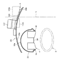
また、上記インパネ本体1の上面部7に設けられたインパネ隆起部22の最高部より運転席側に位置するインパネ凹部25のインパネ底部24には、図7に示すように、運転者の視線に対応するように後部上方を指向して膨出する膨出部32が形成され、この膨出部32に上記メータクラスタ部4が配設されている。このメータクラスタ部4は、上記膨出部32の上壁面を構成するメータフード部33と、後面視で上記ステアリングホイール3と重なる位置でこのステアリングホイール3の前方側に配設された計器盤面部34とを有している。この計器盤面部34には、左右に併設されたスピードメータ35とタコメータ36とが設けられることにより、上記画面表示部5に表示される情報と比べ、重要度の高い情報が表示されるように構成されている。   Further, the instrument panel bottom 24 of the instrument panel recess 25 located on the driver's seat side from the highest part of the instrument panel raised portion 22 provided on the upper surface portion 7 of the instrument panel body 1 has a driver's line of sight as shown in FIG. Correspondingly, a bulging portion 32 bulging toward the upper rear is formed, and the meter cluster portion 4 is disposed in the bulging portion 32. The meter cluster portion 4 includes a meter hood portion 33 constituting the upper wall surface of the bulging portion 32 and an instrument panel surface portion disposed on the front side of the steering wheel 3 at a position overlapping the steering wheel 3 in a rear view. 34. The instrument panel surface portion 34 is provided with a speedometer 35 and a tachometer 36 provided on the left and right sides, so that information with higher importance than the information displayed on the screen display portion 5 is displayed. It is configured.

そして、上記膨出部32の上壁面を構成するメータフード部33が、インパネ本体1に設けられた上記インパネ凹部25と、その後方に配設された後方傾斜面部8とに亘る範囲に配設されるとともに、上記計器盤面部34が、後方傾斜面部8上において上記膨出部32の後側に設置されることにより、運転席に着座した運転者が上記ステアリングホイール3の上半部に設けられた開口部を介して上記計器盤面部34のスピードメータ35およびタコメータ36を視認し得るように構成されている。   And the meter hood part 33 which comprises the upper wall surface of the said bulging part 32 is arrange | positioned in the range over the said instrument panel recessed part 25 provided in the instrument panel main body 1, and the back inclined surface part 8 arrange | positioned in the back. At the same time, the instrument panel surface portion 34 is installed on the rear inclined surface portion 8 on the rear side of the bulging portion 32 so that the driver seated in the driver's seat is provided in the upper half of the steering wheel 3. The speedometer 35 and the tachometer 36 of the instrument panel surface 34 can be visually recognized through the formed opening.

上記メータフード部33の前端部には、図23に示すように前突状の湾曲部33aが設けられて、この湾曲部33aが上記インパネ凹部25のインパネ底部24に連設されるとともに、上記メータクラスタ部4の左右両側方部を囲繞するように上記インパネ底部24が配設されている。また、上記メータクラスタ部4の最高部、つまりメータフード部33の車幅方向中央部33bは、図7に示すように、その前方側の上記インパネ隆起部22よりも上方に位置するように、その膨出高さが設定されている。   As shown in FIG. 23, a front projecting curved portion 33a is provided at the front end portion of the meter hood portion 33. The curved portion 33a is connected to the instrument panel bottom 24 of the instrument panel recess 25, and The instrument panel bottom 24 is disposed so as to surround the left and right sides of the meter cluster unit 4. Moreover, as shown in FIG. 7, the highest part of the meter cluster part 4, that is, the center part 33b in the vehicle width direction of the meter hood part 33, is positioned above the instrument panel raised part 22 on the front side. The bulge height is set.

上記インパネ本体1の車幅方向中央部から下方に垂下するように設置された上記センタコンソール部2は、図4および図8に示すように、その上端部が上記インパネ凹部25の後端に連続するとともに側面視で山形形状をなして車体の後方側へ膨出する山形部分37を構成し、この山形部分37の内部空間に各種の車載機器が配設されている。すなわち、上記センタコンソール部2の上方部15に、後部上方を指向しつつ後下がりに垂下する後壁面15aが形成され、この後壁面15aに沿うように上記ナビゲーション装置17からなる直方体形状の車載機器が設置されている。   As shown in FIGS. 4 and 8, the center console portion 2 installed so as to hang downward from the vehicle width direction central portion of the instrument panel main body 1 has an upper end continuous to the rear end of the instrument panel recess 25. In addition, a mountain-shaped portion 37 that forms a mountain shape in a side view and bulges toward the rear side of the vehicle body is formed, and various in-vehicle devices are disposed in the internal space of the mountain-shaped portion 37. That is, a rear wall surface 15a is formed in the upper portion 15 of the center console portion 2 so as to be directed downward at the rear and hang down downward, and the rectangular parallelepiped in-vehicle device including the navigation device 17 along the rear wall surface 15a. Is installed.

また、上記ナビゲーション装置17と、センタコンソール部2の山形部分37との間には、空調装置を構成するエアコンユニット39や、オーディオ装置用のスピーカ40等からなる他の車載機器が配設されている。上記エアコンユニット39は、上部に設けられたブロア(送風機)41と、下部に設けられたエバポレータ(クーラの蒸発器)42およびヒータ43と、上記吹出グリル16に連通するベンチダクト44とを有しており、車幅方向の中央部分に設けられている。   Further, between the navigation device 17 and the mountain-shaped portion 37 of the center console section 2, other in-vehicle devices including an air conditioner unit 39 constituting an air conditioner, a speaker 40 for an audio device, and the like are disposed. Yes. The air conditioner unit 39 includes a blower (blower) 41 provided in an upper portion, an evaporator (cooler evaporator) 42 and a heater 43 provided in a lower portion, and a bench duct 44 communicating with the blowout grill 16. It is provided at the center in the vehicle width direction.

そして、上記インパネ凹部25のうち反運転席側部位(右側部位)に配設された画面表示部5の直下方、つまり上記インパネ本体1の車幅方向中央部とセンタコンソール部2との交差部下方に位置するインストルメントパネルの内部空間に、上記エアコンユニット39が配設されている。また、上記山形部分37の前方側には、オーディオ装置用のスピーカ40が配設されるとともに、その後方側には、エアコンユニット39のベンチダクト44が配設され、かつこのベンチダクト44の下方に上記ナビゲーション装置17からなる直方体形状の車載機器が設置されている。   The instrument panel recess 25 is located directly below the screen display section 5 disposed on the side opposite to the driver's seat (right side section), that is, below the intersection between the center portion of the instrument panel body 1 in the vehicle width direction and the center console section 2. The air conditioner unit 39 is disposed in the internal space of the instrument panel located on the side. A speaker 40 for an audio device is disposed on the front side of the mountain-shaped portion 37, and a bench duct 44 of the air conditioner unit 39 is disposed on the rear side thereof, and below the bench duct 44. A rectangular parallelepiped vehicle-mounted device comprising the navigation device 17 is installed.

上記エアコンユニット39の主要部となるブロア41と、上記ナビゲーション装置17とは、車体の前後方向にオフセットして配設され、かつその設置高さが図4に示すように略同一に設定されるとともに、図9に示すように、上記ブロア41およびナビゲーション装置17がそれぞれインストルメントパネルの車幅方向中央部に配設されることにより、上記エアコンユニット39とナビゲーション装置17とが後面視で重複した部位に設置されるようになっている。   The blower 41, which is the main part of the air conditioner unit 39, and the navigation device 17 are arranged offset in the front-rear direction of the vehicle body, and their installation heights are set substantially the same as shown in FIG. At the same time, as shown in FIG. 9, the air blower 41 and the navigation device 17 are arranged at the center of the instrument panel in the vehicle width direction, so that the air conditioner unit 39 and the navigation device 17 overlap in the rear view. It is designed to be installed at the site.

上記のように車室前部に配設されて車体の後方側に膨出しつつ車幅方向に延在されたインパネ本体1と、車載機器に関連した情報を表示する画面表示部5とを有する自動車のインストルメントパネル装置において、上記インパネ本体1の車幅方向中央部に車載機器の操作部を有するセンタコンソール部2を接続することにより、車幅方向に連続しつつ緩やかに下方に傾斜するとともに平面視で車幅方向の中央部が最も後方に位置するように湾曲したインパネ後方傾斜面部を形成し、上記インパネ本体1の上面部7に、車幅方向の中央部から運転席側の端部に亘る部位を上方に隆起させたインパネ隆起部22を形成するとともに、その後端部から下方に延びる段差部23を形成し、この段差部23のうち上記センタコンソール部2の前方側に位置するとともに、平面視で運転席側(左側)を指向するように傾斜した部位(右側半部23b)に、上記画面表示部5を配設したため、車両の前方視界における見切り性が低下する等の問題を生じることなく、画面表示部5の視認性を効果的に確保できるとともに、インストルメントパネルの内部空間および上部空間を有効に利用できる等の利点がある。   As described above, it has an instrument panel body 1 which is disposed in the front part of the passenger compartment and extends in the vehicle width direction while expanding to the rear side of the vehicle body, and a screen display unit 5 which displays information related to the in-vehicle device. In the instrument panel device for an automobile, the center console portion 2 having the operation portion of the in-vehicle device is connected to the central portion of the instrument panel body 1 in the vehicle width direction, so that the vehicle panel is inclined downwardly while continuing in the vehicle width direction. An instrument panel rear inclined surface portion that is curved so that the center portion in the vehicle width direction is located at the rearmost position in plan view is formed on the upper surface portion 7 of the instrument panel main body 1 from the center portion in the vehicle width direction to the end on the driver's seat side. An instrument panel raised portion 22 is formed by raising a portion extending over the upper portion, and a step portion 23 extending downward from the rear end portion is formed. The step portion 23 is positioned on the front side of the center console portion 2. In addition, since the screen display unit 5 is disposed in a portion (right half 23b) that is inclined to face the driver's seat side (left side) in plan view, the parting ability in the front view of the vehicle is reduced. There is an advantage that the visibility of the screen display unit 5 can be effectively ensured without causing a problem, and the internal space and the upper space of the instrument panel can be effectively used.

すなわち、上記実施形態では、ナビゲーション装置17の操作スイッチおよびエアコンユニット39の操作部18を有するセンタコンソール部2がインパネ本体1の車幅方向中央部から車室の底部に向けて下方に垂下するように設置された自動車のインストルメントパネル装置において、上記センタコンソール部2の上方部15と、上記インパネ本体1の後方傾斜面部8,9とにより、車幅方向に連続しつつ、側面視で緩やかに下方に傾斜するとともに、平面視で車幅方向の中央部が最も後方に位置するように湾曲したインパネ後方傾斜面部を形成したため、運転席および助手席の居住性を損なうことなく、上記インストルメントパネルの内部空間および上部空間、特に車幅方向中央部分の内部空間および上部空間を充分に確保することができる。したがって、上記インストルメントパネルの内部空間の有効に利用して各種の車載機器を配設できるとともに、インストルメントパネルの上部空間を有効に利用して上記画面表示部5等を適正位置に配設できるという利点がある。   That is, in the above embodiment, the center console section 2 having the operation switch of the navigation device 17 and the operation section 18 of the air conditioner unit 39 hangs downward from the center in the vehicle width direction of the instrument panel body 1 toward the bottom of the passenger compartment. In the instrument panel device for a vehicle installed in the vehicle, the upper portion 15 of the center console portion 2 and the rear inclined surface portions 8 and 9 of the instrument panel main body 1 are continuous in the vehicle width direction and gently in side view. Since the instrument panel rear inclined surface portion that is inclined downward and curved so that the center portion in the vehicle width direction is located at the rearmost in plan view, the instrument panel can be used without impairing the comfortability of the driver's seat and the passenger seat. The internal space and upper space of the vehicle, especially the inner space and upper space in the center in the vehicle width direction, can be secured sufficiently. That. Therefore, various in-vehicle devices can be disposed by effectively using the internal space of the instrument panel, and the screen display unit 5 and the like can be disposed at appropriate positions by effectively utilizing the upper space of the instrument panel. There is an advantage.

そして、上記インパネ本体1の上面部7にインパネ隆起部22を形成するとともに、その後端部に設けられた段差部23の反運転席側部位(車幅方向中央部側部位)である右側半部23bを運転席側に向けて傾斜させるとともに、この部位に上記画面表示部5を配設したため、上記画面表示部5の視認性を確保し得るようにその上下寸法を、ある程度大きく設定した場合でも、その存在により運転席前方の視界が遮られてその見切り性が低下したり、運転者が圧迫感を受けたりするのを防止しつつ、上記画面表示部5に設けられた各表示部28〜31の表示情報を、ステアリングホイール3により遮られることなく適正に視認できるという利点がある。   And the instrument panel bulge 22 is formed on the upper surface 7 of the instrument panel body 1, and the right half is the counter-driver seat side part (vehicle width direction central part side part) of the step part 23 provided at the rear end part. 23b is inclined toward the driver's seat side, and the screen display unit 5 is disposed at this portion. Therefore, even when the vertical dimension is set to be large to some extent so that the visibility of the screen display unit 5 can be secured. The presence of the visual field in front of the driver's seat is obstructed and the parting ability is reduced, and the driver is not compressed. The display units 28 to 28 provided on the screen display unit 5 are prevented. There is an advantage that the display information 31 can be properly visually recognized without being blocked by the steering wheel 3.

特に、上記実施形態に示すように、画面表示部5が設けられた上記段差部23の後方側に位置するインパネ底部24を、運転者の視線方向に対応させて後上がりに傾斜させた場合には、上記画面表示部5の底部をできるだけ下方に位置させて、その上端位置が高くなるのを抑制しつつ、その視認性を効果的に確保することができる。したがって、上記画面表示部5が車室前部に配設されること起因して、車両の前方視界における見切り性が低下したり、運転者が圧迫感を受けたりすること等を、より効果的に防止しつつ、上記画面表示部5において表示された情報を運転者が適正に把握することが可能である。   In particular, as shown in the above embodiment, when the instrument panel bottom 24 located on the rear side of the stepped portion 23 provided with the screen display unit 5 is tilted rearward corresponding to the driver's line of sight. The position of the bottom of the screen display unit 5 is positioned as low as possible, and the visibility can be effectively ensured while suppressing the upper end position from becoming higher. Therefore, it is more effective that the screen display unit 5 is disposed in the front part of the passenger compartment, so that the parting ability in the front field of view of the vehicle is reduced and the driver feels pressure. It is possible for the driver to properly grasp the information displayed on the screen display unit 5 while preventing it.

また、上記実施形態に示すように、インパネ隆起部22の後端部に設けられた段差部23をインパネ本体1の車幅方向中央部から運転席側端部に亘るように延設するとともに、上記段差部23とインパネ後方傾斜面部との間にインパネ底部24を形成し、このインパネ底部24上でステアリングホイール3の前方位置にメータクラスタ部4の計器盤面部34を配設することにより、図5に示すように、この計器盤面部34と、上記画面表示部5とを平面視で左右にオフセットさせて配設した構成によれば、このメータクラスタ部4と画面表示部5とを後面視で上下に連続させて配設した場合のように、これらのうちの一方を車体の上方側に位置させることによりその視認性を確保する等の構成をとる必要がなく、上記メータクラスタ部4および画面表示部5の上端位置が高くなるのを防止することができる。   Further, as shown in the above embodiment, the stepped portion 23 provided at the rear end portion of the instrument panel raised portion 22 extends from the vehicle width direction center portion of the instrument panel body 1 to the driver seat side end portion, and An instrument panel bottom portion 24 is formed between the step portion 23 and the instrument panel rear inclined surface portion, and an instrument panel surface portion 34 of the meter cluster portion 4 is disposed on the instrument panel bottom portion 24 at a position in front of the steering wheel 3. As shown in FIG. 5, according to the configuration in which the instrument panel surface portion 34 and the screen display portion 5 are arranged to be offset left and right in a plan view, the meter cluster portion 4 and the screen display portion 5 are viewed from the rear. Therefore, it is not necessary to take a configuration such as ensuring the visibility by positioning one of these on the upper side of the vehicle body, as in the case where the meter cluster unit 4 Yo It is possible to prevent the upper end position of the screen display unit 5 is increased.

したがって、上記メータクラスタ部4および画面表示部5の視認性を確保し得るようにその大きさを設定した場合においても、これらの存在により車両の前方視界が遮られてその見切り性が低下したり、運転者が圧迫感を受けたりすることがなく、運転席に着座してステアリングホイール3を把持した運転者が、ステアリングホイール3の開口部等を介して上記メータクラスタ部4の計器盤面部34に設けられたスピードメータ35およびタコメータ36を適正に視認できるとともに、ステアリングホイール3越しに上記画面表示部5の表示情報を適正に視認できるという利点がある。   Therefore, even when the size is set so that the visibility of the meter cluster unit 4 and the screen display unit 5 can be ensured, the presence of these blocks the front view of the vehicle, thereby reducing the parting ability. The driver who is seated in the driver's seat and grips the steering wheel 3 without receiving a feeling of pressure, the instrument panel surface portion 34 of the meter cluster unit 4 through the opening of the steering wheel 3 or the like. There are advantages that the speedometer 35 and the tachometer 36 provided in can be properly visually recognized and the display information of the screen display unit 5 can be appropriately visually recognized through the steering wheel 3.

なお、人間の網膜位置による情報受容特性(視野)は、網膜の中心窩から離れるにしたがって低下する傾向があり、図10に示すように、視力、色弁別等の視機能が優れ、高精度の情報受容が可能な弁別視野S1と、眼球運動だけで情報を注視し、瞬時に特定情報を雑音内より受容できる有効視野S2と、頭部運動が眼球運動を助ける状態で発生し、無理なく注視が可能な注視安定視野S3と、呈示された情報の存在を判定できる程度の識別力しかないが、人間の空間座標感覚に影響を与える誘導視野S4と、情報受容は極度に低下し、強い刺激等に注視動作を誘発させる程度の補助的な働きをする誘導視野S5とを有し、上記各視野S1〜S5が弁別視野S1を中心とした波紋状に配設されている。そして、上記情報受容特性は、その上下方向に比べて左右方向が広くなる傾向があるため、上記のようにメータクラスタ部4と画面表示部5とを左右にオフセットさせて配設すれば、これらを後面視で上下に連続させて配設した場合に比べ、上記メータクラスタ部4および画面表示部5に表示された情報を容易かつ正確に識別できるという利点がある。   The information acceptance characteristic (field of view) depending on the human retina position tends to decrease as the distance from the central fovea of the retina increases. As shown in FIG. 10, visual functions such as visual acuity and color discrimination are excellent, and high accuracy. Discrimination visual field S1 capable of accepting information, effective visual field S2 that can instantly receive specific information from within the noise, and head movement that occurs in a state that aids eye movement, and gazes effortlessly Gaze stable visual field S3 and discriminating power that can determine the presence of the presented information, but the guidance visual field S4 that affects human spatial coordinate sensation, and the information acceptance is extremely reduced and strong stimulation The visual field S5 has a guiding visual field S5 that has an auxiliary function of inducing a gaze operation, and the visual fields S1 to S5 are arranged in a ripple shape centered on the discrimination visual field S1. Since the information acceptance characteristics tend to be wider in the horizontal direction than in the vertical direction, if the meter cluster unit 4 and the screen display unit 5 are offset to the left and right as described above, There is an advantage that information displayed on the meter cluster unit 4 and the screen display unit 5 can be easily and accurately identified as compared with the case where these are arranged continuously in the vertical direction in the rear view.

特に、上記実施形態に示すように、運転席の前方側に位置するメータクラスタ部4に、スピードメータ35およびタコメータ36を配設して現在の走行速度およびエンジン回転数からなる重要度が高い情報を表示するとともに、上記メータクラスタ部4に対して車幅方向にオフセットした位置に配設された上記画面表示部5に、DIS(ドライバーインフォメーションシステム)から提供される平均速度および平均燃費や外気温度等の比較的に重要度が低い情報を表示するように構成した場合には、運転席の前方に位置するフロントウインドを介して車両の前方部を視認しつつ運転している運転者が、その眼球を大きく移動させることなく、上記メータクラスタ部4に表示された重要な情報を迅速かつ容易に視認できるという利点がある。   In particular, as shown in the above embodiment, the speedometer 35 and the tachometer 36 are disposed in the meter cluster unit 4 located on the front side of the driver's seat, and the highly important information including the current traveling speed and the engine speed is high. Is displayed on the screen display unit 5 disposed at a position offset in the vehicle width direction with respect to the meter cluster unit 4, and the average speed, average fuel consumption, and outside air temperature provided from DIS (Driver Information System) are displayed. If it is configured to display information of relatively low importance, such as a driver who is driving while visually checking the front part of the vehicle via the front window located in front of the driver's seat, There is an advantage that important information displayed on the meter cluster unit 4 can be visually recognized quickly and easily without greatly moving the eyeball.

また、上記実施形態では、インパネ底部24に連設されて上方に膨出するよう設置されたメータフード部33と、このメータフード部33の下方に配設されて運転席側を指向する計器盤面部34とをメータクラスタ部4に設け、上記メータフード部33の前端部に設けられた前突状の湾曲部33aを上記インパネ底部24に連設するとともに、上記メータクラスタ部4の左右両側方部を囲繞するように上記インパネ底部24を配設したため、図5に示すように、平面視で半円形状に形成されたメータクラスタ部4が、運転席の前方部に配設されたインパネ底部24上に膨出して設置されることにより、運転席が飛行機のコックピット状に構成されてスポーティな操縦感覚が得られるという利点がある。   Moreover, in the said embodiment, the meter hood part 33 connected to the instrument panel bottom 24 and installed so as to bulge upward, and the instrument panel surface disposed below the meter hood part 33 and directed toward the driver's seat 34 is provided in the meter cluster portion 4, and a front-projecting curved portion 33 a provided at the front end portion of the meter hood portion 33 is connected to the instrument panel bottom 24, and both the left and right sides of the meter cluster portion 4 are provided. Since the instrument panel bottom 24 is disposed so as to surround the instrument panel, as shown in FIG. 5, the instrument cluster bottom 4 is formed in a semicircular shape in a plan view and is disposed in the front part of the driver's seat. By being bulged and installed on the vehicle 24, there is an advantage that the driver's seat is configured in the shape of a cockpit of an airplane and a sporty control feeling can be obtained.

さらに、図7に示すように、上記メータフード部33の車幅方向中央部33bからなるメータクラスタ部4の最高部を、その前方側に位置する上記インパネ隆起部22よりも上方に位置させるように構成した場合には、このインパネ隆起部22を上記メータクラスタ部4により隠蔽することができる。したがって、上記インパネ隆起部22をメータクラスタ部4の上方に位置させた場合のように、車両の前方視界における見切り性が低下したり、運転者が圧迫感を受けたりすることを、より効果的に防止しつつ、上記メータクラスタ部4において表示された情報を運転者が適正に把握できるように、上記メータクラスタ部4の上下寸法を充分に確保できる等の利点がある。   Further, as shown in FIG. 7, the highest part of the meter cluster part 4 formed of the center part 33 b in the vehicle width direction of the meter hood part 33 is positioned above the instrument panel raised part 22 located on the front side. In this case, the instrument panel raised portion 22 can be hidden by the meter cluster portion 4. Therefore, as in the case where the instrument panel raised portion 22 is positioned above the meter cluster portion 4, it is more effective that the parting ability in the front view of the vehicle is reduced or the driver receives a feeling of pressure. There is an advantage that the vertical dimension of the meter cluster unit 4 can be sufficiently secured so that the driver can properly grasp the information displayed in the meter cluster unit 4 while preventing the above problem.

また、上記実施形態では、後面視でメータクラスタ部4と重複する部位で、その前方側に位置する上記インパネ凹部25の段差部23、つまりインパネ本体1の上面部7における車幅方向中央部から運転席側の端部に亘る部分に設けられた上記段差部23の左側半部(運転席側半部)23aに、SDカードのスロット部26、携帯用オーディオ機器のコネクタ27または収納部等からなる車載機能部を配設したため、上記メータクラスタ部4により隠蔽されて運転状態の運転者からは見えないが、助手席側からは視認可能な位置に配設された上記段差部23の左側半部23aを有効に利用することが可能であり、インパネ本体1の上面部7における利用効率を向上させることができる。   Moreover, in the said embodiment, it is the site | part which overlaps with the meter cluster part 4 by the rear view, from the level | step-difference part 23 of the said instrument panel recessed part 25 located in the front side, ie, the vehicle width direction center part in the upper surface part 7 of the instrument panel main body 1. From the left half (driver's seat side half) 23a of the step 23 provided at the end portion on the driver's seat side, from the slot portion 26 of the SD card, the connector 27 or the storage portion of the portable audio device, etc. Since the in-vehicle functional unit is arranged, it is hidden by the meter cluster unit 4 and cannot be seen by the driver in the driving state, but the left half of the stepped portion 23 arranged at a position visible from the passenger seat side. The part 23a can be used effectively, and the utilization efficiency in the upper surface part 7 of the instrument panel body 1 can be improved.

さらに、上記のように画面表示部5の直下方位置にエアコンユニット39を収容し、側面視でエアコンユニット39の直後方に位置するとともに、後面視でエアコンユニット39と重複した部位に、上記ナビゲーション装置17等からなる車載機器を配設した場合には、上記インストルメントパネルの下方部に形成された容量の大きな内部空間を有効に利用して、上記エアコンユニット39とナビゲーション装置17等からなる車載機器とを適正に配設することが可能である。   Further, as described above, the air conditioner unit 39 is accommodated at a position directly below the screen display unit 5 and is located immediately after the air conditioner unit 39 in a side view, and the navigation unit is located at a portion overlapping the air conditioner unit 39 in a rear view. When an in-vehicle device composed of the device 17 or the like is provided, an in-vehicle device composed of the air conditioner unit 39, the navigation device 17 or the like is effectively used by effectively utilizing a large internal space formed in the lower portion of the instrument panel. It is possible to arrange the devices properly.

すなわち、上記実施形態では、インパネ本体1の車幅方向中央部から下方に垂下するようにセンタコンソール部2が設置された自動車のインストルメントパネル装置において、上記センタコンソール部2の上端部を上記インパネ凹部25の後端に連続させることにより、側面視で山形形状をなして車体の後方側へ膨出する山形部分37を構成し、この山形部分37の下方に上記ナビゲーション装置17からなる直方体形状の車載機器を配設するとともに、このナビゲーション装置17と、山形部分37との間の前方側にオーディオ装置用のスピーカ40を配設し、かつその後方側にエアコンユニット39のベンチダクト44を配設する等により、上記山形部分37の内部空間を有効に利用して各種の車載機器を効率よく配設できるという利点がある。   That is, in the above-described embodiment, in the instrument panel device for an automobile in which the center console portion 2 is installed so as to hang downward from the vehicle width direction center portion of the instrument panel body 1, the upper end portion of the center console portion 2 is connected to the instrument panel. By continuing to the rear end of the concave portion 25, a mountain-shaped portion 37 that forms a mountain shape in a side view and bulges toward the rear side of the vehicle body is formed, and a rectangular parallelepiped shape comprising the navigation device 17 is formed below the mountain-shaped portion 37. In addition to the on-vehicle equipment, the speaker 40 for the audio device is disposed on the front side between the navigation device 17 and the mountain-shaped portion 37, and the bench duct 44 of the air conditioner unit 39 is disposed on the rear side. The advantage that various in-vehicle devices can be efficiently arranged by effectively using the internal space of the mountain-shaped portion 37. A.

また、上記実施形態に示すように、インパネ本体1とセンタコンソール部2との交差部に位置するインストルメントパネルの内部空間、つまりインストルメントパネルの車幅方向中央に形成された内部空間に上記エアコンユニット39を配設した場合には、欧米用の左ハンドル車と日本国内用の右ハンドル車とで、上記エアコンユニット39を左右逆転させて配設する等の構造をとる必要がないため、インストルメントパネル装置の汎用性を効果的に向上できるという利点がある。   In addition, as shown in the above-described embodiment, the air conditioner is provided in the internal space of the instrument panel located at the intersection of the instrument panel body 1 and the center console portion 2, that is, the internal space formed in the center of the instrument panel in the vehicle width direction. When the unit 39 is provided, it is not necessary to adopt a structure in which the air-conditioner unit 39 is reversed left and right between a left-hand drive car for Europe and the United States and a right-hand drive car for use in Japan. There is an advantage that the versatility of the instrument panel device can be effectively improved.

さらに、上記実施形態では、画面表示部5が配設されたインパネ凹部25の後端部右側にセンタコンソール部2の上方部15を接続し、このインパネ凹部25に設けられた段差部23と、上記センタコンソール部2とによりインパネ本体1の運転席側部位から車幅方向の中央部に沿って連続した鎌形状の意匠面を形成したため、図11示すように、上記フロントウインドを介して車両の前方部Xを視認しつつ運転している運転者が、その側方から下方に向けて流れるように視線を移動させることにより(矢印Y参照)、上記画面表示部5に表示された車載機器に関する情報と、上記センタコンソール部2の上方部15に設けられたナビゲーション装置17に表示された画像等とを、順次視認できるという利点がある。   Furthermore, in the said embodiment, the upper part 15 of the center console part 2 is connected to the rear-end part right side of the instrument panel recessed part 25 by which the screen display part 5 was arrange | positioned, The level | step-difference part 23 provided in this instrument panel recessed part 25, Since the center console portion 2 forms a sickle-shaped design surface continuous from the driver seat side portion of the instrument panel body 1 along the center portion in the vehicle width direction, as shown in FIG. The driver who is driving while visually recognizing the front portion X moves the line of sight so as to flow downward from the side (see arrow Y), and thus relates to the in-vehicle device displayed on the screen display unit 5. There is an advantage that information and images displayed on the navigation device 17 provided in the upper portion 15 of the center console portion 2 can be sequentially viewed.

また、運転席の側方に配設されたシフトレバー45の上方に、上記ナビゲーション装置17およびエアコンユニット39の操作部18を配設することにより、運転時に運転者により把持された状態にあるステアリングホイール3と、必要に応じて運転者により操作される上記シフトレバー45との間に、上記ナビゲーション装置17および操作部18を位置させるように構成したため、これらを運転者が容易かつ適正に操作できるという利点もある。   Further, by providing the navigation device 17 and the operation unit 18 of the air conditioner unit 39 above the shift lever 45 disposed on the side of the driver's seat, the steering wheel that is gripped by the driver during driving is provided. Since the navigation device 17 and the operation unit 18 are positioned between the wheel 3 and the shift lever 45 operated by the driver as necessary, the driver can easily and appropriately operate them. There is also an advantage.

また、上記実施形態に示すように、インパネ凹部25の段差部23に、その周囲のインパネ表面部と異なる意匠を施した場合には、この段差部23に設けられた上記画面表示部5、スロット部26およびコネクタ27を利用する際の利便性を向上させることができるとともに、車室内におけるデザイン効果を際立たせて運転者の受けるスポーティ感を、より効果的に向上させることができる。   Further, as shown in the above embodiment, when the step portion 23 of the instrument panel recess 25 is provided with a design different from the peripheral instrument panel surface portion, the screen display portion 5 provided in the step portion 23 and the slot Convenience when using the part 26 and the connector 27 can be improved, and the sporty feeling received by the driver can be improved more effectively by making the design effect in the passenger compartment stand out.

例えば、上記インパネ本体1の表面部が暗灰色のシボ状に形成されている場合において、車載機能部の手前側に位置する段差部23の左側半部23aに黒色のパネルを貼着するとともに、その右側に連続する段差部23の右側半部23bにダークガラスを取り付けることにより、上記段差部23を、光沢のある表面としてあたかも消灯した表示画面に見えるように構成した場合には、上記インパネ本体1の上面部7に設けられた所定長さの段差部23に、車載機能部および画面表示部5をそれぞれ設けたにも拘わらず、あたかもこの段差部23の全体が画面表示部5であるかのような視覚的効果を与えることにより、デザイン性を効果的に向上させることができる。   For example, in the case where the surface portion of the instrument panel body 1 is formed in a dark gray embossed shape, a black panel is attached to the left half portion 23a of the stepped portion 23 located on the near side of the in-vehicle function unit, When the stepped portion 23 is configured to appear as a display screen turned off as a glossy surface by attaching dark glass to the right half portion 23b of the stepped portion 23 continuous on the right side, the instrument panel body Whether the stepped portion 23 as a whole is the screen display portion 5 even though the in-vehicle function portion and the screen display portion 5 are respectively provided in the stepped portion 23 of a predetermined length provided on the upper surface portion 7 of FIG. By giving such a visual effect, the design can be effectively improved.

次に、本発明に係るインストルメントパネル装置の第2の実施形態について、図12〜図19を参照しつつ説明する。なお、上記第1の実施形態と同様の構成要素については同符号を付すとともに、その詳細な説明は省略する。   Next, a second embodiment of the instrument panel device according to the present invention will be described with reference to FIGS. The same components as those in the first embodiment are denoted by the same reference numerals, and detailed description thereof is omitted.

この第2の実施形態では、図12および図17に示すように、上記画面表示部5に、上記エアコンユニット39およびオーディオ装置等からなる車載機器に関連した情報を表示する液晶表示部105に加えて、ナビゲーション装置117が設けられている。比較的装置本体の容積が大きい上記ナビゲーション装置117は、上記段差部23の右側半部23bのうち運転席側の部分に配置されており、比較的装置本体の容積が小さい上記液晶表示部105は上記段差部23の右側半部23bのうち助手席側の部分に車幅方向に延びるように配置されている。上記センタコンソール部2には、上記吹出グリル16の直下方に、エアコンユニット39およびオーディオ装置等の操作スイッチからなる操作部118が設けられている。   In the second embodiment, as shown in FIG. 12 and FIG. 17, in addition to the liquid crystal display unit 105 that displays information related to the in-vehicle device including the air conditioner unit 39 and the audio device on the screen display unit 5. A navigation device 117 is provided. The navigation device 117 having a relatively large volume of the apparatus main body is disposed in a portion on the driver's seat side of the right half 23b of the stepped portion 23, and the liquid crystal display section 105 having a relatively small volume of the apparatus main body is It arrange | positions so that it may extend in the vehicle width direction in the part by the side of a passenger seat among the right side half parts 23b of the said level | step-difference part 23. FIG. The center console section 2 is provided with an operation section 118 including operation switches such as an air conditioner unit 39 and an audio device immediately below the blow grill 16.

上記インストルメントパネル装置のインパネ本体1には、上記ディフロスター用の吹出口19に加え、サイドミラーの視認性向上のために設けられたサイドガラスのくもりを除去するための一対のデミスター用の吹出口150,151が形成されている。これらデミスター用の吹出口150,151は、インパネ本体1に設けられた上記後方傾斜面部8,9の車幅方向外側方部のうち上記ベント口20,21のそれぞれ上方に設けられており、空調用エアを車室内の側方部に吹き出す。   In the instrument panel body 1 of the instrument panel device, a pair of demister air outlets for removing the cloudy side glass provided for improving the visibility of the side mirror in addition to the air outlet 19 for the defroster. 150 and 151 are formed. The demister outlets 150 and 151 are provided above the vent ports 20 and 21 in the vehicle width direction outer side portions of the rear inclined surface portions 8 and 9 provided in the instrument panel body 1, respectively. Air is blown out to the side of the passenger compartment.

上記インパネ本体1には、図12に示すように、空調用エアを上記ディフロスター用の吹出口19および上記デミスター用の吹出口150,151に導くためのデフダクト170が上記ベンチダクト44の前方に形成されている。このデフダクト170は、図13に示すように、インパネ本体1の前側部分において車幅方向に延びている。このデフダクト170は、図14および図18に示すように、上方に隆起した上記インパネ隆起部22の下方を通っており、その容積が十分に確保されている。   As shown in FIG. 12, the instrument panel body 1 has a differential duct 170 for guiding air-conditioning air to the defroster air outlet 19 and the demister air outlets 150 and 151 in front of the bench duct 44. Is formed. As shown in FIG. 13, the differential duct 170 extends in the vehicle width direction at the front portion of the instrument panel body 1. As shown in FIGS. 14 and 18, the differential duct 170 passes below the instrument panel raised portion 22 raised upward, and a sufficient volume is secured.

上記デフダクト170の底部には、車幅方向の中央部分において上下に貫通する左右一対のデフ開口172a,172bが形成されている。上記車幅方向の中央部分に配置されたエアコンユニット39は、このデフダクト170の下方に配設されており、エアコンユニット39から排出された空調用エアはこれらデフ開口172a,172bからデフダクト170に導入された後、上記ディフロスター用の吹出口19および上記デミスター用の吹出口150,151に導かれる。   A pair of left and right differential openings 172a and 172b penetrating vertically at the center portion in the vehicle width direction are formed at the bottom of the differential duct 170. The air conditioner unit 39 disposed in the center portion in the vehicle width direction is disposed below the differential duct 170, and the air conditioning air discharged from the air conditioner unit 39 is introduced into the differential duct 170 through the differential openings 172a and 172b. Then, the air is guided to the defroster outlet 19 and the demister outlets 150 and 151.

上記デフ開口172a,172bは、上記センタコンソール部2の前方側であって上記段差部23の右側半部23bの下方に形成されている。より詳細には、図16に示すように、運転席側のデフ開口172aは、この段差部23の右側半部23bの運転席側の部分に設けられた上記ナビゲーション装置117の下方に設けられている。一方、助手席側のデフ開口172bは、上記段差部23の右側半部23bの助手席側の部分に設けられた上記液晶表示部105の下方に設けられている。ここで、この液晶表示部105は上述のように車両前後方向の厚さが薄く、上記助手席側のデフ開口172bの前端は上記液晶表示部105の前端よりも前側に位置しており、この助手席側のデフ開口172bの一部は平面視で液晶表示部105と非重複状態となっている。このように上記液晶表示部105と非重複状態であれば、この非重複部分において上記デフダクト170の高さを大きく設定することができる。そこで、本装置では、図15に示すように、この非重複部分においてデフダクト170の高さを十分に確保することで、空調用エアが上記デフ開口172bを通過する際の抵抗を抑制している。   The differential openings 172a and 172b are formed in front of the center console portion 2 and below the right half portion 23b of the stepped portion 23. More specifically, as shown in FIG. 16, the driver seat side differential opening 172 a is provided below the navigation device 117 provided in the driver seat side portion of the right half portion 23 b of the stepped portion 23. Yes. On the other hand, the diff opening 172b on the passenger seat side is provided below the liquid crystal display unit 105 provided on the passenger seat side portion of the right half portion 23b of the stepped portion 23. Here, the liquid crystal display unit 105 is thin in the vehicle front-rear direction as described above, and the front end of the passenger seat side differential opening 172b is located in front of the front end of the liquid crystal display unit 105. A part of the passenger seat side differential opening 172b is not overlapped with the liquid crystal display unit 105 in a plan view. In this way, if the liquid crystal display unit 105 is in a non-overlapping state, the height of the differential duct 170 can be set large in this non-overlapping part. Therefore, in this apparatus, as shown in FIG. 15, the resistance when the air-conditioning air passes through the differential opening 172b is suppressed by sufficiently securing the height of the differential duct 170 in this non-overlapping portion. .

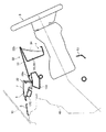
上記インパネ本体1には、図13および図19に示すように、上記エアコンユニット39と上記吹出グリル16とを連通する上記ベンチダクト44に連通して、空調用エアを上記ベント口20,21に導くためのベント口用ベンチダクト144が形成されている。   As shown in FIGS. 13 and 19, the instrument panel body 1 communicates with the bench duct 44, which communicates the air conditioner unit 39 and the blowing grill 16, and air conditioning air is supplied to the vent ports 20, 21. A vent duct 144 for guiding is formed.

上記ベンチダクト44の底部には、上記デフ開口172a,172bのそれぞれ後方であって上記センタコンソール部2の下方において上下に貫通する左右一対のベント開口146a,146bが形成されている。上記ベンチダクト44の下方に配設された上記エアコンユニット39から排出された空調用エアは、これらベント開口146a,146bを通って上記ベンチダクト44に導入され、上記吹出グリル16に導かれる。また、上記空調用エアは、このベンチダクト44から上記ベント口用ベンチダクト144を通って上記ベント口20,21に導かれる。   A pair of left and right vent openings 146a and 146b are formed at the bottom of the bench duct 44 so as to penetrate the upper and lower sides behind the differential openings 172a and 172b and below the center console section 2, respectively. Air-conditioning air discharged from the air-conditioning unit 39 disposed below the bench duct 44 is introduced into the bench duct 44 through the vent openings 146a and 146b and guided to the blow-out grill 16. The air for air conditioning is led from the bench duct 44 to the vent ports 20 and 21 through the vent port bench duct 144.

上記ベント口用ベンチダクト144は、上記ベンチダクト44のうち上記ベント開口146a,146b近傍部分から左右に延びている。ベント口用ベンチダクト144のうち運転席側のベント口用ベンチダクト144は、運転席側のベント開口146a近傍部分から前方に延び、上記メータクラスタ部4の前方に配設されている上記段差部23の下方を通りつつ運転席側の上記ベント口20に延びており、メータフード部33の湾曲部33aに沿って湾曲する形状を有している。ここで、上記段差部23の前方には上方に隆起したインパネ隆起部22が形成されており、このインパネ隆起部22および段差部23の下方には十分な大きさの空間が確保されている。そして、上記ナビゲーション装置117および液晶表示部105は上記段差部23の前方に配置されている。そのため、上記ベント口用ベンチダクト144は、図18に示すように、上記段差部23の下方において、これらナビゲーション装置117および液晶表示部105と干渉することなく十分な容積が確保された状態で配設されている。また、このベント口用ベンチダクト144は上記メータクラスタ部4の前方において、このメータクラスタ部4と干渉することなく配設されている。   The vent opening bench duct 144 extends from the bench duct 44 to the left and right from the vicinity of the vent openings 146a and 146b. The vent opening bench duct 144 on the driver seat side of the vent opening bench duct 144 extends forward from the vicinity of the vent opening 146a on the driver seat side, and is provided in front of the meter cluster section 4. 23, extending to the vent opening 20 on the driver's seat side while passing below 23, and has a shape that curves along the curved portion 33 a of the meter hood portion 33. Here, an instrument panel raised portion 22 that is raised upward is formed in front of the step portion 23, and a sufficiently large space is secured below the instrument panel raised portion 22 and the step portion 23. The navigation device 117 and the liquid crystal display unit 105 are disposed in front of the stepped portion 23. Therefore, as shown in FIG. 18, the vent opening bench duct 144 is arranged below the step portion 23 in a state where a sufficient volume is ensured without interfering with the navigation device 117 and the liquid crystal display unit 105. It is installed. The vent opening bench duct 144 is disposed in front of the meter cluster unit 4 without interfering with the meter cluster unit 4.

上記のようにこのインパネ本体1では、上記インパネ本体1の上面部7の前側部分にデフロスター用の吹出口19を形成し、上記画面表示部5の直下方位置にエアコンユニット39を収容し、上記インパネ本体1に、上下に貫通し上記エアコンユニット39から上記デフロスター用の吹出口19に空調用エアを導くためのデフ開口172a,172bを、これらデフ開口172a,172bのうち運転席側のデフ開口172bの一部が平面視で上記画面表示部5と重複しないように形成したため、このデフ開口172bを通過する空調用エアが上記画面表示部5の液晶表示部105と干渉するのを抑制することができ、空調用エアの流れをスムーズにすることができるという利点がある。   As described above, in the instrument panel body 1, the defroster air outlet 19 is formed in the front portion of the upper surface portion 7 of the instrument panel body 1, and the air conditioner unit 39 is accommodated at a position directly below the screen display unit 5. Differential openings 172a and 172b that penetrate vertically through the instrument panel main body 1 and lead the air for air conditioning from the air conditioner unit 39 to the blowout opening 19 for the defroster, and the differential openings on the driver seat side among these differential openings 172a and 172b. Since part of 172b is formed so as not to overlap with the screen display unit 5 in plan view, the air conditioning air passing through the differential opening 172b is prevented from interfering with the liquid crystal display unit 105 of the screen display unit 5. There is an advantage that the flow of air for air conditioning can be made smooth.

すなわち、前後方向の厚さの薄い上記液晶表示部105の下方にデフ開口172bを形成して、この液晶表示部105とデフ開口172bとを平面視で非重複状態とすることで、上記エアコンユニット39から上記デフロスター用の吹出口19に空調用エアを導くためのデフダクト170のデフ開口172b付近の高さを十分に確保することができ、空調用エアが上記デフ開口172bを通過する際の抵抗を抑制することができる。   That is, a differential opening 172b is formed below the liquid crystal display unit 105 having a small thickness in the front-rear direction, and the liquid crystal display unit 105 and the differential opening 172b are in a non-overlapping state in plan view, thereby 39, a sufficient height in the vicinity of the differential opening 172b of the differential duct 170 for guiding the air for air conditioning from the air outlet 19 for the defroster can be secured, and resistance when the air for air conditioning passes through the differential opening 172b. Can be suppressed.

また、上記インパネ本体1の車幅方向外側方部に、空調用エアを車室内の側方部に吹き出すためのベント口20を形成し、上記エアコンユニット39から上記ベント口20に空調用エアを導くためのベント口用ベンチダクト144を、上記メータクラスタ部4の前方、かつ、上記段差部23の下方を通って車幅方向に延びるよう配設したため、上方に隆起したインパネ隆起部22の下方すなわち上記段差部23の下方に確保された所定の容量の空間を利用して、上記メータクラスタ部4および上記段差部23の前方に配設される画面表示部5との干渉を回避しつつ、ベント口用ベンチダクト144を、その容積を十分に確保した状態で配設することができるという利点がある。   Further, a vent port 20 for blowing air-conditioning air to the side portion in the vehicle compartment is formed in the vehicle width direction outer side portion of the instrument panel body 1, and air-conditioning air is supplied from the air-conditioning unit 39 to the vent port 20. The vent vent bench duct 144 for guiding is arranged to extend in the vehicle width direction in front of the meter cluster portion 4 and below the stepped portion 23, so that the bottom of the instrument panel raised portion 22 raised upward is provided. That is, while utilizing a space of a predetermined capacity secured below the step portion 23, while avoiding interference with the meter cluster portion 4 and the screen display portion 5 disposed in front of the step portion 23, There is an advantage that the vent duct 144 for the vent opening can be disposed in a state where the volume is sufficiently secured.

ここで、上記デフ開口172a,172bの配置は上記に限らない。例えば、助手席側のデフ開口172bに加えて運転席側のデフ開口172aを上記画面表示部5と平面視で重複しないように配設してもよい。また、デフ開口の数も上記に限らず、1つのデフ開口のみを設け、その一部が上記画面表示部5と重複しないように配設してもよい。   Here, the arrangement of the differential openings 172a and 172b is not limited to the above. For example, in addition to the passenger seat side differential opening 172b, the driver seat side differential opening 172a may be arranged so as not to overlap the screen display unit 5 in plan view. Further, the number of differential openings is not limited to the above, and only one differential opening may be provided and a part thereof may be disposed so as not to overlap with the screen display unit 5.

また、上記画面表示部5の具体的構成は前記に限らない。例えば、上記ナビゲーション装置117を助手席側に配置し上記液晶表示部105を運転席側に配置してもよい。ただし、運転者が見る機会の高いナビゲーション装置117を運転席側に配置すれば、運転者の眼球の動きを小さく抑えてより快適な運転を実現することができる。また、センターコンソール部2にナビゲーション装置の本体を設けておき、画面表示部5には簡易版のナビゲーション装置を設けるようにしてもよい。   The specific configuration of the screen display unit 5 is not limited to the above. For example, the navigation device 117 may be disposed on the passenger seat side, and the liquid crystal display unit 105 may be disposed on the driver seat side. However, if the navigation device 117 having a high chance of being seen by the driver is arranged on the driver's seat side, the driver's eyeball movement can be kept small, and more comfortable driving can be realized. In addition, a navigation device main body may be provided in the center console unit 2, and a simplified navigation device may be provided in the screen display unit 5.

本発明に係るインストルメントパネル装置の第1の実施形態を示す斜視図である。1 is a perspective view showing a first embodiment of an instrument panel device according to the present invention. 上記第1の実施形態に係るインストルメントパネル装置を運転席から見た状態を示す図である。It is a figure which shows the state which looked at the instrument panel apparatus which concerns on the said 1st Embodiment from the driver's seat. 上記第1の実施形態に係るインストルメントパネル装置の具体的構成を示す平面図である。It is a top view which shows the specific structure of the instrument panel apparatus which concerns on the said 1st Embodiment. 図3のIV−IV線断面図である。It is the IV-IV sectional view taken on the line of FIG. 第1の実施形態に係るメータクラスタ部および画面表示部の具体的構成を示す平面断面図である。It is a plane sectional view showing the concrete composition of the meter cluster part and screen display part concerning a 1st embodiment. 第1の実施形態に係る画面表示部の具体的構成を示す説明図である。It is explanatory drawing which shows the specific structure of the screen display part which concerns on 1st Embodiment. 図3のVII−VII線断面図である。It is the VII-VII sectional view taken on the line of FIG. 第1の実施形態に係るインストルメントパネルの内部構造を示す斜視図である。It is a perspective view which shows the internal structure of the instrument panel which concerns on 1st Embodiment. 第1の実施形態に係る車載機器の設置状態を示す平面断面図である。It is a plane sectional view showing the installation state of the in-vehicle equipment concerning a 1st embodiment. 人間の網膜位置による情報受容特性を示す説明図である。It is explanatory drawing which shows the information acceptance characteristic by a human retina position. 運転者の視線の動きを示す図2相当図である。FIG. 3 is a view corresponding to FIG. 2 illustrating the movement of the driver's line of sight. 第2の実施形態に係るインストルメントパネル装置を運転席から見た状態を示す図である。It is a figure which shows the state which looked at the instrument panel apparatus which concerns on 2nd Embodiment from the driver's seat. 第2の実施形態に係るインストルメントパネル装置の具体的構成を示す平面図である。It is a top view which shows the specific structure of the instrument panel apparatus which concerns on 2nd Embodiment. 図13のXIV−XIV線断面図である。It is the XIV-XIV sectional view taken on the line of FIG. 図13のXV−XV線断面図である。It is the XV-XV sectional view taken on the line of FIG. 第2の実施形態に係るメータクラスタ部および画面表示部の具体的構成を示す平面断面図である。It is a plane sectional view showing the concrete composition of the meter cluster part and screen display part concerning a 2nd embodiment. 第2の実施形態に係る画面表示部の具体的構成を示す説明図である。It is explanatory drawing which shows the specific structure of the screen display part which concerns on 2nd Embodiment. 図3のXVII−XVII線断面図である。It is the XVII-XVII sectional view taken on the line of FIG. 第2の実施形態に係るインストルメントパネルの内部構造を示す斜視図である。It is a perspective view which shows the internal structure of the instrument panel which concerns on 2nd Embodiment.

符号の説明Explanation of symbols

1 インパネ本体
2 センタコンソール部
3 ステアリングホイール
4 メータクラスタ部
5 画面表示部
7 上面部
8,9 傾斜後面部
17 ナビゲーション装置(車載機器)
22 インパネ隆起部
23 段差部
24 底面部
25 インパネ凹部
33 メータフード部
33a 湾曲部
34 計器盤面部
39 エアコンユニット
105 液晶表示部(第2の実施形態)
117 ナビゲーション装置(第2の実施形態)
144 ベント口用ベンチダクト(ベンチダクト)
146a,146b ベント開口
150,151 デミスター用の吹出口
170 デフダクト
172a,172b デフ開口
DESCRIPTION OF SYMBOLS 1 Instrument panel body 2 Center console part 3 Steering wheel 4 Meter cluster part 5 Screen display part 7 Upper surface part 8,9 Inclined rear surface part 17 Navigation apparatus (vehicle equipment)
22 Instrument panel raised portion 23 Stepped portion 24 Bottom surface portion 25 Instrument panel recessed portion 33 Meter hood portion 33a Curved portion 34 Instrument panel surface portion 39 Air conditioner unit 105 Liquid crystal display portion (second embodiment)
117 Navigation device (second embodiment)
144 Bench duct for vent opening (bench duct)
146a, 146b Vent opening 150, 151 Demister outlet 170 Differential duct 172a, 172b Differential opening

Claims (9)

車室前部に配設されて車体の後方側に膨出しつつ車幅方向に延在されたインパネ本体と、車載機器に関連した情報を表示する画面表示部とを有する自動車のインストルメントパネル装置であって、
上記インパネ本体の車幅方向中央部に車載機器の操作部を有するセンタコンソール部が接続されることにより、車幅方向に連続しつつ緩やかに下方に傾斜するとともに平面視で車幅方向の中央部が最も後方に位置するように湾曲したインパネ後方傾斜面部が形成され、
上記インパネ本体の上面部には、車幅方向の中央部から運転席側の端部に亘る部位を上方に隆起させたインパネ隆起部が形成されるとともに、
その後端部から下方に延びる段差部が形成され、
この段差部のうち上記センタコンソール部の前方側に位置して、運転席側を指向するように傾斜した部位に上記画面表示部が配設されたことを特徴とするインストルメントパネル装置。
An instrument panel device for an automobile having an instrument panel body disposed in the front part of the passenger compartment and extending in the vehicle width direction while expanding toward the rear side of the vehicle body, and a screen display unit for displaying information related to the in-vehicle device Because
By connecting a center console portion having an operation portion of an in-vehicle device to the central portion of the instrument panel main body in the vehicle width direction, the central portion of the vehicle width direction in a plan view is inclined gently downward while continuing in the vehicle width direction. An instrument panel rear inclined surface portion curved so as to be located at the rearmost is formed,
On the top surface of the instrument panel body, an instrument panel bulge is formed by bulging a portion extending from the center in the vehicle width direction to the end on the driver's seat side,
A step portion extending downward from the rear end portion is formed,
An instrument panel device in which the screen display unit is disposed at a portion of the stepped portion that is located in front of the center console unit and is inclined so as to face the driver's seat.
上記インパネ隆起部の後端部に設けられた段差部がインパネ本体の車幅方向中央部から運転席側端部に亘るように延設されるとともに、
上記段差部とインパネ後方傾斜面部との間にインパネ底部が形成され、
このインパネ底部上でステアリングホイールの前方位置にメータクラスタ部の計器盤面部が配設されたことを特徴とする請求項1に記載のインストルメントパネル装置。
The stepped portion provided at the rear end portion of the instrument panel raised portion is extended so as to extend from the vehicle width direction center portion of the instrument panel body to the driver seat side end portion,
An instrument panel bottom is formed between the step and the instrument panel rear inclined surface.
2. The instrument panel device according to claim 1, wherein an instrument panel surface portion of a meter cluster portion is disposed at a position in front of the steering wheel on the bottom of the instrument panel.
上記メータクラスタ部が、インパネ底部に連設されて上方に膨出するよう設置されたメータフード部と、このメータフード部の下方に配設されて運転席側を指向する計器盤面部とを有し、
上記メータフード部の前端部に前突状の湾曲部が設けられてこの湾曲部がインパネ底部に連設されるとともに、
上記メータクラスタ部の左右両側方部を囲繞するようにインパネ底部が配設されたことを特徴とする請求項2に記載のインストルメントパネル装置。
The meter cluster section has a meter hood section that is connected to the bottom of the instrument panel and bulges upward, and an instrument panel surface section that is disposed below the meter hood section and faces the driver's seat side. And
A front-projecting curved portion is provided at the front end portion of the meter hood portion, and this curved portion is connected to the bottom of the instrument panel,
The instrument panel device according to claim 2, wherein an instrument panel bottom portion is disposed so as to surround both left and right side portions of the meter cluster portion.
上記画面表示部の直下方位置にエアコンユニットが収容され、
側面視でエアコンユニットの直後方に位置するとともに、
後面視でエアコンユニットと重複した部位に上記車載機器が設置されたことを特徴とする請求項1〜3の何れか1項に記載のインストルメントパネル装置。
An air conditioner unit is accommodated at a position directly below the screen display section,
Located right after the air conditioner unit in side view,
The instrument panel device according to any one of claims 1 to 3, wherein the in-vehicle device is installed in a portion overlapping with the air conditioner unit in a rear view.
上記インパネ隆起部の後端部に設けられた段差部と、上記インパネ本体の車幅方向に中央部に接続されて上下方向に延びるセンタコンソール部とにより、インパネ本体の運転席側部位から車幅方向の中央部に沿って連続した鎌形状の意匠面が形成されたことを特徴とする請求項1〜4の何れか1項に記載のインストルメントパネル装置。   The vehicle width from the driver seat side portion of the instrument panel main body by a step portion provided at the rear end of the instrument panel raised portion and a center console portion connected to the central portion in the vehicle width direction of the instrument panel main body and extending vertically The instrument panel device according to any one of claims 1 to 4, wherein a sickle-shaped design surface continuous along a central portion of the direction is formed. 上記インパネ本体の上面部の前側部分にデフロスター用の吹出口が形成され、
上記画面表示部の直下方位置にエアコンユニットが収容され、
上記インパネ本体に、上下に貫通し上記エアコンユニットから上記デフロスター用の吹出口に空調用エアを導くためのデフ開口が形成されており、
上記デフ開口は、その開口部分の少なくとも一部が平面視で上記画面表示部と重複しない位置に形成されていることを特徴とする請求項1に記載のインストルメントパネル装置。
A blowout port for the defroster is formed on the front side portion of the upper surface of the instrument panel body,
An air conditioner unit is accommodated at a position directly below the screen display section,
A differential opening is formed in the instrument panel body to lead the air-conditioning air from the air-conditioning unit to the air outlet for the defroster.
The instrument panel device according to claim 1, wherein the differential opening is formed at a position where at least a part of the opening does not overlap with the screen display unit in a plan view.
上記デフ開口の開口部分のうち車幅方向において上記運転席と反対側の部分が上記画面表示部と重複しないことを特徴とする請求項6に記載のインストルメントパネル装置。   The instrument panel device according to claim 6, wherein a portion of the opening portion of the differential opening that is opposite to the driver's seat in the vehicle width direction does not overlap with the screen display unit. ナビゲーション装置を有し、
上記ナビゲーション装置が上記画面表示部のうち上記運転席側に設けられていることを特徴とする請求項6または7に記載のインストルメントパネル装置。
A navigation device,
The instrument panel device according to claim 6 or 7, wherein the navigation device is provided on the driver seat side of the screen display unit.
上記インパネ本体の車幅方向外側方部に、空調用エアを車室内の側方部に吹き出すためのベント口が形成されており、
上記画面表示部の直下方位置に収容されたエアコンユニットから上記ベント口に空調用エアを導くためのベンチダクトが、ステアリングホイールの前方に位置するメータクラスタ部の前方、かつ、上記段差部の下方を通って車幅方向に延びていることを特徴とする請求項1〜8の何れか1項に記載のインストルメントパネル装置。
A vent opening for blowing air for air conditioning to the side part in the vehicle compartment is formed in the vehicle width direction outer side part of the instrument panel body,
A bench duct for guiding air-conditioning air from the air-conditioner unit housed immediately below the screen display unit to the vent port is located in front of the meter cluster unit located in front of the steering wheel and below the stepped portion. The instrument panel device according to claim 1, wherein the instrument panel device extends in the vehicle width direction through the vehicle.
JP2008332403A 2008-04-22 2008-12-26 Instrument panel device Pending JP2009280194A (en)

Priority Applications (3)

Application Number Priority Date Filing Date Title
JP2008332403A JP2009280194A (en) 2008-04-22 2008-12-26 Instrument panel device
EP09004405A EP2112013A1 (en) 2008-04-22 2009-03-26 Instrument Panel Structure and configuration method therefor
US12/426,387 US20090261612A1 (en) 2008-04-22 2009-04-20 Instrument panel device

Applications Claiming Priority (2)

Application Number Priority Date Filing Date Title
JP2008111678 2008-04-22
JP2008332403A JP2009280194A (en) 2008-04-22 2008-12-26 Instrument panel device

Publications (1)

Publication Number Publication Date
JP2009280194A true JP2009280194A (en) 2009-12-03

Family

ID=41460175

Family Applications (1)

Application Number Title Priority Date Filing Date
JP2008332403A Pending JP2009280194A (en) 2008-04-22 2008-12-26 Instrument panel device

Country Status (1)

Country Link
JP (1) JP2009280194A (en)

Cited By (5)

* Cited by examiner, † Cited by third party
Publication number Priority date Publication date Assignee Title
JP2011218848A (en) * 2010-04-05 2011-11-04 Suzuki Motor Corp In-cabin structure
CN110341415A (en) * 2018-04-03 2019-10-18 上汽通用五菱汽车股份有限公司 A kind of binary channels auxiliary fasia console air duct
JP2020015412A (en) * 2018-07-25 2020-01-30 株式会社デンソー Vehicular display device and louver film
US10759279B2 (en) 2017-09-20 2020-09-01 Mazda Motor Corporation Vehicle including instrument panel and interior member
CN111688490A (en) * 2019-03-12 2020-09-22 本田技研工业株式会社 Instrument panel

Cited By (7)

* Cited by examiner, † Cited by third party
Publication number Priority date Publication date Assignee Title
JP2011218848A (en) * 2010-04-05 2011-11-04 Suzuki Motor Corp In-cabin structure
US10759279B2 (en) 2017-09-20 2020-09-01 Mazda Motor Corporation Vehicle including instrument panel and interior member
DE102018121304B4 (en) 2017-09-20 2023-03-16 Mazda Motor Corporation vehicle
CN110341415A (en) * 2018-04-03 2019-10-18 上汽通用五菱汽车股份有限公司 A kind of binary channels auxiliary fasia console air duct
JP2020015412A (en) * 2018-07-25 2020-01-30 株式会社デンソー Vehicular display device and louver film
WO2020021841A1 (en) * 2018-07-25 2020-01-30 株式会社デンソー Vehicle display device and louver film
CN111688490A (en) * 2019-03-12 2020-09-22 本田技研工业株式会社 Instrument panel

Similar Documents

Publication Publication Date Title
JP2009262635A (en) Instrument panel device
US20090261612A1 (en) Instrument panel device
US8538628B2 (en) Control device
JP5860915B2 (en) Vehicle with air conditioning function and display function
CN102343819B (en) Vehicular display device, vehicle with vehicular display device
US20120072103A1 (en) Information display arrangement
JP6622250B2 (en) Warning device for vehicle
JP6445414B2 (en) Display device
CN105301773B (en) Display device for vehicle and vehicle
JP2009280194A (en) Instrument panel device
CN112141008A (en) In-vehicle display device for autonomous vehicle
JP2009262637A (en) Instrument panel device
JP5998955B2 (en) Vehicle display device
JP6232330B2 (en) instrument panel
JP5092973B2 (en) Instrument panel device
JP2020117103A (en) Vehicular display device
JP2008189203A (en) Occupant view point position checking device of vehicle
JP2009262638A (en) Instrument panel device
JP2009262636A (en) Instrument panel device
JP2017061220A (en) Head-up display device
JP7306210B2 (en) vehicle
JP6365575B2 (en) Vehicle interior indicator display device
CN217227434U (en) Vehicle-mounted screen system and vehicle comprising same
CN205651984U (en) Passenger car instrument board
JP6477834B1 (en) Vehicle display device and vehicle interior structure