JP2009271375A - Projection image display - Google Patents
Projection image display Download PDFInfo
- Publication number
- JP2009271375A JP2009271375A JP2008122541A JP2008122541A JP2009271375A JP 2009271375 A JP2009271375 A JP 2009271375A JP 2008122541 A JP2008122541 A JP 2008122541A JP 2008122541 A JP2008122541 A JP 2008122541A JP 2009271375 A JP2009271375 A JP 2009271375A
- Authority
- JP
- Japan
- Prior art keywords
- deflection element
- light
- light deflection
- rotation
- image display
- Prior art date
- Legal status (The legal status is an assumption and is not a legal conclusion. Google has not performed a legal analysis and makes no representation as to the accuracy of the status listed.)
- Pending
Links
Images


Classifications
-
- G—PHYSICS
- G02—OPTICS
- G02B—OPTICAL ELEMENTS, SYSTEMS OR APPARATUS
- G02B26/00—Optical devices or arrangements for the control of light using movable or deformable optical elements
- G02B26/08—Optical devices or arrangements for the control of light using movable or deformable optical elements for controlling the direction of light
- G02B26/10—Scanning systems
- G02B26/101—Scanning systems with both horizontal and vertical deflecting means, e.g. raster or XY scanners
-
- G—PHYSICS
- G03—PHOTOGRAPHY; CINEMATOGRAPHY; ANALOGOUS TECHNIQUES USING WAVES OTHER THAN OPTICAL WAVES; ELECTROGRAPHY; HOLOGRAPHY
- G03B—APPARATUS OR ARRANGEMENTS FOR TAKING PHOTOGRAPHS OR FOR PROJECTING OR VIEWING THEM; APPARATUS OR ARRANGEMENTS EMPLOYING ANALOGOUS TECHNIQUES USING WAVES OTHER THAN OPTICAL WAVES; ACCESSORIES THEREFOR
- G03B21/00—Projectors or projection-type viewers; Accessories therefor
-
- H—ELECTRICITY
- H04—ELECTRIC COMMUNICATION TECHNIQUE
- H04N—PICTORIAL COMMUNICATION, e.g. TELEVISION
- H04N9/00—Details of colour television systems
- H04N9/12—Picture reproducers
- H04N9/31—Projection devices for colour picture display, e.g. using electronic spatial light modulators [ESLM]
- H04N9/3129—Projection devices for colour picture display, e.g. using electronic spatial light modulators [ESLM] scanning a light beam on the display screen
-
- H—ELECTRICITY
- H04—ELECTRIC COMMUNICATION TECHNIQUE
- H04N—PICTORIAL COMMUNICATION, e.g. TELEVISION
- H04N9/00—Details of colour television systems
- H04N9/12—Picture reproducers
- H04N9/31—Projection devices for colour picture display, e.g. using electronic spatial light modulators [ESLM]
- H04N9/3141—Constructional details thereof
- H04N9/315—Modulator illumination systems
- H04N9/3164—Modulator illumination systems using multiple light sources
Landscapes
- Physics & Mathematics (AREA)
- General Physics & Mathematics (AREA)
- Optics & Photonics (AREA)
- Engineering & Computer Science (AREA)
- Multimedia (AREA)
- Signal Processing (AREA)
- Mechanical Optical Scanning Systems (AREA)
Abstract
Description
本発明は、光源からの光を光偏向素子を用いて偏向し、偏向した光を投影することによって画像表示を行う投影型画像表示装置に関する。 The present invention relates to a projection-type image display apparatus that displays an image by deflecting light from a light source using a light deflecting element and projecting the deflected light.
従来、携帯電話器に内蔵されたカメラ、及び携帯電話器・移動体端末向けの1セグメント部分受信サービス(所謂、ワンセグ)等の普及により、携帯電話器などの小型端末に静止画像又は動画像の画像を表示させる機会が増加している。しかし、これらの小型端末に搭載されたディスプレイは小型であるため、表示される画像が小さく、視認性が低い。そこで近年では、小型端末に搭載された小型のディスプレイへの画像表示のみでなく、小型端末を利用してより大画面での画像表示を行うことが望まれており、偏向したレーザ光の投影により画像を形成する投影型画像表示装置(所謂、レーザスキャンプロジェクタ)を小型端末に搭載することが期待されている。 2. Description of the Related Art Conventionally, with the spread of a camera built in a mobile phone and a one-segment partial reception service (so-called one-segment) for mobile phones and mobile terminals, still images or moving images can be transferred to small terminals such as mobile phones. Opportunities to display images are increasing. However, since the displays mounted on these small terminals are small, the displayed image is small and the visibility is low. Therefore, in recent years, it has been desired not only to display an image on a small display mounted on a small terminal, but also to display an image on a larger screen using the small terminal. It is expected that a projection type image display device (so-called laser scan projector) for forming an image is mounted on a small terminal.
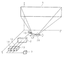
図8は、従来の投影型画像表示装置の構成を示す模式図である。図において101R、101G及び101Bは、それぞれ赤色、緑色及び青色のレーザ光を発するレーザ光源である。レーザ光源101R、101G及び101Bからそれぞれ出射した3色のレーザ光は、光学系102にて径の小さな平行光に収束されて第1光偏向素子110へ出射される。第1光偏向素子110は、1つの回動軸を有しており、ミラー面を回動軸にて回動させることにより、光学系102からのレーザ光を偏向して第2光偏向素子120へ反射する。第2光偏向素子120は、第1光偏向素子110の回動軸に対して直交する回動軸を有しており、ミラー面を回動軸にて回動させることにより、第1光偏向素子110からのレーザ光を更に偏向してスクリーン105へ出射する。
FIG. 8 is a schematic diagram showing a configuration of a conventional projection type image display apparatus. In the figure,
この構成により投影型画像表示装置は、径の小さいレーザ光を第1光偏向素子110により図中のy方向に広がりを持つ光に変換し、この光を更に第2光偏向素子120によりz方向に広がりを持つ光に変換することができる。即ち、投影型画像表示装置は、第1光偏向素子110が画像の水平方向の走査を行い、第2光偏向素子120が垂直方向の走査を行って、スクリーン105に画像を投影して表示することができる。
With this configuration, the projection-type image display apparatus converts the laser beam having a small diameter into light having a spread in the y direction in the figure by the first
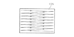
図9は、従来の投影型画像表示装置による画像表示を説明するための模式図であり、スクリーン105に投影される画像の構成を模式的に図示したものである。投影型画像表示装置は、スクリーン105の左から右へ、右から左へを順に繰り返しながら、上から下へ順にレーザ光を走査することによって、スクリーン105に1つの画像を形成する。スクリーン105の左から右へ、右から左への走査は第1光偏向素子110の回動により実現され、上から下への走査は第2光偏向素子120の回動により実現される。
FIG. 9 is a schematic diagram for explaining image display by a conventional projection-type image display device, and schematically shows a configuration of an image projected on the
また投影型画像表示装置が動画像の表示を行う場合には、1秒間に30〜60程度の数の画像を連続的に表示する必要がある。このとき、第2光偏向素子120の回動速度は、1秒間に表示する画像数に依存する。これに対して、第1光偏向素子110の回動速度は、1秒間に表示する画像数と、1つの画像の解像度(水平方向のライン数)との積に依存するため、第1光偏向素子110は高速動作が要求される。例えば1920×1080の解像度の画像を1秒間に60回表示する場合、第2光偏向素子120は1秒間に60回の回動を行えばよいが、第1光偏向素子110は1080÷2×60=32400回の回動を行う必要がある。
When the projection type image display apparatus displays a moving image, it is necessary to continuously display about 30 to 60 images per second. At this time, the rotation speed of the second
ここで、光偏向素子の回動とはシーソーのように揺れ動くこと、即ち360°以下の所定角範囲内で正逆回転することであり、1回の回動とは正逆回転の1往復分をいうものとする。よって、図9に示すように第1光偏向素子110は1回の回動で2ライン分の走査を行うことができるため、第1光偏向素子110の1秒間の回動数は、水平方向のライン数の半分と1秒間に表示する画像数との積である。
Here, the rotation of the light deflection element means that it swings like a seesaw, that is, it rotates in the forward and reverse directions within a predetermined angle range of 360 ° or less, and one rotation means one reciprocal rotation in the forward and reverse directions. It shall be said. Therefore, as shown in FIG. 9, the first
投影型画像表示装置において、表示する画像のサイズを大きくするためには光偏向素子の回動角度を大きくする必要がある。しかしながら、光偏向素子の回動角度を大きくすると回動速度を高速化することが困難となるため表示する画像の解像度又は1秒間に表示する画像数を低減しなければならず、表示する画像の画質が低下するという問題がある。逆に、画質を高めるために光偏向素子の回動速度を高速化すると光偏向素子の回動角度を大きくすることが困難となるため、表示する画像のサイズが小さくなるという問題がある。即ち、従来の投影型画像表示装置では、光偏向素子の回動角度の拡大と回動速度の高速化とが背反の関係にあり、表示する画像の高画質化と画像サイズの拡大との両方を実現することは困難であった。 In the projection type image display apparatus, in order to increase the size of an image to be displayed, it is necessary to increase the rotation angle of the light deflection element. However, if the rotation angle of the light deflection element is increased, it is difficult to increase the rotation speed. Therefore, the resolution of the image to be displayed or the number of images to be displayed per second must be reduced. There is a problem that the image quality deteriorates. On the contrary, if the rotation speed of the light deflection element is increased in order to improve the image quality, it becomes difficult to increase the rotation angle of the light deflection element, which causes a problem that the size of the image to be displayed is reduced. In other words, in the conventional projection type image display device, the enlargement of the rotation angle of the light deflection element and the increase of the rotation speed are contradictory, and both the improvement in the image quality of the displayed image and the enlargement of the image size are achieved. It was difficult to realize.
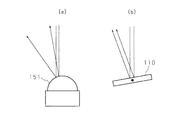
特許文献1においては、直交する2方向に移動自在に支持されたステージに曲面ミラーを設け、この曲面ミラーを直行する2方向に移動させてレーザ光を走査する構成の光スキャナが提案されている。図10は、特許文献1に係る光スキャナの構成を示す模式図であり、(a)に特許文献1の光スキャナが備える曲面ミラーを示し、(b)には比較のために従来の投影型画像表示装置が備える第1光偏向素子110を示してある。特許文献1に係る光スキャナは、略半球形の曲面ミラー151を備えており、曲面ミラー151を平行移動させることによって入射したレーザ光の反射角度を変化させることができる。これにより、従来の投影型画像表示装置が備える第1光偏向素子110の回動による反射角度の変化と比較して、特許文献1に係る光スキャナはより大きな角度範囲でレーザ光を反射することができ、レーザ光による走査角度を拡大することができるため、画像をより大きく表示することができる。
しかしながら、特許文献1に係る光スキャナは、略半球形の曲面ミラー151を用いてレーザ光を反射するため、レーザ光が広がりを持って反射されるという問題がある。図11は、特許文献1に係る光スキャナの問題点を説明するための模式図であり、(a)に特許文献1の光スキャナにおける曲面ミラー151の入射及び反射を示し、(b)には比較のために従来の投影型画像表示装置の第1光偏向素子110の入射及び反射を示してある。例えば従来の投影型画像表示装置の第1光偏向素子110には光学系102から赤色、緑色及び青色の3つのレーザ光が平行光として入射される。第1光偏向素子110のミラー面は平面であるため、平行光として入射した平行光は、平行光として反射される。
However, since the optical scanner according to
これに対して曲面ミラー151の場合には、ミラー面が曲面であるため、レーザ光が入射する位置によってミラー面に対する入射角度が異なり、レーザ光の反射方向が異なる。よって、曲面ミラー151に平行光が入射した場合であっても、反射されるレーザ光は平行光でなく、スクリーンに投影されるレーザ光のスポット径が大きくなるため、投影される画像において隣接する画素を表示するためのレーザ光が重なり合い、投影される画像がぼやけるため、表示画質が劣化するという問題が生じる。
On the other hand, in the case of the
本発明は、斯かる事情に鑑みてなされたものであって、その目的とするところは、表示画質を劣化させることなく、レーザ光の走査角度を拡大して、より大きな画像を投影して表示することができる投影型画像表示装置を提供することにある。 The present invention has been made in view of such circumstances, and an object of the present invention is to enlarge a scanning angle of a laser beam and project and display a larger image without deteriorating display image quality. It is an object of the present invention to provide a projection type image display apparatus that can do this.
本発明に係る投影型画像表示装置は、光源からの光を光偏向素子により偏向して投影することにより画像を表示する投影型画像表示装置において、ミラー面及び該ミラー面を回動させる回動軸を有し、該回動軸で回動する前記ミラー面にて光を反射することにより光の偏向を行う第1光偏向素子と、ミラー面及び該ミラー面をそれぞれ異なる方向に回動させる2つの回動軸を有し、該2つの回動軸で回動する前記ミラー面にて光を反射することにより光の偏向を行う第2光偏向素子とを備え、前記第1光偏向素子が反射した光が前記第2光偏向素子へ入射するように、前記第1光偏向素子及び第2光偏向素子が配設してあることを特徴とする。 A projection-type image display apparatus according to the present invention is a projection-type image display apparatus that displays an image by deflecting light from a light source with a light deflection element and projecting the light. A first light deflection element having a shaft and deflecting light by reflecting light on the mirror surface rotated by the rotation shaft; and the mirror surface and the mirror surface are rotated in different directions. A second optical deflection element that has two pivot axes and deflects light by reflecting light on the mirror surface that pivots around the two pivot axes, and the first optical deflection element The first light deflecting element and the second light deflecting element are arranged so that the light reflected by the light enters the second light deflecting element.
また、本発明に係る投影型画像表示装置は、前記第1光偏向素子のミラー面の回動及び前記第2光偏向素子の一の回動軸によるミラー面の回動により、表示する画像の水平方向の走査を行い、前記第2光偏向素子の他の回動軸によるミラー面の回動により、表示する画像の垂直方向の走査を行うようにしてあることを特徴とする。 Further, the projection type image display apparatus according to the present invention provides an image to be displayed by rotating the mirror surface of the first light deflection element and rotating the mirror surface by one rotation axis of the second light deflection element. Scanning in the horizontal direction is performed, and scanning of the image to be displayed is performed in the vertical direction by rotation of the mirror surface by the other rotation axis of the second light deflection element.
また、本発明に係る投影型画像表示装置は、前記第2光偏向素子の前記一の回動軸によるミラー面の回動と、前記第1光偏向素子のミラー面の回動とが同位相で行われるようにしてあることを特徴とする。 In the projection-type image display device according to the present invention, the rotation of the mirror surface by the one rotation axis of the second light deflection element and the rotation of the mirror surface of the first light deflection element are in phase. It is made to be performed by.
また、本発明に係る投影型画像表示装置は、前記第2光偏向素子を複数備えることを特徴とする。 The projection-type image display device according to the present invention includes a plurality of the second light deflection elements.
また、本発明に係る投影型画像表示装置は、複数の前記第2光偏向素子がそれぞれ有する一の回動軸が互いに平行に配され、他の回動軸が一致して配されていることを特徴とする。 Further, in the projection type image display device according to the present invention, one rotation axis included in each of the plurality of second light deflection elements is arranged in parallel to each other, and the other rotation axes are arranged to coincide with each other. It is characterized by.
本発明においては、少なくとも1つの回動軸を有する第1光偏向素子と、2つの回動軸を有する第2光偏向素子とを用い、光源からの光を第1光偏向素子が反射して第2光偏向素子へ入射させ、この光を第2光偏向素子が反射して投影することによって、投影型画像表示装置は画像表示を行う。第2光偏向素子を2つの回動軸で回動させることによって、走査角度の拡大を実現することができる。
例えば、第1光偏向素子の回動と、第2光偏向素子の一の回動軸での回動とにより画像の水平方向の走査を同位相で行い、第2光偏向素子の他の回動軸での回動により画像の垂直方向の走査を行うことができる。これにより、第1光偏向素子の回動角度を拡大することなく、投影型画像表示装置における画像の水平方向の走査角度を拡大することができるため、大きな画像表示と、表示する画像の高画質化との両方を実現することが可能となる。
In the present invention, a first light deflection element having at least one rotation axis and a second light deflection element having two rotation axes are used, and light from the light source is reflected by the first light deflection element. The projection type image display apparatus displays an image by making the light incident on the second light deflecting element and projecting the light reflected by the second light deflecting element. The scanning angle can be expanded by rotating the second light deflection element with two rotation axes.
For example, the horizontal scanning of the image is performed in the same phase by the rotation of the first light deflection element and the rotation of one rotation axis of the second light deflection element, and the other times of the second light deflection element. Scanning in the vertical direction of the image can be performed by rotation on the moving axis. Accordingly, since the horizontal scanning angle of the image in the projection type image display device can be expanded without increasing the rotation angle of the first light deflection element, large image display and high image quality of the displayed image can be achieved. Both can be realized.
また、投影型画像表示装置が複数の第2光偏向素子を備える構成とすることができる。このとき、各第2光偏向素子が有する水平方向の走査を行うための一の回動軸を平行に配し、他の回動軸を一致させて、複数の第2光偏向素子を並べてもよい。複数の第2光偏向素子を備えることによって、第2光偏向素子を1つ備える場合と比較して、各第2光偏向素子を小型化することができ、回動速度を高速化することができるため、表示する画像の更なる高画質化を実現することができる。 In addition, the projection type image display apparatus can include a plurality of second light deflection elements. At this time, even if a plurality of second light deflection elements are arranged by arranging one rotation axis for performing horizontal scanning of each second light deflection element in parallel and aligning the other rotation axes. Good. By providing a plurality of second light deflection elements, it is possible to reduce the size of each second light deflection element and increase the rotation speed as compared with the case where one second light deflection element is provided. Therefore, it is possible to realize further higher image quality of the displayed image.
本発明による場合は、少なくとも1つの回動軸を有する第1光偏向素子が光源からの光を反射して第2光偏向素子へ入射させ、2つの回動軸を有する第2光偏向素子がこの光を反射して投影することで画像表示を行う構成とすることにより、第1光偏向素子の回動角度を拡大することなく、投影型画像表示装置の走査角度を拡大することができる。よって、第1光偏向素子の回動速度を高速化することができるため高画質な画像表示を行うことができると共に、走査角度の拡大によって大きな画像を表示することができる。 In the case of the present invention, the first light deflection element having at least one rotation axis reflects the light from the light source to enter the second light deflection element, and the second light deflection element having two rotation axes is provided. By adopting a configuration in which image display is performed by reflecting and projecting this light, the scanning angle of the projection-type image display device can be expanded without increasing the rotation angle of the first light deflection element. Therefore, since the rotation speed of the first light deflection element can be increased, high-quality image display can be performed, and a large image can be displayed by increasing the scanning angle.
(実施の形態1)
以下、本発明をその実施の形態を示す図面に基づき具体的に説明する。図1は、本発明の実施の形態1に係る投影型画像表示装置の構成を示す模式図である。図において1R、1G及び1Bは、それぞれ赤色、緑色及び青色のレーザ光を発するレーザ光源であり、レーザ変調部3により発光制御がなされている。レーザ変調部3は、図示は省略するが表示画像に係る画像信号が与えられており、この画像信号に応じて各色のレーザ光の強度を制御する。
(Embodiment 1)
Hereinafter, the present invention will be specifically described with reference to the drawings showing embodiments thereof. FIG. 1 is a schematic diagram showing a configuration of a projection type image display apparatus according to
レーザ光源1R、1G及び1Bからそれぞれ出射した各色のレーザ光は光学系2に入射する。光学系2は、レーザ光源1R、1G及び1Bからの3つのレーザ光を略平行且つビーム径の小さなレーザ光に成形することによって、3つのレーザ光を同一光軸上に合成する。レーザ変調部3が3つのレーザ光の強度を制御し、光学系2が3つのレーザ光を合成することによって、表示画像の各画素の色に合成されたレーザ光が光学系2から第1光偏向素子10へ出射される。光学系2から出射されたレーザ光は、第1光偏向素子10及び第2光偏向素子20にて偏向され、スクリーン5に画像として投影される。
The laser beams of the respective colors emitted from the
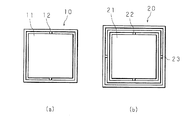
図2は、本発明の実施の形態1に係る投影型画像表示装置の第1光偏向素子10及び第2光偏向素子20の構成を示す模式図である。第1光偏向素子10は、レーザ光を反射するミラー面11と、このミラー面11を回動させる少なくとも1つの回動軸12とを有している(図2(a)参照)。また第2光偏向素子20は、レーザ光を反射するミラー面21と、このミラー面21を回動させる第1回動軸22と、この第1回動軸22に略直交してミラー面21を回動させる第2回動軸23とを有している(図2(b)参照)。第1回動軸22による回動と、第2回動軸23による回動とは独立して行うことができる。なお本実施の形態において回動とは、例えばシーソーのように回動軸を中心にして揺れ動く動作、即ち360°以下の所定角範囲内で正逆回転する動作を示すものとする。
FIG. 2 is a schematic diagram showing configurations of the first
第1光偏向素子10及び第2光偏向素子20が有するミラー面を回動させる方法には、電磁方式、静電方式及び圧電方式等の種々の方法があるが、本発明においてはいずれの方法でミラー面を回動させてもよい。図示は省略するが、投影型画像表示装置は第1光偏向素子10及び第2光偏向素子20が有するミラー面をいずれかの方法で回動させる光偏向素子制御部を備えており、光偏向素子制御部によりミラー面の回動速度及び回動方向等が制御されている。
There are various methods such as an electromagnetic method, an electrostatic method, and a piezoelectric method for rotating the mirror surfaces of the first
また、投影型画像表示装置において、第1光偏向素子10は、光学系2から出射されたレーザ光に対して回動軸12が90°より小さい所定角度で交差する位置に配設されている。また第2光偏向素子20は、第1回動軸22が光学系2から出射されたレーザ光に対して略平行となり、第1回動軸22と第1光偏向素子10の回動軸12の延長線とが90°より小さい所定角度で交差するように、且つ、第2回動軸23が光学系2から出射されたレーザ光に対して略垂直となるように、投影型画像表示装置において配設されている。換言すれば、図1において光学系2のレーザの出射方向をx方向とし、画像が投影されるスクリーン5の水平方向をy方向とし、スクリーン5の垂直方向をz方向とした場合に、xy平面に対する第1光偏向素子10の回動軸12及び第2光偏向素子20の第1回動軸22の投影像が一直線上となるように、第1光偏向素子10及び第2光偏向素子20が配設されている。
Further, in the projection type image display device, the first
光学系2から出射されたレーザ光は、第1光偏向素子10のミラー面11に入射する。第1光偏向素子10のミラー面11は回動軸12にて回動しており、図中のx方向に入射した光はy方向に広がりを持つ光に変換されて第2光偏向素子10へ反射される。これにより、第1光偏向素子10によって、スクリーン5に投影される画像の水平方向に関する(前段の)走査が行われる。
The laser light emitted from the
第1光偏向素子10から出射されたy方向に広がりを持つ光は、第2光偏向素子20のミラー面21に入射する。第2光偏向素子20のミラー面21は第1回動軸22にて回動しており、第1光偏向素子10からの光はy方向に更に広がりを持つ光に変換されてスクリーン5へ反射される。これにより、第2光偏向素子20によって、スクリーン5に投影される画像の水平方向に関する(後段の)走査が行われる。即ち、本発明に係る投影型画像表示装置は、第1光偏向素子10のみでなく、第1光偏向素子10及び第2光偏向素子20の両方を利用して水平方向の走査を行う。
The light having a spread in the y direction emitted from the first
なお、第1光偏向素子10の回動と、第2光偏向素子20の第1回動軸22による回動とは同位相で行う。即ち、第1光偏向素子10の回動が一端側に到達した場合には第2光偏向素子20の回動も一端側に到達してスクリーン5の一端側に光を反射し、第1光偏向素子10の回動が中央位置に到達した場合には第2光偏向素子20の回動も中央位置に到達してスクリーン5の中央位置に光を反射し、第1光偏向素子10の回動が他端側に到達した場合には第2光偏向素子20の回動も他端側に到達してスクリーン5の他端側に光を反射するように、第1光偏向素子10の回動と、第2光偏向素子20の第1回動軸22による回動とは回動速度、回動方向及び回動タイミング等が調整してある。
The rotation of the first
また、第2光偏向素子20のミラー面21は第2回動軸23にて回動しており、第1光偏向素子10からの光はz方向に広がりを持つ光に変換されてスクリーン5へ反射される。これにより、第2光偏向素子によって、スクリーン5に投影される画像の垂直方向に関する走査が行われる。即ち、本発明に係る投影型画像表示装置では、第2光偏向素子10は水平方向及び垂直方向の両方向に関する走査を行う。よって、投影型画像表示装置は、第1光偏向素子10及び第2光偏向素子20により水平方向及び垂直方向の走査を行うことができ、スクリーン5へ略矩形の画像を投影して表示することができる。
Further, the
図3は、投影型画像表示装置による画像表示を説明するための模式図であり、スクリーン5に投影される画像(動画)の構成を模式的に図示したものである。投影型画像表示装置は、スクリーン5の左から右へ、右から左へを順に繰り返しながら、上から下へ順にレーザ光を走査することによって、人間の目には残像効果によってレーザ光が二次元画像として認識され、スクリーン5に1つの画像を形成することができる。スクリーン5の左から右へ、右から左への走査は、第1光偏向素子10の回動と、第2光偏向素子20の第1回動軸22による回動とによって実現される。またスクリーン5の上から下への走査は、第2光偏向素子20の第2回動軸23による回動によって実現される。
FIG. 3 is a schematic diagram for explaining image display by the projection-type image display device, and schematically shows a configuration of an image (moving image) projected on the
なお、投影型画像表示装置によるレーザ光の走査の順は図3に示すものに限らない。例えば、スクリーン5の上から下へ、下から上へを順に繰り返しながら、左から右へ順にレーザ光を走査する方法など、その他の方法であってもよい。投影型画像表示装置は第1光偏向素子10及び第2光偏向素子20の回動を制御する光偏向素子制御部を備えているが、この光偏向素子制御部による回動速度及び回動方向等の制御を変更することによって、レーザ光の走査の順を変更することができる。また、投影型画像表示装置は、表示する画像に係る画像信号が入力され、入力された画像信号をレーザ光の走査順に応じて変換する画像信号処理部(図示は省略する)を備えている。この画像信号処理部は、入力された画像信号に含まれる各画素の情報をレーザ光の走査順に並べ替えることによって画像信号の変換を行い、変換後の画像信号をレーザ変調部3へ与える。第1光偏向素子10及び第2光偏向素子20によるレーザ光の走査順に応じて画像信号処理部が適切に画像信号を変換することによって、レーザ光の走査をいかなる順序で行ったとしても投影型画像表示装置は画像表示を適切に行うことができる。
Note that the order of scanning of the laser light by the projection type image display apparatus is not limited to that shown in FIG. For example, other methods such as a method of scanning the laser light sequentially from left to right while sequentially repeating from the top to the bottom and from the bottom to the top of the
また、例えば投影型画像表示装置が1920×1080の高精細な画像を1秒間に60回表示して動画表示を行う場合、図3に示す順にレーザ光の走査を行うと、第1光偏向素子10は1秒間に1080÷2×60=32400回の回動を行う必要がある。このため、図8に示した従来の投影型画像表示装置では、第1光偏向素子110の回動角度の拡大と回動速度の高速化とが背反の関係にあり、表示画像の高画質化と画像サイズの拡大との両方を実現することが困難であった。
For example, when the projection type image display device displays a high-definition image of 1920 × 1080 60 times per second to display a moving image, the first light deflection element is obtained by performing laser light scanning in the order shown in FIG. 10 needs to rotate 1080 ÷ 2 × 60 = 32400 times per second. For this reason, in the conventional projection type image display apparatus shown in FIG. 8, the enlargement of the rotation angle of the first
これに対して本発明に係る投影型画像表示装置は、第1光偏向素子10及び第2光偏向素子20の2つの光偏向素子を用いて水平方向の走査を行う構成であるため、第1光偏向素子10の回動角度及び回動速度が従来と同じであっても、第2光偏向素子20により水平方向の走査角度を拡大することができる。なお、垂直方向の走査は第2光偏向素子20の回動のみによって行うが、垂直方向の回動は1秒間に60回のみでよいため、走査角度の拡大は容易である。
On the other hand, the projection type image display apparatus according to the present invention is configured to perform horizontal scanning using the two light deflecting elements, the first
図4は、水平方向に関するレーザ光の走査角度を説明するための模式図であり、(a)に本発明に係る投影型画像表示装置の場合を示し、(b)には比較のために従来の投影型画像表示装置の場合を示してある。図4においては、第1光偏向素子10(110)から第2光偏向素子20(120)までの距離をd1とし、第2光偏向素子20(120)からスクリーン5(105)までの距離をd2とする。また、第1光偏向素子10(110)によるレーザ光の水平方向の走査角度をαとし、第2光偏向素子20によるレーザ光の水平方向の走査角度をβとする。
FIG. 4 is a schematic diagram for explaining the scanning angle of the laser beam with respect to the horizontal direction. FIG. 4A shows the case of the projection type image display apparatus according to the present invention, and FIG. The case of the projection type image display apparatus is shown. In FIG. 4, the distance from the first light deflection element 10 (110) to the second light deflection element 20 (120) is d1, and the distance from the second light deflection element 20 (120) to the screen 5 (105) is the distance. Let d2. The horizontal scanning angle of the laser light by the first light deflection element 10 (110) is α, and the horizontal scanning angle of the laser light by the second
光学系2からのレーザ光は、第1光偏向素子10(110)にて水平方向に±αの走査角度だけ広げられて、第2光偏向素子20(120)へ入射する。従来の投影型画像表示装置では、第2光偏向素子120は水平方向の走査に寄与しないため、スクリーン105へは水平方向に関して±αの広がりで光が投影される(図4(b)参照)。このとき、スクリーン105に投影される画像の水平方向に関する幅hは、以下の(式1)で表される。
h = 2×(d1+d2)×tanα …(式1)
The laser light from the
h = 2 × (d1 + d2) × tan α (Expression 1)
本発明に係る投影型画像表示装置では、第1光偏向素子10が出射した光は、第2光偏向素子20にて水平方向に±βの走査角度だけ更に広げられてスクリーン5へ投影される(図4(a)参照)。このとき、スクリーン5に投影される画像の水平方向に関する幅hは、以下の(式2)で表される。
h = 2×{d1×tanα+d2×tan(α+β)} …(式2)
In the projection type image display apparatus according to the present invention, the light emitted from the first
h = 2 × {d1 × tan α + d2 × tan (α + β)} (Expression 2)
ここで、例えばd1=5mm、d2=50cm、α=10°、β=10°とする。上記(式1)より、従来の投影型画像表示装置が投影する画像の水平方向に関する幅h≒17.8cmである。また上記(式2)より、本発明に係る投影型画像表示装置が投影する画像の水平方向に関する幅h≒36.6cmである。よって、本発明に係る投影型画像表示装置は、従来の投影型画像表示装置と比較して、水平方向に約2倍の幅を有する大きな画像を表示することができる。 Here, for example, d1 = 5 mm, d2 = 50 cm, α = 10 °, and β = 10 °. From the above (Equation 1), the width h in the horizontal direction of the image projected by the conventional projection type image display apparatus is approximately 17.8 cm. Further, from the above (Equation 2), the width h in the horizontal direction of the image projected by the projection type image display apparatus according to the present invention is approximately 36.6 cm. Therefore, the projection type image display apparatus according to the present invention can display a large image having a width approximately twice as large as that of the conventional projection type image display apparatus.
以上の構成の本発明に係る投影型画像表示装置においては、1つの回動軸12を有する第1光偏向素子10が光学系2からのレーザ光を水平方向に走査して第2光偏向素子20へ入射させ、2つの回動軸22及び23を有する第2光偏向素子20がこの光を水平方向及び垂直方向に走査してスクリーン5へ投影する構成とすることにより、第1光偏向素子10の回動角度を拡大することなく、水平方向に関する走査角度を拡大することができる。よって、第1光偏向素子10の回動速度を高速化することができ、高画質な画像表示を行うことができると共に、走査角度の拡大によって大きな画像を表示することができる。
In the projection type image display apparatus according to the present invention having the above-described configuration, the first
また例えば、第1光偏向素子10を低速に且つ広い角度で回動させ、第2光偏向素子20を第1回動軸22にて低速に且つ広い角度で回動させ、第2光偏向素子20を第2回動軸23にて高速且つ狭い角度で回動させることができるが、この場合に投影型画像表示装置は水平方向に長い画像を表示することができる。このように、本発明に係る投影型画像表示装置は、第1光偏向素子10の回動と、第2光偏向素子20の2つの回動軸による回動とを適宜に制御することによって、従来の投影型画像表示装置では表示することが容易でないサイズ又は形状の画像を表示することができる。
Further, for example, the first
(実施の形態2)
図5は、本発明の実施の形態2に係る投影型画像表示装置の構成を示す模式図である。なお、図5においては投影型画像表示装置が備えるレーザ光源1R、1G及び1B、光学系2並びにレーザ変調部3は図示を省略してある。また、図6は、本発明の実施の形態2に係る投影型画像表示装置の第2光偏向素子の構成を示す模式図である。
(Embodiment 2)
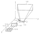
FIG. 5 is a schematic diagram showing a configuration of a projection type image display apparatus according to
実施の形態2に係る投影型画像表示装置は、1つの第1光偏向素子10と、3つの第2光偏向素子20a〜20cとを備えている。3つの第2光偏向素子20a〜20cは、光学系2からのレーザ光に対して略直交する方向(y方向)に並べて配され、レーザ光を反射するミラー面21a〜21cをそれぞれ有している。各ミラー面21a〜21cは、略平行に配された第1回動軸22a〜22cにてそれぞれ独立して回動させることができ、且つ、第1回動軸22a〜22cに略直交する共通の第2回動軸23にて揃って回動させることができる。なお、第1回動軸22a〜22cによる各ミラー面21a〜21cの回動は、同一方向且つ同位相となるように行われる。
The projection type image display apparatus according to
光学系2からのレーザ光は第1光偏向素子10にてy方向に広がりを持つ光として反射され(水平方向に走査され)、第2光偏向素子20a〜20cへ入射する。このとき、第1光偏向素子20にて反射された光は、第1光偏向素子10の回動位置に応じて3つの第2光偏向素子20a〜20cのいずれか1つに入射する。3つの第2光偏向素子20a〜20cのうち、左側に配された第2光偏向素子20aに入射した光はスクリーン5の左側に反射されて画像の左部分を形成し、中央に配された第2光偏向素子20bに入射した光はスクリーン5の中央に反射された画像の中央部分を形成し、右側に配された第2光偏向素子20cに入射した光はスクリーン5の右側に反射されて画像の右部分を形成する。これにより、スクリーン5には水平方向に大きな1つの画像が形成される。
The laser light from the
このように、投影型画像表示装置が複数の第2光偏向素子20a〜20cを備えることによって、サイズが大きな1つの第2光偏向素子20(実施の形態1参照)を備える場合と比較して、第2光偏向素子の水平方向の走査に係る回動をより高速化することができるという利点がある。図7は、レーザ光のスポット半径と第2光偏向素子20のサイズとの関係を説明するための模式図であり、光学系2からのレーザ光が第1光偏向素子10にて反射されてから第2光偏向素子20へ入射するまでを模式的に示したものである。なお、図7においては、第1光偏向素子10から第2光偏向素子20までの距離をdとし、第1光偏向素子10により光学系2からのレーザ光が±θの広がりを持って反射されるものとし、光学系2から第1光偏向素子10へ入射するレーザ光のスポット半径をrとする。
As described above, the projection type image display apparatus includes a plurality of second light deflection elements 20a to 20c, so that the projection type image display apparatus includes one second light deflection element 20 (see Embodiment 1) having a large size. There is an advantage that the rotation of the second light deflection element in the horizontal direction can be further accelerated. FIG. 7 is a schematic diagram for explaining the relationship between the spot radius of the laser light and the size of the second
このとき、第2光偏向素子20におけるレーザ光の広がり(水平方向の幅)hは、以下の(式3)で表される。
h = 2×(d×tanθ+r) …(式3)
よって、第2光偏向素子20は少なくとも(式3)で表される幅hの大きさが必要である。例えばθ=10°、d=5mm、r=0.1mmとすると、h≒1.96mmである。
At this time, the spread (horizontal width) h of the laser light in the second
h = 2 × (d × tan θ + r) (Formula 3)
Therefore, the second
光偏向素子を高速に回動させる場合、共振周波数に応じた回動を行うことが好ましい。慣性モーメントなどの物理的性質により、光偏向素子のサイズが小さい方が共振周波数は大きくなる。従って、光偏向素子のサイズを小さくすることによって、光偏向素子の回動を高速化することができ、より高精細な画像表示が可能となる。 When the optical deflection element is rotated at high speed, it is preferable to perform rotation according to the resonance frequency. Due to physical properties such as moment of inertia, the resonance frequency increases as the size of the optical deflection element decreases. Therefore, by reducing the size of the light deflection element, the rotation of the light deflection element can be speeded up, and higher-definition image display is possible.
実施の形態2に係る投影型画像表示装置は、複数の第2光偏向素子20a〜20cを備える構成であるため、各第2光偏向素子20a〜20cのサイズを小さくすることができる。よって、サイズが大きな1つの第2光偏向素子20より、サイズの小さな複数の第2光偏向素子20a〜20cは高速に回動を行うことができるため、実施の形態2に係る投影型画像表示装置はより高精細な画像表示を行うことができる。
Since the projection type image display apparatus according to
なお、実施の形態2においては投影型画像表示装置が3つの第2光偏向素子20a〜20cを備える構成としたが、これに限るものではなく、2つ又は4つ以上の第2光偏向素子を備える構成であってもよい。 In the second embodiment, the projection type image display device includes three second light deflection elements 20a to 20c. However, the present invention is not limited to this, and two or four or more second light deflection elements are used. May be provided.
1R、1G、1B レーザ光源(光源)
2 光学系
3 レーザ変調部
5 スクリーン
10 第1光偏向素子
11 ミラー面
12 回動軸
20、20a、20b、20c 第2光偏向素子
21、21a、21b、21c ミラー面
22、22a、22b、22c 第1回動軸
23 第2回動軸
1R, 1G, 1B Laser light source (light source)
2
Claims (5)
ミラー面及び該ミラー面を回動させる回動軸を有し、該回動軸で回動する前記ミラー面にて光を反射することにより光の偏向を行う第1光偏向素子と、
ミラー面及び該ミラー面をそれぞれ異なる方向に回動させる2つの回動軸を有し、該2つの回動軸で回動する前記ミラー面にて光を反射することにより光の偏向を行う第2光偏向素子と
を備え、
前記第1光偏向素子が反射した光が前記第2光偏向素子へ入射するように、前記第1光偏向素子及び第2光偏向素子が配設してあること
を特徴とする投影型画像表示装置。 In a projection-type image display device that displays an image by deflecting and projecting light from a light source by a light deflection element,
A first light deflection element having a mirror surface and a pivot shaft for pivoting the mirror surface, and deflecting light by reflecting light on the mirror surface pivoted by the pivot shaft;
A mirror surface and two rotation shafts for rotating the mirror surface in different directions, respectively, and deflecting light by reflecting light on the mirror surface rotated by the two rotation shafts. With two light deflection elements,
The projection type image display, wherein the first light deflection element and the second light deflection element are arranged so that the light reflected by the first light deflection element is incident on the second light deflection element. apparatus.
前記第2光偏向素子の他の回動軸によるミラー面の回動により、表示する画像の垂直方向の走査を行うようにしてあること
を特徴とする請求項1に記載の投影型画像表示装置。 The image to be displayed is scanned in the horizontal direction by the rotation of the mirror surface of the first light deflection element and the rotation of the mirror surface by one rotation axis of the second light deflection element,
2. The projection type image display device according to claim 1, wherein scanning of an image to be displayed is performed in a vertical direction by rotating a mirror surface by another rotating shaft of the second light deflection element. .
を特徴とする請求項2に記載の投影型画像表示装置。 The rotation of the mirror surface by the one rotation axis of the second light deflection element and the rotation of the mirror surface of the first light deflection element are performed in the same phase. Item 3. The projection type image display device according to Item 2.
を特徴とする請求項1から請求項3までのいずれか1つに記載の投影型画像表示装置。 The projection-type image display device according to claim 1, comprising a plurality of the second light deflection elements.
を特徴とする請求項4に記載の投影型画像表示装置。 5. The projection image according to claim 4, wherein one rotation axis of each of the plurality of second light deflection elements is arranged in parallel to each other, and the other rotation axes are arranged to coincide with each other. Display device.
Priority Applications (2)
| Application Number | Priority Date | Filing Date | Title |
|---|---|---|---|
| JP2008122541A JP2009271375A (en) | 2008-05-08 | 2008-05-08 | Projection image display |
| PCT/JP2009/058475 WO2009136588A1 (en) | 2008-05-08 | 2009-04-30 | Projection image display device |
Applications Claiming Priority (1)
| Application Number | Priority Date | Filing Date | Title |
|---|---|---|---|
| JP2008122541A JP2009271375A (en) | 2008-05-08 | 2008-05-08 | Projection image display |
Publications (2)
| Publication Number | Publication Date |
|---|---|
| JP2009271375A true JP2009271375A (en) | 2009-11-19 |
| JP2009271375A5 JP2009271375A5 (en) | 2010-12-09 |
Family
ID=41264643
Family Applications (1)
| Application Number | Title | Priority Date | Filing Date |
|---|---|---|---|
| JP2008122541A Pending JP2009271375A (en) | 2008-05-08 | 2008-05-08 | Projection image display |
Country Status (2)
| Country | Link |
|---|---|
| JP (1) | JP2009271375A (en) |
| WO (1) | WO2009136588A1 (en) |
Families Citing this family (1)
| Publication number | Priority date | Publication date | Assignee | Title |
|---|---|---|---|---|
| JP6770502B2 (en) * | 2017-11-22 | 2020-10-14 | キヤノン株式会社 | Communication devices, display devices, their control methods, programs and display systems |
Citations (2)
| Publication number | Priority date | Publication date | Assignee | Title |
|---|---|---|---|---|
| JPS5397447A (en) * | 1977-02-04 | 1978-08-25 | Canon Inc | Optical scanning system |
| JP2004517351A (en) * | 2000-11-03 | 2004-06-10 | マイクロビジョン インコーポレイテッド | Frequency adjustable resonant scanning device and method of making adjustable |
Family Cites Families (1)
| Publication number | Priority date | Publication date | Assignee | Title |
|---|---|---|---|---|
| JP2007163817A (en) * | 2005-12-14 | 2007-06-28 | Canon Inc | Optical deflector and optical equipment using the same |
-
2008
- 2008-05-08 JP JP2008122541A patent/JP2009271375A/en active Pending
-
2009
- 2009-04-30 WO PCT/JP2009/058475 patent/WO2009136588A1/en active Application Filing
Patent Citations (2)
| Publication number | Priority date | Publication date | Assignee | Title |
|---|---|---|---|---|
| JPS5397447A (en) * | 1977-02-04 | 1978-08-25 | Canon Inc | Optical scanning system |
| JP2004517351A (en) * | 2000-11-03 | 2004-06-10 | マイクロビジョン インコーポレイテッド | Frequency adjustable resonant scanning device and method of making adjustable |
Also Published As
| Publication number | Publication date |
|---|---|
| WO2009136588A1 (en) | 2009-11-12 |
Similar Documents
| Publication | Publication Date | Title |
|---|---|---|
| US6971748B2 (en) | High-resolution display including pixel moving optical system | |
| JP3571016B2 (en) | Micro mirror device and projector employing the same | |
| JP5091112B2 (en) | Image projection device | |
| JP4731938B2 (en) | Image display device / projection optical system | |
| US20070296645A1 (en) | Display apparatus using laser and method of using the same | |
| EP1674914A1 (en) | Optical scanning device and image display apparatus | |
| JP2005352488A (en) | Optical system for scanning angle expansion, and scanning apparatus provided with the same | |
| JP2004252012A (en) | Projection type display optical system | |
| JP2007293226A (en) | Laser display apparatus | |
| JP2019039995A (en) | Image projection device | |
| JP2005107179A (en) | Scanning type picture display device | |
| JP4967573B2 (en) | Image projection device | |
| JP2009157111A (en) | Image display device | |
| JP4264570B2 (en) | Projection-type image display device using deflection device | |
| JP4095428B2 (en) | Optical scanning optical system, image projection apparatus, and image display system | |
| JP4036340B2 (en) | Display device and scanning method thereof | |
| WO2009136588A1 (en) | Projection image display device | |
| US7810933B2 (en) | Image projection apparatus | |
| JP2010266824A (en) | Image display device | |
| KR100486707B1 (en) | Micro-mirror device and a projector employing it | |
| JP2007121539A (en) | Image display device | |
| JP5573005B2 (en) | Image display device, electronic equipment | |
| JP5287695B2 (en) | Optical deflection device, optical deflection array, image projection display device | |
| JP2008033039A (en) | Rear projection display apparatus | |
| US20090141191A1 (en) | Scanning image display and scanning image display system |
Legal Events
| Date | Code | Title | Description |
|---|---|---|---|
| A521 | Written amendment |
Effective date: 20101021 Free format text: JAPANESE INTERMEDIATE CODE: A523 |
|
| A621 | Written request for application examination |
Free format text: JAPANESE INTERMEDIATE CODE: A621 Effective date: 20101021 |
|
| A131 | Notification of reasons for refusal |
Effective date: 20121211 Free format text: JAPANESE INTERMEDIATE CODE: A131 |
|
| A02 | Decision of refusal |
Effective date: 20130409 Free format text: JAPANESE INTERMEDIATE CODE: A02 |