JP2009264618A - Air conditioner - Google Patents
Air conditioner Download PDFInfo
- Publication number
- JP2009264618A JP2009264618A JP2008112153A JP2008112153A JP2009264618A JP 2009264618 A JP2009264618 A JP 2009264618A JP 2008112153 A JP2008112153 A JP 2008112153A JP 2008112153 A JP2008112153 A JP 2008112153A JP 2009264618 A JP2009264618 A JP 2009264618A
- Authority
- JP
- Japan
- Prior art keywords
- filter
- dust
- air conditioner
- prefilter
- valley
- Prior art date
- Legal status (The legal status is an assumption and is not a legal conclusion. Google has not performed a legal analysis and makes no representation as to the accuracy of the status listed.)
- Pending
Links
Images


Landscapes
- Air Filters, Heat-Exchange Apparatuses, And Housings Of Air-Conditioning Units (AREA)
Abstract
Description
本発明は、空気調和機に関するもので、特に、プレフィルター体の構成に関するものである。 The present invention relates to an air conditioner, and particularly relates to a configuration of a prefilter body.
従来のこの種の空気調和機は、室内熱交換器と、室内熱交換器の上流側に配され、多数の細孔を有するプレフィルター体と、前記プレフィルター体を通して室内の空気を吸引すると共に、前記熱交換器で熱交換された空気を室内に戻すための送風機を備え、前記プレフィルター体の断面形状が、山部と谷部より成る略ノコギリ刃状に形成されている。これにより、所定空間内でのプレフィルター体の濾過面積を増やすことが出来るので、送風機への外気の流れがスムーズになり、圧力損失が減少されるので、送風機は低出力化となり、小型化及び長寿命が可能となる。 This type of conventional air conditioner is arranged on the upstream side of an indoor heat exchanger, a pre-filter body having a large number of pores, and sucks indoor air through the pre-filter body. A blower is provided for returning the air heat-exchanged by the heat exchanger to the room, and the cross-sectional shape of the pre-filter body is formed in a substantially saw-tooth shape made up of peaks and valleys. Thereby, since the filtration area of the pre-filter body in the predetermined space can be increased, the flow of the outside air to the blower becomes smooth and the pressure loss is reduced. Long life is possible.
また、プレフィルター体の濾過面積が増えることにより、塵埃捕集量の増加も可能になるので、プレフィルター体の塵埃処理を煩雑に行う必要が無く、かつ、プレフィルター体の強度も、屈曲部が多くなることにより向上するので、捕集塵埃によるフィルターの目詰まり状態でも、送風機の吸引力に打ち勝ち、その変形を防止できるようになっている(例えば、特許文献1参照)。
しかしながら、上記特許文献1に開示されたような従来の空気調和機のプレフィルター体の断面における谷部は、略三角形状のために、塵埃を含んだ外気は、山部と谷部を繋ぐ傾斜面に沿って、谷部の頂点に向かってガイドされるため、塵埃は上流側の谷部の頂点から順に堆積し、かつ圧縮される。この為、プレフィルター体に堆積した塵埃の除去が非常に困難になるといった課題があった。 However, since the valley in the cross section of the pre-filter body of the conventional air conditioner disclosed in Patent Document 1 is substantially triangular, the outside air containing dust is inclined to connect the mountain and the valley. Since it is guided along the surface toward the top of the trough, dust accumulates in order from the top of the trough on the upstream side and is compressed. For this reason, there was a problem that it was very difficult to remove dust accumulated on the prefilter body.
本発明は、上記従来の課題を解決するもので、断面形状が山部と谷部より成る略ノコギリ刃状に形成したプレフィルター体に堆積した塵埃の除去が極めて容易な空気調和機を提供することを目的とするものである。 The present invention solves the above-mentioned conventional problems, and provides an air conditioner in which dust accumulated on a prefilter body formed in a substantially saw-tooth shape with a cross-sectional shape including a peak and a valley is extremely easy to remove. It is for the purpose.
前記従来の課題を解決するために、本発明の空気調和機は、吸込み口と排気口を有する本体に、室内の浮遊塵埃を含む外気を前記吸込み口から前記排気口に導く通過風路を形成し、該通過風路内に、上流側から、塵埃捕集用のプレフィルター体と、送風機を順に配し、前記プレフィルター体を、シート状の部材からなり断面形状が山部と谷部より成る略ノコギリ刃状に形成したフィルターと、前記フィルターの外周を保持する枠体で構成すると共に、前記フィルターの上流側の谷部にフラット面を形成したもので、フィルターの谷部からの塵埃の除去が極めて容易になる。 In order to solve the above-described conventional problems, the air conditioner of the present invention forms, in a main body having a suction port and an exhaust port, a passing air passage that guides outside air containing indoor floating dust from the suction port to the exhaust port. Then, a pre-filter body for collecting dust and a blower are arranged in order from the upstream side in the passage air passage, and the pre-filter body is made of a sheet-like member and has a cross-sectional shape from a peak portion and a valley portion. The filter is formed in a substantially saw blade shape and a frame body that holds the outer periphery of the filter, and a flat surface is formed in the valley on the upstream side of the filter, and dust from the valley of the filter is formed. Removal is extremely easy.
本発明の空気調和機は、断面形状が山部と谷部より成る略ノコギリ刃状に形成したプレフィルター体の谷部に堆積した塵埃の除去が極めて容易である。 In the air conditioner of the present invention, it is very easy to remove dust accumulated in the valley portion of the prefilter body formed in a substantially saw-tooth shape with a cross-sectional shape including a mountain portion and a valley portion.
第1の発明は、吸込み口と排気口を有する本体に、室内の浮遊塵埃を含む外気を前記吸込み口から前記排気口に導く通過風路を形成し、該通過風路内に、上流側から、塵埃捕集用のプレフィルター体と、送風機を順に配し、前記プレフィルター体を、シート状の部材からなり断面形状が山部と谷部より成る略ノコギリ刃状に形成したフィルターと、前記フィルターの外周を保持する枠体で構成すると共に、前記フィルターの上流側の谷部にフラット面を形成したもので、フィルターの谷部からの塵埃の除去が極めて容易になる。 According to a first aspect of the present invention, a main body having a suction port and an exhaust port is provided with a passage air passage that guides outside air containing floating dust in the room from the suction port to the exhaust port. A pre-filter body for collecting dust, and a blower in order, the pre-filter body is formed of a sheet-like member, and the filter is formed in a substantially saw-tooth shape with a cross-sectional shape including a peak portion and a valley portion; and It is composed of a frame body that holds the outer periphery of the filter, and a flat surface is formed in the valley portion on the upstream side of the filter, so that it is very easy to remove dust from the valley portion of the filter.
第2の発明は、特に、第1の発明のフィルターの谷部に設けたフラット面を、枠体の上流側の面と略同一または、それより上流側に位置させたもので、フィルターの上流側の谷部に堆積した塵埃をブラシなどで除去する際、塵埃がフィルターの端部で枠体に引っかかることがなく、塵埃処理がスムーズに出来る。 In the second invention, in particular, the flat surface provided in the valley portion of the filter of the first invention is positioned substantially the same as or upstream from the upstream surface of the frame, and the upstream of the filter. When dust accumulated on the side valley is removed with a brush or the like, the dust is not caught on the frame at the end of the filter, and the dust treatment can be performed smoothly.
第3の発明は、特に、第1又は第2の発明の空気調和機において、ブラシ等から成ると共にプレフィルター体の上流側表面に接触して塵埃を除去する除塵体と、前記除塵体又は前記プレフィルター体を通過風路内で所定の距離往復移動させる駆動体を備え、前記除塵体のフィルターと接触する部分の断面形状を、それぞれ山部と谷部を有するノコギリ刃状に形成し、前記除塵体の前記フィルターの上流側の谷部と接触する山部にフラット面を形成したもので、フィルターに捕集された塵埃を自動的に処理する際、フィルターもそれに当接する除塵体のいずれも断面が山部と谷部より成る略ノコギリ刃状に形成されているので、除塵体が左右に変形しようとしても、それぞれの山部、谷部さらには傾斜部により、変形が減少され、確実に除塵を行うことができる。さらに、前記除塵体又はプレフィルター体のいずれかを駆動体により駆動する場合も、それぞれの山部、谷部および傾斜部がガイドレールの役目を果し、除塵体が左右にぶれることなく、確実にプレフィルター体の上流側表面をストレートに移動し除塵作業を、塵埃の取り残しなく、効率よく実施することが出来る。この時、除塵体の山部とフィルターの谷部のそれぞれのフラット面同士が当接するため、断面が略三角状の山部と谷部が当接するのに比べて、除塵力が左右に分散されるのが少なくなり、確実に除塵できる。 In particular, the third aspect of the invention is the air conditioner of the first or second aspect of the present invention, comprising a dust remover that is made of a brush or the like and that contacts the upstream surface of the prefilter body to remove dust, and the dust remover or the A drive body for reciprocating the prefilter body within a passing air path by a predetermined distance, and forming a cross-sectional shape of a portion of the dust removing body in contact with the filter in a saw blade shape having a peak portion and a valley portion, A flat surface is formed on the peak portion of the dust removing body that contacts the valley on the upstream side of the filter, and when the dust collected by the filter is automatically processed, both the filter and the dust removing body that contacts the dust collecting body are used. Since the cross section is formed in a substantially saw-tooth shape consisting of peaks and valleys, even if the dust remover tries to deform left and right, the deformation is reduced by the respective peaks, valleys, and slopes, ensuring that Dust removal Ukoto can. Furthermore, when driving either the dust removing body or the pre-filter body by the driving body, the respective peak portions, valley portions, and inclined portions serve as guide rails, and the dust removing body does not shake left and right. In addition, the upstream surface of the pre-filter body can be moved straight to perform the dust removal operation without leaving any dust. At this time, since the flat surfaces of the peak portion of the dust removing body and the valley portion of the filter are in contact with each other, the dust removing force is distributed to the left and right as compared with the case where the peak portion and the valley portion having a substantially triangular cross section are in contact. Less dust and reliably remove dust.
第4の発明は、特に、第1〜3のいずれか一つの発明のフィルターの上流側の山部にフラット面を形成したもので、フィルターの上流側の山部にもフラット面を形成することで、フィルターの強度がさらに向上し、塵埃による目詰まり状態の時でも、送風機の吸引力に対し、変形が防止できる。また、フィルターの山部にもフラット面が形成されているので、同山部の塵埃も確実に除去できる。 In the fourth aspect of the invention, in particular, a flat surface is formed at the peak portion on the upstream side of the filter according to any one of the first to third aspects, and the flat surface is also formed at the peak portion on the upstream side of the filter. Thus, the strength of the filter is further improved, and deformation can be prevented against the suction force of the blower even when the filter is clogged with dust. Moreover, since the flat surface is formed also in the peak part of a filter, the dust of the peak part can also be removed reliably.
第5の発明は、特に、第4の発明の除塵体の谷部にフラット面を形成したもので、フィルターの山部及び除塵体の谷部の両方にフラット面を形成することで、プレフィルター体の強度が向上すると共に、除塵体とフィルターとの接触面がフラット面同士となり、垂直に当接することで、除塵力も均一に成り、その除塵効果も向上する。 In particular, the fifth aspect of the present invention is the one in which the flat surface is formed in the valley portion of the dust removing body of the fourth invention, and the pre-filter is formed by forming the flat surface in both the peak portion of the filter and the valley portion of the dust removing body. The strength of the body is improved, and the contact surfaces of the dust removing body and the filter are flat surfaces, and are brought into contact with each other vertically, whereby the dust removing force becomes uniform and the dust removing effect is improved.
第6の発明は、特に、第1〜5のいずれか一つの発明のフィルターの谷部を、枠体の対向する二つの桟間を結合するブリッジ体として形成したもので、フィルターの谷部で、ほぼ矩形で、中央部に空間を形成した枠体の対向する二つの桟間を結合してブリッジ体とすることで、枠体の強度が向上し、フィルターが目詰まりの状態でも、送風機の吸引力に打ち勝ち変形を防止することが出来る。又、フィルターの上流側の谷部に枠体の樹脂を流してブリッジ体を形成すると、その箇所でフィルターの細径が塞がられるので、塵埃がその谷部に堆積しにくく、除塵作業が容易である。 In the sixth invention, in particular, the valley portion of the filter according to any one of the first to fifth inventions is formed as a bridge body that joins between two opposite beams of the frame body. The bridge body is formed by connecting two opposing bars of the frame body, which is almost rectangular and has a space in the center, so that the strength of the frame body is improved and the filter of the blower can be used even when the filter is clogged. It can overcome the suction force and prevent deformation. Also, if the bridge body is formed by pouring the resin of the frame body in the valley on the upstream side of the filter, the narrow diameter of the filter is blocked at that location, so that dust does not easily accumulate in the valley and the dust removal work is easy It is.
第7の発明は、特に、第1〜6のいずれか一つの発明の本体の一部又はプレフィルター体の一端部に、フィルターから除去された塵埃を収納する塵埃収納体を設けたもので、プレフィルター体から除去された塵埃の廃棄または、処理が容易になる。 In the seventh invention, in particular, a part of the main body of any one of the first to sixth inventions or one end of the pre-filter body is provided with a dust container for storing the dust removed from the filter. It becomes easy to dispose of or remove the dust removed from the prefilter body.
第8の発明は、特に、第7の発明の塵埃収納体を、本体の一部又はプレフィルター体に着脱自在に設けたもので、塵埃を捨てる際、塵埃収納体を取り外して、容易に持ち運べるので、塵埃の処理が容易である。 In the eighth invention, in particular, the dust container of the seventh invention is detachably provided on a part of the main body or the pre-filter body. When the dust is thrown away, the dust container can be removed and easily carried. Therefore, it is easy to handle dust.
以下、本発明の実施例について、図面を参照しながら説明する。なお、この実施例によって本発明が限定されるものではない。 Embodiments of the present invention will be described below with reference to the drawings. In addition, this invention is not limited by this Example.
(実施例1) Example 1
図1は、本発明の第1の実施例における空気調和機の断面図、図2は、同空気調和機のプレフィルター体の斜視図及び分解斜視図、図3は、同プレフィルター体の裏面部分斜視図、図4は、図2のA−A断面図、図5は、図2のB−B断面図、図6は、図2のC−C断面図、図7は、同空気調和機の除塵体の部分斜視図、図8は、同プレフィルター体と除塵体の断面図、図9は、同プレフィルター体と除塵体の断面図である。 1 is a cross-sectional view of an air conditioner according to a first embodiment of the present invention, FIG. 2 is a perspective view and an exploded perspective view of a prefilter body of the air conditioner, and FIG. 3 is a back surface of the prefilter body. 4 is a sectional view taken along line AA in FIG. 2, FIG. 5 is a sectional view taken along line BB in FIG. 2, FIG. 6 is a sectional view taken along line CC in FIG. FIG. 8 is a sectional view of the prefilter body and the dust removing body, and FIG. 9 is a sectional view of the prefilter body and the dust removing body.
図1〜9において、本実施例における空気調和機の本体1の前部には、複数の吸込み口2を有すると共に上端が本体1に回動自在に取着された前面パネル3が取り付けられ、本体1の下部には、排気口4が設けられ、吸込み口2と排気口4とを連通して、浮遊塵埃を含む室内の空気を吸込み口2から排気口4に導く通過風路5内には、前面パネル3側から順に、吸込み口2から流入する室内の空気に含まれる塵埃を捕捉するプレフィルター体6と、室内熱交換器7と、吸込み口2から室内の空気を吸引し、前記室内熱交換器7で熱交換された空気を排気口4から吹き出すための送風機8が配置されている。
1 to 9, a
本体1の下面には、プレフィルター体6が出没するプレフィルター体通過口9が設けられている。プレフィルター体6の上流側には、プレフィルター体6で捕捉された塵埃を除去する除塵体12と、除塵体12の下方に配され、除塵体12で除去され落下する塵埃を受けると共にそれを収納する塵埃収納体13が設けられている。本体1の側面には、特に図示しないが、塵埃収納体13を出し入れするための開口部が設けられている。
On the lower surface of the main body 1, a prefilter
14は、プレフィルター体6の清掃時に、本体1に設けたプレフィルター体保持溝15にガイドさせながら斜め上・下方向にプレフィルター体6を移動させる第1の駆動体で、第1の駆動体14を駆動してプレフィルター体6を斜め下方に移動させると、プレフィルター体6が、プレフィルター体通過口9より外方に飛び出し、プレフィルター体6を斜め上方に移動させると、プレフィルター体6が本体1内に収納されるようになっている。16は、送風機8や、第1の駆動体14などの電気部品を制御する制御体である。
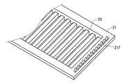
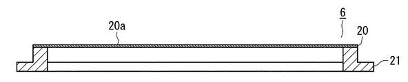
プレフィルター体6は、シート状の塵埃捕集用の濾材から成り、断面が、図2に示すように、山部20aと、谷部20bよりなる略ノコギリ刃状のフィルター20と、フィルター20の外周囲を保持する枠体21から構成されている。
The
本実施例では、フィルター20の上流側の谷部20bには、フラット面20cが形成されている。
In the present embodiment, a
枠体21は、中央に開口21aを有し、枠体21の上下方向で対向する一対の桟21bの上流側の面には、フィルター20の山部20aの裏面が気密に固着される複数の突起21cと、フィルター20のフラット面20cの裏面が気密に固着される平端部21dが設けられている。
The
以上のように、フィルター20の山部20a、フラット面20cのそれぞれを、突起21c、平端部21dに気密に固着し、更にフィルター20の左右の端部を枠体21の左右の桟21eに固着することにより、開口21aがフィルター20で完全に覆われる。
As described above, the
又、枠体21の右端の裏面には、図3(a)に示すように、ギアA21fが、上下方向に延設されている。
Further, as shown in FIG. 3 (a), a gear A21f extends in the vertical direction on the back surface of the right end of the
第1の駆動体14は、第1のモータ17と、その回転軸17aに固着され、枠体21に設けたギアA21fに噛み合う第1の駆動ギア22から構成されている。
The
除塵体12は、一端が本体1に設けた軸受部1aに回転自在に支持され、他端が第2の駆動体23に連結された軸体12aと、多数の細径の繊維などからなり、軸体12aの外周に取着されると共に、フィルター20の上流側表面に接して、フィルター20に付着した塵埃を除去するブラシ12bから構成されている。ブラシ12bの幅寸法は、フィルター20の全幅に略等しく設定されている。尚、ブラシ12bの軸体12aの外周への取着は、接着、溶着、植毛するなどの方法で固着するか、或いは、着脱自在に装着できるようにしても良い。
The
除塵体12のブラシ12bの断面形状は、図8に示すように、フィルター20の山部20aに接する谷部12cと、フィルター20の谷部20bに接する山部12dを有するノコギリ刃状に形成されている。
As shown in FIG. 8, the cross-sectional shape of the
除塵体12の軸体12aの一端に連結された第2の駆動体23を回転することにより、除塵体12を、図1において、時計方向に回転駆動して、フィルター20の上流側表面に付着した塵埃を効率よく掻き落とすことができる。
By rotating the
除塵体12で除去され落下してくる塵埃を受ける塵埃収納体13の左右方向の長さは、フィルター20の全幅にわたる長さとほぼ同一で、また、塵埃収納体13の上面には、除塵体12のブラシ12bが臨む開口部13aが形成され、塵埃収納体13内の一部には、先端がブラシ12bに食い込む櫛歯24が、ブラシ12bと平行に設けられている。
The length in the left-right direction of the
以上のように構成された本実施の形態における空気調和機の動作、作用は以下の通りである。 The operation and action of the air conditioner in the present embodiment configured as described above are as follows.
なお、本実施例における空気調和機の冷暖房運転時の動作は、従来の空気調和機のそれと同一なので、その説明を省略し、特に、プレフィルター体6の清掃運転時の動作について説明する。
In addition, since the operation | movement at the time of the air conditioning operation of the air conditioner in a present Example is the same as that of the conventional air conditioner, the description is abbreviate | omitted and especially the operation | movement at the time of the cleaning operation of the
本体1又は、本体1を遠隔操作するリモコン(図示せず)に設けたプレフィルター体クリーニングスイッチ(図示せず)を操作すると、まず最初に、第2の駆動体23の運転により除塵体12が時計方向(図1参照)に、すなわち、ブラシ12bで、フィルター20に付着した塵埃を上から下に向けて掻き落とす方向に回転する。そして、第1の駆動体14が駆動して、プレフィルター体6をゆっくりと斜め下方に移動させる。この動作により、フィルター20の下方から順に、フィルター20に付着した塵埃が掻き落とされ、その塵埃は、塵埃収納体13内に落下し、堆積していく。
When a pre-filter body cleaning switch (not shown) provided on the main body 1 or a remote controller (not shown) for remotely operating the main body 1 is operated, first, the
本実施例では、上記清掃運転のときは、ブラシ12bの外周の周速度が、プレフィルター体6の下降速度より大きくなるように設定している。これにより、プレフィルター体6に付着した塵埃を確実に除去すると共に、プレフィルター体6に余分な負荷が、すなわち、第1の駆動体14に無理な負荷が加わるのを防止している。
In this embodiment, during the cleaning operation, the peripheral speed of the outer periphery of the
上記の動作の間、ブラシ12bに塵埃が付着したまま残ることがあるが、それらは、先端がブラシ12bに食い込んだ櫛歯24により、順次取り除かれるので、塵埃の除去性能が次第に低下することが無い。
During the above operation, dust may remain attached to the
第1の駆動体14の運転により、プレフィルター体6が完全に下がりきって、プレフィルター体6の清掃が完了すると、自動的に第1の駆動体14が逆転し、プレフィルター体保持溝15にガイドされながら、プレフィルター体6が上昇し、最初の収納位置に戻る。プレフィルター体6が上昇する間に、除塵体12を清掃時と同様に、第2の駆動体23で回転させれば、プレフィルター体6の清掃をより確実に行うことができる。或いは、プレフィルター体6が上昇する間に、クラッチ機構(図示せず)などを用いて、除塵体12と第2の駆動体23との機械的連結を解除し、除塵体12が自由に回転できるようにすれば、プレフィルター体6に加わる負荷、すなわち、第1の駆動体14に加わる負荷が大幅に減るようになり、第1の駆動体14の小型化を図ることもできる。
When the
プレフィルター体6の清掃を、上記のようにして何度か行って、塵埃収納体13内が塵埃で一杯になってきたら、本体1の側面に設けた開口部(図示せず)から、塵埃収納体13を取り出して、中の塵埃を廃棄すれば良い。
When the
コスト高にはなるが、塵埃収納体13に吸引装置(図示しない)を連結して、定期的に或いは、光学的手段などを用いて、塵埃収納体13が塵埃で一杯になったことを検知したときに、前記吸引装置を運転して、外部に排出するようにすれば、手間がかからず、メンテナンスが容易な空気調和機を提供できる。
Although the cost is high, a suction device (not shown) is connected to the
また、フィルター20の上流側の谷部20bにフラット面20cを設けているので、フィルター20の谷部20bからの塵埃の除去が極めて容易になる。
Further, since the
又、上記実施例では、フィルター20のフラット面20cの裏面を、枠体21の上流側の平端部21dに固着しているので、すなわちフラット面20cが、枠体21の上流側の面より上流側に位置しているので、フィルター20の上流側の谷部20bに堆積した塵埃を除塵体12で除去する際、塵埃が、フィルター20の端部で枠体21に引っかかることがなく、塵埃処理がスムーズに出来るものである。
In the above embodiment, the back surface of the
なお、枠体21の平端部21dにフィルター20の厚み程度の段差を設け、フィルター20のフラット面20cと、枠体21の上流側の面と同一面としても同様の効果が得られることは、言うまでもない。
It is to be noted that the same effect can be obtained by providing a level difference of about the thickness of the
又、除塵体12の断面は、フィルター20の山部20aと谷部20bのそれぞれに対応するように、谷部12c、山部12dを有するノコギリ刃状に形成されているので、フィルター20で捕集された塵埃を自動的に処理する際、除塵体12が左右に変形しようとしても、それぞれの山部12d、谷部12cさらには、山部12dと谷部12cとを繋ぐ傾斜部12fにより、変形が減少されるので、確実に除塵を行うことができる。
Further, the cross section of the
さらに、プレフィルター体6を第1の駆動体14により駆動する場合も、それぞれの山部20a、谷部20bおよび山部20aと谷部20bを繋ぐ傾斜部20dがガイドレールの役目を果し、除塵体12が左右にぶれることなく、確実にプレフィルター体6の上流側表面をストレートに移動し、除塵作業を塵埃の取り残しなく、効率よく実施することが出来る。この時、除塵体12の山部12dとフィルター20の谷部20bのそれぞれのフラット面12eとフラット面20c同士が当接するため、断面が略三角状の山部と谷部が当接するのに比べて、除塵力が左右に分散されるのが少なくなり、確実に除塵できる。
Further, when the
尚、上記実施例では、プレフィルター体6の自動清掃を可能にするために、除塵体12を回転駆動する方式を採用したが、本発明は、その採用を条件とするものでは無く、使用者がプレフィルター体6を必要に応じて、空気調和機の本体1から取り外し、一般的なブラシを用いて清掃するようにした空気空気調和機においても、プレフィルター体6の谷部20bにフラット面20cが形成されているので、塵埃の除去が容易になることは言うまでもない。
In the above-described embodiment, in order to enable the
なお、上記実施例では、プレフィルター体6のフィルター20の谷部20bにフラット面20cを、それと対向する除塵体12の山部12dにフラット面12eをそれぞれ形成したが、図10に示すように、フィルター20の山部20a及び谷部20bのそれぞれにフラット面20cを、それらと対向する除塵体12側の谷部12c及び山部12dのそれぞれにフラット面12eをそれぞれ形成しても良い。
In addition, in the said Example, although the
フィルター20を上記のように構成することにより、フィルター20の強度がさらに向上し、塵埃による目詰まり状態の時でも、送風機8の吸引力に対し、変形が防止できる。また、フィルター20の山部20aにもフラット面20cが形成されているので、山部20aの塵埃も確実に除去することができる。
By configuring the
また、除塵体12の谷部12c、山部12dの両方にもフラット面12eが形成されているので、フィルター20との接触面がフラット面同士となり、垂直に当接することで、除塵力も均一に成り、その除塵効果を大幅に向上させることが出来る。
Moreover, since the
また、上記実施例では、除塵体12を、軸体12aに多数の細径の繊維などからなるブラシ12bを固着して形成したが、図11に示すように、軸体12aの外周に、それぞれ山部12d、谷部12cを形成した複数のシート状のブラシ12bを固着して構成しても良い。この場合においても、少なくとも山部12dに、フラット面12eを形成しておく、ことはいうまでもない。
Moreover, in the said Example, although the
(実施例2) (Example 2)
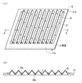
図12は、本発明の第2の実施例における空気調和機のプレフィルター体の斜視図と断面図である。尚、上記第1の実施例における空気調和機と同一部分については同じ符号を用いて説明を省略する。 FIG. 12 is a perspective view and a cross-sectional view of the prefilter body of the air conditioner according to the second embodiment of the present invention. In addition, about the same part as the air conditioner in the said 1st Example, description is abbreviate | omitted using the same code | symbol.
上記第1の実施例では、プレフィルター体6のフィルター20の谷部20bに平坦部を設けてフラット面20cを形成したが、本実施例は、図12に示すように、枠体21を成型する際に、枠体21を形成する樹脂材料がフィルター20の谷部20bに流れるように、フィルター20と一体的に成型して、谷部20bにフラット面20cを形成するようにしたものである。尚、本実施例では、フラット面20cと、枠体21の上流側の面と同一面にしているが、枠体21の上流側の面より上流側に位置しても良い。
In the first embodiment, the
上記のように構成されたプレフィルター体6によれば、フィルター20の谷部20bのフラット面20cが形成された部分では、フィルター20の細孔が樹脂で塞がれ、空気が通過しないので、その部分に塵埃が堆積し難くなり、除塵作業が一層容易になるものである。
According to the
また、フィルター20の谷部20b内でフラット面20cを形成する樹脂は、枠体21の上下の桟21bを連結するブリッジ体の役目を果たすので、枠体21の強度が向上し、フィルター20が目詰まりの状態でも、送風機8の吸引力によって容易に変形することがない。
In addition, the resin forming the
(実施例3) (Example 3)
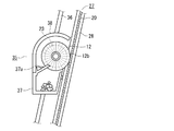
図13は、本発明の第3の実施例における空気調和機の要部断面図、プレフィルター体と除塵体の斜視図である。尚、上記実施例における空気調和機と同一部分については同じ符号を用いて説明を省略する。 FIG. 13: is principal part sectional drawing of the air conditioner in the 3rd Example of this invention, and is a perspective view of a pre filter body and a dust removal body. In addition, about the same part as the air conditioner in the said Example, description is abbreviate | omitted using the same code | symbol.
上記第1の実施例では、除塵体の位置を固定し、プレフィルター体を上下方向に移動させることで、プレフィルター体の全域を清掃するようにしたが、本実施例は、プレフィルター体を固定し、除塵体を上下動させて、プレフィルター体の全域を清掃することが出来るようにするものである。 In the first embodiment, the entire position of the prefilter body is cleaned by fixing the position of the dust removing body and moving the prefilter body in the vertical direction. The dust filter is fixed and moved up and down to clean the entire prefilter body.
図13において、本実施例における空気調和機のプレフィルター体27は、枠体28とその枠体28に気密に、且つ山部20aが上下方向になるようにして固着されたフィルター20から構成され、その枠体28の下部に、上面が開口しフィルター20から落下する塵埃を受け、収納する塵埃収納体29が着脱自在に取り付けられている。言うまでも無いが、塵埃収納体29を枠体28の所定の部分に取り付けたとき、塵埃収納体29が、フィルター20の真下に位置するようになっている。
In FIG. 13, the
30は、フィルター20の上流側表面に付着した塵埃を除去する除塵体で、多数の細径の繊維あるいはシート状の部材からなりフィルター20の山部20a、谷部20bのそれぞれに摺接する谷部31a、山部31bを有するブラシ31と、ブラシ31を保持するブラシ保持部材32から構成されている。
30 is a dust remover that removes dust adhering to the upstream surface of the
空気調和機の本体1には、ブラシ保持部材32の両端を上下方向にガイドするガイド溝33が形成されている。本体1には、特に図示しないが、ブラシ保持部材32を、図13に示すように、ブラシ31の谷部31a、山部31bを、フィルター20の山部20a、谷部20bに摺接させた状態で上下に移動させる第3の駆動体が設けられている。
In the main body 1 of the air conditioner, guide
以上のように構成された本実施例における空気調和機のプレフィルター体27の清掃動作は以下の通りである。
The cleaning operation of the
通常は、除塵体30は、そのブラシ31が、フィルター20の上端に接する位置(以下「上死点」という)で支持されている。そして、プレフィルター体27の清掃を行うために第3の駆動体を運転すると、除塵体30が下降し、その間に、フィルター20に付着した塵埃が、ブラシ31で除去され、下方に落下して、塵埃収納体29に堆積していく。
Normally, the
そして、除塵体30のブラシ31がフィルター20の下端に接する位置(図13(a)で点線で示された位置。以下「下死点」という)に達すると、次の清掃に備えるため、自動的に第3の駆動体が逆駆動し、除塵体30を元の上死点まで移動させる。
When the
塵埃収納体29に堆積した塵埃を廃棄するときは、塵埃収納体29に設けた取っ手29aを掴んで、塵埃収納体29を枠体28から取り外して簡単に行うことができる。
When discarding the dust accumulated in the
以上のように、本実施例によれば、プレフィルター体27を固定し、除塵体30を上下動させるようにしているので、プレフィルター体27の清掃時に、プレフィルター体27が、本体1の底部から飛び出すことが無く、安価で、意匠的にも優れた空気調和機を提供することが出来るものである。
As described above, according to the present embodiment, since the
尚、上記実施例では、塵埃収納体29を枠体28に着脱自在に設けたが、空気調和機の本体1に着脱自在に設けても良い。
In addition, in the said Example, although the
また、本実施例では、プレフィルター体27の下部に塵埃収納体29を取り付けたが、プレフィルター体27のフィルター20を、横向きに、すなわち山部20a、谷部20bの稜線が水平になるように設け、更に除塵体30を左右方向に移動するように設けた場合は、塵埃収納体29を枠体28の左右のいずれかの端部に設けると良い。
Further, in this embodiment, the
(実施例4) (Example 4)
図14は、本発明の第4の実施例における空気調和機の要部断面図である。尚、上記実施例における空気調和機と同一部分については同じ符号を用いて説明を省略する。 FIG. 14 is a cross-sectional view of an essential part of an air conditioner according to a fourth embodiment of the present invention. In addition, about the same part as the air conditioner in the said Example, description is abbreviate | omitted using the same code | symbol.
本実施例は、プレフィルター体を本体に固定し、プレフィルター体の清掃時に、除塵体を回転させながら、それをプレフィルター体の上流側の表面に沿って上下動させるようにしたものである。 In this embodiment, the prefilter body is fixed to the main body, and when the prefilter body is cleaned, it is moved up and down along the upstream surface of the prefilter body while rotating the dust removing body. .
図14において、本実施例における空気調和機は、上記第3の実施例におけるプレフィルター体27を備え、そのプレフィルター体27の上流側には、除塵体ユニット35が配されている。除塵体ユニット35は、本体1に設けたガイドレール36に沿って、図示しない第4の駆動体により、プレフィルター体27に平行に、且つ上下方向に移動可能に設けられている。
In FIG. 14, the air conditioner in the present embodiment includes the
除塵体ユニット35は、上記第1の実施例で述べた除塵体12と、除塵体12を時計方向に回転駆動する第2の駆動体23と、除塵体12を覆うカバー体38と、除塵体12のブラシ12bによってフィルター20から除去された塵埃を収納すると共に、カバー体38に着脱自在に取着される塵埃収納体37から構成されている。37aは、塵埃収納体37の一部に形成され、ブラシ12bに付着した塵埃を梳く梳き歯である。その他の構成は、上記第3の実施例に記載された空気調和機と同一である。
The
以上のように構成された本実施例における空気調和機のプレフィルター体27の清掃動作は、以下の通りである。
The cleaning operation of the
通常、除塵体ユニット35は、内設された除塵体12のブラシ12bがフィルター20の上端に接する位置(以下「上死点」という)で保持されている。そして、プレフィルター体27の清掃を行うために、第2の駆動体23及び第4の駆動体(図示せず)を運転すると、除塵体12が時計方向に回転しながら、除塵体ユニット35が徐々に下降していく。その間に、フィルター20に付着した塵埃が、ブラシ12bで掻き取られ、塵埃収納体37の中に落下し、次第に堆積していく。ブラシ12bに付着して自然落下しない塵埃は、梳き歯37aにより梳かれて、塵埃収納体37内に落下する。
Usually, the
そして、除塵体ユニット35が、ブラシ12bがフィルター20の下端に接する位置(以下「下死点」という)に達すると、次の清掃に備えるため、自動的に第4の駆動体が逆駆動し、除塵体ユニット35を元の上死点まで移動させた後、自動的に停止する。
When the
塵埃収納体35が塵埃で一杯になったら、塵埃収納体35をカバー体38から取り外すことにより、簡単に行うことができる。
When the
以上のように、本実施例によれば、プレフィルター体27を固定し、除塵体ユニット35を上下動させるようにしているので、プレフィルター体27の清掃時に、プレフィルター体27が、本体1の底部から飛び出すことが無く、意匠的に優れた空気調和機を提供することが出来るものである。
As described above, according to the present embodiment, since the
以上のように、本発明にかかる空気調和機は、断面形状が山部と谷部より成る略ノコギリ刃状に形成したプレフィルター体に堆積した塵埃の除去が極めて容易なもので、空気調和機に限らず、断面略ノコギリ刃状に形成されたフィルターを有する各種機器に応用できる。 As described above, the air conditioner according to the present invention is extremely easy to remove dust accumulated on the prefilter body having a substantially saw-toothed cross-sectional shape composed of a peak portion and a valley portion. The present invention is not limited to this, and can be applied to various devices having a filter formed in a substantially saw blade shape in cross section.
1 本体
2 吸込み口
4 排気口
5 通過回路
6、27 プレフィルター体
7 室内熱交換器
8 送風機
12、30 除塵体
13、29、37 除塵収納体
14 第1の駆動体(駆動体)
20 フィルター
20a 山部
20b 谷部
20c フラット面
21、28 枠体
23 第2の駆動体
DESCRIPTION OF SYMBOLS 1 Main body 2
12, 30
20
Claims (8)
Priority Applications (1)
| Application Number | Priority Date | Filing Date | Title |
|---|---|---|---|
| JP2008112153A JP2009264618A (en) | 2008-04-23 | 2008-04-23 | Air conditioner |
Applications Claiming Priority (1)
| Application Number | Priority Date | Filing Date | Title |
|---|---|---|---|
| JP2008112153A JP2009264618A (en) | 2008-04-23 | 2008-04-23 | Air conditioner |
Publications (2)
| Publication Number | Publication Date |
|---|---|
| JP2009264618A true JP2009264618A (en) | 2009-11-12 |
| JP2009264618A5 JP2009264618A5 (en) | 2011-06-16 |
Family
ID=41390684
Family Applications (1)
| Application Number | Title | Priority Date | Filing Date |
|---|---|---|---|
| JP2008112153A Pending JP2009264618A (en) | 2008-04-23 | 2008-04-23 | Air conditioner |
Country Status (1)
| Country | Link |
|---|---|
| JP (1) | JP2009264618A (en) |
Cited By (1)
| Publication number | Priority date | Publication date | Assignee | Title |
|---|---|---|---|---|
| JP2015079769A (en) * | 2010-05-13 | 2015-04-23 | ゴア エンタープライズ ホールディングス,インコーポレイティド | Improved vent device |
Citations (9)
| Publication number | Priority date | Publication date | Assignee | Title |
|---|---|---|---|---|
| JPH0833823A (en) * | 1994-07-22 | 1996-02-06 | Nittetsu Mining Co Ltd | Reinforced filter element |
| JPH08303803A (en) * | 1995-05-08 | 1996-11-22 | Daikin Ind Ltd | Air conditioner |
| JPH09133398A (en) * | 1995-11-07 | 1997-05-20 | Matsushita Refrig Co Ltd | Air conditioner |
| JPH11129695A (en) * | 1997-10-29 | 1999-05-18 | Shin Fukui | Motor operated blackboard eraser |
| JP2005034213A (en) * | 2003-07-16 | 2005-02-10 | Matsushita Electric Ind Co Ltd | Electric vacuum cleaner |
| JP2005177575A (en) * | 2003-12-17 | 2005-07-07 | Toshiba Kyaria Kk | Air filter |
| JP2005261518A (en) * | 2004-03-17 | 2005-09-29 | Toshiba Tec Corp | Vacuum cleaner |
| JP2007263412A (en) * | 2006-03-27 | 2007-10-11 | Kowa Co Ltd | Cleaning device of air conditioner, and air conditioner |
| JP2008002772A (en) * | 2006-06-23 | 2008-01-10 | Kowa Co Ltd | Cleaning body for air conditioner, spinning rotor, and air conditioner |
-
2008
- 2008-04-23 JP JP2008112153A patent/JP2009264618A/en active Pending
Patent Citations (9)
| Publication number | Priority date | Publication date | Assignee | Title |
|---|---|---|---|---|
| JPH0833823A (en) * | 1994-07-22 | 1996-02-06 | Nittetsu Mining Co Ltd | Reinforced filter element |
| JPH08303803A (en) * | 1995-05-08 | 1996-11-22 | Daikin Ind Ltd | Air conditioner |
| JPH09133398A (en) * | 1995-11-07 | 1997-05-20 | Matsushita Refrig Co Ltd | Air conditioner |
| JPH11129695A (en) * | 1997-10-29 | 1999-05-18 | Shin Fukui | Motor operated blackboard eraser |
| JP2005034213A (en) * | 2003-07-16 | 2005-02-10 | Matsushita Electric Ind Co Ltd | Electric vacuum cleaner |
| JP2005177575A (en) * | 2003-12-17 | 2005-07-07 | Toshiba Kyaria Kk | Air filter |
| JP2005261518A (en) * | 2004-03-17 | 2005-09-29 | Toshiba Tec Corp | Vacuum cleaner |
| JP2007263412A (en) * | 2006-03-27 | 2007-10-11 | Kowa Co Ltd | Cleaning device of air conditioner, and air conditioner |
| JP2008002772A (en) * | 2006-06-23 | 2008-01-10 | Kowa Co Ltd | Cleaning body for air conditioner, spinning rotor, and air conditioner |
Cited By (1)
| Publication number | Priority date | Publication date | Assignee | Title |
|---|---|---|---|---|
| JP2015079769A (en) * | 2010-05-13 | 2015-04-23 | ゴア エンタープライズ ホールディングス,インコーポレイティド | Improved vent device |
Similar Documents
| Publication | Publication Date | Title |
|---|---|---|
| JP4757730B2 (en) | Air conditioner | |
| JP5530944B2 (en) | Air conditioner | |
| JP4050774B2 (en) | Air conditioner | |
| CN1475706A (en) | Air conditioner | |
| JP2007263412A (en) | Cleaning device of air conditioner, and air conditioner | |
| JP2019152417A (en) | Filter cleaning device of air conditioner | |
| JP5424185B2 (en) | Air conditioner | |
| JP4428333B2 (en) | Air conditioner | |
| JP3918789B2 (en) | Air conditioner | |
| JP2008057846A (en) | Air conditioner | |
| JP2008246463A (en) | Air conditioner | |
| JP2007101116A5 (en) | ||
| JP2007240114A (en) | Cleaning device for air conditioner, and air conditioner | |
| JP2012032080A (en) | Air filter, cleaning unit for the air filter, and air conditioner using them | |
| JP6138206B2 (en) | Air cleaner | |
| JP2010002070A (en) | Air conditioner | |
| JP2009264618A (en) | Air conditioner | |
| JP2009180465A (en) | Air conditioner | |
| JP2006289235A (en) | Air cleaner | |
| JP2008002772A (en) | Cleaning body for air conditioner, spinning rotor, and air conditioner | |
| JP2012032137A (en) | Air conditioner | |
| JP6464019B2 (en) | Air cleaner | |
| JP2009257735A (en) | Air conditioner | |
| JP4665604B2 (en) | Air conditioner | |
| JP2007232229A (en) | Cleaning device of air conditioning device, and air conditioning device |
Legal Events
| Date | Code | Title | Description |
|---|---|---|---|
| A521 | Request for written amendment filed |
Free format text: JAPANESE INTERMEDIATE CODE: A523 Effective date: 20110421 |
|
| A621 | Written request for application examination |
Free format text: JAPANESE INTERMEDIATE CODE: A621 Effective date: 20110421 |
|
| RD02 | Notification of acceptance of power of attorney |
Free format text: JAPANESE INTERMEDIATE CODE: A7422 Effective date: 20110421 |
|
| A977 | Report on retrieval |
Free format text: JAPANESE INTERMEDIATE CODE: A971007 Effective date: 20120829 |
|
| A131 | Notification of reasons for refusal |
Free format text: JAPANESE INTERMEDIATE CODE: A131 Effective date: 20120907 |
|
| A02 | Decision of refusal |
Free format text: JAPANESE INTERMEDIATE CODE: A02 Effective date: 20130108 |