JP2009255410A - Method of forming half tone dot image, method of forming threshold value matrix, threshold value matrix, method of manufacturing printing plate and printing plate - Google Patents
Method of forming half tone dot image, method of forming threshold value matrix, threshold value matrix, method of manufacturing printing plate and printing plate Download PDFInfo
- Publication number
- JP2009255410A JP2009255410A JP2008107584A JP2008107584A JP2009255410A JP 2009255410 A JP2009255410 A JP 2009255410A JP 2008107584 A JP2008107584 A JP 2008107584A JP 2008107584 A JP2008107584 A JP 2008107584A JP 2009255410 A JP2009255410 A JP 2009255410A
- Authority
- JP
- Japan
- Prior art keywords
- cluster
- halftone
- minimum
- image
- pixels
- Prior art date
- Legal status (The legal status is an assumption and is not a legal conclusion. Google has not performed a legal analysis and makes no representation as to the accuracy of the status listed.)
- Pending
Links
Images


Classifications
-
- H—ELECTRICITY
- H04—ELECTRIC COMMUNICATION TECHNIQUE
- H04N—PICTORIAL COMMUNICATION, e.g. TELEVISION
- H04N1/00—Scanning, transmission or reproduction of documents or the like, e.g. facsimile transmission; Details thereof
- H04N1/40—Picture signal circuits
- H04N1/405—Halftoning, i.e. converting the picture signal of a continuous-tone original into a corresponding signal showing only two levels
- H04N1/4055—Halftoning, i.e. converting the picture signal of a continuous-tone original into a corresponding signal showing only two levels producing a clustered dots or a size modulated halftone pattern
- H04N1/4057—Halftoning, i.e. converting the picture signal of a continuous-tone original into a corresponding signal showing only two levels producing a clustered dots or a size modulated halftone pattern the pattern being a mixture of differently sized sub-patterns, e.g. spots having only a few different diameters
Abstract
Description
本発明は、凸版印刷用の刷版に形成される網点画像を生成する網点画像生成方法、並びに、網点画像を生成する際に、網点画像により表現される多階調の元画像と比較される閾値マトリクスおよびその生成方法に関し、また、凸版印刷用の刷版およびその製造方法にも関連する。 The present invention relates to a halftone image generating method for generating a halftone image formed on a printing plate for letterpress printing, and a multi-tone original image represented by a halftone image when generating a halftone image. And a method for producing the threshold matrix, and also relates to a printing plate for letterpress printing and a method for producing the same.
従来より、商業印刷では、フレキソ印刷やレタープレス印刷等の凸版印刷が行われており、CTP(computer to plate)等の技術を利用して凸版印刷用の刷版の製造が行われている。凸版印刷用の刷版の製造では、例えば、感光性樹脂層上に積層されたマスク層に対してCTPによりレーザ光が照射され、多階調(すなわち、連続階調)の元画像から生成された印刷用の画像である網点画像に対応する開口がマスク層に形成される。そして、マスク層の開口を介して感光性樹脂層に紫外線を照射して感光性樹脂層の表面近傍の一部を硬化させた後、マスク層および感光性樹脂層の表面の非硬化部を除去する現像工程等が行われることにより、表面に網点画像に対応する凸部を有する刷版が形成される。 Conventionally, in commercial printing, letterpress printing such as flexographic printing and letterpress printing has been performed, and printing plates for letterpress printing have been manufactured using techniques such as CTP (computer to plate). In the manufacture of a printing plate for letterpress printing, for example, a mask layer laminated on a photosensitive resin layer is irradiated with laser light by CTP, and is generated from an original image having multiple gradations (that is, continuous gradation). An opening corresponding to a halftone dot image which is an image for printing is formed in the mask layer. Then, after irradiating the photosensitive resin layer with ultraviolet rays through the opening of the mask layer to cure a portion near the surface of the photosensitive resin layer, the mask layer and the non-cured portion of the surface of the photosensitive resin layer are removed. By performing the developing step or the like, a printing plate having a convex portion corresponding to the halftone dot image is formed on the surface.
一方、多階調の元画像から印刷用の網点画像を生成する際には、例えば、規則的に配置されたドット(正確には互いに接合したドット(または画素)の集合であるクラスタ)の大きさを変えることにより階調表現が実現されるAM(Amplitude Modulated)スクリーニングが用いられる。実際には、複数の要素が行方向および列方向に配列されるとともに各要素に閾値が付与された閾値マトリクスが予め生成されて準備され、元画像と閾値マトリクスとを比較することにより印刷に用いられる網点画像が生成される。 On the other hand, when generating a halftone image for printing from a multi-tone original image, for example, regularly arranged dots (more precisely, a cluster that is a set of dots (or pixels) joined to each other). AM (Amplitude Modulated) screening in which gradation expression is realized by changing the size is used. In practice, a threshold matrix in which a plurality of elements are arranged in the row direction and the column direction and a threshold value is assigned to each element is generated and prepared in advance, and is used for printing by comparing the original image and the threshold matrix. A halftone dot image is generated.
凸版印刷では、最小網点サイズが小さい場合や網点の線数が小さい(すなわち、ピッチが大きい)場合、刷版の網点面積率が小さい(すなわち、網点の密度が低い)ハイライト領域において、刷版のレリーフが細くまたは小さくなってしまい、レリーフの強度不足により刷版製造時の現像工程等においてレリーフが折れ曲がる形成不良が生じ、印刷画像にて元画像を適切に表現する印刷再現性が低下してしまう。また、印刷時の圧力によりレリーフが折れ曲がって印刷再現性が低下する場合もある。 In letterpress printing, when the minimum halftone dot size is small or the number of halftone dot lines is small (that is, the pitch is large), the halftone dot area ratio of the printing plate is small (that is, the halftone dot density is low). In printing, the relief of the printing plate becomes thin or small, and due to insufficient strength of the relief, there is a formation defect in which the relief is bent in the development process, etc. during printing plate production, and the print reproducibility that properly represents the original image in the printed image Will fall. In addition, the relief may be bent by the pressure during printing, and the print reproducibility may be reduced.
ハイライト領域においてレリーフが細くなるという現象に対しては、例えば、非特許文献1のFig6.24に示される閾値マトリクスを用いて最小網点サイズを最小分解能の画素サイズよりも大きくすることにより改善することが可能である。
The phenomenon that the relief becomes thin in the highlight region can be improved by, for example, using the threshold matrix shown in FIG. 6.24 of
特許文献1ないし4では、レリーフの強度を向上する方法として、レリーフをサポートするためのドットをレリーフから離間した位置に形成する技術が開示されている。これらのサポート用のドットはいずれも、印刷用のレリーフに比べて低い凸部とされており、印刷対象には含まれない。また、特許文献5では、ハイライト領域から中間階調の領域(すなわち、ハイライト領域と網点面積率が大きいシャドー領域との間の領域)において各網点の形状を十字型とする技術が開示されている。
ところで、非特許文献1のように最小網点サイズを大きくすると、ハイライト領域において所望の網点面積率を実現するために網点の個数を減らすことになり、網点のピッチが大きくなってレリーフの強度が低下し、その結果、印刷再現性が低下してしまう。
By the way, when the minimum halftone dot size is increased as in Non-Patent
一方、特許文献1ないし4では、サポート用のドットは印刷対象に含まれないものとされているが、刷版形成時にサポート用のドットとなる部位に対して照射される光の強度が所望の強度より大きい場合等、サポート用のドットが印刷用のレリーフと同等の高さとなってしまい、本来印刷されるべきではないサポート用のドットまで印刷されてしまう(いわゆる、地汚れが生じてしまう)おそれがある。これとは反対に、刷版形成時にサポート用のドットとなる部位に対して照射される光の強度が所望の強度より小さい場合には、サポート用のドットが必要以上に小さくなってしまい、レリーフが十分にサポートされず、レリーフの強度が低下してしまう可能性がある。いずれの場合も、印刷再現性は低下することとなる。
On the other hand, in
特許文献5では、中間階調の領域においても網点形状が十字型とされるため、網点の周囲長が大きくなってしまう。このため、印刷時に印刷圧の僅かな変動により、印刷されるドットが太くなったり細くなってしまい、印刷再現性が低下してしまう。
In
本発明は、上記課題に鑑みなされたものであり、凸版印刷用の刷版に形成される網点画像において最小網点に対応するレリーフの強度を向上することにより、網点画像の印刷再現性を向上することを目的としている。 The present invention has been made in view of the above problems, and by improving the strength of the relief corresponding to the minimum halftone dot in the halftone dot image formed on the printing plate for letterpress printing, the print reproducibility of the halftone dot image is achieved. It aims to improve.
請求項1に記載の発明は、凸版印刷用の刷版に形成される網点画像を生成する網点画像生成方法であって、網点が存在しない最も低い階調レベルに近いモード切替階調レベルが予め設定されており、多階調の元画像において前記モード切替階調レベル以下の階調レベルの領域に対応する網点画像生成空間内の領域において、前記元画像における階調レベルが高いほど高い密度となるように3以上の画素からなる最小網点を予め定められた複数の網点中心位置のいずれかに形成する工程と、前記元画像において前記モード切替階調レベルよりも高い階調レベルの領域に対応する前記網点画像生成空間内の領域において、前記元画像における階調レベルが高いほど前記最小網点から成長した網点を各網点中心位置に形成する工程とを備え、前記最小網点が、2以上の画素からなる矩形状のメインクラスタと、前記メインクラスタの周囲に配置され、前記メインクラスタの画素数よりも少ない数の画素からなるサブクラスタとを備え、前記サブクラスタが、一の画素、または、前記メインクラスタからおよそ離れる方向へと配列された複数の画素であり、前記メインクラスタと頂点のみにおいて、または、前記メインクラスタの辺よりも短い辺のみにおいて前記メインクラスタと接する。
The invention according to
請求項2に記載の発明は、請求項1に記載の網点画像生成方法であって、生成される網点画像の解像度をA、前記解像度に対応する単位長さ当たりの網点の線数をB、前記最小網点の画素数をC、前記最も低い階調レベルから最も高い階調レベルまでの階調数をGとして、前記モード切替階調レベルが、Gの100×C/((A/B)×(A/B))%である。
The invention according to
請求項3に記載の発明は、請求項1または2に記載の網点画像生成方法であって、前記メインクラスタの一対の辺に平行な第1の方向において前記サブクラスタが前記メインクラスタよりも小さく、かつ、前記第1の方向に垂直な第2の方向において前記サブクラスタが前記メインクラスタよりも小さい。
The invention according to
請求項4に記載の発明は、請求項1ないし3のいずれかに記載の網点画像生成方法であって、前記サブクラスタが、1列に配列された複数の画素である。 A fourth aspect of the present invention is the halftone image generating method according to any one of the first to third aspects, wherein the sub-cluster is a plurality of pixels arranged in one column.
請求項5に記載の発明は、請求項1ないし4のいずれかに記載の網点画像生成方法であって、前記最小網点が、前記サブクラスタと同形状であり、前記サブクラスタと共に前記メインクラスタの周囲に放射状に配置された3つのサブクラスタをさらに備える。 A fifth aspect of the present invention is the halftone image generation method according to any one of the first to fourth aspects, wherein the minimum halftone dot has the same shape as the sub-cluster, and the main cluster together with the sub-cluster. It further comprises three sub-clusters arranged radially around the cluster.
請求項6に記載の発明は、凸版印刷用の刷版に形成される網点画像を生成する際に、前記網点画像により表現される多階調の元画像と比較される閾値マトリクスを生成する閾値マトリクス生成方法であって、a)3以上の画素からなる複数の最小クラスタを、互いにおよそ均一に離れた状態にて、前記閾値マトリクスが生成されるマトリクス空間に設定する工程と、b)一の最小クラスタの全画素に同一の閾値を付与し、次の最小クラスタが有る場合に、前記次の最小クラスタの全画素に、前記一の最小クラスタに付与された閾値よりも最小クラスタの画素数だけ大きい閾値を付与する工程と、c)前記複数の最小クラスタに対して前記b)工程を順次繰り返す工程と、d)元画像における階調レベルの増加に伴って網点画像において前記複数の最小クラスタに対応する複数の最小網点から網点領域が成長するように、前記マトリクス空間の前記複数の最小クラスタを除く領域に閾値を設定する工程とを備え、前記最小クラスタが、2以上の画素からなる矩形状のメインクラスタと、前記メインクラスタの周囲に配置され、前記メインクラスタの画素数よりも少ない数の画素からなるサブクラスタとを備え、前記サブクラスタが、一の画素、または、前記メインクラスタからおよそ離れる方向へと配列された複数の画素であり、前記メインクラスタと頂点のみにおいて、または、前記メインクラスタの辺よりも短い辺のみにおいて前記メインクラスタと接する。 The invention according to claim 6 generates a threshold matrix to be compared with the multi-tone original image represented by the halftone image when generating the halftone image formed on the printing plate for letterpress printing. A) a threshold matrix generation method, wherein a) a plurality of minimum clusters composed of three or more pixels are set in a matrix space in which the threshold matrix is generated in a state of being approximately uniformly spaced from each other; b) The same threshold value is assigned to all pixels of one minimum cluster, and when there is a next minimum cluster, all the pixels of the next minimum cluster have pixels of the minimum cluster than the threshold value assigned to the one minimum cluster. C) a step of sequentially repeating the step b) with respect to the plurality of minimum clusters, and d) the duplication in the halftone image with an increase in the gradation level in the original image. And setting a threshold value in a region excluding the plurality of minimum clusters in the matrix space so that a halftone dot region grows from a plurality of minimum halftone dots corresponding to the minimum cluster of A main cluster having a rectangular shape, and a sub-cluster arranged around the main cluster and having a smaller number of pixels than the number of pixels of the main cluster, the sub-cluster being one pixel, or A plurality of pixels arranged in a direction approximately away from the main cluster, and is in contact with the main cluster only at the main cluster and the vertex or only at a side shorter than the side of the main cluster.
請求項7に記載の発明は、請求項6に記載の閾値マトリクス生成方法であって、前記メインクラスタの一対の辺に平行な第1の方向において前記サブクラスタが前記メインクラスタよりも小さく、かつ、前記第1の方向に垂直な第2の方向において前記サブクラスタが前記メインクラスタよりも小さい。 The invention according to claim 7 is the threshold matrix generation method according to claim 6, wherein the sub-cluster is smaller than the main cluster in a first direction parallel to a pair of sides of the main cluster, and The sub-cluster is smaller than the main cluster in a second direction perpendicular to the first direction.
請求項8に記載の発明は、請求項6または7に記載の閾値マトリクス生成方法であって、前記サブクラスタが、1列に配列された複数の画素である。 The invention according to claim 8 is the threshold value matrix generation method according to claim 6 or 7, wherein the sub-cluster is a plurality of pixels arranged in one column.
請求項9に記載の発明は、請求項6ないし8のいずれかに記載の閾値マトリクス生成方法であって、前記最小クラスタが、前記サブクラスタと同形状であって前記サブクラスタと共に前記メインクラスタの周囲に放射状に配置された3つのサブクラスタをさらに備える。 The invention according to claim 9 is the threshold value matrix generation method according to any one of claims 6 to 8, wherein the minimum cluster has the same shape as the sub-cluster, and the main cluster together with the sub-cluster. It further comprises three sub-clusters arranged radially around the periphery.
請求項10に記載の発明は、凸版印刷用の刷版に形成される網点画像を生成する際に、前記網点画像により表現される多階調の元画像と比較される閾値マトリクスであって、請求項6ないし9のいずれかに記載の閾値マトリクス生成方法にて生成されたものである。 The invention according to claim 10 is a threshold matrix that is compared with a multi-tone original image expressed by the halftone image when generating a halftone image formed on a printing plate for letterpress printing. Thus, the threshold value matrix generation method according to any one of claims 6 to 9 is used.
請求項11に記載の発明は、凸版印刷用の刷版に網点画像を形成する刷版製造方法であって、感光性樹脂層上にマスク層が積層された版材の前記マスク層に、請求項1ないし5のいずれかに記載の網点画像生成方法により生成された網点画像に対応する開口を形成する工程と、前記マスク層の前記開口を介して前記感光性樹脂層に光を照射して前記感光性樹脂層の前記マスク層と対向する部位の一部を硬化部とする工程と、前記マスク層、および、前記感光性樹脂層の前記マスク層と対向する前記部位のうち前記硬化部を除く部位を除去することにより、前記網点画像に対応する凸部を有する刷版を形成する工程とを備える。
The invention according to
請求項12に記載の発明は、凸版印刷用の刷版であって、請求項11に記載の刷版製造方法により網点画像が形成されたものである。
The invention described in
本発明では、凸版印刷用の刷版に形成される網点画像において最小網点に対応するレリーフの強度を向上することができ、その結果、網点画像の印刷再現性を向上することができる。 In the present invention, the strength of the relief corresponding to the minimum halftone dot in the halftone image formed on the printing plate for letterpress printing can be improved, and as a result, the print reproducibility of the halftone image can be improved. .
また、請求項6ないし9の発明では、最小網点に対応するレリーフの強度が向上された網点画像を容易に形成可能な閾値マトリクスを得ることができ、請求項10の発明に係る閾値マトリクスを利用することにより、最小網点に対応するレリーフの強度が向上された網点画像を容易に形成することができる。 Further, in the inventions of claims 6 to 9, a threshold value matrix capable of easily forming a halftone dot image having an improved relief intensity corresponding to the minimum halftone dot can be obtained, and the threshold value matrix according to the invention of claim 10 is provided. By using this, it is possible to easily form a halftone dot image in which the strength of the relief corresponding to the minimum halftone dot is improved.
請求項11の発明では、最小網点に対応するレリーフの強度が向上された網点画像を有する刷版を容易に得ることができ、請求項12の発明に係る刷版を利用することにより、網点画像の印刷再現性を向上することができる。
In the invention of
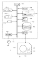
図1は本発明の一の実施の形態に係る画像記録システム1の構成を示す図である。画像記録システム1は、コンピュータ11および画像記録装置12を備え、画像記録装置12はコンピュータ11からの信号を受けて凸版印刷用の刷版となる版材に複数チャンネルのレーザ等からの光ビームを用いて網点を記録する。
FIG. 1 is a diagram showing a configuration of an
コンピュータ11は、各種演算処理を行うCPU101、基本プログラムを記憶するROM102、および、各種情報を記憶するRAM103をバスラインに接続した一般的なコンピュータシステムの構成となっている。バスラインにはさらに、網点化される多階調の画像(以下、「元画像」という。)のデータを記憶する画像メモリ104、情報記憶を行う固定ディスク105、各種情報の表示を行うディスプレイ106、操作者からの入力を受け付けるキーボード107aおよびマウス107b、光ディスク、磁気ディスク、光磁気ディスク等のコンピュータ読み取り可能な記録媒体91から情報の読み取りを行う読取装置108、並びに、画像記録装置12と通信を行う通信部109が、適宜、インターフェイス(I/F)を介する等して接続される。
The
画像記録装置12は、紫外線硬化性(すなわち、紫外線の照射により不溶化するタイプ)の感光性樹脂層上にマスク層が積層された版材80をマスク層を外側にしてその側面に保持するドラム121、版材80に向けて複数チャンネルの変調された光ビームを出射する描画ヘッド122、描画ヘッド122に送られる網点画像の信号を生成する信号生成回路123、その他、ドラム121を回転して描画ヘッド122を版材80に対して走査したり、描画ヘッド122をドラム121の回転軸に沿って移動する駆動機構等を備える。以下の説明における「画素」とは、画像記録装置12の記録(描画ともいう。)の1単位をいい、1つの光ビームによる1スポットに相当する。
The
コンピュータ11には、事前に読取装置108を介して記録媒体91からプログラム92が読み出され、固定ディスク105に記憶される。そして、プログラム92がRAM103にコピーされるとともにCPU101がRAM103内のプログラムに従って演算処理を実行することにより(すなわち、コンピュータがプログラムを実行することにより)、網点形成用の後述の閾値マトリクス(SPM(Screen Pattern Memory)データとも呼ばれる。)710が生成される。閾値マトリクス710および画像メモリ104に記憶されている多階調の元画像のデータは、通信部109を介して画像記録装置12に転送され、画像記録装置12の信号生成回路123により、元画像を表現する網点画像の信号(網点画像データ)が生成される。そして、描画ヘッド122を版材80に対して走査しつつ網点画像データに基づいて版材80のマスク層に光ビームが照射されることにより、版材80のマスク層に網点画像に対応する開口が形成される。換言すれば、光ビームの照射によるアブレーション描画により、マスク層に網点画像が描画される。
The
図2は、画像記録装置12の信号生成回路123の構成要素および記録機構120を示すブロック図である。記録機構120は図1中のドラム121、描画ヘッド122、これらを駆動する機構や制御する回路等に対応する。
FIG. 2 is a block diagram showing the components of the
信号生成回路123は、多階調の元画像のデータを記憶する画像メモリ21、元画像の副走査アドレス(Xアドレス)および主走査アドレス(Yアドレス)をそれぞれ発生するXアドレス発生器22aおよびYアドレス発生器22b、コンピュータ11にて生成された閾値マトリクス710を記憶するSPM(Screen Pattern Memory)23、閾値マトリクス710の副走査アドレス(xアドレス)および主走査アドレス(yアドレス)をそれぞれ発生するxアドレス発生器24aおよびyアドレス発生器24b、並びに、比較器(コンパレータ)25を備える。
The
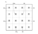
元画像の網点化に際して(すなわち、元画像を表現する網点画像を生成する際に)、図3に示すように元画像70を同一の大きさの多数の領域に分割して網点化の単位となる繰り返し領域71が設定される。SPM23は一の繰り返し領域71に相当する記憶領域であるマトリクス空間(マトリクス領域)を有し、マトリクス空間の各アドレス(すなわち、繰り返し領域71の各画素に対応するマトリクス空間の座標であり、以下の説明では、マトリクス空間の画素ともいう。)に閾値が設定されることにより閾値マトリクス710が生成される。
When the original image is halftone (that is, when a halftone image representing the original image is generated), as shown in FIG. 3, the
そして、概念的には元画像70の各繰り返し領域71と閾値マトリクス710とを重ね合わせ、繰り返し領域71の各画素の階調レベルと閾値マトリクス710の対応する閾値とが比較されることにより、網点記録媒体である版材80上のその画素の位置に描画を行うか否か(すなわち、レーザ光を照射するか否か)が決定される。したがって、仮に元画像70の階調レベルが一様である場合は、閾値マトリクス710においてその階調レベルよりも小さな閾値が設定されているアドレスの画素に描画が行われ、巨視的には一様な網点が生成されることとなる。実際には元画像70は濃淡(すなわち、様々な階調レベルの部位)を有するため、繰り返し領域71内において元画像70の濃淡に応じて網点の状態が変化することとなる。
Conceptually, each
図4.Aおよび図4.Bは画像記録システム1の動作の流れを示す図である。以下では、規則的に配置された網点の大きさを変更することにより階調表現が実現されるAM(Amplitude Modulated)スクリーニングを利用して網点画像が生成されるものとして説明する。本実施の形態では、生成される網点画像の解像度Aは2400(dpi)、解像度Aに対応する単位長さ(1インチ)当たりの網点の線数Bは150であり、図5に示すように、網点が形成される領域の単位となる網点セル712の形状は正方形である。
FIG. A and FIG. B is a diagram showing the flow of operation of the
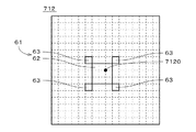
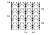
図6に示すように、網点セル712の辺の長さは16画素であり、1つの網点セル712の画素数は256とされる。図6では、図の理解を容易にするために、各画素の輪郭を破線にて示している(図8、図14.Aないし図14.C、並びに、図15.Aないし図15.Iにおいても同様)。また、図5に示すように、本実施の形態では、閾値マトリクス710が生成されるマトリクス空間は、正方形状に配列された16個の網点セル712を有し、その画素数は4096である。
As shown in FIG. 6, the side length of the
図1に示す画像記録システム1により網点が版材80に記録される際には、まず、閾値マトリクス710の生成が行われる。閾値マトリクス710の生成では、図5に示すマトリクス空間の16個の網点セル712のうち一の網点セル712(本実施の形態では、図5中の左上の網点セル712)が選択され、当該網点セル712にセル番号「1」が付与される。続いて、残りの15個の網点セル712のセル中心7120のそれぞれについて、セル番号「1」の網点セル712のセル中心7120との間の距離が大きいほど小さくなる評価値が求められ、最も評価値が小さい(すなわち、セル番号「1」の網点セル712から最も遠い)網点セル712にセル番号「2」が付与される。
When halftone dots are recorded on the
実際には、元画像70において繰り返し領域71が上下左右に繰り返されることから、評価値の算出に際しては、4つの閾値マトリクス710を正方形状に並べた上で、セル番号「1」の4つの網点セル712のセル中心7120のうち最も遠いセル中心7120と評価値算出の対象となる網点セル712のセル中心7120との間の距離に基づいて評価値が求められる。評価値は、例えば、当該評価値が求められる網点セル712のセル中心7120とセル番号「1」の網点セル712のセル中心7120との間の距離の2乗の逆数として求められる。
Actually, since the repeated
続いて、セル番号「2」の網点セル712から最も遠い網点セル712にセル番号「3」が付与され、セル番号「3」が付与された網点セル712から最も遠い網点セル712にセル番号「4」が付与される。そして、16個の網点セル712にセル番号「1」〜「16」が順次付与される(ステップS11)。本実施の形態では、最も上側の4つの網点セル712に左からセル番号「1」「9」「3」「11」が付与され、上から2番目の4つの網点セル712に左からセル番号「13」「5」「15」「7」が付与され、上から3番目の4つの網点セル712に左からセル番号「4」「12」「2」「10」が付与され、最も下側の4つの網点セル712に左からセル番号「16」「8」「14」「6」が付与される。
Subsequently, the cell number “3” is assigned to the
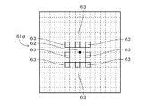
セル番号が付与されると、図6に示すセル番号「1」の網点セル712において、13画素からなる最小クラスタ61がセル中心7120を含む位置に設定される。図6では、最小クラスタ61の輪郭を太実線にて示している(図8においても同様)。また、セル番号「2」〜「16」の網点セル712(図5参照)においても同様に、同様の形状を有する最小クラスタ61がセル中心7120を含む位置に設定される。これにより、マトリクス空間に配置された網点セル712の個数と同じ個数(本実施の形態では、16個)の複数の最小クラスタ61が、マトリクス空間において互いに均一に離れた状態にて設定される(ステップS12)。
When the cell number is given, the
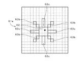
図6に示すように、最小クラスタ61は、9画素からなる矩形状(本実施の形態では、正方形状)のメインクラスタ62、および、メインクラスタ62の周囲に放射状に配置されたそれぞれ1画素からなる4つのサブクラスタ63を備える。
As shown in FIG. 6, the
最小クラスタ61は、その重心位置がセル中心7120に重なるように、あるいは、重心位置がセル中心7120に近接するように配置される。本実施の形態では、メインクラスタ62の正方形状に配列された9つの画素のうちの中心の画素の右上の頂点とセル中心7120とが重なる。
The
各サブクラスタ63の一の頂点は、メインクラスタ62の一の頂点と重なっており、他の頂点および全ての辺はメインクラスタ62と重なっていない。換言すれば、各サブクラスタ63は、メインクラスタ62と頂点のみにおいて接している。また、各サブクラスタ63は、メインクラスタ62の一対の辺に平行な第1の方向である図中の左右方向においてメインクラスタ62よりも小さく、かつ、第1の方向に垂直な第2の方向である図中の上下方向においてもメインクラスタ62よりも小さい。
One vertex of each sub-cluster 63 overlaps with one vertex of the
複数の最小クラスタ61が設定されると、セル番号「1」の網点セル712に設定された最小クラスタ61の全画素(すなわち、13の画素)に同一の閾値「0」が付与され(ステップS13)、次のセル番号の網点セル712の存否が確認される(ステップS14)。この場合、次の網点セル712が有ると判断されてステップS13に戻り、セル番号「2」の網点セル712に設定された最小クラスタ61の全画素に、セル番号「1」の網点セル712の最小クラスタ61に付与された閾値「0」よりも最小クラスタ61の画素数である13だけ大きい閾値「13」が付与された後、次の網点セル712の存否が再び確認される(ステップS13,S14)。
When a plurality of
そして、セル番号「3」〜「16」の網点セル712にそれぞれ設定された最小クラスタ61に対して、セル番号「2」の網点セル712に設定された最小クラスタ61に対して行われた処理と同様の処理が行われる。すなわち、一の最小クラスタ61に付与された閾値よりも最小クラスタ61の画素数である13だけ大きい閾値を次の最小クラスタ61の全画素に付与する工程が、セル番号「2」〜「16」の網点セル712にそれぞれ設定された最小クラスタ61に対して繰り返される(ステップS13,S14)。これにより、セル番号「3」の網点セル712に設定された最小クラスタ61では、13の画素に同一の閾値「26」が付与され、セル番号「4」〜「13」の網点セル712の最小クラスタ61にも同様に、閾値「39」「52」「65」「78」「91」「104」「117」「130」「143」「156」「169」「182」「195」が付与される。
Then, the
全ての最小クラスタ61に対する閾値の付与が終了すると、マトリクス空間の16個の最小クラスタ61を除く領域の各画素について、各画素が含まれる網点セル712のセル中心7120と各画素との間の距離が大きいほど大きくなる評価値が求められる。図7は、マトリクス空間の各網点セル712における評価値の分布を等高線にて示す図である。そして、評価値が最も小さい(すなわち、セル中心7120に最も近い)画素が選択され、選択された画素(以下、「選択画素」という。)に、セル番号「16」の網点セル712の最小クラスタ61に設定された閾値「195」よりも最小クラスタ61の画素数である13だけ大きい閾値「208」が付与される。
When the assignment of thresholds to all the
閾値マトリクス710の生成では、マトリクス空間の16個の最小クラスタ61を除く領域の複数の画素(本実施の形態では、3888個の画素)に対して、評価値の小さい画素から順に、「208」から「4095」まで1ずつ増加する整数の閾値が付与される(ステップS15)。換言すれば、最小クラスタ61に近い画素から順に1ずつ増加する閾値が付与され、これらの閾値は、元画像の階調レベルの増加に合わせて描画を行う画素の順序であり、露光の際のいわゆる点灯順序に対応する。すなわち、ステップS15では、マトリクス空間の16個の最小クラスタ61を除く領域に対して、元画像における階調レベルの増加に伴って網点画像において複数の最小クラスタ61に対応する複数の最小網点から網点領域が成長するように閾値が設定される。
In the generation of the
本実施の形態では、ステップS15において、まず、16個の網点セル712のそれぞれにて、図8中において平行斜線を付して示すように、メインクラスタ62の右上に位置するサブクラスタ63の左側の2つの画素、および、当該サブクラスタ63の下側の2つの画素が選択される(すなわち、マトリクス空間の64個の画素が選択画素とされる。)。そして、セル番号「1」の網点セル712に含まれる4つの選択画素のうち、セル中心7120を中心として最も左側かつ最も上側に位置する選択画素に閾値「208」が付与される。また、セル番号「2」〜「16」の網点セル712において、閾値「208」が付与された選択画素に対応する選択画素に、セル番号の小さい順に閾値「209」〜「223」が順に付与される。
In the present embodiment, in step S15, first, in each of the 16
続いて、セル番号「1」〜「16」の網点セル712において、閾値が付与された各選択画素の次の選択画素(例えば、閾値が付与された選択画素から最も遠い位置に位置する選択画素)に対して、セル番号の小さい順に閾値「224」〜「239」が付与される。以下同様に、セル番号「1」〜「16」の網点セル712のそれぞれにおいて、3番目の選択画素に対して、セル番号の小さい順に閾値「240」〜「255」が付与され、4番目の選択画素に対して、セル番号の小さい順に閾値「256」〜「271」が付与される。
Subsequently, in the
次に、各網点セル712において、閾値「208」〜「271」が付与された上記画素の次に評価値が小さい画素が選択画素とされ、選択画素が含まれる網点セル712のセル番号の小さい順に「272」から1ずつ増加する閾値が付与される。一の網点セル712に複数の選択画素が含まれている場合には、上記と同様に、当該複数の選択画素に定められた所定の順番にて、各網点セル712の最初の選択画素に閾値「272」〜「287」がセル番号の順に付与され、各網点セル712の次の選択画素に閾値「288」〜「303」がセル番号の順に付与され、当該複数の選択画素の全てに閾値が付与されるまで同様の手順が繰り返される。以下同様に、マトリクス空間の16個の最小クラスタ61を除く領域の全ての画素に対して閾値が順次付与される。
Next, in each
スクリーニングの階調数(すなわち、網掛けの階調数であり、本実施の形態では、元画像の階調数に等しくされる。)がマトリクス空間の画素数に等しい場合には(ステップS16)、上述のステップS13〜S15にてマトリクス空間の各画素に閾値が付与されることにより閾値マトリクス710の生成が終了する。
When the number of gradations for screening (that is, the number of shaded shades, which is equal to the number of gradations of the original image in this embodiment) is equal to the number of pixels in the matrix space (step S16). In step S13 to S15 described above, a threshold value is assigned to each pixel in the matrix space, thereby completing generation of the
また、スクリーニングの階調数がマトリクス空間の画素数と異なる場合には(ステップS16)、各画素に付与された閾値がスクリーニングの階調数に合わせて階調圧縮されることにより、各画素に最終的な閾値が割り当てられて閾値マトリクス710が生成される(ステップS17)。例えば、マトリクス空間の画素数がM個であり、スクリーニングの階調数がNである場合には、各画素に付与された閾値「0」〜「(M−1)」が((N−1)/(M−1))倍されることにより、最終的な閾値「0」〜「(N−1)」が各画素に割り当てられる。本実施の形態では、元画像70の階調数が4096(=12bit)とされ、マトリクス空間の画素数と元画像70の階調数とが等しいため、ステップS17は行われない。
Further, when the number of gradations for screening is different from the number of pixels in the matrix space (step S16), the threshold value assigned to each pixel is gradation-compressed according to the number of gradations for screening, so that each pixel is A final threshold value is assigned to generate a threshold value matrix 710 (step S17). For example, when the number of pixels in the matrix space is M and the number of gradations for screening is N, the thresholds “0” to “(M−1)” assigned to each pixel are ((N−1). ) / (M−1)), the final threshold values “0” to “(N−1)” are assigned to each pixel. In the present embodiment, the number of gradations of the
図1に示すコンピュータ11において閾値マトリクス710が生成されると、既述のように閾値マトリクス710および画像メモリ104に記憶されている元画像のデータが通信部109を介して画像記録装置12に転送され、図2に示すSPM23および画像メモリ21にそれぞれ記憶される。これにより、複数(本実施の形態では、16個)の網点セル712(図5参照)が配置される繰り返し領域71(図3参照)に対応するマトリクス空間を有するSPM23に閾値群が設定されることとなる(ステップS18)。
When the
そして、画像メモリ21内の繰り返し領域71の各画素の画素値(すなわち、画素の階調レベル)とSPM23のマトリクス空間内の対応する閾値とが比較器25にて比較されることにより、2値の網点画像におけるその画素の位置(アドレス)の画素値が決定される。具体的には、図3に示す元画像70(の一部)において、画素値が閾値マトリクス710の対応する閾値よりも大きい位置には、例えば、画素値「1」が付与され(すなわち、ドットが置かれ)、残りの画素には画素値「0」が付与される(すなわち、ドットは置かれない。)。このようにして、画像記録装置12では、信号生成回路123により元画像70が閾値マトリクス710を用いて網点化され、後述する網点記録時における光ビームのON/OFFを示す網点画像データが生成される(ステップS19)。
Then, the
網点画像の生成では、例えば、繰り返し領域71の全画素の階調レベルが「0」である場合、各画素の階調レベルが閾値マトリクス710に設定された閾値よりも大きくなることがないため、繰り返し領域71には網点は形成されない。すなわち、本実施の形態では、繰り返し領域71の全画素の階調レベルが「0」である状態は、繰り返し領域71に網点が存在しない最も低い階調レベルとなっている。
In the generation of a halftone image, for example, when the gradation level of all the pixels in the
図9.Aないし図9.Dは、元画像70の一の繰り返し領域71に対応する網点画像生成空間内の領域(すなわち、網点画像の一部)を示す図である。図9.Aないし図9.Dでは、網点画像の各網点セル712に対応する領域の輪郭を破線にて示しており、網点の輪郭を太実線にて示している。
FIG. A through FIG. D is a diagram showing a region in the halftone image generation space corresponding to one
図9.Aは、繰り返し領域71の各画素の階調レベルが「53」〜「65」の間である場合の網点画像の一部を示す図である。上述のように、閾値マトリクス710では、セル番号「1」〜「5」の網点セル712に設定された最小クラスタ61(図6参照)に閾値「0」「13」「26」「39」「52」が付与されており、セル番号「6」以上の網点セル712の最小クラスタ61には「65」以上の閾値が付与されているため、図9.Aに示す網点画像では、セル番号「1」〜「5」の網点セル712のセル中心7120(図6参照)に対応する5個の網点中心位置(いわゆる、ドットセンタ)に、最小クラスタ61に対応する最小網点66が形成され、それ以外の網点セル712に対応する領域には網点は形成されない。
FIG. A is a diagram showing a part of a halftone image when the gradation level of each pixel in the
最小網点66は、最小クラスタ61と同様に、9画素からなる矩形状(本実施の形態では、正方形状)のメインクラスタ67、および、メインクラスタ67の周囲に放射状に配置されたそれぞれ1画素からなる4つのサブクラスタ68を備える。
Similar to the
各サブクラスタ68の一の頂点は、メインクラスタ67の一の頂点と重なっており、他の頂点および全ての辺はメインクラスタ67と重なっていない。換言すれば、各サブクラスタ68は、メインクラスタ67と頂点のみにおいて接している。また、各サブクラスタ68は、メインクラスタ67の一対の辺に平行な第1の方向である図中の左右方向においてメインクラスタ67よりも小さく、かつ、第1の方向に垂直な第2の方向である図中の上下方向においてもメインクラスタ67よりも小さい。
One vertex of each sub-cluster 68 overlaps with one vertex of the
図9.Bは、繰り返し領域71の各画素の階調レベルが「196」〜「208」の間である場合の網点画像の一部を示す図である。上述のように、閾値マトリクス710では、各網点セル712に設定された最小クラスタ61に「195」以下の閾値が付与されており、「208」以上の閾値は最小クラスタ61の周囲の画素に付与されているため、図9.Bに示す網点画像では、全ての網点セル712のセル中心7120に対応する16個の網点中心位置に最小網点66が形成され、最小網点66以外の画素の画素値は「0」とされる。
FIG. B is a diagram illustrating a part of a halftone image when the gradation level of each pixel in the
図9.Cは、繰り返し領域71の各画素の階調レベルが一様に「216」である場合の網点画像の一部を示す図である。上述のように、閾値マトリクス710では、閾値「208」〜「223」は、セル番号「1」〜「16」の網点セル712の最小クラスタ61にそれぞれ隣接する一の画素に付与されているため、図9.Cに示す網点画像では、セル番号「1」〜「8」の網点セル712のセル中心7120に対応する8個の網点中心位置に最小網点から1画素だけ成長した網点69aが形成され、セル番号「9」〜「16」の網点セル712のセル中心7120に対応する8個の網点中心位置に最小網点66が形成される。
FIG. C is a diagram illustrating a part of a halftone image in a case where the gradation level of each pixel in the
図9.Dは、繰り返し領域71の各画素の階調レベルが一様に「232」である場合の網点画像の一部を示す図である。上述のように、閾値マトリクス710では、閾値「208」〜「223」は、セル番号「1」〜「16」の網点セル712の最小クラスタ61にそれぞれ隣接する一の画素に付与され、閾値「224」〜「239」は、セル番号「1」〜「16」の網点セル712の最小クラスタ61にそれぞれ隣接するもう1つの画素に付与されているため、図9.Dに示す網点画像では、セル番号「1」〜「8」の網点セル712のセル中心7120に対応する8個の網点中心位置に最小網点から2画素だけ成長した網点69bが形成され、セル番号「9」〜「16」の網点セル712のセル中心7120に対応する8個の網点中心位置に最小網点から1画素だけ成長した網点69aが形成される。
FIG. D is a diagram showing a part of a halftone image in the case where the gradation level of each pixel in the
網点画像の生成では、上述のように、繰り返し領域71の各画素の階調レベルが「208」以下の場合、繰り返し領域71における階調レベルが高いほど最小網点66の密度が高くなるように、閾値マトリクス710の複数の網点セル712のセル中心7120に対応する複数の網点中心位置(すなわち、予め定められた複数の網点中心位置)のいずれかに最小網点66が形成される。
In the generation of the halftone image, as described above, when the gradation level of each pixel in the
また、繰り返し領域71の各画素の階調レベルが「208」よりも高い場合、繰り返し領域71における階調レベルが高いほど最小網点66から成長した網点が各網点中心位置に形成される。具体的には、繰り返し領域71における各画素の階調レベルが「209」から高くなるに従って、対応する網点セル712のセル番号が小さい網点中心位置から順に、最小網点66から1画素だけ成長した網点69aが形成され、全ての網点中心位置に網点69aが形成されると、対応する網点セル712のセル番号が小さい網点中心位置から順に、網点69aから1画素だけ成長した網点69bが形成される。換言すれば、繰り返し領域71の階調レベルが「209」から高くなるに従って、複数の網点中心位置に形成された複数の網点が、図7に示す等高線の広がりに沿って円形に成長していく。
Further, when the gradation level of each pixel in the
このように、網点画像の形成では、「0」〜「4095」の値を取り得る繰り返し領域71の階調レベルが「208」以下の場合、繰り返し領域71の階調レベルが高くなるに従って最小網点66の個数が増加し、繰り返し領域71の階調レベルが「208」よりも高い場合、繰り返し領域71の階調レベルが高くなるに従って網点の個数は変更されることなく網点が成長する。
As described above, in the formation of a halftone image, when the gradation level of the repeating
すなわち、階調レベル「208」は、網点画像の形成における網点の変化の態様(モード)が、個数の増加から成長に切り換えられる予め設定されたモード切替階調レベルとなっており、当該モード切替階調レベルは、網点が存在しない最も低い階調レベル「0」に近い階調レベルとされる。モード切替階調レベルは、生成される網点画像の解像度A(2400dpi)、解像度Aに対応する単位長さ(1インチ)当たりの網点の線数B(150)、最小網点66の画素数C(13)、最も低い階調レベル「0」から最も高い階調レベル「4095」までの階調数G(4096)を用いると、Gの100×C/((A/B)×(A/B))%として表され、本実施の形態では約5%とされる。したがって、モード切替階調レベルにおける網点面積率(すなわち、単位面積当たりに網点が占める割合)は約5%となる。 That is, the gradation level “208” is a preset mode switching gradation level in which the change mode (mode) of the halftone dot in the formation of the halftone image is switched from the increase in the number to the growth. The mode switching gradation level is a gradation level close to the lowest gradation level “0” where no halftone dot exists. The mode switching gradation level includes the resolution A (2400 dpi) of the generated halftone image, the number of halftone dots B per unit length (1 inch) corresponding to the resolution A (150), and the minimum halftone dot 66 pixels. Using the number C (13), the number of gradations G (4096) from the lowest gradation level “0” to the highest gradation level “4095”, 100 × C / ((A / B) × ( A / B))%, which is about 5% in the present embodiment. Therefore, the halftone dot area ratio (that is, the ratio of halftone dots per unit area) at the mode switching gradation level is about 5%.
実際の網点画像の生成では、多階調の元画像70の複数の画素は「0」〜「4095」の様々な値を有しており、元画像70においてモード切替階調レベル以下の階調レベルの領域に対応する網点画像生成空間内の領域において(すなわち、網点画像の一部であって対応する元画像70の領域の階調レベルがモード切替階調レベル以下である部分において)、元画像70における階調レベルが高いほど高い密度となるように最小網点66が複数の網点中心位置のいずれかに形成され、元画像70においてモード切替階調レベルよりも高い階調レベルの領域に対応する網点画像生成空間内の領域において(すなわち、網点画像の一部であって対応する元画像70の領域の階調レベルがモード切替階調レベルよりも高い部分において)、元画像70における階調レベルが高いほど最小網点66から成長した網点が各網点中心位置に形成される。
In the actual generation of a halftone dot image, a plurality of pixels of the multi-tone
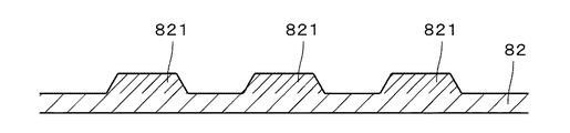
図10は、凸版印刷用の刷版に網点画像を形成する作業の流れを示す図であり、図11.Aないし図11.Cは、網点画像の形成途上の版材80の一部を示す断面図である。刷版に網点画像が形成される際には、まず、図1に示す画像記録装置12において、上述のステップS11〜S19(図4.Aおよび図4.B参照)にて生成された網点画像データに基づいて版材80のマスク層に光ビームが照射されることにより、マスク層の一部がアブレーションにより除去され、図11.Aに示すように、版材80のマスク層81に網点画像に対応する開口811が形成される(ステップS21)。本実施の形態では、版材80の感光性樹脂層82が紫外線硬化性の感光性樹脂により形成されているため、マスク層81において網点画像の網点に対応する部位に開口811が形成される。
FIG. 10 is a diagram showing a flow of work for forming a halftone image on a printing plate for letterpress printing. A thru | or FIG. C is a cross-sectional view showing a part of the
続いて、版材80が画像記録装置12から搬出され、マスク層81の開口811を介して感光性樹脂層82に紫外線が照射されることにより、図11.Bにおいて二点鎖線にて囲むとともに平行斜線の間隔を狭めて示すように、感光性樹脂層82のマスク層81近傍の部位のうちマスク層81の開口811と対向する部位(すなわち、感光性樹脂層82のマスク層81と対向する部位の一部)が硬化されて硬化部821となる(ステップS22)。
Subsequently, the
次に、版材80に対して現像液を付与しつつブラシにて洗い出しを行うことにより(すなわち、現像処理を行うことにより)、マスク層81、および、感光性樹脂層82のマスク層81と対向する部位のうち硬化部821を除く部位である硬化部821の周囲の部位が除去される(ステップS23)。そして、感光性樹脂層82が乾燥された後、再度露光されることにより感光性樹脂層82に含まれる粘着成分が除去されることにより、図11.Cに示すように、硬化部821が凸部となる感光性樹脂層82が、網点画像に対応する凸部を有する刷版として形成される。当該刷版の網点面積率が小さい(網点の密度が低い)ハイライト領域では、図9.Aおよび図9.Bに示す最小網点66(すなわち、図9.Aに示す9画素からなる正方形状のメインクラスタ67、および、メインクラスタ67の周囲に放射状に配置されたそれぞれ1画素からなる4つのサブクラスタ68)に対応する凸部(レリーフ)が形成される。
Next, by washing out with a brush while applying a developer to the plate member 80 (that is, by performing development processing), the
ここで、図12.Aのように、図中の右側のハイライト領域に形成される最小網点が4画素からなる正方形状とされる比較例の網点画像を想定した場合、このような網点画像に基づいて形成された凸版印刷用の刷版では、最小網点が小さすぎるため、図12.Bに示すように、最小網点に対応する凸部の高さが不足するレリーフの形成不良が生じてしまう。なお、図12.Bは、刷版の表面を電子顕微鏡により撮影した画像である(図12.D、図13.B、図13.Dおよび図13.Fにおいても同様)。 Here, FIG. When a halftone image of a comparative example in which the minimum halftone dot formed in the highlight area on the right side in the drawing is a square shape of four pixels as in A is assumed, based on such a halftone dot image, In the formed printing plate for letterpress printing, the minimum halftone dot is too small. As shown in B, there is a relief formation defect in which the height of the convex portion corresponding to the minimum halftone dot is insufficient. In addition, FIG. B is an image obtained by photographing the surface of the printing plate with an electron microscope (the same applies to FIGS. 12.D, 13.B, 13.D, and 13.F).
また、図12.Cのように、図中の右側のハイライト領域に形成される最小網点が16画素からなる正方形状とされる比較例の網点画像を想定した場合、このような網点画像に基づいて形成された凸版印刷用の刷版では、最小網点のピッチ(すなわち、隣接する最小網点の中心間の距離)が大きくなってしまい、図12.Dに示すように、最小網点に対応する凸部が折れ曲がる等のレリーフの形成不良が生じてしまう。 FIG. Assuming a halftone dot image of a comparative example in which the minimum halftone dot formed in the highlight area on the right side in the figure is a square shape of 16 pixels, as shown in C, based on such a halftone dot image, In the formed relief printing plate, the pitch of the minimum halftone dots (that is, the distance between the centers of adjacent minimum halftone dots) becomes large, and FIG. As shown in D, the formation of a relief such as a convex portion corresponding to the minimum halftone dot is bent occurs.
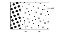
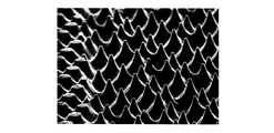
図13.A、図13.Cおよび図13.Eは、本実施の形態に係る閾値マトリクス710により生成された網点画像を示す図であり、図13.B、図13.Dおよび図13.Fはそれぞれ、図13.A、図13.Cおよび図13.Eに示す網点画像に基づいて形成された凸版印刷用の刷版の表面を示す図である。図13.A、図13.Cおよび図13.E中の右側の領域は、最小網点66のみが形成されたハイライト領域であり、それぞれのハイライト領域における網点面積率は約1%、約2%および約5%である。
FIG. A, FIG. C and FIG. E is a diagram showing a halftone image generated by the
本実施の形態に係る網点画像では、図13.A、図13.Cおよび図13.Eに示す最小網点66において、9画素からなる正方形状のメインクラスタ67(図9.A参照)の周囲にメインクラスタ67と接するサブクラスタ68(図9.A参照)が配置される。このため、凸版印刷用の刷版に形成される網点画像の最小網点66に対応する凸部において、メインクラスタ67に対応する凸部が、その周囲に形成されるサブクラスタ68に対応する凸部によりサポートされ、最小網点66に対応するレリーフの強度が向上される。これにより、図13.B、図13.Dおよび図13.Fに示すように、最小網点66に対応するレリーフがハイライト領域の網点面積率にかかわらず正常に形成され、その結果、凸版印刷用の刷版に形成される網点画像の印刷再現性(特に、印刷時の細部再現性)を向上することができる。
In the halftone image according to the present embodiment, FIG. A, FIG. C and FIG. At a
特に、図9.Aに示すように、4つのサブクラスタ68がメインクラスタ67の4つの頂点に接して設けられる(すなわち、メインクラスタ67の周囲に4つのサブクラスタ68が放射状に配置される)ことにより、刷版に形成される網点画像の最小網点66に対応する凸部において、サブクラスタ68に対応する凸部によりメインクラスタ67に対応する凸部がより強固にサポートされ、最小網点66に対応するレリーフの強度がより向上される。これにより、凸版印刷用の刷版に形成される網点画像の印刷再現性をより向上することができる。
In particular, FIG. As shown in A, the four
さらには、上記網点画像の最小網点66では、メインクラスタ62の一対の辺に平行な第1の方向においてサブクラスタ68がメインクラスタ67よりも小さく、かつ、第1の方向に垂直な第2の方向においてサブクラスタ68がメインクラスタ67よりも小さくされることにより、サブクラスタ68が過剰に大きくなって最小網点66の画素数が過剰に大きくなることが防止される。これにより、網点画像のハイライト領域において(特に、網点面積率が小さい場合に)最小網点66のピッチが過大となることが防止され、最小網点66に対応するレリーフの強度低下が防止される。
Furthermore, in the
画像記録システム1では、ステップS11〜S15(または、S11〜S17)の処理により、上述の閾値マトリクス710を容易に得ることができ、当該閾値マトリクス710を利用することにより、上記最小網点66を有する網点画像を容易に形成することができる。また、ステップS21〜S23の処理により、最小網点66に対応するレリーフの強度が向上された網点画像を有する刷版を容易に得ることができ、当該刷版を利用することにより、網点画像の印刷再現性を向上することができる。
In the
上記実施の形態では、閾値マトリクス710における最小クラスタ61、メインクラスタ62およびサブクラスタ63のそれぞれの画素数が、13、9および1とされるが、最小クラスタおよびメインクラスタの画素数がそれぞれ3以上および2以上とされ、かつ、サブクラスタの画素数がメインクラスタの画素数よりも少なくされるのであれば、各クラスタの画素数は様々に変更されてよい。網点画像においても同様に、最小網点66およびメインクラスタ67の画素数はそれぞれ3以上および2以上とされ、サブクラスタ68の画素数がメインクラスタ67の画素数より少なくされていればよい。例えば、最小クラスタ61の各サブクラスタは複数の画素であってもよく、この場合、当該複数の画素はメインクラスタからおよそ離れる方向へと配列され、当該複数の画素のうちメインクラスタに最も近い一の画素は、メインクラスタと頂点のみにおいて接し、または、メインクラスタの辺よりも短い辺のみにおいてメインクラスタと接する(最小網点66のサブクラスタにおいても同様)。
In the above embodiment, the number of pixels of the
また、上記実施の形態では、4つのサブクラスタ63がメインクラスタ62の周囲に配置されるが、最小クラスタ61では、1つのサブクラスタ63のみが設けられてもよく、あるいは、2つ以上のサブクラスタ63が互いに接しない状態にてメインクラスタ62の周囲に設けられてもよい(最小網点66においても同様)。以下、本発明に係る閾値マトリクスの最小クラスタの他の好ましい例について説明するが、以下の最小クラスタに関する説明は、網点画像の最小網点においても同様である。
In the above embodiment, four
図14.Aに示す最小クラスタ61aは、9画素からなる正方形状のメインクラスタ62、および、メインクラスタ62の周囲に放射状に配置されたそれぞれ1画素からなる4つのサブクラスタ63を備え、各サブクラスタ63は、メインクラスタ62の一の辺の中央にて当該辺よりも短い辺のみにおいてメインクラスタ62と接する。図14.Aでは、メインクラスタ62およびサブクラスタ63の輪郭を太実線にて示している(図14.B、図14.C、並びに、図15.Aないし図15.Iにおいても同様)。最小クラスタ61aがマトリクス空間に設定される閾値マトリクスを用いて凸版印刷用の刷版に網点画像を形成する場合も、上述の刷版の形成と同様に、刷版の最小網点に対応する凸部において、メインクラスタに対応する凸部がサブクラスタに対応する凸部によりサポートされ、最小網点に対応するレリーフの強度が向上される。
FIG. A
図14.Bに示す最小クラスタ61bは、図14.Aと同様のメインクラスタ62、および、メインクラスタ62の周囲に放射状に配置された4つのサブクラスタ63aを備える。各サブクラスタ63aは2画素からなり、メインクラスタ62に最も近い方の画素の一の辺にて、当該辺よりも長いメインクラスタ62の辺に接する。各サブクラスタ63aの2つの画素は、当該サブクラスタ63aが接するメインクラスタ62の辺に垂直な方向に沿ってメインクラスタ62から離れる方向へと1列に配列される。最小クラスタ61bがマトリクス空間に設定される閾値マトリクスを用いて凸版印刷用の刷版に網点画像を形成する場合も、上述の刷版の形成と同様に、最小網点に対応するレリーフの強度を向上することができる。また、サブクラスタ63aが1列に配列された複数の画素であることにより、刷版の最小網点に対応する凸部において、メインクラスタに対応する凸部がサブクラスタに対応する凸部によりさらに強固にサポートされるため、最小網点に対応するレリーフの強度がより向上される。
FIG. The
図14.Cに示す最小クラスタ61cは、図14.Aと同様のメインクラスタ62、および、メインクラスタ62の周囲に放射状に配置された4つのサブクラスタ63bを備える。各サブクラスタ63bは、メインクラスタ62の対角線に沿ってメインクラスタ62から離れる方向へと1列に配列された2つの画素であり、メインクラスタ62に最も近い方の画素の一の頂点にて、メインクラスタ62の一の頂点に接する。また、サブクラスタ63bの2つの画素同士も一の頂点のみにて接している。最小クラスタ61cがマトリクス空間に設定される閾値マトリクスを用いて凸版印刷用の刷版に網点画像を形成する場合も、上述の刷版の形成と同様に、最小網点に対応するレリーフの強度を向上することができる。また、最小クラスタ61bが用いられる刷版の形成と同様に、1列に配列された複数の画素からなるサブクラスタ63bにより、最小網点に対応するレリーフの強度がより向上される。
FIG. The
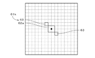
図15.Aないし図15.Iは、本発明に係る閾値マトリクスの最小クラスタの他の例を示す図であり、以下の最小クラスタに関する説明は、網点画像の最小網点においても同様である。図15.Aに示す最小クラスタ61dでは、それぞれ1画素からなる8つのサブクラスタ63がメインクラスタ62の周囲に放射状に配置される。図15.Bに示す最小クラスタ61eでは、図14.Cと同様の4つのサブクラスタ63bがメインクラスタ62の頂点に接し、それぞれ3画素からなる4つのサブクラスタ63cがメインクラスタ62の辺に接する。
FIG. A thru | or FIG. I is a figure which shows the other example of the minimum cluster of the threshold value matrix which concerns on this invention, and the description regarding the following minimum clusters is the same also about the minimum halftone dot of a halftone image. FIG. In the
図15.Cに示す最小クラスタ61fでは、メインクラスタ62の一の辺に垂直な方向に沿って伸びる4つのサブクラスタ63aが、メインクラスタ62の頂点に接する。図15.Dに示す最小クラスタ61gでは、それぞれが4画素からなる正方形状の4つのサブクラスタ63dがメインクラスタ62の頂点に接する。
FIG. In the
図15.Eに示す最小クラスタ61hは、4画素からなる正方形状のメインクラスタ62a、および、図6と同様の4つのサブクラスタ63を備える。図15.Fに示す最小クラスタ61iは、図15.Eと同様のメインクラスタ62a、および、図14.Cと同様の4つのサブクラスタ63bを備える。最小クラスタ61iでは、メインクラスタ62aの一対の辺に平行な第1の方向、および、第1の方向に垂直な第2の方向において、メインクラスタ62aの大きさと各サブクラスタ63bの大きさとが等しい。
FIG. The
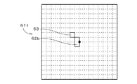
図15.Gに示す最小クラスタ61jは、図15.Eと同様のメインクラスタ62a、および、それぞれ3画素からなる4つのサブクラスタ63dを備え、各サブクラスタ63dは、メインクラスタ62aの対角線に沿って1列に配列されるとともに、メインクラスタ62aに最も近い画素の一の頂点のみにてメインクラスタ62aに接する。最小クラスタ61jでは、上記第1の方向および第2の方向において、各サブクラスタ63dがメインクラスタ62aよりも大きい。
FIG. The minimum cluster 61j shown in FIG. A
図15.Hに示す最小クラスタ61kは、図15.Eと同様のメインクラスタ62a、および、それぞれ1画素からなる2つのサブクラスタ63を備え、2つのサブクラスタ63は、メインクラスタ62aと頂点のみにて接する。また、図15.Iに示す最小クラスタ61lは、2画素からなる長方形状のメインクラスタ62b、および、メインクラスタ62bと頂点のみにて接する1つのサブクラスタ63を備える。図15.Hおよび図15.Iに示すように、メインクラスタおよびメインクラスタに接する1つ以上のサブクラスタを有する最小クラスタがマトリクス空間に設定された閾値マトリクスを用いて凸版印刷用の刷版に網点画像を形成することにより、上述の刷版の形成と同様に、最小網点に対応する(すなわち、最小クラスタに対応する)レリーフの強度が向上される。
FIG. The
なお、図6に示す最小クラスタ61は、図15.Iに示す最小クラスタ61lと同様に、1つのメインクラスタ62、および、1つのサブクラスタ63を備え、これに加えて、当該サブクラスタ63と同形状であって当該サブクラスタ63と共にメインクラスタ62の周囲に放射状に配置される3つのサブクラスタ63をさらに備える構造であると捉えられる。また、図9.Aに示す最小網点66は、1つのメインクラスタ67、および、1つのサブクラスタ68を備え、さらに、当該サブクラスタ68と同形状であって当該サブクラスタ68と共にメインクラスタ67の周囲に放射状に配置された3つのサブクラスタ68を備える構造であると捉えられる。
The
以上、本発明の実施の形態について説明してきたが、本発明は上記実施の形態に限定されるものではなく、様々な変更が可能である。 As mentioned above, although embodiment of this invention has been described, this invention is not limited to the said embodiment, A various change is possible.
上述の網点画像における網点の形状は、必ずしも略円形とされる必要はなく、例えば、略楕円形の網点(いわゆる、エリプチカルドット)を有する網点画像が凸版印刷用の刷版に形成されてもよい。 The shape of the halftone dots in the above halftone image need not be substantially circular. For example, a halftone dot image having a substantially elliptic halftone dot (so-called elliptical dot) is a printing plate for letterpress printing. May be formed.
上記実施の形態では、規則的に配置された網点の大きさを変えることにより階調表現が実現されるAMスクリーニングを利用して網点画像が生成されるが、網点画像の生成は、ランダムに配置された網点の大きさを変更することにより階調表現を実現するいわゆるハイブリッドスクリーニング(すなわち、AMスクリーニングとFM(Frequency Modulated)スクリーニングとのハイブリッド)を利用して行われてもよい。この場合、不規則な形状の複数の網点セル712がランダムかつおよそ一様にマトリクス空間に配置され、上述のステップS12において、網点セル712の個数と同じ個数の複数の最小クラスタ61が、互いにおよそ均一に離れた状態にてマトリクス空間に設定される。また、網点画像の形成におけるモード切替階調レベルを全階調数Gの100×C/((A/B)×(A/B))%として表す際の網点の線数Bは、単位面積当たりの網点の個数に基づいて定義される。
In the above embodiment, a halftone image is generated using AM screening in which gradation expression is realized by changing the size of regularly arranged halftone dots. You may perform using what is called hybrid screening (namely, hybrid of AM screening and FM (Frequency Modulated) screening) which implement | achieves a gradation expression by changing the magnitude | size of the halftone dot arrange | positioned at random. In this case, a plurality of irregularly-shaped
上記実施の形態に係る網点画像の生成では、モード切替階調レベルを全階調数Gの100×C/((A/B)×(A/B))%とし、モード切替階調レベル以上の階調レベルの範囲において、元画像の階調レベルと網点画像の階調レベルとが等しいものとして説明しているが、モード切替階調レベルは必ずしもGの100×C/((A/B)×(A/B))%とされる必要はなく、例えば、Gの100×C/((A/B)×(A/B))%よりも大きい値とされてもよい。この場合、全網点セル712に最小網点66が設定される階調レベルは、上記実施の形態に比べて高くなり、モード切替階調レベルよりも高い階調レベルにおいて、元画像の階調レベルの増大に対する網点画像の階調レベルの増大の割合が元画像よりも大きくなる。
In the generation of the halftone image according to the above embodiment, the mode switching gradation level is set to 100 × C / ((A / B) × (A / B))% of the total number of gradations G, and the mode switching gradation level is set. In the above gradation level range, the gradation level of the original image is assumed to be equal to the gradation level of the halftone image, but the mode switching gradation level is not necessarily 100 × C / ((A / B) × (A / B))% is not necessary, and may be a value larger than 100 × C / ((A / B) × (A / B))% of G, for example. In this case, the gradation level at which the
上述の閾値マトリクスでは、マトリクス空間に設定される複数の網点セルを、ハイライト側の階調レベルの変化に対して網点領域が変化する複数のハイライト側網点セルグループ、および、シャドウ側の階調レベルの変化に対して網点領域が変化する複数のシャドウ側網点セルグループにグループ分けし、ハイライト側網点セルに最大階調レベルの半分以下の値の閾値がセル中心にて極小となるように与えられ、シャドウ側網点セルに最大階調レベルの半分以上の値の閾値がセル中心にて極大となるように与えられてもよい。これにより、元画像の階調レベルが0%から50%へと増大するとハイライト側網点セルにてセル中心から網点領域が成長し、階調レベルが50%から100%へと増大するとシャドウ側網点セルの周囲からセル中心に向かって網点領域が成長する(白いドットがセル中心に向かって縮退する)こととなる。この場合であっても、ハイライト側網点セルのセル中心を含む位置に上述の最小クラスタを設定することにより、最小網点に対応するレリーフの強度が向上される。 In the threshold matrix described above, a plurality of halftone cells set in the matrix space are replaced with a plurality of highlight side halftone cell groups whose halftone area changes with respect to a change in highlight side gradation level, and shadows. Grouped into a plurality of shadow side halftone cell groups whose halftone dot area changes with respect to the change in the gray level on the side, and the threshold value with a value equal to or less than half the maximum gray level in the highlight side halftone cell The shadow side halftone cell may be given a threshold value that is at least half of the maximum gradation level at the cell center. As a result, when the gradation level of the original image increases from 0% to 50%, a halftone dot region grows from the cell center in the highlight side halftone cell, and the gradation level increases from 50% to 100%. A halftone dot region grows from the periphery of the shadow side halftone cell toward the cell center (white dots are degenerated toward the cell center). Even in this case, the strength of the relief corresponding to the minimum halftone dot is improved by setting the above-mentioned minimum cluster at a position including the cell center of the highlight side halftone cell.
版材80の感光性樹脂層82は、必ずしも紫外線硬化性の感光樹脂により形成される必要はなく、紫外線以外の光が照射されることにより硬化する感光性樹脂により形成されてもよい。また、感光性樹脂層82は、紫外線や紫外線以外の光の照射により可溶化する感光性樹脂により形成されてもよい。このように、光の照射により可溶化する感光性樹脂により感光性樹脂層82が形成される場合には、上述のステップS21においてマスク層81に形成される網点画像に対応する開口は、網点画像の網点を除く部位とされ、ステップS22において感光性樹脂層82の硬化部とされる部位は、感光性樹脂層82のうち、マスク層81の一部であるマスク層81の開口を除く部位と対向する部位となる。
The
上述の網点画像が形成される刷版は、必ずしも感光性樹脂により形成される必要はなく、金属等の他の材料により形成された刷版に上述の網点画像が形成されてもよい。 The printing plate on which the above-described halftone image is formed is not necessarily formed of a photosensitive resin, and the above-described halftone image may be formed on a printing plate formed of another material such as metal.
61,61a〜61l 最小クラスタ
62,62a,62b メインクラスタ
63,63a〜63d サブクラスタ
66 最小網点
67 メインクラスタ
68 サブクラスタ
69a,69b 網点
70 元画像
80 版材
81 マスク層
82 感光性樹脂層
710 閾値マトリクス
712 網点セル
811 開口
821 硬化部
S11〜S19,S21〜S23 ステップ
61, 61a to 61l
Claims (12)
網点が存在しない最も低い階調レベルに近いモード切替階調レベルが予め設定されており、多階調の元画像において前記モード切替階調レベル以下の階調レベルの領域に対応する網点画像生成空間内の領域において、前記元画像における階調レベルが高いほど高い密度となるように3以上の画素からなる最小網点を予め定められた複数の網点中心位置のいずれかに形成する工程と、
前記元画像において前記モード切替階調レベルよりも高い階調レベルの領域に対応する前記網点画像生成空間内の領域において、前記元画像における階調レベルが高いほど前記最小網点から成長した網点を各網点中心位置に形成する工程と、
を備え、
前記最小網点が、
2以上の画素からなる矩形状のメインクラスタと、
前記メインクラスタの周囲に配置され、前記メインクラスタの画素数よりも少ない数の画素からなるサブクラスタと、
を備え、
前記サブクラスタが、一の画素、または、前記メインクラスタからおよそ離れる方向へと配列された複数の画素であり、前記メインクラスタと頂点のみにおいて、または、前記メインクラスタの辺よりも短い辺のみにおいて前記メインクラスタと接することを特徴とする網点画像生成方法。 A halftone image generation method for generating a halftone image formed on a printing plate for letterpress printing,
A mode switching gradation level close to the lowest gradation level where there is no halftone dot is preset, and a halftone image corresponding to an area of a gradation level equal to or lower than the mode switching gradation level in a multi-tone original image Forming a minimum halftone dot composed of three or more pixels at any one of a plurality of predetermined halftone dot center positions so that the higher the gradation level in the original image, the higher the density in the region in the generation space. When,
In a region in the halftone image generation space corresponding to a region having a gradation level higher than the mode switching gradation level in the original image, a halftone dot that has grown from the minimum halftone dot as the gradation level in the original image increases. Forming a point at each dot center position;
With
The minimum halftone dot is
A rectangular main cluster of two or more pixels;
A sub-cluster that is arranged around the main cluster and includes a smaller number of pixels than the number of pixels of the main cluster;
With
The sub-cluster is a single pixel or a plurality of pixels arranged in a direction approximately away from the main cluster, and only in the main cluster and the vertex, or only in a side shorter than the side of the main cluster A halftone image generating method, wherein the halftone image is in contact with the main cluster.
生成される網点画像の解像度をA、前記解像度に対応する単位長さ当たりの網点の線数をB、前記最小網点の画素数をC、前記最も低い階調レベルから最も高い階調レベルまでの階調数をGとして、前記モード切替階調レベルが、Gの100×C/((A/B)×(A/B))%であることを特徴とする網点画像生成方法。 The halftone image generation method according to claim 1,
The resolution of the generated halftone image is A, the number of lines of halftone dots per unit length corresponding to the resolution is B, the number of pixels of the minimum halftone dot is C, the highest gradation from the lowest gradation level A halftone image generation method, wherein the number of gradations up to the level is G, and the mode switching gradation level is 100 × C / ((A / B) × (A / B))% of G .
前記メインクラスタの一対の辺に平行な第1の方向において前記サブクラスタが前記メインクラスタよりも小さく、かつ、前記第1の方向に垂直な第2の方向において前記サブクラスタが前記メインクラスタよりも小さいことを特徴とする網点画像生成方法。 The halftone image generation method according to claim 1 or 2,
The sub-cluster is smaller than the main cluster in a first direction parallel to a pair of sides of the main cluster, and the sub-cluster is smaller than the main cluster in a second direction perpendicular to the first direction. A halftone dot image generation method characterized by being small.
前記サブクラスタが、1列に配列された複数の画素であることを特徴とする網点画像生成方法。 A halftone dot image generation method according to any one of claims 1 to 3,
The halftone image generating method, wherein the sub-cluster is a plurality of pixels arranged in one column.
前記最小網点が、前記サブクラスタと同形状であり、前記サブクラスタと共に前記メインクラスタの周囲に放射状に配置された3つのサブクラスタをさらに備えることを特徴とする網点画像生成方法。 A halftone dot image generation method according to any one of claims 1 to 4,
The halftone dot image generation method further comprising three subclusters having the same minimum dot shape as the subcluster and arranged radially around the main cluster together with the subcluster.
a)3以上の画素からなる複数の最小クラスタを、互いにおよそ均一に離れた状態にて、前記閾値マトリクスが生成されるマトリクス空間に設定する工程と、
b)一の最小クラスタの全画素に同一の閾値を付与し、次の最小クラスタが有る場合に、前記次の最小クラスタの全画素に、前記一の最小クラスタに付与された閾値よりも最小クラスタの画素数だけ大きい閾値を付与する工程と、
c)前記複数の最小クラスタに対して前記b)工程を順次繰り返す工程と、
d)元画像における階調レベルの増加に伴って網点画像において前記複数の最小クラスタに対応する複数の最小網点から網点領域が成長するように、前記マトリクス空間の前記複数の最小クラスタを除く領域に閾値を設定する工程と、
を備え、
前記最小クラスタが、
2以上の画素からなる矩形状のメインクラスタと、
前記メインクラスタの周囲に配置され、前記メインクラスタの画素数よりも少ない数の画素からなるサブクラスタと、
を備え、
前記サブクラスタが、一の画素、または、前記メインクラスタからおよそ離れる方向へと配列された複数の画素であり、前記メインクラスタと頂点のみにおいて、または、前記メインクラスタの辺よりも短い辺のみにおいて前記メインクラスタと接することを特徴とする閾値マトリクス生成方法。 A threshold value matrix generation method for generating a threshold value matrix to be compared with a multi-tone original image represented by the halftone image when generating a halftone image formed on a printing plate for letterpress printing,
a) setting a plurality of minimum clusters composed of three or more pixels in a matrix space in which the threshold value matrix is generated in a state of being approximately uniformly spaced from each other;
b) Assigning the same threshold value to all the pixels of one minimum cluster, and if there is a next minimum cluster, all the pixels of the next minimum cluster have a minimum cluster than the threshold value assigned to the one minimum cluster. A step of assigning a threshold value larger by the number of pixels of
c) sequentially repeating the step b) for the plurality of minimum clusters;
d) The plurality of minimum clusters in the matrix space are set such that a halftone dot region grows from a plurality of minimum halftone dots corresponding to the plurality of minimum clusters in the halftone image as the gradation level in the original image increases. Setting a threshold value for the excluded area;
With
The minimum cluster is
A rectangular main cluster of two or more pixels;
A sub-cluster that is arranged around the main cluster and includes a smaller number of pixels than the number of pixels of the main cluster;
With
The sub-cluster is a single pixel or a plurality of pixels arranged in a direction approximately away from the main cluster, and only in the main cluster and the vertex, or only in a side shorter than the side of the main cluster A threshold value matrix generation method characterized by contacting with the main cluster.
前記メインクラスタの一対の辺に平行な第1の方向において前記サブクラスタが前記メインクラスタよりも小さく、かつ、前記第1の方向に垂直な第2の方向において前記サブクラスタが前記メインクラスタよりも小さいことを特徴とする閾値マトリクス生成方法。 The threshold value matrix generation method according to claim 6,
The sub-cluster is smaller than the main cluster in a first direction parallel to a pair of sides of the main cluster, and the sub-cluster is smaller than the main cluster in a second direction perpendicular to the first direction. A threshold matrix generation method characterized by being small.
前記サブクラスタが、1列に配列された複数の画素であることを特徴とする閾値マトリクス生成方法。 The threshold value matrix generation method according to claim 6 or 7,
The threshold matrix generating method, wherein the sub-cluster is a plurality of pixels arranged in one column.
前記最小クラスタが、前記サブクラスタと同形状であって前記サブクラスタと共に前記メインクラスタの周囲に放射状に配置された3つのサブクラスタをさらに備えることを特徴とする閾値マトリクス生成方法。 The threshold value matrix generation method according to any one of claims 6 to 8,
The threshold matrix generation method, wherein the minimum cluster further includes three sub-clusters having the same shape as the sub-cluster and radially arranged around the main cluster together with the sub-cluster.
請求項6ないし9のいずれかに記載の閾値マトリクス生成方法にて生成されたことを特徴とする閾値マトリクス。 A threshold value matrix that is compared with a multi-tone original image represented by the halftone image when generating a halftone image formed on a printing plate for letterpress printing,
A threshold value matrix generated by the threshold value matrix generating method according to claim 6.
感光性樹脂層上にマスク層が積層された版材の前記マスク層に、請求項1ないし5のいずれかに記載の網点画像生成方法により生成された網点画像に対応する開口を形成する工程と、
前記マスク層の前記開口を介して前記感光性樹脂層に光を照射して前記感光性樹脂層の前記マスク層と対向する部位の一部を硬化部とする工程と、
前記マスク層、および、前記感光性樹脂層の前記マスク層と対向する前記部位のうち前記硬化部を除く部位を除去することにより、前記網点画像に対応する凸部を有する刷版を形成する工程と、
を備えることを特徴とする刷版製造方法。 A printing plate manufacturing method for forming a halftone image on a printing plate for letterpress printing,
An opening corresponding to a halftone dot image generated by the halftone dot image generating method according to any one of claims 1 to 5 is formed in the mask layer of the plate material in which a mask layer is laminated on the photosensitive resin layer. Process,
Irradiating the photosensitive resin layer with light through the opening of the mask layer to form a part of the photosensitive resin layer facing the mask layer as a cured portion; and
By removing the mask layer and the portion of the photosensitive resin layer facing the mask layer excluding the cured portion, a printing plate having a convex portion corresponding to the halftone image is formed. Process,
A printing plate manufacturing method comprising:
請求項11に記載の刷版製造方法により網点画像が形成されたことを特徴とする刷版。 A printing plate for letterpress printing,
A printing plate, wherein a halftone image is formed by the printing plate manufacturing method according to claim 11.
Priority Applications (5)
| Application Number | Priority Date | Filing Date | Title |
|---|---|---|---|
| JP2008107584A JP2009255410A (en) | 2008-04-17 | 2008-04-17 | Method of forming half tone dot image, method of forming threshold value matrix, threshold value matrix, method of manufacturing printing plate and printing plate |
| US12/398,490 US8111428B2 (en) | 2008-04-17 | 2009-03-05 | Halftone image generation method, threshold matrix generation method, threshold matrix, printing plate manufacturing method, and printing plate |
| EP09003401A EP2111033B1 (en) | 2008-04-17 | 2009-03-09 | Halftone image generation method, threshold matrix generation method, threshold matrix, printing plate manufacturing method, and printing plate |
| DE602009000399T DE602009000399D1 (en) | 2008-04-17 | 2009-03-09 | Halftone imaging method, threshold matrix formation method, threshold matrix, printing plate production method and printing plate |
| AT09003401T ATE490646T1 (en) | 2008-04-17 | 2009-03-09 | HALFTONE IMAGING METHOD, THRESHOLD MATRIX MAKING METHOD, THRESHOLD MATRIX, PRINTING PLATE MAKING METHOD AND PRINTING PLATE |
Applications Claiming Priority (1)
| Application Number | Priority Date | Filing Date | Title |
|---|---|---|---|
| JP2008107584A JP2009255410A (en) | 2008-04-17 | 2008-04-17 | Method of forming half tone dot image, method of forming threshold value matrix, threshold value matrix, method of manufacturing printing plate and printing plate |
Publications (2)
| Publication Number | Publication Date |
|---|---|
| JP2009255410A true JP2009255410A (en) | 2009-11-05 |
| JP2009255410A5 JP2009255410A5 (en) | 2011-04-07 |
Family
ID=40765505
Family Applications (1)
| Application Number | Title | Priority Date | Filing Date |
|---|---|---|---|
| JP2008107584A Pending JP2009255410A (en) | 2008-04-17 | 2008-04-17 | Method of forming half tone dot image, method of forming threshold value matrix, threshold value matrix, method of manufacturing printing plate and printing plate |
Country Status (5)
| Country | Link |
|---|---|
| US (1) | US8111428B2 (en) |
| EP (1) | EP2111033B1 (en) |
| JP (1) | JP2009255410A (en) |
| AT (1) | ATE490646T1 (en) |
| DE (1) | DE602009000399D1 (en) |
Cited By (2)
| Publication number | Priority date | Publication date | Assignee | Title |
|---|---|---|---|---|
| JP2011224878A (en) * | 2010-04-20 | 2011-11-10 | Fujifilm Corp | Printing relief plate |
| CN112534801A (en) * | 2018-08-10 | 2021-03-19 | 爱克发有限公司 | Digital halftone processing with clustered microdots |
Families Citing this family (4)
| Publication number | Priority date | Publication date | Assignee | Title |
|---|---|---|---|---|
| CN103635328B (en) * | 2011-06-06 | 2016-12-28 | 爱索尔包装有限公司 | Ink composite and the method being used for being printed on laminate |
| JP5832350B2 (en) * | 2012-03-28 | 2015-12-16 | 株式会社Screenホールディングス | Threshold matrix generation method, image data generation method, image data generation device, image recording device, and threshold value matrix |
| US11956402B2 (en) | 2020-01-30 | 2024-04-09 | Hewlett-Packard Development Company, L.P. | Halftone screens |
| US11917115B1 (en) | 2023-03-10 | 2024-02-27 | Ricoh Company, Ltd. | Shift compensation mechanism |
Citations (3)
| Publication number | Priority date | Publication date | Assignee | Title |
|---|---|---|---|---|
| JPH11235880A (en) * | 1997-12-17 | 1999-08-31 | Think Lab Kk | Printing plate |
| JPH11334235A (en) * | 1998-05-23 | 1999-12-07 | Think Laboratory Co Ltd | Printing plate |
| JP2006086785A (en) * | 2004-09-16 | 2006-03-30 | Dainippon Printing Co Ltd | Printing method for picture consisting of dots and method and apparatus for converting picture |
Family Cites Families (7)
| Publication number | Priority date | Publication date | Assignee | Title |
|---|---|---|---|---|
| US4187107A (en) * | 1975-10-21 | 1980-02-05 | Toppan Printing Co., Ltd. | Making gravure plate with tint screen |
| US7492480B2 (en) * | 2001-08-27 | 2009-02-17 | Phototype Engraving Company | System for halftone screen production |
| US20040130753A1 (en) | 2003-01-06 | 2004-07-08 | Crounse Kenneth R. | Halftone method and system using hybrid AM/FM screening for highlight/shadow tonal regions |
| US7126724B2 (en) * | 2003-03-11 | 2006-10-24 | Kodak Graphic Communications Canada Company | Flexographic printing |
| US6977758B2 (en) | 2003-09-26 | 2005-12-20 | Xerox Corporation | Halftone dot encoding |
| JP2005136612A (en) * | 2003-10-29 | 2005-05-26 | Dainippon Screen Mfg Co Ltd | Halftone dot formation method, halftone dot formation apparatus and halftone dot recording medium |
| US20050157347A1 (en) | 2004-01-21 | 2005-07-21 | Hans Dewitte | Relief plates, platemaking masters therefor, and methods for producing such plate making masters and plates |
-
2008
- 2008-04-17 JP JP2008107584A patent/JP2009255410A/en active Pending
-
2009
- 2009-03-05 US US12/398,490 patent/US8111428B2/en active Active
- 2009-03-09 EP EP09003401A patent/EP2111033B1/en active Active
- 2009-03-09 AT AT09003401T patent/ATE490646T1/en not_active IP Right Cessation
- 2009-03-09 DE DE602009000399T patent/DE602009000399D1/en active Active
Patent Citations (3)
| Publication number | Priority date | Publication date | Assignee | Title |
|---|---|---|---|---|
| JPH11235880A (en) * | 1997-12-17 | 1999-08-31 | Think Lab Kk | Printing plate |
| JPH11334235A (en) * | 1998-05-23 | 1999-12-07 | Think Laboratory Co Ltd | Printing plate |
| JP2006086785A (en) * | 2004-09-16 | 2006-03-30 | Dainippon Printing Co Ltd | Printing method for picture consisting of dots and method and apparatus for converting picture |
Cited By (2)
| Publication number | Priority date | Publication date | Assignee | Title |
|---|---|---|---|---|
| JP2011224878A (en) * | 2010-04-20 | 2011-11-10 | Fujifilm Corp | Printing relief plate |
| CN112534801A (en) * | 2018-08-10 | 2021-03-19 | 爱克发有限公司 | Digital halftone processing with clustered microdots |
Also Published As
| Publication number | Publication date |
|---|---|
| EP2111033A1 (en) | 2009-10-21 |
| US20090262398A1 (en) | 2009-10-22 |
| DE602009000399D1 (en) | 2011-01-13 |
| ATE490646T1 (en) | 2010-12-15 |
| EP2111033B1 (en) | 2010-12-01 |
| US8111428B2 (en) | 2012-02-07 |
Similar Documents
| Publication | Publication Date | Title |
|---|---|---|
| US7486420B2 (en) | Flexographic printing | |
| JP4396896B2 (en) | Threshold matrix generation method, threshold matrix generation apparatus, and recording medium | |
| JP4111451B2 (en) | Threshold matrix generation method and recording medium | |
| JP3400316B2 (en) | Method and apparatus for correcting dot image data, and method for correcting dot threshold data | |
| JP2009255410A (en) | Method of forming half tone dot image, method of forming threshold value matrix, threshold value matrix, method of manufacturing printing plate and printing plate | |
| JP4124580B2 (en) | Method for determining threshold arrangement for gradation image creation | |
| JP2003046777A (en) | Mask preparation method, image processor, software program and mask data | |
| JP4150206B2 (en) | Halftone threshold data creation method | |
| JPH0785272A (en) | Frequency-modulated halftone image and formation method | |
| JP2005252888A (en) | Method for generating threshold matrix and threshold matrix thereof, and reproducing method of color image | |
| JP4124581B2 (en) | Image pixel arrangement correction method | |
| JP2005252893A (en) | Threshold matrix | |
| JP5499812B2 (en) | Separation device, separation method, embossing plate manufacturing device, embossing plate manufacturing method, embossing plate, sheet | |
| JP2010093756A (en) | Image processing apparatus and control method thereof | |
| JP2003143405A (en) | Threshold arrangement correcting method and dot pattern data structure | |
| JP2005253052A (en) | Method for generating threshold matrix and threshold matrix thereof | |
| JP4058823B2 (en) | Image processing device | |
| JP2005341330A (en) | Threshold matrix forming method for forming dot image, and dot image forming method and apparatus | |
| JP4129125B2 (en) | Supercell threshold template creation method, storage medium, and halftone image creation apparatus | |
| JP2006094566A (en) | Creation method of halftone screen | |
| JP4479665B2 (en) | Image processing apparatus, image processing method, and image processing program for halftone processing | |
| JP2008148353A (en) | Method for determining threshold array for image creation | |
| JP2005167492A (en) | Printing method, printing system, printer, binarization dither matrix pattern, print program, and computer-readable recording medium recording the program | |
| JP2004214844A (en) | Image processing method and image processor | |
| JP2007300298A (en) | Unit and method for processing image, method of identifying halftone cell, and program |
Legal Events
| Date | Code | Title | Description |
|---|---|---|---|
| A521 | Request for written amendment filed |
Free format text: JAPANESE INTERMEDIATE CODE: A523 Effective date: 20110218 |
|
| A621 | Written request for application examination |
Free format text: JAPANESE INTERMEDIATE CODE: A621 Effective date: 20110218 |
|
| A131 | Notification of reasons for refusal |
Free format text: JAPANESE INTERMEDIATE CODE: A131 Effective date: 20120806 |
|
| A521 | Request for written amendment filed |
Free format text: JAPANESE INTERMEDIATE CODE: A523 Effective date: 20121003 |
|
| A02 | Decision of refusal |
Free format text: JAPANESE INTERMEDIATE CODE: A02 Effective date: 20130425 |