JP2009246745A - Image pickup apparatus, image pickup module, electronic still camera and electronic movie camera - Google Patents
Image pickup apparatus, image pickup module, electronic still camera and electronic movie camera Download PDFInfo
- Publication number
- JP2009246745A JP2009246745A JP2008091815A JP2008091815A JP2009246745A JP 2009246745 A JP2009246745 A JP 2009246745A JP 2008091815 A JP2008091815 A JP 2008091815A JP 2008091815 A JP2008091815 A JP 2008091815A JP 2009246745 A JP2009246745 A JP 2009246745A
- Authority
- JP
- Japan
- Prior art keywords
- pixel
- color
- pixels
- column
- color filter
- Prior art date
- Legal status (The legal status is an assumption and is not a legal conclusion. Google has not performed a legal analysis and makes no representation as to the accuracy of the status listed.)
- Withdrawn
Links
Images


Classifications
-
- H—ELECTRICITY
- H04—ELECTRIC COMMUNICATION TECHNIQUE
- H04N—PICTORIAL COMMUNICATION, e.g. TELEVISION
- H04N25/00—Circuitry of solid-state image sensors [SSIS]; Control thereof
- H04N25/40—Extracting pixel data from image sensors by controlling scanning circuits, e.g. by modifying the number of pixels sampled or to be sampled
- H04N25/46—Extracting pixel data from image sensors by controlling scanning circuits, e.g. by modifying the number of pixels sampled or to be sampled by combining or binning pixels
-
- H—ELECTRICITY
- H04—ELECTRIC COMMUNICATION TECHNIQUE
- H04N—PICTORIAL COMMUNICATION, e.g. TELEVISION
- H04N2101/00—Still video cameras
-
- H—ELECTRICITY
- H04—ELECTRIC COMMUNICATION TECHNIQUE
- H04N—PICTORIAL COMMUNICATION, e.g. TELEVISION
- H04N2209/00—Details of colour television systems
- H04N2209/04—Picture signal generators
- H04N2209/041—Picture signal generators using solid-state devices
- H04N2209/042—Picture signal generators using solid-state devices having a single pick-up sensor
- H04N2209/045—Picture signal generators using solid-state devices having a single pick-up sensor using mosaic colour filter
Abstract
Description
本発明は、画素ずらし配置された多数個の画素を有し、画素を混合して読み出す撮像装置、それを用いた撮像モジュール、電子スチルカメラ、及び電子ムービーカメラに関するものである。 The present invention relates to an imaging apparatus having a large number of pixels arranged in a shifted manner and reading out the pixels by mixing, an imaging module using the imaging apparatus, an electronic still camera, and an electronic movie camera.
多数個の画素ずらしされた画素からなる撮像装置において、撮像装置からの画素信号読み出しの速度の向上、或いは、感度向上の手段として、画素を混合して読み出す技術がある(例えば特許文献1、又は特許文献2を参照)。
In an imaging device composed of a number of pixels shifted from each other, there is a technique of reading out a mixture of pixels as a means for improving the speed of reading a pixel signal from the imaging device or improving sensitivity (for example,
この特許文献1には、緑色画素とマゼンタ色画素とを交互に繰り返し配置した画素行と、シアン色画素と黄色画素とを交互に繰り返し配置した画素行とを、交互に繰り返し形成し、緑色画素とシアン色画素または黄色画素とを対象に画素加算を行うと共に、マゼンタ色画素と黄色画素またはシアン色画素とを対象に画素加算を行う方法が開示されている。
In
特許文献2の撮像装置は、原色ベイヤー配列を45度回転させたカラー配列を持つイメージセンサにおいて、着目画素を含む近隣の同色画素4画素分を混合の形状が正方形になるように混合させ、さらに、画素を混合した結果の画素重心が画素ずらし状になるような組み合わせで画素混合を行っている。
しかしながら、上述の特許文献1のような画素混合では、画素混合の形状が斜め方向になっているため、必然的に垂直方向、及び水平方向に対してもLPFがかかり、解像感の劣化をまねいている。また、画素混合の形状が斜め方向に対し異方性を持っているため、画像処理により異方性の解消を行うことが望ましく、この処理を加えることでさらに解像感の劣化が顕著になる。
However, in the pixel mixture as described in
また、上述の特許文献2に示されているような画素混合では、画素混合後の画素重心が画素ずらしの関係にあるので解像度の劣化は低減させることができるが、画素自体にカラーフィルタによる変調成分を有しているため、実際の解像感は大幅に向上することができない。さらに、画素を2次元状に多数混合するため、高精細動画を出力するためには実際の画素数が多数必要になり、カメラシステムの大型化か、イメージセンサの画素サイズ小型化による画質劣化の原因となってしまう。
In addition, in the pixel mixture as shown in the above-mentioned
本発明は、上述した問題に鑑みてなされたものであり、その解決しようとする課題は、画素ずらし配列されて画素を混合して読み出す撮像装置において、解像度の向上と画像処理の簡易化を図り、画素数の少ないイメージセンサでも高精細動画を得ることである。 The present invention has been made in view of the above-described problems, and a problem to be solved is to improve resolution and simplify image processing in an imaging apparatus that reads out pixels by mixing pixels. It is also possible to obtain a high-definition moving image even with an image sensor having a small number of pixels.
上記の課題を解決するため、第1の発明は、
行方向の配置がずれた行列状に配置されて入射した光を光電変換した画素信号を出力する複数の画素と、複数行の画素からの画素信号を画素混合して出力する画素混合部とを備えた撮像装置であって、
前記画素混合部は、同一の列内の画素同士の画素信号を混合する第1の混合動作と、同一の行内の画素同士の画素信号を混合する第2の混合動作とを行うことを特徴とする。
In order to solve the above problems, the first invention is
A plurality of pixels that output pixel signals obtained by photoelectrically converting incident light arranged in a matrix in which the arrangement in the row direction is shifted, and a pixel mixing unit that outputs pixel signals from pixels in a plurality of rows by pixel mixing An imaging device comprising:
The pixel mixing unit performs a first mixing operation of mixing pixel signals of pixels in the same column and a second mixing operation of mixing pixel signals of pixels in the same row. To do.
これにより、列方向のみの画素混合と、行方向のみの画素混合を行った画素信号を読み出すことが可能になり、画素信号の読み出し速度、或いは、感度の向上、及び、解像感の向上を行うことが可能になる。 As a result, it is possible to read out pixel signals that have been subjected to pixel mixing only in the column direction and pixel mixing only in the row direction, improving the reading speed or sensitivity of the pixel signal, and improving the resolution. It becomes possible to do.
また、第2の発明は、
第1の発明の撮像装置において、
前記画素混合部は、第1及び第2のそれぞれの混合動作において、互いに隣接した画素同士の画素信号を混合するように構成されていることを特徴とする。
In addition, the second invention,
In the imaging device of the first invention,
The pixel mixing unit is configured to mix pixel signals of adjacent pixels in each of the first and second mixing operations.
これにより、隣接した画素により画素混合を実現するので、イメージセンサの構造、駆動方法を簡略化でき、さらに、画素混合によるLPFによる解像感劣化も抑制することが可能になる。 Thereby, since pixel mixing is realized by adjacent pixels, the structure and driving method of the image sensor can be simplified, and further, degradation of resolution due to LPF due to pixel mixing can be suppressed.
また、第3の発明は、
第1の発明の撮像装置において、
前記画素混合部は、前記第1の画素混合動作により形成された画素混合後の重心が、該画素混合形状に係る画素に対して隣の列において隣接する画素についての前記第1の画素混合動作により形成された画素混合後の重心と一致し、且つ前記第2の画素混合動作により形成された画素混合後の重心が、該画素混合形状に係る画素に対して隣の行において隣接する画素についての前記第2の画素混合動作により形成された画素混合後の重心と一致するように画素信号を混合することを特徴とする。
In addition, the third invention,
In the imaging device of the first invention,
The pixel mixing unit is configured to perform the first pixel mixing operation with respect to a pixel in which a center of gravity after pixel mixing formed by the first pixel mixing operation is adjacent in a column adjacent to the pixel having the pixel mixing shape. For the pixels adjacent to each other in the adjacent row with respect to the pixels related to the pixel mixture shape, the center of gravity after the pixel mixture formed by the second pixel mixing operation coincides with the center of gravity after the pixel mixture formed by The pixel signals are mixed so as to coincide with the center of gravity after pixel mixing formed by the second pixel mixing operation.
これにより、画素を混合して読み出した画素の重心が、画素ずらし状ではなく正方状に出力され、従来から正方配列のイメージセンサ用に使用していた画像処理の設計資産流用が可能になる。 As a result, the center of gravity of the pixel read out by mixing the pixels is output in a square shape rather than a pixel shift shape, and it is possible to divert design assets for image processing that has been conventionally used for a square array image sensor.
また、第4の発明は、
第1の発明の撮像装置において、
前記画素混合部は、前記第1の画素混合動作により形成された画素混合後の重心が、該画素混合形状に係る画素に対して隣の列において隣接する画素についての前記第1の画素混合動作により形成された画素混合後の重心に対し所定画素数分列方向にずれ、且つ前記第2の画素混合動作により形成された画素混合後の重心が、該画素混合形状に係る画素に対して隣の行において隣接する画素についての前記第2の画素混合動作により形成された画素混合後の重心と一致するように画素信号を混合することを特徴とする。
In addition, the fourth invention is
In the imaging device of the first invention,
The pixel mixing unit is configured to perform the first pixel mixing operation with respect to a pixel in which a center of gravity after pixel mixing formed by the first pixel mixing operation is adjacent in a column adjacent to the pixel having the pixel mixing shape. The center of gravity after pixel mixing formed by the second pixel mixing operation is adjacent to the pixel related to the pixel mixing shape. In this row, pixel signals are mixed so as to coincide with the center of gravity after pixel mixing formed by the second pixel mixing operation for adjacent pixels.
これにより、列方向に画素を混合して読み出した画素の重心が画素ずらし状になり、行方向に画素を混合して読み出した画素の重心が正方状に出力される。そして、画像処理において、両方の信号の特性を活用して画像処理を行うことで解像感を向上することが可能になる。 As a result, the center of gravity of the pixel read out by mixing the pixels in the column direction is shifted in a pixel-shifted manner, and the center of gravity of the pixel read out by mixing the pixels in the row direction is output in a square shape. In image processing, it is possible to improve the sense of resolution by performing image processing using the characteristics of both signals.
また、第5の発明は、
第1の発明の撮像装置において、
前記画素混合部は、前記第1の画素混合動作により形成された画素混合後の重心が、該画素混合形状に係る画素に対して隣の列において隣接する画素についての前記第1の画素混合動作により形成された画素混合後の重心と一致し、且つ前記第2の画素混合動作により形成された画素混合後の重心が、該画素混合形状に係る画素に対して隣の行において隣接する画素についての前記第2の画素混合動作により形成された画素混合後の重心に対し所定画素数分行方向にずれるように画素信号を混合することを特徴とする。
In addition, the fifth invention,
In the imaging device of the first invention,
The pixel mixing unit is configured to perform the first pixel mixing operation with respect to a pixel in which a center of gravity after pixel mixing formed by the first pixel mixing operation is adjacent in a column adjacent to the pixel having the pixel mixing shape. For the pixels adjacent to each other in the adjacent row with respect to the pixels related to the pixel mixture shape, the center of gravity after the pixel mixture formed by the second pixel mixing operation coincides with the center of gravity after the pixel mixture formed by The pixel signals are mixed so as to be shifted in the row direction by a predetermined number of pixels with respect to the center of gravity after the pixel mixing formed by the second pixel mixing operation.
これにより、列方向に画素を混合して読み出した画素の重心が正方状になり、行方向に画素を混合して読み出した画素の重心が画素ずらし状に出力さる。そして、画像処理において、両方の信号の特性を活用して画像処理を行うことで解像感を向上することが可能になる。 As a result, the center of gravity of the pixel read out by mixing the pixels in the column direction becomes square, and the center of gravity of the pixel read out by mixing the pixels in the row direction is output in a pixel-shifted form. In image processing, it is possible to improve the sense of resolution by performing image processing using the characteristics of both signals.
また、第6の発明は、
第1の発明の撮像装置において、
前記画素混合部は、前記第1の画素混合動作により形成された画素混合後の重心が、該画素混合形状に係る画素に対して隣の列において隣接する画素についての前記第1の画素混合動作により形成された画素混合後の重心に対し所定画素数分列方向にずれ、且つ前記第2の画素混合動作により形成された画素混合後の重心が、該画素混合形状に係る画素に対して隣の行において隣接する画素についての前記第2の画素混合動作により形成された画素混合後の重心に対し所定画素数分行方向にずれるように画素信号を混合することを特徴とする。
In addition, the sixth invention,
In the imaging device of the first invention,
The pixel mixing unit is configured to perform the first pixel mixing operation with respect to a pixel in which a center of gravity after pixel mixing formed by the first pixel mixing operation is adjacent in a column adjacent to the pixel having the pixel mixing shape. The center of gravity after pixel mixing formed by the second pixel mixing operation is adjacent to the pixel related to the pixel mixing shape. The pixel signals are mixed so as to be shifted in the row direction by a predetermined number of pixels with respect to the center of gravity after the pixel mixing formed by the second pixel mixing operation for the adjacent pixels in this row.
これにより、画素を混合して読み出した画素の重心が、正方状ではなく画素ずらし状に出力され、従来から画素ずらし配列のイメージセンサ用に使用していた画像処理の設計資産流用が可能になる。 As a result, the center of gravity of the pixel read out by mixing the pixels is output in a pixel-shifted manner instead of a square shape, and the design asset of the image processing that has been used for the image sensor of the pixel-shifted arrangement can be used. .
また、第7の発明は、
第4の発明の撮像装置において、
前記列方向のずれは、前記第1の画素混合動作により形成されて列方向に並んだ2つの画素混合後の重心間の距離よりも小さいことを特徴とする。
In addition, the seventh invention,
In the imaging device of the fourth invention,
The shift in the column direction is smaller than the distance between the centers of gravity after mixing two pixels formed in the first pixel mixing operation and arranged in the column direction.
これにより、列方向に画素を混合して読み出した画素の重心が画素ずらし状になり、行方向に画素を混合して読み出した画素の重心が正方状に出力され、画素ずらしによる画素重心の関係が均等な間隔になる。そして、画像処理において、両方の信号の特性を活用して画像処理を行うことで解像感を向上することが可能になる。 As a result, the centroid of the pixel read out by mixing the pixels in the column direction becomes a pixel shift shape, the centroid of the pixel read out by mixing the pixels in the row direction is output in a square shape, and the relationship of the pixel centroid by the pixel shift Are evenly spaced. In image processing, it is possible to improve the sense of resolution by performing image processing using the characteristics of both signals.
また、第8の発明は、
第5の発明の撮像装置において、
前記行方向のずれは、前記第2の画素混合動作により形成されて行方向に並んだ2つの画素混合後の重心間の距離よりも小さいことを特徴とする。
Further, the eighth invention is
In the imaging device of the fifth invention,
The shift in the row direction is smaller than the distance between the centers of gravity after mixing the two pixels formed in the second pixel mixing operation and arranged in the row direction.
これにより、列方向に画素を混合して読み出した画素の重心が正方状になり、行方向に画素を混合して読み出した画素の重心が画素ずらし状に出力され、画素ずらしによる画素重心の関係が均等な間隔になる。そして、画像処理において、両方の信号の特性を活用して画像処理を行うことで解像感を向上することが可能になる。 As a result, the center of gravity of the pixel read out by mixing the pixels in the column direction becomes a square shape, and the center of gravity of the pixel read out by mixing the pixels in the row direction is output in a pixel-shifted manner. Are evenly spaced. In image processing, it is possible to improve the sense of resolution by performing image processing using the characteristics of both signals.
また、第9の発明は、
第6の発明の撮像装置において、
前記列方向のずれは、前記第1の画素混合動作により形成されて列方向に並んだ2つの画素混合後の重心間の距離よりも小さく、
前記行方向のずれは、前記第2の画素混合動作により形成されて行方向に並んだ2つの画素混合後の重心間の距離よりも小さいことを特徴とする。
In addition, the ninth invention,
In the imaging device of the sixth invention,
The shift in the column direction is smaller than the distance between the centroids after mixing two pixels formed in the first pixel mixing operation and arranged in the column direction,
The shift in the row direction is smaller than the distance between the centers of gravity after mixing the two pixels formed in the second pixel mixing operation and arranged in the row direction.
これにより、画素を混合して読み出した画素の重心が、正方状ではなく画素ずらし状に出力され、画素ずらしによる画素重心の関係が均等な間隔になる。そして、従来から画素ずらし配列のイメージセンサ用に使用していた画像処理の設計資産流用が可能になる。 As a result, the centroids of the pixels read out by mixing the pixels are output in a pixel-shifted manner instead of a square shape, and the relationship between the pixel centroids due to the pixel-shifting is equal. In addition, it is possible to divert design assets for image processing that has been used for image sensors having a pixel shift arrangement.
また、第10の発明は、
第1の発明から第9の発明のうちの何れか1つの撮像装置において、
前記第1の画素混合動作と前記第2の画素混合動作のそれぞれにおいて混合される画素数は、同一であることを特徴とする。
The tenth aspect of the invention is
In any one imaging device of the first invention to the ninth invention,
The number of pixels mixed in each of the first pixel mixing operation and the second pixel mixing operation is the same.
これにより、画素毎の信号レベルの飽和制御が容易になり、画像処理の構成を簡易化することが可能になる。 This facilitates the saturation control of the signal level for each pixel, and simplifies the configuration of the image processing.
また、第11の発明は、
第1の発明から第9の発明のうちの何れか1つの撮像装置において、
前記第1の画素混合動作と前記第2の画素混合動作のそれぞれにおいて混合される画素数は、互いに異なることを特徴とする。
The eleventh invention
In any one imaging device of the first invention to the ninth invention,
The number of pixels mixed in each of the first pixel mixing operation and the second pixel mixing operation is different from each other.
これにより、画素毎の信号レベルの飽和制御は煩雑になるが、解像度を延ばしたい方向の画素混合の数を低減させ、解像度が不要である方向の画素混合の数を増加させることで、解像度劣化の低減と感度向上を両立することが可能になる。 This complicates the saturation control of the signal level for each pixel, but reduces the number of pixel mixtures in the direction in which the resolution is desired to be increased, and increases the number of pixel mixtures in the direction in which the resolution is unnecessary, thereby degrading the resolution. It is possible to achieve both reduction in sensitivity and improvement in sensitivity.
また、第12の発明は、
第1の発明から第9の発明のうちの何れか1つの撮像装置において、
前記第1の画素混合動作と前記第2の画素混合動作のそれぞれにおいて混合される画素数は、それぞれ2であることを特徴とする。
In addition, the twelfth invention
In any one imaging device of the first invention to the ninth invention,
The number of pixels mixed in each of the first pixel mixing operation and the second pixel mixing operation is 2, respectively.
これにより、画素信号の読み出し時間を半分にし、さらに、解像度の大幅な劣化を抑制した撮像信号を得ることが可能になる。 As a result, it is possible to obtain an imaging signal in which the readout time of the pixel signal is halved, and further, the resolution is not significantly degraded.
また、第13の発明は、
第1の発明から第12の発明のうちの何れか1つの撮像装置において、
前記第1の画素混合動作により読み出される画素の垂直方向の画素重心は、所定の垂直帰線期間毎に異なることを特徴とする。
The thirteenth invention
In any one imaging device of the first invention to the twelfth invention,
The pixel centroid in the vertical direction of the pixels read by the first pixel mixing operation is different for each predetermined vertical blanking period.
これにより、インタレース読み出しを実現することができ、さらに、複数フレームの画像を利用することで高解像度の撮像信号を得ることが可能になる。 As a result, interlaced reading can be realized, and a high-resolution imaging signal can be obtained by using a plurality of frames of images.
また、第14の発明は、
第1の発明から第12の発明のうちの何れか1つの撮像装置において、
前記第2の画素混合動作により読み出される画素の水平方向の画素重心は、所定の垂直帰線期間毎に異なることを特徴とする。
In addition, the fourteenth invention
In any one imaging device of the first invention to the twelfth invention,
The pixel centroid in the horizontal direction of the pixels read out by the second pixel mixing operation is different for each predetermined vertical blanking period.
これにより、複数フレームの画像を利用することで高解像度の撮像信号を得ることが可能になる。 As a result, it is possible to obtain a high-resolution imaging signal by using a plurality of frames of images.
また、第15の発明は、
第1の発明から第14の発明のうちの何れか1つの撮像装置において、
前記第1の画素混合動作、又は前記第2の画素混合動作において、所定の行、所定の列、又は所定に画素アドレスの画素の信号の読出しが間引かれることを特徴とする。
The fifteenth invention
In any one of the first invention to the fourteenth invention,
In the first pixel mixing operation or the second pixel mixing operation, reading of signals of pixels at a predetermined row, a predetermined column, or a predetermined pixel address is thinned out.
これにより、画素信号を混合することで読み出し速度を向上した上に、さらに読み出し速度を向上することが可能になる。 Thereby, it is possible to improve the readout speed by mixing the pixel signals and further improve the readout speed.
また、第16の発明は、
第1の発明から第15の発明のうちの何れか1つの撮像装置において、
各画素には、カラーフィルタが配置されていることを特徴とする。
In addition, the sixteenth invention
In any one of the first to fifteenth inventions,
Each pixel has a color filter.
これにより、撮像信号を画像処理することにより、カラー情報を得ることが可能になる。 Thereby, it is possible to obtain color information by performing image processing on the imaging signal.
また、第17の発明は、
第16の発明の撮像装置において、
前記カラーフィルタは、赤、緑、及び青からなる原色フィルタで構成されていることを特徴とする。
In addition, the seventeenth invention
In the imaging device of the sixteenth invention,
The color filter is composed of primary color filters composed of red, green, and blue.
これにより、色信号のS/Nで有利な撮像信号を得ることが可能になる。 This makes it possible to obtain an advantageous imaging signal with the S / N of the color signal.
また、第18の発明は、
第16の発明の撮像装置において、
前記カラーフィルタは、マゼンダ、グリーン、シアン、及びイエローのうちの少なくとも3種類以上からなる補色フィルタで構成されていることを特徴とする。
The eighteenth invention
In the imaging device of the sixteenth invention,
The color filter is composed of a complementary color filter composed of at least three of magenta, green, cyan, and yellow.
これにより、感度、及び、解像度で有利な撮像信号を得ることが可能になる。 Thereby, it is possible to obtain an imaging signal advantageous in sensitivity and resolution.
また、第19の発明は、
第16の発明から第18の発明のうちの何れか1つの撮像装置において、
第2n列目(nは0又は正の整数)のカラーフィルタと第2n+1列目のカラーフィルタで、同一の色のカラーフィルタが配置されている画素において、第2n列目と第2n+1列目の何れかの前記同一の色の変調成分は、他方と比べ低いこと、又は、
第2n列目の前記同一の色に対応するカラーフィルタの正規化された濾光特性における最大透過率と最小透過率の差と、第2n+1列目の何れかの前記同一の色に対応するカラーフィルタの正規化された濾光特性における最大透過率と最小透過率の差が異なること、又は、
第2n列目の前記同一の色に対応するカラーフィルタの正規化された濾光特性における主たる波長以外の光に対する透過率と、第2n+1列目の何れかの前記同一の色に対応するカラーフィルタの正規化された濾光特性における主たる波長以外の光に対する透過率が異なること、又は、
第2n列目の前記同一の色に対応するカラーフィルタの正規化された濾光特性における主たる波長の光に対する透過率の半値幅と、第2n+1列目の前記同一の色に対応するカラーフィルタの正規化された濾光特性における主たる波長の光に対する透過率の半値幅が異なることを特徴とする。
The nineteenth invention
In any one of the sixteenth invention to the eighteenth invention,
In the second nth column (n is 0 or a positive integer) color filter and the second n + 1 column color filter, the pixels of the same color are arranged in the second nth column and the second n + 1 column. Any one of the same color modulation components is lower than the other, or
The difference between the maximum transmittance and the minimum transmittance in the normalized filtering characteristics of the color filter corresponding to the same color in the 2nth column, and the color corresponding to any of the same colors in the 2n + 1th column The difference between the maximum and minimum transmittance in the normalized filtering characteristics of the filter is different, or
The transmittance for light other than the main wavelength in the normalized filtering characteristics of the color filter corresponding to the same color in the 2nth column, and the color filter corresponding to the same color in any of the 2n + 1th columns The transmittance for light other than the main wavelength in the normalized filtering characteristics of is different, or
The half width of the transmittance for light of the main wavelength in the normalized filtering characteristics of the color filter corresponding to the same color in the 2nth column, and the color filter corresponding to the same color in the 2n + 1th column It is characterized in that the half-value width of the transmittance for light of the main wavelength in the normalized filtering characteristics is different.
これにより、画素を混合して読み出す場合と、混合せずに読み出す場合において、変調成分の低いカラーフィルタの配置されている画素で色情報を取得しつつ、エッジ成分を精度良く検出することができる。そして、精度良く検出されたエッジ成分を用いた画像処理により解像度改善を図ることが可能になる。 As a result, the edge component can be detected with high accuracy while acquiring the color information with the pixel in which the color filter having a low modulation component is arranged, when the pixel is read with mixing and when the pixel is read without mixing. . The resolution can be improved by image processing using the edge component detected with high accuracy.
また、第20の発明は、
第16の発明から第19の発明のうちの何れか1つの撮像装置において、
前記カラーフィルタは、グレー色、又は輝度に対する視感度特性を有することを特徴とする。
In addition, the twentieth invention
In any one of the sixteenth invention to the nineteenth invention,
The color filter has a visibility characteristic with respect to gray color or luminance.
これにより、画素を混合して読み出す場合と、混合せずに読み出す場合において、変調成分の低いカラーフィルタの配置されている画素でエッジ成分を精度良く検出することができる。そして、精度良く検出されたエッジ成分を用いた画像処理により解像度改善を図ることが可能になる。 As a result, the edge component can be detected with high accuracy in the pixel in which the color filter having a low modulation component is arranged, when the pixel is read by mixing and when the pixel is read without mixing. The resolution can be improved by image processing using the edge component detected with high accuracy.
また、第21の発明は、
第16の発明から第20の発明のうちの何れか1つの撮像装置において、
前記カラーフィルタは、4画素の単位配列の繰り返しからなり、
前記単位配列の第2nライン目(nは0又は正の整数)の基準画素は第1の色のカラーフィルタ、
前記単位配列の第2nライン目において、前記基準画素に第1の水平方向で隣接する画素は第1の色のカラーフィルタ、
前記単位配列の第2n+1ライン目において、前記基準画素と第1の水平方向に所定の画素分重心ずれた位置の画素は第2の色のカラーフィルタ、
前記単位配列の第2n+1ライン目において、前記基準画素と第1の水平方向に所定の画素分重心ずれた位置の画素に第1の水平方向で隣接する画素は第3の色のカラーフィルタがそれぞれ配置されていることを特徴とする。
The twenty-first invention
In any one of the sixteenth to twentieth inventions,
The color filter is composed of a repeating unit array of four pixels,
The reference pixel of the second nth line (n is 0 or a positive integer) of the unit array is a color filter of the first color,
In the second n-th line of the unit array, pixels adjacent to the reference pixel in the first horizontal direction are color filters of a first color,
In the 2n + 1 line of the unit array, pixels at positions shifted from the reference pixel by a predetermined pixel in the first horizontal direction are color filters of a second color,
In the 2n + 1th line of the unit array, the pixel adjacent to the reference pixel in the first horizontal direction in the first horizontal direction from the reference pixel in the first horizontal direction is a third color filter. It is arranged.
これにより、イメージセンサのカラーフィルタの構造が単純になり、製造のコストを低減することができ、さらに、列方向の偽色を抑制することが可能になる。 Thereby, the structure of the color filter of the image sensor is simplified, the manufacturing cost can be reduced, and the false color in the column direction can be suppressed.
また、第22の発明は、
第16の発明6から第20の発明のうちの何れか1つの撮像装置において、
前記カラーフィルタは、8画素の単位配列の繰り返しからなり、
前記単位配列の第4nライン目(nは0又は正の整数)の基準画素は第1の色のカラーフィルタ、
前記単位配列の第4n+2ライン目において、前記基準画素と水平方向に同一画素重心をもつ画素は第1の色のカラーフィルタ、
前記単位配列の第4nライン目において、前記単位配列の基準画素に第1の水平方向で隣接する画素は第1の色のカラーフィルタ、
前記単位配列の第4n+2ライン目において、前記基準画素に第1の水平方向で隣接する画素と水平方向に同一画素重心をもつ画素は第1の色のカラーフィルタ、
前記単位配列の第4n+1ライン目において、前記基準画素と第1の水平方向に所定の画素分重心ずれた位置の画素は第2の色のカラーフィルタ、
前記単位配列の第4n+3ライン目において、前記基準画素と第1の水平方向に所定の画素分重心ずれた位置の画素は第3の色のカラーフィルタ、
前記単位配列の第4n+1ライン目において、前記基準画素と第1の水平方向に所定の画素分重心ずれた位置の画素に第1の水平方向で隣接する画素は第2の色のカラーフィルタ、
前記単位配列の第4n+3ライン目において、前記基準画素と第1の水平方向に所定の画素分重心ずれた位置の画素に第1の水平方向で隣接する画素は第3の色のカラーフィルタがそれぞれ配置されていることを特徴とする。
The twenty-second invention
In any one of the sixteenth invention to the twentieth invention,
The color filter is composed of a repeating unit array of 8 pixels,
The reference pixel of the fourth nth line (n is 0 or a positive integer) of the unit array is a color filter of the first color,
In the fourth n + 2 line of the unit array, a pixel having the same pixel centroid in the horizontal direction as the reference pixel is a color filter of a first color,
In the fourth nth line of the unit array, pixels adjacent to the reference pixel of the unit array in the first horizontal direction are color filters of a first color,
In the fourth n + 2 line of the unit array, a pixel having the same pixel centroid in the horizontal direction as a pixel adjacent to the reference pixel in the first horizontal direction is a color filter of the first color,
In the 4n + 1th line of the unit array, the pixel at a position shifted by a predetermined center of gravity in the first horizontal direction from the reference pixel is a color filter of a second color,
In the fourth n + 3 line of the unit array, a pixel at a position shifted by a predetermined pixel center of gravity in the first horizontal direction from the reference pixel is a color filter of a third color,
In the fourth n + 1 line of the unit array, pixels adjacent to the reference pixel in the first horizontal direction in the first horizontal direction from the reference pixel in the first horizontal direction are pixels of the second color,
In the fourth n + 3 line of the unit array, pixels adjacent to the reference pixel in the first horizontal direction in the first horizontal direction from the reference pixel in the first horizontal direction are color filters of the third color, respectively. It is arranged.
これにより、イメージセンサのカラーフィルタの構造が単純になり、製造のコストを低減することができ、さらに、行方向の偽色を抑制することが可能になる。 Thereby, the structure of the color filter of the image sensor is simplified, the manufacturing cost can be reduced, and the false color in the row direction can be suppressed.
また、第23の発明は、
第16の発明から第20の発明のうちの何れか1つの撮像装置において、
前記カラーフィルタは、16画素の単位配列の繰り返しからなり、
前記単位配列の第8n列目(nは0以上の整数)の基準画素は、第1の色のカラーフィルタ、
前記単位配列の第8n+2列目において、前記基準画素と垂直方向に同一画素重心をもつ画素は第1の色のカラーフィルタ、
前記単位配列の第8n+4列目において、前記基準画素と垂直方向に同一画素重心をもつ画素は第1の色のカラーフィルタ、
前記単位配列の第8n+6列目において、前記基準画素と垂直方向に同一画素重心をもつ画素は第1の色のカラーフィルタ、
前記単位配列の第8n列目の基準画素に第1の垂直方向で隣接する画素は第1の色のカラーフィルタ、
前記単位配列の第8n+2列目において、前記基準画素と垂直方向に同一画素重心をもつ画素に第1の垂直方向で隣接する画素は第1の色のカラーフィルタ、
前記単位配列の第8n+4列目において、前記基準画素と垂直方向に同一画素重心をもつ画素に第1の垂直方向で隣接する画素は第1の色のカラーフィルタ、
前記単位配列の第8n+6列目において、前記基準画素と垂直方向に同一画素重心をもつ画素に第1の垂直方向で隣接する画素は第1の色のカラーフィルタ、
前記単位配列の第8n+1列目において、前記基準画素と第1の垂直方向に所定の画素分重心ずれた位置の画素は第2の色のカラーフィルタ、
前記単位配列の第8n+3列目において、前記基準画素と第1の垂直方向に所定の画素分重心ずれた位置の画素は第3の色のカラーフィルタ、
前記単位配列の第8n+5列目において、前記基準画素と第1の垂直方向に所定の画素分重心ずれた位置の画素は第4の色のカラーフィルタ、
前記単位配列の第8n+7列目において、前記基準画素と第1の垂直方向に所定の画素分重心ずれた位置の画素は第5の色のカラーフィルタ、
前記単位配列の8n+1列目において、前記基準画素と第1の垂直方向に所定の画素分重心ずれた位置の画素に第1の垂直方向で隣接する画素は第4の色のカラーフィルタ、
前記単位配列の8n+3列目において、前記基準画素と第1の垂直方向に所定の画素分重心ずれた位置の画素に第1の垂直方向で隣接する画素は第5の色のカラーフィルタ、
前記単位配列の8n+5列目において、前記基準画素と第1の垂直方向に所定の画素分重心ずれた位置の画素に第1の垂直方向で隣接する画素は第2の色のカラーフィルタ、
前記単位配列の8n+7列目において、前記基準画素と第1の垂直方向に所定の画素分重心ずれた位置の画素に第1の垂直方向で隣接する画素は第3の色のカラーフィルタがそれぞれ配置されていることを特徴とする。
The twenty-third invention
In any one of the sixteenth to twentieth inventions,
The color filter comprises a repetition of a unit array of 16 pixels,
The reference pixel in the 8th column (n is an integer of 0 or more) of the unit array is a color filter of the first color,
In the 8n + 2 column of the unit array, pixels having the same pixel centroid in the vertical direction as the reference pixel are color filters of the first color,
In the 8n + 4th column of the unit array, pixels having the same pixel centroid in the vertical direction to the reference pixel are color filters of the first color,
In the 8n + 6th column of the unit array, pixels having the same pixel centroid in the vertical direction as the reference pixel are color filters of the first color,
A pixel adjacent in the first vertical direction to the reference pixel in the eighth nth column of the unit array is a color filter of the first color,
In the 8n + 2th column of the unit array, pixels adjacent in the first vertical direction to pixels having the same pixel centroid in the vertical direction as the reference pixel are color filters of the first color,
In the 8n + 4th column of the unit array, pixels adjacent in the first vertical direction to pixels having the same pixel centroid in the vertical direction as the reference pixel are color filters of the first color,
In the 8n + 6th column of the unit array, a pixel adjacent in the first vertical direction to a pixel having the same pixel centroid in the vertical direction as the reference pixel is a color filter of the first color,
In the 8n + 1th column of the unit array, a pixel at a position shifted by a predetermined pixel center of gravity in the first vertical direction from the reference pixel is a color filter of a second color,
In the 8n + 3th column of the unit array, a pixel at a position shifted by a predetermined pixel center of gravity in the first vertical direction from the reference pixel is a color filter of a third color,
In the 8n + 5th column of the unit array, a pixel at a position shifted by a predetermined pixel center of gravity in the first vertical direction from the reference pixel is a color filter of a fourth color,
In the 8n + 7th column of the unit array, a pixel at a position shifted by a predetermined pixel center of gravity in the first vertical direction from the reference pixel is a color filter of a fifth color,
In the 8n + 1th column of the unit array, pixels adjacent to the reference pixel in the first vertical direction in the first vertical direction from the reference pixel in the first vertical direction are pixels of the fourth color,
In the 8n + 3 column of the unit array, pixels adjacent to the reference pixel in the first vertical direction by a predetermined pixel in the first vertical direction are pixels of the fifth color,
In the 8n + 5th column of the unit array, pixels adjacent to the reference pixel in the first vertical direction in the first vertical direction from the reference pixel in the first vertical direction are pixels of the second color,
In the 8n + 7th column of the unit array, a color filter of the third color is arranged in each pixel adjacent to the reference pixel in the first vertical direction at a position shifted by the predetermined center of gravity in the first vertical direction. It is characterized by being.
また、第24の発明は、
第16の発明から第20の発明のうちの何れか1つの撮像装置において、
前記カラーフィルタは、16画素の単位配列の繰り返しからなり、
前記単位配列の第8nライン目(nは0以上の整数)の基準画素は、第1の色のカラーフィルタ、
前記単位配列の第8n+2ライン目において、前記基準画素と水平方向に同一画素重心をもつ画素は第1の色のカラーフィルタ、
前記単位配列の第8n+4ライン目において、前記基準画素と水平方向に同一画素重心をもつ画素は第1の色のカラーフィルタ、
前記単位配列の第8n+6ライン目において、前記基準画素と水平方向に同一画素重心をもつ画素は第1の色のカラーフィルタ、
前記単位配列の第8nライン目において、前記基準画素に第1の水平方向で隣接する画素は第1の色のカラーフィルタ、
前記単位配列の第8n+2ライン目において、前記基準画素に第1の水平方向で隣接する画素と水平方向に同一画素重心をもつ画素は第1の色のカラーフィルタ、
前記単位配列の第8n+4ライン目において、前記基準画素に第1の水平方向で隣接する画素と水平方向に同一画素重心をもつ画素は第1の色のカラーフィルタ、
前記単位配列の第8n+6ライン目において、前記基準画素に第1の水平方向で隣接する画素と水平方向に同一画素重心をもつ画素は第1の色のカラーフィルタ、
前記単位配列の第8n+1ライン目において、前記基準画素と第1の水平方向に所定の画素分重心ずれた位置の画素は第2の色のカラーフィルタ、
前記単位配列の第8n+3ライン目において、前記基準画素と第1の水平方向に所定の画素分重心ずれた位置の画素は第3の色のカラーフィルタ、
前記単位配列の第8n+5ライン目において、前記基準画素と第1の水平方向に所定の画素分重心ずれた位置の画素は第4の色のカラーフィルタ、
前記単位配列の第8n+7ライン目において、前記基準画素と第1の水平方向に所定の画素分重心ずれた位置の画素は第5の色のカラーフィルタ、
前記単位配列の第8n+1ライン目において、前記基準画素と第1の水平方向に所定の画素分重心ずれた位置の画素に第1の水平方向で隣接する画素は第4の色のカラーフィルタ、
前記単位配列の第8n+3ライン目において、前記基準画素と第1の水平方向に所定の画素分重心ずれた位置の画素に第1の水平方向で隣接する画素は第5の色のカラーフィルタ、
前記単位配列の第8n+5ライン目において、前記基準画素と第1の水平方向に所定の画素分重心ずれた位置の画素に第1の水平方向で隣接する画素は第2の色のカラーフィルタ、
前記単位配列の第8n+7ライン目において、前記基準画素と第1の水平方向に所定の画素分重心ずれた位置の画素に第1の水平方向で隣接する画素は第3の色のカラーフィルタがそれぞれ配置されていることを特徴とする。
The twenty-fourth invention is
In any one of the sixteenth to twentieth inventions,
The color filter comprises a repetition of a unit array of 16 pixels,
The reference pixel of the eighth nth line (n is an integer of 0 or more) of the unit array is a color filter of the first color,
In the eighth n + 2 line of the unit array, pixels having the same pixel centroid in the horizontal direction as the reference pixel are color filters of the first color,
In the 8n + 4th line of the unit array, a pixel having the same pixel centroid in the horizontal direction as the reference pixel is a color filter of a first color,
In the 8n + 6th line of the unit array, a pixel having the same pixel centroid in the horizontal direction as the reference pixel is a color filter of the first color,
In the eighth n-th line of the unit array, pixels adjacent to the reference pixel in the first horizontal direction are color filters of a first color,
A pixel having the same pixel centroid in the horizontal direction as a pixel adjacent to the reference pixel in the first horizontal direction in the eighth n + 2 line of the unit array is a color filter of a first color,
In the 8n + 4th line of the unit array, a pixel having the same pixel centroid in the horizontal direction as a pixel adjacent to the reference pixel in the first horizontal direction is a color filter of the first color,
In the 8th + 6th line of the unit array, a pixel having the same pixel centroid in the horizontal direction as a pixel adjacent in the first horizontal direction to the reference pixel is a color filter of the first color
In the 8n + 1th line of the unit array, a pixel at a position shifted from the reference pixel by a predetermined pixel in the first horizontal direction is a color filter of a second color,
In the 8n + 3th line of the unit array, a pixel at a position shifted from the reference pixel by a predetermined pixel in the first horizontal direction is a color filter of a third color,
In the 8n + 5th line of the unit array, a pixel at a position shifted by a predetermined pixel center of gravity in the first horizontal direction from the reference pixel is a color filter of a fourth color,
In the 8n + 7th line of the unit array, a pixel at a position shifted from the reference pixel by a predetermined pixel in the first horizontal direction is a color filter of a fifth color,
A pixel adjacent to the reference pixel in the first horizontal direction in the 8n + 1 line of the unit array in the first horizontal direction is a color filter of a fourth color.
In the 8n + 3rd line of the unit array, a pixel adjacent to the reference pixel in the first horizontal direction in the first horizontal direction is a color filter of a fifth color.
In the 8th + 5th line of the unit array, pixels adjacent to the reference pixel in the first horizontal direction in the first horizontal direction from the reference pixel in the first horizontal direction are pixels of the second color,
In the 8n + 7th line of the unit array, a pixel adjacent to the reference pixel in the first horizontal direction in the first horizontal direction is a third color filter for the pixel adjacent to the pixel in the first horizontal direction. It is arranged.
これらにより、画像処理により、カラー画像を生成することが可能になる。 Thus, a color image can be generated by image processing.
また、第25の発明は、
第21の発明から第22の発明のうちの何れか1つの撮像装置において、
前記カラーフィルタは、第1の色がグリーン、第2の色がシアン、第3の色がイエローであることを特徴とする。
The twenty-fifth invention
In any one imaging apparatus of the 21st invention to the 22nd invention,
The color filter is characterized in that the first color is green, the second color is cyan, and the third color is yellow.
これにより、補色信号、或いは、補色信号を混合した形式の撮像信号が読み出すことができ、マゼンダをカラーフィルタに含まないことから感度向上をはかることが可能になる。 As a result, a complementary color signal or an image pickup signal in the form of a mixture of complementary color signals can be read out, and magenta is not included in the color filter, so that sensitivity can be improved.
また、第26の発明は、
第21の発明から第22の発明のうちの何れか1つの撮像装置において、
前記カラーフィルタは、第1の色が緑、第2の色が青、第3の色が赤であることを特徴とする。
The twenty-sixth invention
In any one imaging apparatus of the 21st invention to the 22nd invention,
The color filter is characterized in that the first color is green, the second color is blue, and the third color is red.
これにより、原色信号、或いは、原色信号を混合した形式の撮像信号が読み出すことができ、色S/Nが有利な高速読み出しを行える撮像システムが可能になる。 As a result, an imaging system capable of reading out primary color signals or an imaging signal in a format in which primary color signals are mixed, and performing high-speed readout with advantageous color S / N becomes possible.
また、第27の発明は、
第23の発明から第24の発明のうちの何れか1つの撮像装置において、
前記カラーフィルタは、第1の色がグリーン、第2の色がグリーン、第3の色がイエロー、第4の色がマゼンダ、第5の色がシアンであることを特徴とする。
The twenty-seventh invention
In any one imaging device of the 23rd invention to the 24th invention,
The color filter is characterized in that the first color is green, the second color is green, the third color is yellow, the fourth color is magenta, and the fifth color is cyan.
また、第28の発明は、
第23の発明から第24の発明のうちの何れか1つの撮像装置において、
前記カラーフィルタは、第1の色が緑、第2の色が緑、第3の色が赤、第4の色が緑、第5の色が青であることを特徴とする。
The twenty-eighth invention is
In any one imaging device of the 23rd invention to the 24th invention,
The color filter is characterized in that the first color is green, the second color is green, the third color is red, the fourth color is green, and the fifth color is blue.
これらにより、画素を混合しないで読み出す場合において、擬似的な2板方式カメラとして処理が可能になり、画質の向上が図れる。そして、画素を混合して読み出す場合に、グリーンのみの信号を混合した画素信号が生成され、解像度の向上を図ることが可能になる。 As a result, when reading without mixing pixels, it becomes possible to perform processing as a pseudo two-plate camera, and image quality can be improved. When the pixels are mixed and read out, a pixel signal in which only the green signal is mixed is generated, and the resolution can be improved.
また、第29の発明は、
第16の発明から第20の発明のうちの何れか1つの撮像装置において、
前記第1の画素混合動作によって読み出された第1の読み出し画素信号と、前記第1の読み出し画素信号の画素に上下何れかの方向で隣接する画素から読出した第2の読み出し画素信号とを加算したカラーフィルタの色成分は、マゼンンダとシアンとグリーンとイエローが1:1:1:1の割合であることを特徴とする。
The twenty-ninth invention
In any one of the sixteenth to twentieth inventions,
A first readout pixel signal read out by the first pixel mixing operation and a second readout pixel signal read out from a pixel adjacent to the pixel of the first readout pixel signal in either the upper or lower direction. The added color components of the color filter are characterized in that magenta, cyan, green, and yellow are in a ratio of 1: 1: 1: 1.
また、第30の発明は、
第16の発明から第20の発明のうちの何れか1つの撮像装置において、
前記第1の画素混合動作によって読み出された第1の読み出し画素信号と、前記第2の画素混合動作によって読み出された第2の読み出し画素信号とを加算したカラーフィルタの色成分は、緑と赤と青が1:2:1の割合であることを特徴とする。
The thirtieth invention is
In any one of the sixteenth to twentieth inventions,
The color component of the color filter obtained by adding the first read pixel signal read by the first pixel mixing operation and the second read pixel signal read by the second pixel mixing operation is green. And red and blue are in a ratio of 1: 2: 1.
また、第31の発明は、
第16の発明から第20の発明のうちの何れか1つの撮像装置において、
前記第1の画素混合動作によって読み出された第1の読み出し画素信号と、前記第2の画素混合動作によって読み出された第2の読み出し画素信号とを加算したカラーフィルタの色の割合は、全ての前記第1の画素混合動作によって読み出される信号において同じであることを特徴とする。
The thirty-first invention provides
In any one of the sixteenth to twentieth inventions,
The color ratio of the color filter obtained by adding the first read pixel signal read by the first pixel mixing operation and the second read pixel signal read by the second pixel mixing operation is: It is the same in all signals read out by the first pixel mixing operation.
これらにより、前記第1の読み出し画素信号と前記第2の読み出し画素信号を加算した結果を、近隣の異なるアドレスで比較した場合、それぞれの加算結果が概ね輝度信号として近似できるため、色の変調成分がキャンセルされた状態で効率的にエッジ成分を精度良く検出することができる。そして、精度良く検出されたエッジ成分を用いた画像処理により解像度改善を図ることが可能になる。 Accordingly, when the result of adding the first readout pixel signal and the second readout pixel signal is compared at different addresses in the vicinity, each addition result can be approximated as a luminance signal. The edge component can be efficiently detected with high accuracy in a state in which is canceled. The resolution can be improved by image processing using the edge component detected with high accuracy.
また、第32の発明は、
第16の発明から第20の発明のうちの何れか1つの撮像装置において、
前記第2の画素混合動作によって読み出された第3の読み出し画素信号と、前記第3の読み出し画素信号の画素に左右何れかの方向で隣接する画素からの第4の読み出し画素信号とを加算したカラーフィルタの色成分は、マゼンンダとシアンとグリーンとイエローが1:1:1:1の割合であることを特徴とする。
The thirty-second invention is
In any one of the sixteenth to twentieth inventions,
The third readout pixel signal read out by the second pixel mixing operation is added to the fourth readout pixel signal from a pixel adjacent to the pixel of the third readout pixel signal in either the left or right direction. The color components of the color filter are characterized in that magenta, cyan, green, and yellow are in a ratio of 1: 1: 1: 1.
また、第33の発明は、
第16の発明から第20の発明のうちの何れか1つの撮像装置において、
前記第2の画素混合動作によって読み出された第3の読み出し画素信号と、前記第3の読み出し画素信号の画素に左右何れかの方向で隣接する画素からの第4の読み出し画素信号とを加算したカラーフィルタの色成分は、緑と赤と青が1:2:1の割合であることを特徴とする。
The thirty-third invention
In any one of the sixteenth to twentieth inventions,
The third readout pixel signal read out by the second pixel mixing operation is added to the fourth readout pixel signal from a pixel adjacent to the pixel of the third readout pixel signal in either the left or right direction. The color components of the color filter are characterized in that green, red, and blue are in a ratio of 1: 2: 1.
これらにより、前記第3の読み出し画素信号と前記第4の読み出し画素信号を加算した結果を、近隣の異なるアドレスで比較した場合、それぞれの加算結果が概ね輝度信号として近似できるため、色の変調成分がキャンセルされた状態で効率的にエッジ成分を精度良く検出することができる。そして、精度良く検出されたエッジ成分を用いた画像処理により解像度改善を図ることが可能になる。 Accordingly, when the result obtained by adding the third readout pixel signal and the fourth readout pixel signal is compared at different neighboring addresses, each addition result can be approximated as a luminance signal, so that the color modulation component The edge component can be efficiently detected with high accuracy in a state in which is canceled. The resolution can be improved by image processing using the edge component detected with high accuracy.
また、第34の発明は、
第16の発明から第20の発明のうちの何れか1つの撮像装置において、
前記第2の画素混合動作によって読み出された第3の読み出し画素信号と、前記第3の読み出し画素信号の画素に左右何れかの方向で隣接する画素からの第4の読み出し画素信号とを加算したカラーフィルタの色の割合が、全ての前記第2の画素混合動作によって読み出される信号において同じであることを特徴とする。
The 34th invention is as follows.
In any one of the sixteenth to twentieth inventions,
The third readout pixel signal read out by the second pixel mixing operation is added to the fourth readout pixel signal from a pixel adjacent to the pixel of the third readout pixel signal in either the left or right direction. The color ratio of the color filter is the same in all signals read out by the second pixel mixing operation.
これにより、前記第3の読み出し画素信号と前記第4の読み出し画素信号を加算した結果を、近隣の異なるアドレスで比較した場合、色の変調成分がキャンセルされ効率的にエッジ成分を精度良く検出することができる。そして、精度良く検出されたエッジ成分を用いた画像処理により解像度改善を図ることが可能になる。 Thus, when the result of adding the third readout pixel signal and the fourth readout pixel signal is compared at different neighboring addresses, the color modulation component is canceled and the edge component is efficiently detected with high accuracy. be able to. The resolution can be improved by image processing using the edge component detected with high accuracy.
また、第35の発明は、
第1の発明から第34の発明のうちの何れか1つの撮像装置において、
各画素は、CCD、CMOS、又はNMOSの何れかにより構成されていることを特徴とする。
The thirty-fifth aspect of the invention is
In any one imaging device of the first invention to the thirty-fourth invention,
Each pixel is formed of any one of CCD, CMOS, or NMOS.
これにより、CCD、CMOS、又はNMOSの何れかにより構成された画素によって、画素信号が出力される。 Thereby, a pixel signal is output by a pixel constituted by any one of CCD, CMOS, and NMOS.
また、第36の発明は、
第1の発明から第35の発明のうちの何れか1つの撮像装置において、
各画素から読み出された画素信号のレベルを検知するレベル検出部をさらに備え、
前記画素混合部は、前記レベル検出部が検出した画素信号のレベルの大きさに応じて画素の混合数を切り替えることを特徴とする。
The thirty-sixth aspect of the invention is
In any one of the first to thirty-fifth inventions,
A level detector for detecting the level of the pixel signal read from each pixel;
The pixel mixing unit switches the number of mixed pixels according to the level of the level of the pixel signal detected by the level detection unit.
これにより、被写体の明るさに応じて画素の混合数を適切に変化させることが可能になり、解像度と感度の両立を図ることが可能になる。 This makes it possible to appropriately change the number of mixed pixels according to the brightness of the subject, and to achieve both resolution and sensitivity.
また、第37の発明は、
第1の発明から第35の発明のうちの何れか1つの撮像装置において、
前記画素混合部は、画素混合する画素数を外部から変更できるように構成されていることを特徴とする。
The thirty-seventh aspect of the invention is
In any one of the first to thirty-fifth inventions,
The pixel mixing unit is configured to be able to change the number of pixels to be mixed from the outside.
これにより、読み出し速度と感度の優先度を外部から変更することが可能になり、より柔軟な撮像システムを構成することが可能になる。 As a result, the priority of the readout speed and sensitivity can be changed from the outside, and a more flexible imaging system can be configured.
本発明によれば、画素ずらし配列されて画素を混合して読み出す撮像装置において、解像度の向上と画像処理の簡易化が可能になる。その結果、画素数の少ないイメージセンサでも高精細動画を得ることができる。 According to the present invention, it is possible to improve the resolution and simplify the image processing in an imaging device that reads out pixels mixed and arranged. As a result, a high-definition moving image can be obtained even with an image sensor having a small number of pixels.
以下、本発明の実施形態について図面を参照しながら説明する。なお、以下の各実施形態や変形例の説明において、一度説明した構成要素と同様の機能を有する構成要素については、同一の符号を付して説明を省略する。 Hereinafter, embodiments of the present invention will be described with reference to the drawings. In the following description of each embodiment and modification, components having the same functions as those described once will be assigned the same reference numerals and description thereof will be omitted.
《発明の実施形態1》
本発明の実施形態1における撮像システムについて説明する。図1は、本実施形態における撮像システムの機能構成を示すブロック図である。本実施形態における撮像システムは、デジタルビデオカメラ1(電子ムービーカメラ)として構成されており、撮像モジュール2、DSP5、CPU6、SDRAM8を備えている。
An imaging system according to
(撮像モジュール2の構成)
撮像モジュール2は、レンズ3、イメージセンサ4を備えている。また、図示はしていないが、この撮像モジュール2は、イメージセンサ4を駆動するのに必要な制御信号を生成するTG(タイミングジェネレータ)も備えている。
(Configuration of the imaging module 2)
The
(DSP及びSDRAM)
DSP5は、メモリコントローラ7、レベル検出部9、YC処理部10、圧縮処理部11、デジタル信号処理部12を備え、イメージセンサ4からの出力を処理する。
(DSP and SDRAM)
The
メモリコントローラ7は、レベル検出部9、YC処理部10、圧縮処理部11、デジタル信号処理部12においてそれぞれの機能ブロックにおける処理に必要な画素数分の画素信号が揃うまでSDRAM8に画素信号を書き込むことで保持する。そして、適宜必要に応じてSDRAM8から画素信号を読み出し、レベル検出部9、YC処理部10、圧縮処理部11、デジタル信号処理部12の機能ブロックに出力する。また、メモリコントローラ7、及びSDRAM8は、画素信号だけでなく、YC処理されることで得られる輝度信号や色信号、圧縮処理することで得られる符号データ等も書き込み及び読み出しを行う。
The memory controller 7 writes pixel signals to the
次に、レベル検出部9について説明する。レベル検出部9は、イメージセンサ4から出力される画素信号の画面全体、或いは、画面の一部分の平均値等から、画素信号のレベルを算出し、その算出結果をCPU6に通知する。
Next, the
次に、YC処理部10について説明する。YC処理部10は、イメージセンサ4から出力される画素信号に対して、同時化、及び、フィルタリング処理、周波数補正等を行うことで、輝度信号と色差信号を生成する。
Next, the
次に、圧縮処理部11について説明する。圧縮処理部11は、イメージセンサ4から出力される画素信号に対して、RAWデータのレベルで圧縮を行う。さらに、YC処理部10によって生成された輝度信号と色差信号に対して、静止画であればJPEG、動画であればH.264のフォーマットに従い、静止画、及び、動画の圧縮を行って符号を生成する。
Next, the
次に、デジタル信号処理部12について説明する。デジタル信号処理部12は、外部に接続されている記録媒体であるSDカード13に対して、データの読み込み、データの書き出しを行う。さらに、表示媒体であるLCD14に対してプレビュー等の画像を表示する。さらに、画角サイズの調整のためのズームによる拡大縮小処理等を行う。
Next, the digital
(CPU6の構成)
次に、CPU6について説明する。
(Configuration of CPU 6)
Next, the
CPU6は、撮像モジュール2やDSP5に配置されている各機能ブロックに対して、例えば、画素信号を混合して読み出すか画素信号を混合せずに読み出すかの切り替えや、YC処理部10における画像処理のパラメータ等を設定する。なお、外部入力15は、レリーズボタンやデジタルビデオカメラ1の動作を設定するための外部からの入力である。
The
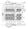
(イメージセンサ4の構成)
次に、イメージセンサ4について説明する。図2はイメージセンサ4の構成を示すブロック図である。同図に示すように、イメージセンサ4は、画素アレイ21、行制御部23、第1の列制御部25、第2の列制御部26、第1の列信号処理部27、及び第2の列信号処理部28を備えている。これらのうち、第1の列制御部25、第2の列制御部26、第1の列信号処理部27、及び第2の列信号処理部28が画素混合部を構成している。
(Configuration of image sensor 4)
Next, the image sensor 4 will be described. FIG. 2 is a block diagram showing the configuration of the image sensor 4. As shown in the figure, the image sensor 4 includes a
画素アレイ21は、行列状に配置された複数の画素22を含んでいる。詳しくは、この画素アレイ21では、2n+1ライン目の画素22を2nライン目の画素22に対して1/2画素分重心をずらして配置している。
The
行制御部23は、画素アレイ21の各画素22に対して露光及び行方向の読み出し制御を行う。
The
第1の列信号処理部27は、2m列目(mは、0以上の整数)の画素22によって撮像された撮像信号を処理する。また、第2の列信号処理部28は、2m+1列目の画素22によって撮像された撮像信号を処理する。列信号処理部27,28は、図3に示すように、A/D変換部31とフリップフロップ32を備えている(図中ではそれぞれA/D、FFと略記)。これにより、第1の列信号処理部27では、2n+1行目の画素22から読み出されたアナログの撮像信号をA/D変換部31でデジタル信号に変換した後、フリップフロップ32でラッチする。また、第2の列信号処理部28では、2n行目の画素22から読み出されたアナログの撮像信号を図3のA/D変換部31でデジタル信号に変換した後、フリップフロップ32でラッチする。
The first column
第1の列信号処理部27と第2の列信号処理部28には、それぞれ、第1の列制御部25と第2の列制御部26が接続されている。第1の列制御部25と第2の列制御部26においては、列方向の読み出し制御を行って、撮像された信号としてイメージセンサ4より出力する。
A first
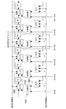
第1の列制御部25は、例えば図4のように構成することができる。この例では第1の列制御部25は、セレクタ41、加算器42、セレクタ43、フリップフロップ(図中ではFFと略記)、セレクタ45、及びフリップフロップ46を、接続された各第1の列信号処理部27に対応して備えている。同様に、第2の列制御部26は、例えば図5のように構成できる。この例では第2の列制御部26は、フリップフロップ51(図中ではFFと略記)、加算器52、セレクタ53、セレクタ54、フリップフロップ55(図中ではFFと略記)を接続された各第2の列信号処理部28に対応して備えている。
The first
(イメージセンサ4のカラーフィルタ)
次に、本実施形態のイメージセンサ4の画素22に配置されているカラーフィルタについて説明する。
(Color filter of image sensor 4)
Next, the color filter disposed in the
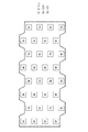
図7は、本実施形態のイメージセンサ4の画素22に配置されているカラーフィルタを説明する図である。このカラーフィルタは、単位配列71の繰り返しパターンで構成されている。
FIG. 7 is a diagram for explaining the color filter arranged in the
上述の、画素信号を混合しないで読み出す場合では、被写体からの入射光がそれぞれのカラーフィルタによって濾光され、画素22において光電変換された後、Mg(マゼンダ)、Cy(シアン)、Ye(イエロー)、Gr(グリーン)の画素信号として読み出されることになる。
In the case of reading without mixing pixel signals as described above, incident light from a subject is filtered by the respective color filters and subjected to photoelectric conversion in the
一方で、上述の、画素信号を混合して読み出す場合では、被写体からの入射光がそれぞれのカラーフィルタによって濾光され、画素22において光電変換された後、Mg(マゼンダ)、Cy(シアン)、Ye(イエロー)、Gr(グリーン)の画素信号となる。
On the other hand, in the case where the pixel signals are mixed and read out as described above, incident light from the subject is filtered by the respective color filters and subjected to photoelectric conversion in the
2n行目が全てGrの場合は、第1の列制御部25において、列方向にMgとGr、YeとCyが加算され、第2の列制御部26において、行方向にGrとGrが加算され、それぞれ、Mg+Gr、Ye+Cy、Gr+Grのように混合された画素信号が読み出される。
When all the 2nth rows are Gr, the first
2n+1行目が全てGrの場合は、第1の列制御部25において、列方向にGrとGrが加算され、第2の列制御部26において、行方向にGrとYe、MgとCyが加算され、それぞれ、Gr+Gr、Gr+Ye、Mg+Cyのように混合された画素信号が読み出される。
When all the 2n + 1th rows are Gr, the first
《デジタルビデオカメラ1(撮像システム)の動作》
(全体の動作)
デジタルビデオカメラ1により撮影を行うと、被写体はレンズ3を通してイメージセンサ4に入光し、イメージセンサ4上の画素において光電変換され、撮像信号としてDSP5へ出力される。
<< Operation of Digital Video Camera 1 (Imaging System) >>
(Overall operation)
When shooting is performed with the
この撮像信号は、メモリコントローラ7を介して、SDRAM8に対して読み出しと書き込みが行われ、レベル検出部9、YC処理部10、圧縮処理部11、デジタル信号処理部12、記録媒体であるSDカード13、表示媒体であるLCD14に対して、信号の入出力が実現される。
This image pickup signal is read and written to the
レベル検出部9は、撮像信号のレベルを検出し、撮像信号のレベルをCPU6に通知する。
The
YC処理部10は、撮像信号に対して、フィルタリングや同時化等を行い、撮像信号をYC信号に変換する。
The
圧縮処理部11は、撮像信号、又はYC信号を、例えば静止画ならばJPEG、動画ならばH.264等のフォーマットに従いデータ量の圧縮を行う。
The
デジタル信号処理部12は、ズーム処理、傷補正、照明光色温度検出等のビデオカメラとしての動作に必要な信号処理を行う。
The digital
一方で、CPU6は、デジタルビデオカメラ1がユーザの期待する動作を実現するのに必要な制御信号を、イメージセンサ4、DSP5の各機能ブロックに対して出力する。
On the other hand, the
(イメージセンサ4の駆動と列制御部(25,26)の動作)
イメージセンサ4が映像信号を上記のように出力する際の該イメージセンサ4の駆動方法について説明する。既述の通り、このイメージセンサ4には、画素信号を混合しない読出し動作と、画素信号を混合して読み出す動作の2種類の動作がある。
(Drive of image sensor 4 and operation of column control unit (25, 26))
A method of driving the image sensor 4 when the image sensor 4 outputs the video signal as described above will be described. As described above, the image sensor 4 has two types of operations, that is, a reading operation in which pixel signals are not mixed and an operation in which pixel signals are mixed and read.
−画素信号を混合しないで読み出し動作−
まず、画素信号を混合しないで読み出す場合について説明する。
-Read operation without mixing pixel signals-
First, a case of reading without mixing pixel signals will be described.
画素22において所定の露光時間分の露光が完了すると、行制御部23から2n+1行目の画素22に対して撮像信号の読み出しを行うための行選択信号が出力される。これにより、行選択信号により、2n+1行目の画素22に蓄積されている撮像信号が読み出されることが決定される。さらに、第1の列制御部25が列選択信号を出力することで、2n+1行目の画素22の撮像信号が第1の列信号処理部27に出力される。
When the exposure for a predetermined exposure time is completed in the
第1の列信号処理部27では、2n+1行目の画素22から読み出されたアナログの撮像信号をA/D変換部31でデジタル信号に変換した後、フリップフロップ32でラッチする。
In the first column
2n+1行目の画素22から読み出されてデジタル化された撮像信号は、イメージセンサ4の出力信号として出力するために、第1の列制御部25において転送される。
The image signal read out and digitized from the
その際、セレクタ41の出力が常に0の値を選択するように選択制御信号が入力されることで、加算器42の入力の片方が常に0になる。これにより、着目している列以外との画素信号との加算が行われなくなり、4m列目の画素信号のみがセレクタ43、4m+2列目の画素信号のみがセレクタ45に入力されるようになる。
At this time, a selection control signal is input so that the output of the
水平帰線期間毎に、加算器42の出力と4m+2列目からの出力が、それぞれセレクタ43とセレクタ45の出力になるように、セレクタ43とセレクタ45の選択制御信号を所定の期間制御することで、4m列目の画素信号と4m+2列目の画素信号が、フリップフロップとフリップフロップ46に入力される。
Control the selection control signals of the
その後、セレクタ43とセレクタ45の出力がフリップフロップ46とフリップフロップの出力になるように制御選択信号を制御することで、それぞれのフリップフロップがシーケンシャルに結合された状態となり、クロック印加によってシフト動作を行うことで、2m列の画素信号を読み出すことができる。
Thereafter, by controlling the control selection signal so that the outputs of the
この動作と並行して、行制御部23から2n行目の画素22に対して撮像信号の読み出しを行うための行選択信号が出力される。行選択信号により、2n行目の画素22に蓄積されている撮像信号が読み出されることが決定される。
In parallel with this operation, the
さらに、第2の列制御部26が列選択信号を出力することで、2n行目の画素22の撮像信号が第2の列信号処理部28に出力される。第2の列信号処理部28では、2n行目の画素22から読み出されたアナログの撮像信号を図3のA/D変換部31でデジタル信号に変換した後、フリップフロップ32でラッチする。
Further, the second
2n行目の画素22から読み出されたデジタル化された撮像信号は、イメージセンサ4の出力信号として出力するために、図5に示される第2の列制御部26において転送される。その際、セレクタ53の出力が常に0の値を選択する選択制御信号が入力されることで、加算器52の入力の片方が常に0になり、着目している画素信号以外との加算が行われなくなり、2m+1列目の画素信号がセレクタ54に入力されるようになる。
The digitized imaging signal read from the
水平帰線期間毎に、加算器52の出力が、セレクタ54の出力になるように、セレクタ54の選択制御信号を所定の期間制御することで、2m+1列目の画素信号が、フリップフロップ55に入力される。
By controlling the selection control signal of the
その後、セレクタ54の出力がフリップフロップ55の出力になるように制御選択信号を制御することで、それぞれのフリップフロップがシーケンシャルに結合された状態となり、クロック印加によってシフト動作を行い、2m+1列の画素信号を読み出すことができる。
After that, by controlling the control selection signal so that the output of the
行制御部23から行選択信号が出力され、デジタル化された画素22の撮像信号がフリップフロップ32でラッチされるまでの動作を、水平帰線期間毎nをインクリメントしながらに繰り返すことで、各行の撮像信号が第1の列制御部25と第2の列制御部26に読み出され、第1の列制御部25と第2の列制御部26に上述の制御信号を印加することで、各行の撮像信号がイメージセンサ4から出力される。垂直帰線期間毎にnをリセットすることで、画素アレイ21上の撮像信号読み出しが実現される。
By repeating the operation until the row selection signal is output from the
−混合読出し動作−
次に、画素信号を混合して読み出す場合について説明する。
-Mixed read operation-
Next, a case where pixel signals are mixed and read will be described.
画素22において所定の露光時間分の露光が完了すると、行制御部23から2n+1行目の画素22に対して撮像信号の読み出しを行うための行選択信号が出力される。行選択信号により、2n+1行目の画素22に蓄積されている撮像信号が読み出されることが決定される。
When the exposure for a predetermined exposure time is completed in the
さらに、第1の列制御部25が列選択信号を出力することで、2n+1行目の画素22の撮像信号が第1の列信号処理部27に出力される。第1の列信号処理部27では、2n+1行目の画素22から読み出されたアナログの撮像信号を図3のA/D変換部31でデジタル信号に変換した後、フリップフロップ32でラッチする。
Further, the first
2n+1行目の画素22から読み出されたデジタル化された撮像信号は、イメージセンサ4の出力信号として出力するために、図4に示される第1の列制御部25において転送される。その際、セレクタ41の出力が常に4m+2列目の値を選択する選択制御信号が入力されることで、加算器42の入力の片方が常に4m+2列目の画素信号になり、着目している4m列目と4m+2列目の画素信号の加算が行われ、画素信号の加算結果がセレクタ43に入力されるようになる。
The digitized imaging signal read from the
水平帰線期間毎に、加算器42の出力が、それぞれセレクタ43の出力になるように、セレクタ43の選択制御信号を所定の期間制御することで、4m列目の画素信号と4m+2列目の画素信号の加算結果が、フリップフロップに入力される。
By controlling the selection control signal of the
その後、セレクタ43とセレクタ45の出力がセレクタ45とフリップフロップの出力になるように制御選択信号を制御することで、それぞれのフリップフロップがシーケンシャルに結合された状態となり、クロック印加によってシフト動作を行うことで、加算された画素信号を読み出すことができる。
Thereafter, by controlling the control selection signal so that the outputs of the
上記の駆動を行うことで、図6の画素混合形状61に示されるような形状の画素の混合を行うことが可能になる。図6において、重心を太線で結んで記載されている画素同士が画素混合される画素である。
By performing the above driving, it is possible to mix pixels having a shape as shown in the
この動作と並行して、行制御部23から2n行目の画素22に対して撮像信号の読み出しを行うための行選択信号が出力される。行選択信号により、2n行目の画素22に蓄積されている撮像信号が読み出されることが決定される。
In parallel with this operation, the
さらに、第2の列制御部26が列選択信号を出力することで、2n行目の画素22の撮像信号が第2の列信号処理部28に出力される。第2の列信号処理部28では、2n行目の画素22から読み出されたアナログの撮像信号を図3のA/D変換部31でデジタル信号に変換した後、フリップフロップ32でラッチする。
Further, the second
2n行目の画素22から読み出されたデジタル化された撮像信号は、イメージセンサ4の出力信号として出力するために、図5に示される第2の列制御部26において転送される。その際、セレクタ53の出力が常に2n+2行目の画素信号に相当するフリップフロップ32の出力を選択する選択制御信号が入力されることで、加算器52の入力の片方が常にフリップフロップ32の出力信号になり、着目している2n行目と2n+2行目の画素信号の加算が行われ、画素信号の加算結果がセレクタ54に入力されるようになる。
The digitized imaging signal read from the
水平帰線期間毎に、加算器52の出力が、それぞれセレクタ54の出力になるように、セレクタ54の選択制御信号を所定の期間制御することで、2n行目の画素信号と2n+2行目の画素信号の加算結果が、フリップフロップ55に入力される。
By controlling the selection control signal of the
その後、セレクタ43の出力がフリップフロップ55の出力になるように制御選択信号を制御することで、それぞれのフリップフロップがシーケンシャルに結合された状態となり、クロック印加によってシフト動作を行うことで、加算された画素信号を読み出すことができる。
After that, by controlling the control selection signal so that the output of the
上記の駆動を行うことで、図6の画素混合形状62に示されるような形状の画素の混合を行うことが可能になり、行選択信号が選択するnの値を水平帰線期間毎にインクリメントし、垂直帰線期間毎にnをリセットすることで、画素アレイ21上の撮像信号読み出しが実現される。
By performing the above drive, it becomes possible to mix pixels having a shape as shown in the
以上のように、本実施形態によれば、水平方向の画素同士が画素混合された画素信号(行方向混合)と、垂直方向の画素同士が画素混合された画素信号(列方向混合)を得ることができる。このように混合によって得た画素信号は、列方向の混合では垂直方向のLPFの効果、行方向の混合では水平方向のLPF効果を加えたことと同じになり、それぞれの方向の解像度が低下することになる。しかしながら、本実施形態では、垂直方向にのみLPF効果が加えられた画素信号と、水平方向にのみLPF効果が加えられた画素信号の2種類の画素信号によって画素混合のパターンが構成されているので、水平方向又は垂直方向の何れかの画素信号によって、他方の欠落したエッジ情報を常に補完しあうことができる。これにより、このイメージセンサ4では、解像度の劣化を低減することが可能になる。従来は、LPF効果により欠落してしまった情報を復元するためには複雑な画像処理よりがその情報を補完していたが、本実施形態では上記の通り、エッジの情報を水平方向又は垂直方向の何れかの画素信号によって補完できるため、画像処理がよりの簡易化が可能になる。その結果、画素数の少ないイメージセンサでも高精細動画を得ることができる。 As described above, according to the present embodiment, a pixel signal in which horizontal pixels are mixed (row direction mixing) and a pixel signal in which vertical pixels are mixed (column direction mixing) are obtained. be able to. Thus, the pixel signal obtained by the mixing is the same as the effect of the vertical LPF in the mixing in the column direction and the horizontal LPF effect in the mixing in the row direction, and the resolution in each direction is lowered. It will be. However, in the present embodiment, the pixel mixture pattern is configured by two types of pixel signals: a pixel signal to which the LPF effect is applied only in the vertical direction and a pixel signal to which the LPF effect is applied only in the horizontal direction. The other missing edge information can always be complemented by either the horizontal or vertical pixel signal. As a result, the image sensor 4 can reduce resolution degradation. Conventionally, in order to restore information lost due to the LPF effect, the information is complemented by complicated image processing. However, in the present embodiment, as described above, the edge information is changed horizontally or vertically. Therefore, image processing can be further simplified. As a result, a high-definition moving image can be obtained even with an image sensor having a small number of pixels.
《実施形態1の変形例1》
上記においては、画素22に配置されているカラーフィルタの2n+1行目が全てGrであって、第2の列制御部26において、行方向にGrとYe、MgとCyが加算されるようにしたが、Ye+Mg、Gr+Cyのように混合される形態であってもよい。
<<
In the above, all the 2n + 1 rows of the color filters arranged in the
《実施形態1の変形例2》
上記においては、イメージセンサ4上の画素22に配置されているカラーフィルタを、図7のようにしたが、図8のような単位配列81をもつカラーフィルタ配列としてもよい。単位配列81に示されているGrはグリーンで、Cyはシアンで、Yeはイエローである。
<<
In the above, the color filter arranged in the
このようにすれば、画素を混合して読み出す場合、列方向に加算する行をGrのみで構成されている行を選択し、その他の行を行方向で加算することで、Gr+Gr、Ye+Ye、Cy+Cyとして画素信号が出力され、画素を混合しないで読み出す場合には、Gr、Cy、Yeとして画素信号が出力される。 In this way, when the pixels are mixed and read out, the row to be added in the column direction is selected as a row composed only of Gr, and the other rows are added in the row direction, so that Gr + Gr, Ye + Ye, Cy + Cy. When the pixel signal is output without mixing, the pixel signal is output as Gr, Cy, Ye.
《実施形態1の変形例3》
上記においては、イメージセンサ4上の画素22に配置されているカラーフィルタを、図7のようにしたが、図9のような単位配列91をもつカラーフィルタ配列としてもよい。単位配列81に示されているGrはグリーンで、Cyはシアンで、Yeはイエローである。
<<
In the above, the color filter arranged in the
このようにすれば、画素を混合して読み出す場合、行方向に加算する行をGrのみで構成されている行を選択し、その他の行を列方向で加算することで、Gr+Gr、Ye+Ye、Cy+Cyとして画素信号が出力され、画素を混合しないで読み出す場合には、Gr、Cy、Yeとして画素信号が出力される。 In this way, when the pixels are mixed and read out, a row composed only of Gr is selected as the row to be added in the row direction, and the other rows are added in the column direction, so that Gr + Gr, Ye + Ye, Cy + Cy. When the pixel signal is output without mixing, the pixel signal is output as Gr, Cy, Ye.
《実施形態1の変形例4》
上記においては、イメージセンサ4上の画素22に配置されているカラーフィルタを、図7のようにしたが、図10のような単位配列101をもつカラーフィルタ配列としてもよい。単位配列101に示されているGは緑で、Bは青で、Rは赤である。
<< Modification 4 of
In the above description, the color filter arranged in the
このようにすれば、画素を混合して読み出す場合、列方向に加算する行をGのみで構成されている行を選択し、その他の行を行方向で加算することで、G+G、G+R、G+Bとして画素信号が出力され、画素を混合しないで読み出す場合には、G、B、Rとして画素信号が出力される。 In this way, when the pixels are mixed and read, by selecting the row composed only of G as the row to be added in the column direction and adding the other rows in the row direction, G + G, G + R, G + B When the pixel signal is output without being mixed, the pixel signal is output as G, B, and R.
さらに、画素を混合して読み出す場合、行方向に加算する行をGのみで構成されている行を選択し、その他の行を列方向で加算することで、G+G、G+R、G+Bとして画素信号が出力され、画素を混合しないで読み出す場合には、G、B、Rとして画素信号が出力される。 Further, in the case where the pixels are mixed and read out, the pixel signal is expressed as G + G, G + R, and G + B by selecting the row composed only of G as the row to be added in the row direction and adding the other rows in the column direction. In the case of output and reading without mixing pixels, pixel signals are output as G, B, and R.
《実施形態1の変形例5》
上記においては、イメージセンサ4上の画素22に配置されているカラーフィルタを、図7のようにしたが、図11のような単位配列111をもつカラーフィルタ配列としてもよい。単位配列111に示されているGは緑で、Bは青で、Rは赤である。
<<
In the above, the color filter arranged in the
このようにすれば、画素を混合して読み出す場合、列方向に加算する行をGのみで構成されている行を選択し、その他の行を行方向で加算することで、G+G、R+R、B+Bとして画素信号が出力され、画素を混合しないで読み出す場合には、G、B、Rとして画素信号が出力される。 In this way, when the pixels are mixed and read, by selecting the row composed only of G as the row to be added in the column direction and adding the other rows in the row direction, G + G, R + R, B + B When the pixel signal is output without being mixed, the pixel signal is output as G, B, and R.
《実施形態1の変形例6》
上記においては、イメージセンサ4上の画素22に配置されているカラーフィルタを、図7のようにしたが、図12のような単位配列121をもつカラーフィルタ配列としてもよい。単位配列121に示されているGは緑で、Bは青で、Rは赤である。
<<
In the above description, the color filter arranged in the
このようにすれば、画素を混合して読み出す場合、行方向に加算する行をGのみで構成されている行を選択し、その他の行を列方向で加算することで、G+G、R+R、B+Bとして画素信号が出力され、画素を混合しないで読み出す場合には、G、B、Rとして画素信号が出力される。 In this way, when the pixels are mixed and read out, a row composed only of G is selected as a row to be added in the row direction, and the other rows are added in the column direction, so that G + G, R + R, B + B. When the pixel signal is output without being mixed, the pixel signal is output as G, B, and R.
《実施形態1の変形例7》
上記においては、イメージセンサ4上の画素22の画素信号を読み出す際に、連続的に全ての画素を読み出すように行選択信号、及び列選択信号を制御し、全ての列、及び全ての行の画素に対して混合を行った後に読み出しを行ったが、不連続的に画素を読み出すように行選択信号、或いは列選択信号を制御することで、画素アレイ21上の所定のアドレスの画素を読み出さない形態としてもよいし、所定の行や所定の列画素であってもよい。
<< Modification 7 of
In the above, when the pixel signal of the
《実施形態1の変形例8》
上記においては、イメージセンサ4上の画素22の画素信号を読み出す際の露光時間と読み出しを行うフレームレートについて指定を行わなかったが、列方向に画素を混合して読み出す画素信号と、行方向に画素を混合して読み出す画素信号の露光時間の長さが異なってもよいし、列方向に画素を混合して読み出す画素信号と、行方向に画素を混合して読み出す画素信号の読み出しを行う際のフレームレートが異なってもよい。
<<
In the above description, the exposure time when reading the pixel signal of the
《実施形態1の変形例9》
上記においては、撮像システムをデジタルビデオカメラとしたが、デジタルスチルカメラであってもよい。
<<
In the above description, the imaging system is a digital video camera, but it may be a digital still camera.
《発明の実施形態2》
本発明の実施形態2における撮像システムについて説明する。本発明の実施形態2における撮像システムは、本発明の実施形態1の一部の構成を変更したものであり、以下、当該相違点に着目して説明する。
<<
An imaging system according to
(イメージセンサの駆動と列制御部)
イメージセンサ4の駆動方法について説明する。
(Image sensor drive and column controller)
A method for driving the image sensor 4 will be described.
本実施形態は実施形態1に対し、画素信号を列方向に混合して読み出す場合についてのみ異なるので、ここでは、当該部分のみ説明する。
Since this embodiment is different from
画素22において所定の露光時間分の露光が完了すると、行制御部23から2n行目の画素22に対して撮像信号の読み出しを行うための行選択信号が出力される。行選択信号により、2n行目の画素22に蓄積されている撮像信号が読み出されることが決定される。
When exposure for a predetermined exposure time is completed in the
さらに、第2の列制御部26が4k+1列目の画素信号を読み出すための列選択信号を出力することで、2n行目4k+1列目の画素22の撮像信号が第2の列信号処理部28に出力される。第2の列信号処理部28では、2n行目4k+1列目の画素22から読み出されたアナログの撮像信号をA/D変換部31でデジタル信号に変換した後、フリップフロップ32でラッチする。
Further, the second
2n行目4k+1列目の画素22から読み出されたデジタル化された撮像信号は、イメージセンサ4の出力信号として出力するために、図5に示される第2の列制御部26において転送される。続いて、行制御部23から2n+2行目の画素22に対して撮像信号の読み出しを行うための行選択信号が出力される。行選択信号により、2n+2行目の画素22に蓄積されている撮像信号が読み出されることが決定される。
The digitized imaging signal read from the
この場合は、全ての列の画素22に蓄積されている撮像信号が読み出されるように、第2の列制御部26は列選択信号を出力することで、2n+2行目の画素22の撮像信号が第2の列信号処理部28に出力される。第2の列信号処理部28では、2n+2行目の画素22から読み出されたアナログの撮像信号を図3のA/D変換部31でデジタル信号に変換した後、フリップフロップ32でラッチする。
In this case, the second
その際、4k+1列目のセレクタ53の出力が常に2n+2行目の画素信号に相当するフリップフロップ32の出力を選択する選択制御信号が入力されることで、加算器52の入力の片方が常にフリップフロップ32の出力信号になり、着目している4k+1列目の2n行目と2n+2行目の画素信号の加算が行われる。そして、画素信号の加算結果がセレクタ54に入力されるようになり、4k+3列目の画素信号の混合の動作が行われるまでこの状態がホールドされる。
At that time, the selection control signal for selecting the output of the flip-
上述の4k+1列目のホールド状態と並行して、行制御部23から2n+4行目の画素22に対して撮像信号の読み出しを行うための行選択信号が出力される。
In parallel with the hold state of the 4k + 1 column, the
さらに、第2の列制御部26が4k+3列目の画素信号を読み出すための列選択信号を出力することで、2n行目4k+3列目の画素22の撮像信号が第2の列信号処理部28に出力される。第2の列信号処理部28では、2n+4行目4k+3列目の画素22から読み出されたアナログの撮像信号を図3のA/D変換部31でデジタル信号に変換した後、フリップフロップ32でラッチする。
Further, the second
その際、4k+3列目のセレクタ53の出力が常に2n+4行目の画素信号に相当するフリップフロップ32の出力を選択する選択制御信号が入力されることで、加算器52の入力の片方が常にフリップフロップ32の出力信号になり、着目している4k+3列目の2n+4行目と2n+2行目の画素信号の加算が行われ、画素信号の加算結果がセレクタ54に入力されるようになる。
At that time, the selection control signal for selecting the output of the flip-
この段階で、それぞれの加算器52から列毎に列方向に画素信号を加算した結果が出力されるようになり、4k+1列目は上述のホールド状態からイメージセンサ4からの画素信号読み出し動作のための状態に遷移する。
At this stage, the result of adding the pixel signals in the column direction is output from each
画素信号読み出し動作の状態に遷移した後、水平帰線期間毎に、加算器52の出力が、それぞれセレクタ54の出力になるように、セレクタ54の選択制御信号を所定の期間制御することで、4k+1列目の2n行目の画素信号と2n+2行目の画素信号の加算結果と4k+3列目の2n+2行目の画素信号と2n+4行目の画素信号の加算結果がフリップフロップ55に入力される。
After the transition to the pixel signal readout operation state, the selection control signal of the
その後、セレクタ43の出力がフリップフロップ55の出力になるように制御選択信号を制御することで、それぞれのフリップフロップがシーケンシャルに結合された状態となり、クロック印加によってシフト動作を行うことで、加算された画素信号を読み出すことができる。
After that, by controlling the control selection signal so that the output of the
上記の駆動を行うことで、図13の画素混合形状132に示されるような形状の画素の混合を行うことが可能になり、行選択信号が選択するnの値を水平帰線期間毎にインクリメントし、垂直帰線期間毎にnをリセットすることで、画素アレイ21上の撮像信号読み出しが実現される。
By performing the above drive, it becomes possible to mix pixels having a shape as shown in the
《実施形態2の変形例》
上記においては、イメージセンサ4上の画素22の画素信号を読み出す際に、列方向の画素信号の加算を行ったが、4k+1列目と4k+3列目の画素信号を加算する動作を、所定の垂直帰線期間毎に切り替える形態であってもよい。
<< Modification of
In the above description, when the pixel signals of the
《発明の実施形態3》
本発明の実施形態3における撮像システムについて説明する。本発明の実施形態3における撮像システムは、本発明の実施形態1の一部の構成を変更したものであり、以下、当該相違点に着目して説明する。
<<
An imaging system according to
−イメージセンサの駆動と列制御部−
イメージセンサ4の駆動方法について説明する。
-Image sensor drive and column controller-
A method for driving the image sensor 4 will be described.
本実施形態は実施形態1に対し、画素信号を列方向に混合して読み出す場合についてのみ異なるので、ここでは、当該部分のみ説明する。
Since this embodiment is different from
本実施形態においては、第1の列制御部25の構造と、その動作方法が異なっている。本実施形態の第1の列制御部25は、図14のように構成されている。この第1の列制御部は、セレクタ1441、加算器1442、セレクタ1443、及びフリップフロップ1444(図中ではFFと略記)を列毎に備えている。
In the present embodiment, the structure of the first
イメージセンサ4では、画素22において所定の露光時間分の露光が完了すると、行制御部23から2n+1行目の画素22に対して撮像信号の読み出しを行うための行選択信号が出力される。行選択信号により、2n+1行目の画素22に蓄積されている撮像信号が読み出されることが決定される。さらに、第1の列制御部25が列選択信号を出力することで、2n+1行目の画素22の撮像信号が第1の列信号処理部27に出力される。第1の列信号処理部27では、2n+1行目の画素22から読み出されたアナログの撮像信号をA/D変換部31でデジタル信号に変換した後、フリップフロップ32でラッチする。
In the image sensor 4, when exposure for a predetermined exposure time is completed in the
2n+1行目の画素22から読み出されたデジタル化された撮像信号は、イメージセンサ4の出力信号として出力するために、第1の列制御部25において転送される。その際、4m列目のセグメントのセレクタ11の出力が、常に4m+2列目の値を選択する選択制御信号が入力されることで、4m列目のセグメントの加算器12の入力の片方が常に4m+2列目の画素信号になり、着目している4m列目と4m+2列目の画素信号の加算が行われる。そして、4m列目のセグメントの加算器12の出力結果が4m列目のセグメントのセレクタ13に入力されるようになる。
The digitized imaging signal read from the
水平帰線期間毎に、4m列目のセグメントの加算器12の出力が、4m列目のセグメントのセレクタ13の出力になるように、4m列目のセグメントのセレクタ13の選択制御信号を所定の期間制御することで、4m列目の画素信号と4m+2列目の画素信号の加算結果が、4m列目のセグメントのフリップフロップ14に入力される。
For each horizontal blanking period, the selection control signal of the
その後、4m列目のセグメントのセレクタ13と4m+2列目のセグメントのセレクタ13の出力が、4m−2列目のセレクタ13と4m列目のセグメントのフリップフロップ14の出力になるように制御選択信号を制御することで、それぞれのフリップフロップがシーケンシャルに結合された状態となり、クロック印加によってシフト動作を行うことで、加算された画素信号を読み出すことができる。
After that, the control selection signal so that the outputs of the
上記の駆動を行うことで、図15の画素混合形状151に示されるような形状の画素の混合を行うことが可能になる。
By performing the above driving, it becomes possible to mix pixels having a shape as shown in the
つづいて、行制御部23から2n+3行目の画素22に対して撮像信号の読み出しを行うための行選択信号が出力される。行選択信号により、2n+3行目の画素22に蓄積されている撮像信号が読み出されることが決定される。
Subsequently, a row selection signal for reading an imaging signal is output from the
さらに、第1の列制御部25が列選択信号を出力することで、2n+3行目の画素22の撮像信号が第1の列信号処理部27に出力される。第1の列信号処理部27では、2n+3行目の画素22から読み出されたアナログの撮像信号を図3のA/D変換部31でデジタル信号に変換した後、フリップフロップ32でラッチする。
Further, when the first
2n+3行目の画素22から読み出されたデジタル化された撮像信号は、イメージセンサ4の出力信号として出力するために、第1の列制御部25において転送される。その際、4m+2列目のセグメントのセレクタ11の出力が、常に4m+4列目の値を選択する選択制御信号が入力されることで、4m+2列目のセグメントの加算器12の入力の片方が常に4m+4列目の画素信号になる。そして、着目している4m+2列目と4m+4列目の画素信号の加算が行われ、4m+2列目のセグメントの加算器12の出力結果が4m+2列目のセグメントのセレクタ13に入力されるようになる。
The digitized imaging signal read from the
水平帰線期間毎に、4m+2列目のセグメントの加算器12の出力が、4m+2列目のセグメントのセレクタ13の出力になるように、4m+2列目のセグメントのセレクタ13の選択制御信号を所定の期間制御することで、4m+2列目の画素信号と4m+4列目の画素信号の加算結果が、4m+2列目のセグメントのフリップフロップに入力される。
For each horizontal blanking period, the selection control signal of the
その後、4m列目のセグメントのセレクタ13と4m+2列目のセグメントのセレクタ13の出力が、4m+2列目のフリップフロップ16と4m列目のセグメントのセレクタ13の出力になるように制御選択信号を制御することで、それぞれのフリップフロップがシーケンシャルに結合された状態となり、クロック印加によってシフト動作を行うことで、加算された画素信号を読み出すことができる。
Thereafter, the control selection signal is controlled so that the outputs of the
上記の駆動を行うことで、図15の画素混合形状152に示されるような形状の画素の混合を行うことが可能になる。図15の画素混合形状151と152に示される形状の画素信号の加算を、所定の水平帰線期間毎に切り替わるように制御することで、図15に示されるような画素の混合の形状が実現される。
By performing the above driving, it becomes possible to mix pixels having a shape as shown in the
《実施形態3の変形例1》
上記においては、イメージセンサ4上の画素22の画素信号を読み出す際に、行方向の画素信号の加算を行ったが、2n+1行目と2n+3行目の画素信号を加算する動作を、図16に示すように入れ替えた形態であってもよいし、所定の垂直帰線期間毎に切り替える形態であってもよい。
<<
In the above description, the pixel signals in the row direction are added when reading out the pixel signals of the
《実施形態3の変形例2》
上記においては、行方向に画素を加算した結果の画素重心が画素ずらしの関係、又は、列方向に画素を加算した結果の画素重心が画素ずらしの関係となっていたが、上述の画素を混合する方法を組み合わせることで、図17に示すように、行方向に画素を加算した結果と列方向に画素を加算した結果の画素重心のそれぞれが画素ずらしの関係となるようにしてもよい。
<<
In the above, the pixel centroid resulting from adding the pixels in the row direction has a pixel shifting relationship, or the pixel centroid resulting from adding the pixels in the column direction has a pixel shifting relationship. By combining these methods, as shown in FIG. 17, the pixel centroids obtained as a result of adding pixels in the row direction and the result of adding pixels in the column direction may have a pixel shift relationship.
さらに、所定の垂直帰線期間毎、或いは、所定の水平帰線期間毎に、画素を混合する方法を組み合わせて画素を読み出してもよい。 Further, the pixels may be read out by combining the method of mixing the pixels every predetermined vertical blanking period or every predetermined horizontal blanking period.
《実施形態3の変形例3》
上記においては、行方向に画素を加算した結果の画素重心が画素ずらしの関係、又は、列方向に画素を加算した結果の画素重心が画素ずらしの関係となっていたが、上述の画素を混合する方法を組み合わせることで、図20に示すように、行方向に画素を加算した結果と列方向に画素を加算した結果の画素重心のそれぞれが一致する関係となるようにしてもよい。
<<
In the above, the pixel centroid resulting from adding the pixels in the row direction has a pixel shifting relationship, or the pixel centroid resulting from adding the pixels in the column direction has a pixel shifting relationship. By combining these methods, as shown in FIG. 20, the pixel centroids obtained by adding the pixels in the row direction and the pixel centroids obtained by adding the pixels in the column direction may be matched.
さらに、所定の垂直帰線期間毎、或いは、所定の水平帰線期間毎に、画素を混合する方法を組み合わせて画素を読み出してもよい。 Further, the pixels may be read out by combining the method of mixing the pixels every predetermined vertical blanking period or every predetermined horizontal blanking period.
《実施形態3の変形例4》
さらに、上記においては、混合する画素数を2として説明を行ったが、加算する回路を追加し駆動方法を制御することで3以上としてもよいし、行方向と列方向で画素信号を加算するそれぞれの画素の混合で、混合する画素の数が異なっていてもよい。
<< Modification 4 of
Furthermore, in the above description, the number of pixels to be mixed has been described as 2. However, it may be 3 or more by adding a circuit to be added and controlling the driving method, or adding pixel signals in the row direction and the column direction. The number of pixels to be mixed may be different depending on the mixing of the respective pixels.
さらに、列方向のみ画素信号を加算し、行方向は画素信号を加算しない、或いは列方向に画素信号を加算しないで行方向のみ画素信号を加算する形態であってもよい。 Furthermore, the pixel signals may be added only in the column direction, and the pixel signals may be added only in the row direction without adding the pixel signals in the column direction.
《実施形態3の変形例5》
さらに、上記においては、イメージセンサ4上の画素22に配置されているカラーフィルタを、図7のようにしたが、図19のようなカラーフィルタ配列としてもよい。図19に示されているGrはグリーンで、Cyはシアンで、Yeはイエローである。
<<
Furthermore, in the above description, the color filter arranged in the
このようにすれば、画素を混合して読み出す場合、列方向に加算する行をGrのみで構成されている行を選択し、その他の行を行方向で加算することで、Gr+Gr、Ye+Gr、Cy+Grとして画素信号が出力され、画素を混合しないで読み出す場合には、Gr、Cy、Yeとして画素信号が出力される。 In this way, when the pixels are mixed and read out, a row composed only of Gr is selected as the row to be added in the column direction, and the other rows are added in the row direction, so that Gr + Gr, Ye + Gr, Cy + Gr. When the pixel signal is output without mixing, the pixel signal is output as Gr, Cy, Ye.
また、列方向と行方向に加算する位置を入れ替えたものであってもよい。 Further, the positions to be added in the column direction and the row direction may be exchanged.
《実施形態3の変形例6》
さらに、上記においては、Grがカラーフィルタの過半数以上を占める配列で説明を行ったが、その他の色であってもよい。
<<
Furthermore, in the above description, Gr is described as an array that occupies a majority of color filters, but other colors may be used.
例えば、内視鏡等赤色成分が支配的な被写体向けのアプリケーション等においては、YeやR等が過半数を占める形態であってもよい。同様に、被写体において特定の色成分が支配的であるアプリケーションに対しては、その色成分の波長の光が透過しやすいカラーフィルタで構成する形態であるとよい。 For example, in an application for a subject in which a red component is dominant, such as an endoscope, Ye, R, or the like may occupy a majority. Similarly, for an application in which a specific color component is dominant in the subject, it may be configured with a color filter that easily transmits light of the wavelength of the color component.
《実施形態3の変形例7》
さらに、上記においては、Grがカラーフィルタの過半数以上を占める配列で説明を行ったが、全て同じ色のカラーフィルタのみで構成される画素アレイ21上の奇数列のみ、或いは、偶数列のみのカラーフィルタの色変調成分が、その他の偶数列、或いは、奇数列における同じ色のカラーフィルタと比較して低くし、全て同じ色のカラーフィルタのみで構成される画素アレイ21上の奇数列のみ、或いは偶数列のみのカラーフィルタから読み出される画素信号に被写体の輝度情報を多く含ませ、解像度と感度の向上をはかる形態であってもよい。より詳しくは、第2n列目(nは0又は正の整数)のカラーフィルタと第2n+1列目のカラーフィルタで、同一の色のカラーフィルタが配置されている画素において、第2n列目と第2n+1列目の何れかの前記同一の色の変調成分を、他方と比べ低くしたり、第2n列目の前記同一の色に対応するカラーフィルタの正規化された濾光特性における最大透過率と最小透過率の差と、第2n+1列目の何れかの前記同一の色に対応するカラーフィルタの正規化された濾光特性における最大透過率と最小透過率の差が異なるようにしたり、第2n列目の前記同一の色に対応するカラーフィルタの正規化された濾光特性における主たる波長以外の光に対する透過率と、第2n+1列目の何れかの前記同一の色に対応するカラーフィルタの正規化された濾光特性における主たる波長以外の光に対する透過率が異なるようにしたり、第2n列目の前記同一の色に対応するカラーフィルタの正規化された濾光特性における主たる波長の光に対する透過率の半値幅と、第2n+1列目の前記同一の色に対応するカラーフィルタの正規化された濾光特性における主たる波長の光に対する透過率の半値幅が異なるようにする。
<< Modification 7 of
Further, in the above description, Gr is described as an array in which more than half of the color filters occupy. However, only odd columns or only even columns on the
《実施形態3の変形例8》
さらに、上記においては、Grがカラーフィルタの過半数以上を占める配列で説明を行ったが、全て同じ色のカラーフィルタのみで構成される画素アレイ21上の奇数列のみ、或いは、偶数列のみのカラーフィルタを、画素22に入射する光の分光特性がほぼフラットになるグレーとしてもよいし、人間の輝度に対する分光感度の特性とほぼ同じにしてもよい。
<<
Further, in the above description, Gr is described as an array in which more than half of the color filters occupy. However, only odd columns or only even columns on the
なお、グレーのカラーフィルタは、可視光領域を撮影する場合であるならば、約400nmから約700nmの波長に対する分光特性が概ねフラットであればよく、赤外光領域や紫外光領域、又は、特定の波長の領域を撮影する場合であるならば、その波長の領域に対する分光特性が概ねフラットであればよい。 If the gray color filter is used for photographing the visible light region, the spectral characteristic with respect to a wavelength of about 400 nm to about 700 nm may be substantially flat, and the infrared light region, the ultraviolet light region, or the specific color filter may be used. If it is a case where the area | region of this wavelength is image | photographed, the spectral characteristic with respect to the area | region of the wavelength should just be substantially flat.
《発明の実施形態4》
本発明の実施形態3における撮像システムについて説明する。本発明の実施形態3における撮像システムは、本発明の実施形態3の一部の構成を変更したものであり、以下、当該相違点に着目して説明する。本実施形態においては、CPU6がイメージセンサ4における画素信号の混合画素数を制御するという点で異なっている。
<< Embodiment 4 of the Invention >>
An imaging system according to
本実施形態のCPU6は、撮像モジュール2やDSP5に配置されている各機能ブロックに対して、例えば、画素信号を混合して読み出すか画素信号を混合せずに読み出すかの切り替えや、YC処理部10における画像処理のパラメータ等を設定する。
The
本実施形態においては、レベル検出部9からの検出結果に応じて、CPU6は撮像モジュール2のTG(タイミングジェネレータ)(不図示)に対して、混合する画素信号の数を通知し、TGは、CPU6から通知された画素信号の混合数に基づいて、イメージセンサ4を駆動するための制御パルスを生成する。
In the present embodiment, the
図18は、本実施形態の撮像システムにおける、レベル検出部9の検知結果と画素信号の混合数の関係を示したものである。横軸は、レベル検出部9の検知結果であり、横軸の右側になるにつれて、イメージセンサ4から出力された撮像信号のレベルが大きい、すなわち、被写体の明るさが明るいことを示している。
FIG. 18 shows the relationship between the detection result of the
CPU6は、図18に示すように、被写体の明るさを複数の閾値で場合分けを行う。そして、第1の閾値よりレベル検出部9の検知結果が小さい場合は、6画素分の画素信号の混合を行い、レベル検出部9の検知結果が第1の閾値より大きく第2の閾値より小さい場合は、4画素分の画素信号の混合を行い、レベル検出部9の検知結果が第2の閾値より大きく第3の閾値より小さい場合は、2画素分の画素信号の混合を行い、第3の閾値よりレベル検出部9の検知結果が大きい場合は、画素の混合を行わずに画素信号を読み出す。
As shown in FIG. 18, the
《実施形態4の変形例1》
上記においては、混合する画素信号の数を6、4、2、1画素としたが、その他の組み合わせであってもよい。さらに、混合する画素信号の数の組み合わせを4通りではなく、2通り以上とした形態であってもよい。
<<
In the above description, the number of pixel signals to be mixed is 6, 4, 2, 1 pixel, but other combinations may be used. Furthermore, the number of pixel signals to be mixed may be two or more, instead of four.
《実施形態4の変形例2》
上記においては、CPU6が混合する画素信号の数をレベル検出部9の結果にのみ基づいて決定していたが、外部入力15から直接指定された値に応じて決定される方式であってもよいし、外部入力15から指定された値とレベル検出部9の検出結果を組み合わせてもよいし、外部入力15から上記の閾値を設定する形態であってもよい。
<<
In the above description, the number of pixel signals to be mixed by the
《実施形態4の変形例3》
上記においては、混合する画素信号の数のみに言及したが、列方向に混合する画素数と行方向に混合する画素信号の数の制御を独立とする形態であってもよい。
<<
In the above description, only the number of pixel signals to be mixed is mentioned, but the number of pixels mixed in the column direction and the number of pixel signals mixed in the row direction may be controlled independently.
《その他の実施形態》
なお、上記の説明は本発明を限定する物ではなく、発明の範囲内で種々の変更が可能である。
<< Other Embodiments >>
The above description is not intended to limit the present invention, and various modifications can be made within the scope of the invention.
例えば、上記の説明においては、イメージセンサ4をCMOSセンサとして説明したが、CCDセンサであってもよいし、NMOSセンサであってもよい。 For example, in the above description, the image sensor 4 is described as a CMOS sensor, but it may be a CCD sensor or an NMOS sensor.
また、イメージセンサ4に配置されているカラーフィルタの単位配列は、上記に限らず上下左右反転であってもよいし、色成分の入れ替えを行ってもよい。 Further, the unit arrangement of the color filters arranged in the image sensor 4 is not limited to the above, and may be reversed up and down, left and right, or the color components may be exchanged.
また、画素信号の混合をデジタルで行う形態としたが、アナログ信号、或いは、電荷の形態で加算を行うために、イメージセンサ4上に画素信号の混合、或いは、平均を行うためのコンデンサを配置してもよいし、水平転送CCD、垂直転送CCD上等で画素信号の混合、加算、或いは、平均を行ってもよい。 In addition, the pixel signal is mixed digitally. However, in order to perform addition in the form of an analog signal or charge, a capacitor for mixing or averaging the pixel signals is arranged on the image sensor 4. Alternatively, pixel signals may be mixed, added, or averaged on a horizontal transfer CCD, a vertical transfer CCD, or the like.
また、撮像システをデジタルビデオカメラとして構成した例を説明したが、電子スチルカメラとして構成してもよい。 Moreover, although the example which comprised the imaging system as a digital video camera was demonstrated, you may comprise as an electronic still camera.
本発明に係る撮像装置は、解像度の向上と画像処理の簡易化が可能になり、画素数の少ないイメージセンサでも高精細動画を得ることができるという効果を有し、画素ずらし配置された多数個の画素を有し、画素を混合して読み出す撮像装置、それを用いた撮像モジュール、電子スチルカメラ、及び電子ムービーカメラ等として有用である。 The image pickup apparatus according to the present invention can improve resolution and simplify image processing, and has an effect that a high-definition moving image can be obtained even with an image sensor with a small number of pixels. It is useful as an image pickup apparatus having the above-mentioned pixels and reading out the mixed pixels, an image pickup module using the same, an electronic still camera, an electronic movie camera and the like.
1 デジタルビデオカメラ
2 撮像モジュール
3 レンズ
4 イメージセンサ(撮像装置)
5 DSP(デジタル信号処理回路)
9 レベル検出部
22 画素
25 第1の列制御部
26 第2の列制御部
27 第1の列信号処理部
28 第2の列信号処理部
1
5 DSP (digital signal processing circuit)
9
Claims (40)
前記画素混合部は、同一の列内の画素同士の画素信号を混合する第1の混合動作と、同一の行内の画素同士の画素信号を混合する第2の混合動作とを行うことを特徴とする撮像装置。 A plurality of pixels that output pixel signals obtained by photoelectrically converting incident light arranged in a matrix in which the arrangement in the row direction is shifted, and a pixel mixing unit that outputs pixel signals from pixels in a plurality of rows by pixel mixing An imaging device comprising:
The pixel mixing unit performs a first mixing operation of mixing pixel signals of pixels in the same column and a second mixing operation of mixing pixel signals of pixels in the same row. An imaging device.
前記画素混合部は、第1及び第2のそれぞれの混合動作において、互いに隣接した画素同士の画素信号を混合するように構成されていることを特徴とする撮像装置。 The imaging device according to claim 1.
The pixel mixing unit is configured to mix pixel signals of pixels adjacent to each other in each of the first and second mixing operations.
前記画素混合部は、前記第1の画素混合動作により形成された画素混合後の重心が、該画素混合形状に係る画素に対して隣の列において隣接する画素についての前記第1の画素混合動作により形成された画素混合後の重心と一致し、且つ前記第2の画素混合動作により形成された画素混合後の重心が、該画素混合形状に係る画素に対して隣の行において隣接する画素についての前記第2の画素混合動作により形成された画素混合後の重心と一致するように画素信号を混合することを特徴とする撮像装置。 The imaging device according to claim 1.
The pixel mixing unit is configured to perform the first pixel mixing operation with respect to a pixel in which a center of gravity after pixel mixing formed by the first pixel mixing operation is adjacent in a column adjacent to the pixel having the pixel mixing shape. For the pixels adjacent to each other in the adjacent row with respect to the pixels related to the pixel mixture shape, the center of gravity after the pixel mixture formed by the second pixel mixing operation coincides with the center of gravity after the pixel mixture formed by An image pickup apparatus that mixes pixel signals so as to coincide with a center of gravity after pixel mixing formed by the second pixel mixing operation.
前記画素混合部は、前記第1の画素混合動作により形成された画素混合後の重心が、該画素混合形状に係る画素に対して隣の列において隣接する画素についての前記第1の画素混合動作により形成された画素混合後の重心に対し所定画素数分列方向にずれ、且つ前記第2の画素混合動作により形成された画素混合後の重心が、該画素混合形状に係る画素に対して隣の行において隣接する画素についての前記第2の画素混合動作により形成された画素混合後の重心と一致するように画素信号を混合することを特徴とする撮像装置。 The imaging device according to claim 1.
The pixel mixing unit is configured to perform the first pixel mixing operation with respect to a pixel in which a center of gravity after pixel mixing formed by the first pixel mixing operation is adjacent in a column adjacent to the pixel having the pixel mixing shape. The center of gravity after pixel mixing formed by the second pixel mixing operation is adjacent to the pixel related to the pixel mixing shape. An image pickup apparatus that mixes pixel signals so as to coincide with the center of gravity after pixel mixing formed by the second pixel mixing operation for adjacent pixels in the row.
前記画素混合部は、前記第1の画素混合動作により形成された画素混合後の重心が、該画素混合形状に係る画素に対して隣の列において隣接する画素についての前記第1の画素混合動作により形成された画素混合後の重心と一致し、且つ前記第2の画素混合動作により形成された画素混合後の重心が、該画素混合形状に係る画素に対して隣の行において隣接する画素についての前記第2の画素混合動作により形成された画素混合後の重心に対し所定画素数分行方向にずれるように画素信号を混合することを特徴とする撮像装置。 The imaging device according to claim 1.
The pixel mixing unit is configured to perform the first pixel mixing operation with respect to a pixel in which a center of gravity after pixel mixing formed by the first pixel mixing operation is adjacent in a column adjacent to the pixel having the pixel mixing shape. For the pixels adjacent to each other in the adjacent row with respect to the pixels related to the pixel mixture shape, the center of gravity after the pixel mixture formed by the second pixel mixing operation coincides with the center of gravity after the pixel mixture formed by An image pickup apparatus that mixes pixel signals so as to deviate in a row direction by a predetermined number of pixels with respect to a center of gravity after pixel mixing formed by the second pixel mixing operation.
前記画素混合部は、前記第1の画素混合動作により形成された画素混合後の重心が、該画素混合形状に係る画素に対して隣の列において隣接する画素についての前記第1の画素混合動作により形成された画素混合後の重心に対し所定画素数分列方向にずれ、且つ前記第2の画素混合動作により形成された画素混合後の重心が、該画素混合形状に係る画素に対して隣の行において隣接する画素についての前記第2の画素混合動作により形成された画素混合後の重心に対し所定画素数分行方向にずれるように画素信号を混合することを特徴とする撮像装置。 The imaging device according to claim 1.
The pixel mixing unit is configured to perform the first pixel mixing operation with respect to a pixel in which a center of gravity after pixel mixing formed by the first pixel mixing operation is adjacent in a column adjacent to the pixel having the pixel mixing shape. The center of gravity after pixel mixing formed by the second pixel mixing operation is adjacent to the pixel related to the pixel mixing shape. An image pickup apparatus that mixes pixel signals so as to be shifted in a row direction by a predetermined number of pixels with respect to a center of gravity after pixel mixing formed by the second pixel mixing operation for adjacent pixels in the row.
前記列方向のずれは、前記第1の画素混合動作により形成されて列方向に並んだ2つの画素混合後の重心間の距離よりも小さいことを特徴とする撮像装置。 The imaging device according to claim 4.
The image pickup apparatus, wherein the shift in the column direction is smaller than a distance between the centers of gravity after mixing two pixels formed in the first pixel mixing operation and arranged in the column direction.
前記行方向のずれは、前記第2の画素混合動作により形成されて行方向に並んだ2つの画素混合後の重心間の距離よりも小さいことを特徴とする撮像装置。 The imaging device according to claim 5.
The image pickup apparatus characterized in that the shift in the row direction is smaller than the distance between the centers of gravity after mixing the two pixels formed in the second pixel mixing operation and arranged in the row direction.
前記列方向のずれは、前記第1の画素混合動作により形成されて列方向に並んだ2つの画素混合後の重心間の距離よりも小さく、
前記行方向のずれは、前記第2の画素混合動作により形成されて行方向に並んだ2つの画素混合後の重心間の距離よりも小さいことを特徴とする撮像装置。 The imaging device according to claim 6.
The shift in the column direction is smaller than the distance between the centroids after mixing two pixels formed in the first pixel mixing operation and arranged in the column direction,
The image pickup apparatus characterized in that the shift in the row direction is smaller than the distance between the centers of gravity after mixing the two pixels formed in the second pixel mixing operation and arranged in the row direction.
前記第1の画素混合動作と前記第2の画素混合動作のそれぞれにおいて混合される画素数は、同一であることを特徴とする撮像装置。 In any one imaging device in any one of Claims 1-9,
The number of pixels mixed in each of the first pixel mixing operation and the second pixel mixing operation is the same.
前記第1の画素混合動作と前記第2の画素混合動作のそれぞれにおいて混合される画素数は、互いに異なることを特徴とする撮像装置。 In any one imaging device in any one of Claims 1-9,
The number of pixels mixed in each of the first pixel mixing operation and the second pixel mixing operation is different from each other.
前記第1の画素混合動作と前記第2の画素混合動作のそれぞれにおいて混合される画素数は、それぞれ2であることを特徴とする撮像装置。 In any one imaging device in any one of Claims 1-9,
The number of pixels to be mixed in each of the first pixel mixing operation and the second pixel mixing operation is 2, respectively.
前記第1の画素混合動作により読み出される画素の垂直方向の画素重心は、所定の垂直帰線期間毎に異なることを特徴とする撮像装置。 The imaging apparatus according to any one of claims 1 to 12,
The imaging apparatus according to claim 1, wherein a pixel gravity center in a vertical direction of pixels read out by the first pixel mixing operation is different for each predetermined vertical blanking period.
前記第2の画素混合動作により読み出される画素の水平方向の画素重心は、所定の垂直帰線期間毎に異なることを特徴とする撮像装置。 The imaging apparatus according to any one of claims 1 to 12,
An image pickup apparatus, wherein a pixel centroid in a horizontal direction of pixels read out by the second pixel mixing operation is different for each predetermined vertical blanking period.
前記第1の画素混合動作、又は前記第2の画素混合動作において、所定の行、所定の列、又は所定に画素アドレスの画素の信号の読出しが間引かれることを特徴とする撮像装置。 The imaging apparatus according to any one of claims 1 to 14,
In the first pixel mixing operation or the second pixel mixing operation, readout of signals of pixels at predetermined rows, predetermined columns, or predetermined pixel addresses is thinned out.
各画素には、カラーフィルタが配置されていることを特徴とする撮像装置。 The imaging device according to any one of claims 1 to 15,
An image pickup apparatus, wherein a color filter is disposed in each pixel.
前記カラーフィルタは、赤、緑、及び青からなる原色フィルタで構成されていることを特徴とする撮像装置。 The imaging device according to claim 16, wherein
The image pickup apparatus, wherein the color filter is composed of primary color filters made of red, green, and blue.
前記カラーフィルタは、マゼンダ、グリーン、シアン、及びイエローのうちの少なくとも3種類以上からなる補色フィルタで構成されていることを特徴とする撮像装置。 The imaging device according to claim 16, wherein
The image pickup apparatus according to claim 1, wherein the color filter includes a complementary color filter including at least three kinds of magenta, green, cyan, and yellow.
第2n列目(nは0又は正の整数)のカラーフィルタと第2n+1列目のカラーフィルタで、同一の色のカラーフィルタが配置されている画素において、第2n列目と第2n+1列目の何れかの前記同一の色の変調成分は、他方と比べ低いこと、又は、
第2n列目の前記同一の色に対応するカラーフィルタの正規化された濾光特性における最大透過率と最小透過率の差と、第2n+1列目の何れかの前記同一の色に対応するカラーフィルタの正規化された濾光特性における最大透過率と最小透過率の差が異なること、又は、
第2n列目の前記同一の色に対応するカラーフィルタの正規化された濾光特性における主たる波長以外の光に対する透過率と、第2n+1列目の何れかの前記同一の色に対応するカラーフィルタの正規化された濾光特性における主たる波長以外の光に対する透過率が異なること、又は、
第2n列目の前記同一の色に対応するカラーフィルタの正規化された濾光特性における主たる波長の光に対する透過率の半値幅と、第2n+1列目の前記同一の色に対応するカラーフィルタの正規化された濾光特性における主たる波長の光に対する透過率の半値幅が異なることを特徴とする撮像装置。 The imaging device according to any one of claims 16 to 18,
In the second nth column (n is 0 or a positive integer) color filter and the second n + 1 column color filter, the pixels of the same color are arranged in the second nth column and the second n + 1 column. Any one of the same color modulation components is lower than the other, or
The difference between the maximum transmittance and the minimum transmittance in the normalized filtering characteristics of the color filter corresponding to the same color in the 2nth column, and the color corresponding to any of the same colors in the 2n + 1th column The difference between the maximum and minimum transmittance in the normalized filtering characteristics of the filter is different, or
The transmittance for light other than the main wavelength in the normalized filtering characteristics of the color filter corresponding to the same color in the 2nth column, and the color filter corresponding to the same color in any of the 2n + 1th columns The transmittance for light other than the main wavelength in the normalized filtering characteristics of is different, or
The half width of the transmittance for light of the main wavelength in the normalized filtering characteristics of the color filter corresponding to the same color in the 2nth column, and the color filter corresponding to the same color in the 2n + 1th column An imaging apparatus, wherein the half-value widths of transmittances with respect to light of main wavelengths in the normalized filtering characteristics are different.
前記カラーフィルタは、グレー色、又は輝度に対する視感度特性を有することを特徴とする撮像装置。 The imaging device according to any one of claims 16 to 19,
The color filter has a visibility characteristic with respect to gray color or luminance.
前記カラーフィルタは、4画素の単位配列の繰り返しからなり、
前記単位配列の第2nライン目(nは0又は正の整数)の基準画素は第1の色のカラーフィルタ、
前記単位配列の第2nライン目において、前記基準画素に第1の水平方向で隣接する画素は第1の色のカラーフィルタ、
前記単位配列の第2n+1ライン目において、前記基準画素と第1の水平方向に所定の画素分重心ずれた位置の画素は第2の色のカラーフィルタ、
前記単位配列の第2n+1ライン目において、前記基準画素と第1の水平方向に所定の画素分重心ずれた位置の画素に第1の水平方向で隣接する画素は第3の色のカラーフィルタがそれぞれ配置されていることを特徴とする撮像装置。 The imaging device according to any one of claims 16 to 20,
The color filter is composed of a repeating unit array of four pixels,
The reference pixel of the second nth line (n is 0 or a positive integer) of the unit array is a color filter of the first color,
In the second n-th line of the unit array, pixels adjacent to the reference pixel in the first horizontal direction are color filters of a first color,
In the 2n + 1 line of the unit array, pixels at positions shifted from the reference pixel by a predetermined pixel in the first horizontal direction are color filters of a second color,
In the 2n + 1th line of the unit array, the pixel adjacent to the reference pixel in the first horizontal direction in the first horizontal direction from the reference pixel in the first horizontal direction is a third color filter. An imaging device characterized by being arranged.
前記カラーフィルタは、8画素の単位配列の繰り返しからなり、
前記単位配列の第4nライン目(nは0又は正の整数)の基準画素は第1の色のカラーフィルタ、
前記単位配列の第4n+2ライン目において、前記基準画素と水平方向に同一画素重心をもつ画素は第1の色のカラーフィルタ、
前記単位配列の第4nライン目において、前記単位配列の基準画素に第1の水平方向で隣接する画素は第1の色のカラーフィルタ、
前記単位配列の第4n+2ライン目において、前記基準画素に第1の水平方向で隣接する画素と水平方向に同一画素重心をもつ画素は第1の色のカラーフィルタ、
前記単位配列の第4n+1ライン目において、前記基準画素と第1の水平方向に所定の画素分重心ずれた位置の画素は第2の色のカラーフィルタ、
前記単位配列の第4n+3ライン目において、前記基準画素と第1の水平方向に所定の画素分重心ずれた位置の画素は第3の色のカラーフィルタ、
前記単位配列の第4n+1ライン目において、前記基準画素と第1の水平方向に所定の画素分重心ずれた位置の画素に第1の水平方向で隣接する画素は第2の色のカラーフィルタ、
前記単位配列の第4n+3ライン目において、前記基準画素と第1の水平方向に所定の画素分重心ずれた位置の画素に第1の水平方向で隣接する画素は第3の色のカラーフィルタがそれぞれ配置されていることを特徴とする撮像装置。 The imaging device according to any one of claims 16 to 20,
The color filter is composed of a repeating unit array of 8 pixels,
The reference pixel of the fourth nth line (n is 0 or a positive integer) of the unit array is a color filter of the first color,
In the fourth n + 2 line of the unit array, a pixel having the same pixel centroid in the horizontal direction as the reference pixel is a color filter of a first color,
In the fourth nth line of the unit array, pixels adjacent to the reference pixel of the unit array in the first horizontal direction are color filters of a first color,
In the fourth n + 2 line of the unit array, a pixel having the same pixel centroid in the horizontal direction as a pixel adjacent to the reference pixel in the first horizontal direction is a color filter of the first color,
In the 4n + 1th line of the unit array, the pixel at a position shifted by a predetermined center of gravity in the first horizontal direction from the reference pixel is a color filter of a second color,
In the fourth n + 3 line of the unit array, a pixel at a position shifted by a predetermined pixel center of gravity in the first horizontal direction from the reference pixel is a color filter of a third color,
In the fourth n + 1 line of the unit array, pixels adjacent to the reference pixel in the first horizontal direction in the first horizontal direction from the reference pixel in the first horizontal direction are pixels of the second color,
In the fourth n + 3 line of the unit array, pixels adjacent to the reference pixel in the first horizontal direction in the first horizontal direction from the reference pixel in the first horizontal direction are color filters of the third color, respectively. An imaging device characterized by being arranged.
前記カラーフィルタは、16画素の単位配列の繰り返しからなり、
前記単位配列の第8n列目(nは0以上の整数)の基準画素は、第1の色のカラーフィルタ、
前記単位配列の第8n+2列目において、前記基準画素と垂直方向に同一画素重心をもつ画素は第1の色のカラーフィルタ、
前記単位配列の第8n+4列目において、前記基準画素と垂直方向に同一画素重心をもつ画素は第1の色のカラーフィルタ、
前記単位配列の第8n+6列目において、前記基準画素と垂直方向に同一画素重心をもつ画素は第1の色のカラーフィルタ、
前記単位配列の第8n列目の基準画素に第1の垂直方向で隣接する画素は第1の色のカラーフィルタ、
前記単位配列の第8n+2列目において、前記基準画素と垂直方向に同一画素重心をもつ画素に第1の垂直方向で隣接する画素は第1の色のカラーフィルタ、
前記単位配列の第8n+4列目において、前記基準画素と垂直方向に同一画素重心をもつ画素に第1の垂直方向で隣接する画素は第1の色のカラーフィルタ、
前記単位配列の第8n+6列目において、前記基準画素と垂直方向に同一画素重心をもつ画素に第1の垂直方向で隣接する画素は第1の色のカラーフィルタ、
前記単位配列の第8n+1列目において、前記基準画素と第1の垂直方向に所定の画素分重心ずれた位置の画素は第2の色のカラーフィルタ、
前記単位配列の第8n+3列目において、前記基準画素と第1の垂直方向に所定の画素分重心ずれた位置の画素は第3の色のカラーフィルタ、
前記単位配列の第8n+5列目において、前記基準画素と第1の垂直方向に所定の画素分重心ずれた位置の画素は第4の色のカラーフィルタ、
前記単位配列の第8n+7列目において、前記基準画素と第1の垂直方向に所定の画素分重心ずれた位置の画素は第5の色のカラーフィルタ、
前記単位配列の8n+1列目において、前記基準画素と第1の垂直方向に所定の画素分重心ずれた位置の画素に第1の垂直方向で隣接する画素は第4の色のカラーフィルタ、
前記単位配列の8n+3列目において、前記基準画素と第1の垂直方向に所定の画素分重心ずれた位置の画素に第1の垂直方向で隣接する画素は第5の色のカラーフィルタ、
前記単位配列の8n+5列目において、前記基準画素と第1の垂直方向に所定の画素分重心ずれた位置の画素に第1の垂直方向で隣接する画素は第2の色のカラーフィルタ、
前記単位配列の8n+7列目において、前記基準画素と第1の垂直方向に所定の画素分重心ずれた位置の画素に第1の垂直方向で隣接する画素は第3の色のカラーフィルタがそれぞれ配置されていることを特徴とする撮像装置。 The imaging device according to any one of claims 16 to 20,
The color filter comprises a repetition of a unit array of 16 pixels,
The reference pixel in the 8th column (n is an integer of 0 or more) of the unit array is a color filter of the first color,
In the 8n + 2 column of the unit array, pixels having the same pixel centroid in the vertical direction as the reference pixel are color filters of the first color,
In the 8n + 4th column of the unit array, pixels having the same pixel centroid in the vertical direction to the reference pixel are color filters of the first color,
In the 8n + 6th column of the unit array, pixels having the same pixel centroid in the vertical direction as the reference pixel are color filters of the first color,
A pixel adjacent in the first vertical direction to the reference pixel in the eighth nth column of the unit array is a color filter of the first color,
In the 8n + 2th column of the unit array, pixels adjacent in the first vertical direction to pixels having the same pixel centroid in the vertical direction as the reference pixel are color filters of the first color,
In the 8n + 4th column of the unit array, pixels adjacent in the first vertical direction to pixels having the same pixel centroid in the vertical direction as the reference pixel are color filters of the first color,
In the 8n + 6th column of the unit array, a pixel adjacent in the first vertical direction to a pixel having the same pixel centroid in the vertical direction as the reference pixel is a color filter of the first color,
In the 8n + 1th column of the unit array, a pixel at a position shifted by a predetermined pixel center of gravity in the first vertical direction from the reference pixel is a color filter of a second color,
In the 8n + 3th column of the unit array, a pixel at a position shifted by a predetermined pixel center of gravity in the first vertical direction from the reference pixel is a color filter of a third color,
In the 8n + 5th column of the unit array, a pixel at a position shifted by a predetermined pixel center of gravity in the first vertical direction from the reference pixel is a color filter of a fourth color,
In the 8n + 7th column of the unit array, a pixel at a position shifted by a predetermined pixel center of gravity in the first vertical direction from the reference pixel is a color filter of a fifth color,
In the 8n + 1th column of the unit array, pixels adjacent to the reference pixel in the first vertical direction in the first vertical direction from the reference pixel in the first vertical direction are pixels of the fourth color,
In the 8n + 3 column of the unit array, pixels adjacent to the reference pixel in the first vertical direction by a predetermined pixel in the first vertical direction are pixels of the fifth color,
In the 8n + 5th column of the unit array, pixels adjacent to the reference pixel in the first vertical direction in the first vertical direction from the reference pixel in the first vertical direction are pixels of the second color,
In the 8n + 7th column of the unit array, a color filter of the third color is arranged in each pixel adjacent to the reference pixel in the first vertical direction at a position shifted by the predetermined center of gravity in the first vertical direction. An imaging apparatus characterized by being configured.
前記カラーフィルタは、16画素の単位配列の繰り返しからなり、
前記単位配列の第8nライン目(nは0以上の整数)の基準画素は、第1の色のカラーフィルタ、
前記単位配列の第8n+2ライン目において、前記基準画素と水平方向に同一画素重心をもつ画素は第1の色のカラーフィルタ、
前記単位配列の第8n+4ライン目において、前記基準画素と水平方向に同一画素重心をもつ画素は第1の色のカラーフィルタ、
前記単位配列の第8n+6ライン目において、前記基準画素と水平方向に同一画素重心をもつ画素は第1の色のカラーフィルタ、
前記単位配列の第8nライン目において、前記基準画素に第1の水平方向で隣接する画素は第1の色のカラーフィルタ、
前記単位配列の第8n+2ライン目において、前記基準画素に第1の水平方向で隣接する画素と水平方向に同一画素重心をもつ画素は第1の色のカラーフィルタ、
前記単位配列の第8n+4ライン目において、前記基準画素に第1の水平方向で隣接する画素と水平方向に同一画素重心をもつ画素は第1の色のカラーフィルタ、
前記単位配列の第8n+6ライン目において、前記基準画素に第1の水平方向で隣接する画素と水平方向に同一画素重心をもつ画素は第1の色のカラーフィルタ、
前記単位配列の第8n+1ライン目において、前記基準画素と第1の水平方向に所定の画素分重心ずれた位置の画素は第2の色のカラーフィルタ、
前記単位配列の第8n+3ライン目において、前記基準画素と第1の水平方向に所定の画素分重心ずれた位置の画素は第3の色のカラーフィルタ、
前記単位配列の第8n+5ライン目において、前記基準画素と第1の水平方向に所定の画素分重心ずれた位置の画素は第4の色のカラーフィルタ、
前記単位配列の第8n+7ライン目において、前記基準画素と第1の水平方向に所定の画素分重心ずれた位置の画素は第5の色のカラーフィルタ、
前記単位配列の第8n+1ライン目において、前記基準画素と第1の水平方向に所定の画素分重心ずれた位置の画素に第1の水平方向で隣接する画素は第4の色のカラーフィルタ、
前記単位配列の第8n+3ライン目において、前記基準画素と第1の水平方向に所定の画素分重心ずれた位置の画素に第1の水平方向で隣接する画素は第5の色のカラーフィルタ、
前記単位配列の第8n+5ライン目において、前記基準画素と第1の水平方向に所定の画素分重心ずれた位置の画素に第1の水平方向で隣接する画素は第2の色のカラーフィルタ、
前記単位配列の第8n+7ライン目において、前記基準画素と第1の水平方向に所定の画素分重心ずれた位置の画素に第1の水平方向で隣接する画素は第3の色のカラーフィルタがそれぞれ配置されていることを特徴とする撮像装置。 The imaging device according to any one of claims 16 to 20,
The color filter comprises a repetition of a unit array of 16 pixels,
The reference pixel of the eighth nth line (n is an integer of 0 or more) of the unit array is a color filter of the first color,
In the eighth n + 2 line of the unit array, pixels having the same pixel centroid in the horizontal direction as the reference pixel are color filters of the first color,
In the 8n + 4th line of the unit array, a pixel having the same pixel centroid in the horizontal direction as the reference pixel is a color filter of a first color,
In the 8n + 6th line of the unit array, a pixel having the same pixel centroid in the horizontal direction as the reference pixel is a color filter of the first color,
In the eighth n-th line of the unit array, pixels adjacent to the reference pixel in the first horizontal direction are color filters of a first color,
A pixel having the same pixel centroid in the horizontal direction as a pixel adjacent to the reference pixel in the first horizontal direction in the eighth n + 2 line of the unit array is a color filter of a first color,
In the 8n + 4th line of the unit array, a pixel having the same pixel centroid in the horizontal direction as a pixel adjacent to the reference pixel in the first horizontal direction is a color filter of the first color,
In the 8n + 6th line of the unit array, a pixel having the same pixel centroid in the horizontal direction as a pixel adjacent to the reference pixel in the first horizontal direction is a color filter of the first color,
In the 8n + 1th line of the unit array, a pixel at a position shifted from the reference pixel by a predetermined pixel in the first horizontal direction is a color filter of a second color,
In the 8n + 3th line of the unit array, a pixel at a position shifted from the reference pixel by a predetermined pixel in the first horizontal direction is a color filter of a third color,
In the 8n + 5th line of the unit array, a pixel at a position shifted by a predetermined pixel center of gravity in the first horizontal direction from the reference pixel is a color filter of a fourth color,
In the 8n + 7th line of the unit array, a pixel at a position shifted from the reference pixel by a predetermined pixel in the first horizontal direction is a color filter of a fifth color,
A pixel adjacent to the reference pixel in the first horizontal direction in the 8n + 1 line of the unit array in the first horizontal direction is a color filter of a fourth color.
In the 8n + 3rd line of the unit array, a pixel adjacent to the reference pixel in the first horizontal direction in the first horizontal direction is a color filter of a fifth color.
In the 8th + 5th line of the unit array, pixels adjacent to the reference pixel in the first horizontal direction in the first horizontal direction from the reference pixel in the first horizontal direction are pixels of the second color,
In the 8n + 7th line of the unit array, a pixel adjacent to the reference pixel in the first horizontal direction in the first horizontal direction is a third color filter for the pixel adjacent to the pixel in the first horizontal direction. An imaging device characterized by being arranged.
前記カラーフィルタは、第1の色がグリーン、第2の色がシアン、第3の色がイエローであることを特徴とする撮像装置。 The imaging device according to any one of claims 21 to 22,
The image pickup apparatus according to claim 1, wherein the first color is green, the second color is cyan, and the third color is yellow.
前記カラーフィルタは、第1の色が緑、第2の色が青、第3の色が赤であることを特徴とする撮像装置。 The imaging device according to any one of claims 21 to 22,
The image pickup apparatus according to claim 1, wherein the first color is green, the second color is blue, and the third color is red.
前記カラーフィルタは、第1の色がグリーン、第2の色がグリーン、第3の色がイエロー、第4の色がマゼンダ、第5の色がシアンであることを特徴とする撮像装置。 The imaging device according to any one of claims 23 to 24,
The image pickup device according to claim 1, wherein the first color is green, the second color is green, the third color is yellow, the fourth color is magenta, and the fifth color is cyan.
前記カラーフィルタは、第1の色が緑、第2の色が緑、第3の色が赤、第4の色が緑、第5の色が青であることを特徴とする撮像装置。 The imaging device according to any one of claims 23 to 24,
The image pickup device, wherein the first color is green, the second color is green, the third color is red, the fourth color is green, and the fifth color is blue.
前記第1の画素混合動作によって読み出された第1の読み出し画素信号と、前記第1の読み出し画素信号の画素に上下何れかの方向で隣接する画素から読出した第2の読み出し画素信号とを加算したカラーフィルタの色成分は、マゼンンダとシアンとグリーンとイエローが1:1:1:1の割合であることを特徴とする撮像装置。 The imaging device according to any one of claims 16 to 20,
A first readout pixel signal read out by the first pixel mixing operation and a second readout pixel signal read out from a pixel adjacent to the pixel of the first readout pixel signal in either the upper or lower direction. The color component of the added color filter has a ratio of 1: 1: 1: 1 for magenta, cyan, green, and yellow.
前記第1の画素混合動作によって読み出された第1の読み出し画素信号と、前記第2の画素混合動作によって読み出された第2の読み出し画素信号とを加算したカラーフィルタの色成分は、緑と赤と青が1:2:1の割合であることを特徴とする撮像装置。 The imaging device according to any one of claims 16 to 20,
The color component of the color filter obtained by adding the first read pixel signal read by the first pixel mixing operation and the second read pixel signal read by the second pixel mixing operation is green. And red and blue in a ratio of 1: 2: 1.
前記第1の画素混合動作によって読み出された第1の読み出し画素信号と、前記第2の画素混合動作によって読み出された第2の読み出し画素信号とを加算したカラーフィルタの色の割合は、全ての前記第1の画素混合動作によって読み出される信号において同じであることを特徴とする撮像装置。 The imaging device according to any one of claims 16 to 20,
The color ratio of the color filter obtained by adding the first read pixel signal read by the first pixel mixing operation and the second read pixel signal read by the second pixel mixing operation is: An imaging apparatus characterized in that the same signal is read in all the first pixel mixing operations.
前記第2の画素混合動作によって読み出された第3の読み出し画素信号と、前記第3の読み出し画素信号の画素に左右何れかの方向で隣接する画素からの第4の読み出し画素信号とを加算したカラーフィルタの色成分は、マゼンンダとシアンとグリーンとイエローが1:1:1:1の割合であることを特徴とする撮像装置。 The imaging device according to any one of claims 16 to 20,
The third readout pixel signal read out by the second pixel mixing operation is added to the fourth readout pixel signal from a pixel adjacent to the pixel of the third readout pixel signal in either the left or right direction. The color component of the color filter has a ratio of 1: 1: 1: 1 for magenta, cyan, green, and yellow.
前記第2の画素混合動作によって読み出された第3の読み出し画素信号と、前記第3の読み出し画素信号の画素に左右何れかの方向で隣接する画素からの第4の読み出し画素信号とを加算したカラーフィルタの色成分は、緑と赤と青が1:2:1の割合であることを特徴とする撮像装置。 The imaging device according to any one of claims 16 to 20,
The third readout pixel signal read out by the second pixel mixing operation is added to the fourth readout pixel signal from a pixel adjacent to the pixel of the third readout pixel signal in either the left or right direction. The color component of the color filter has a ratio of green, red and blue of 1: 2: 1.
前記第2の画素混合動作によって読み出された第3の読み出し画素信号と、前記第3の読み出し画素信号の画素に左右何れかの方向で隣接する画素からの第4の読み出し画素信号とを加算したカラーフィルタの色の割合が、全ての前記第2の画素混合動作によって読み出される信号において同じであることを特徴とする撮像装置。 The imaging device according to any one of claims 16 to 20,
The third readout pixel signal read out by the second pixel mixing operation is added to the fourth readout pixel signal from a pixel adjacent to the pixel of the third readout pixel signal in either the left or right direction. An image pickup apparatus, wherein the color ratio of the color filter is the same in all signals read out by the second pixel mixing operation.
各画素は、CCD、CMOS、又はNMOSの何れかにより構成されていることを特徴とする撮像装置。 The imaging device according to any one of claims 1 to 34,
Each pixel is constituted by any one of CCD, CMOS, or NMOS.
各画素から読み出された画素信号のレベルを検知するレベル検出部をさらに備え、
前記画素混合部は、前記レベル検出部が検出した画素信号のレベルの大きさに応じて画素の混合数を切り替えることを特徴とする撮像装置。 36. The imaging device according to any one of claims 1 to 35,
A level detector for detecting the level of the pixel signal read from each pixel;
The image pickup apparatus, wherein the pixel mixing unit switches the number of mixed pixels in accordance with a level level of a pixel signal detected by the level detection unit.
前記画素混合部は、画素混合する画素数を外部から変更できるように構成されていることを特徴とする撮像装置。 36. The imaging device according to any one of claims 1 to 35,
The image pickup apparatus, wherein the pixel mixing unit is configured to be able to change the number of pixels to be mixed from the outside.
レンズと、
を備えたことを特徴とする撮像モジュール。 An imaging device according to any one of claims 1 to 37;
A lens,
An imaging module comprising:
前記撮像モジュールから出力された撮像信号を処理するデジタル信号処理回路と、
を備えたことを特徴とする電子スチルカメラ。 An imaging module according to claim 38;
A digital signal processing circuit for processing an imaging signal output from the imaging module;
An electronic still camera comprising:
前記撮像モジュールから出力された撮像信号を処理するデジタル信号処理回路と、
を備えたことを特徴とする電子ムービーカメラ。 An imaging module according to claim 38;
A digital signal processing circuit for processing an imaging signal output from the imaging module;
An electronic movie camera characterized by comprising:
Priority Applications (4)
| Application Number | Priority Date | Filing Date | Title |
|---|---|---|---|
| JP2008091815A JP2009246745A (en) | 2008-03-31 | 2008-03-31 | Image pickup apparatus, image pickup module, electronic still camera and electronic movie camera |
| PCT/JP2008/003120 WO2009122468A1 (en) | 2008-03-31 | 2008-10-30 | Imaging device, imaging module, electronic still camera, and electronic movie camera |
| CN2008801283547A CN101981917A (en) | 2008-03-31 | 2008-10-30 | Imaging device, imaging module, electronic still camera, and electronic movie camera |
| US12/880,551 US20100328485A1 (en) | 2008-03-31 | 2010-09-13 | Imaging device, imaging module, electronic still camera, and electronic movie camera |
Applications Claiming Priority (1)
| Application Number | Priority Date | Filing Date | Title |
|---|---|---|---|
| JP2008091815A JP2009246745A (en) | 2008-03-31 | 2008-03-31 | Image pickup apparatus, image pickup module, electronic still camera and electronic movie camera |
Publications (1)
| Publication Number | Publication Date |
|---|---|
| JP2009246745A true JP2009246745A (en) | 2009-10-22 |
Family
ID=41134889
Family Applications (1)
| Application Number | Title | Priority Date | Filing Date |
|---|---|---|---|
| JP2008091815A Withdrawn JP2009246745A (en) | 2008-03-31 | 2008-03-31 | Image pickup apparatus, image pickup module, electronic still camera and electronic movie camera |
Country Status (4)
| Country | Link |
|---|---|
| US (1) | US20100328485A1 (en) |
| JP (1) | JP2009246745A (en) |
| CN (1) | CN101981917A (en) |
| WO (1) | WO2009122468A1 (en) |
Cited By (4)
| Publication number | Priority date | Publication date | Assignee | Title |
|---|---|---|---|---|
| JP2009268079A (en) * | 2008-04-01 | 2009-11-12 | Fujifilm Corp | Imaging apparatus, and driving method thereof |
| WO2011061891A1 (en) * | 2009-11-20 | 2011-05-26 | パナソニック株式会社 | Imaging device |
| JP2012191482A (en) * | 2011-03-11 | 2012-10-04 | Sony Corp | Imaging apparatus, imaging display system and acquisition method of imaging signal |
| JP2013255078A (en) * | 2012-06-06 | 2013-12-19 | Nikon Corp | Imaging device and imaging apparatus |
Families Citing this family (35)
| Publication number | Priority date | Publication date | Assignee | Title |
|---|---|---|---|---|
| US10298834B2 (en) | 2006-12-01 | 2019-05-21 | Google Llc | Video refocusing |
| US8657200B2 (en) | 2011-06-20 | 2014-02-25 | Metrologic Instruments, Inc. | Indicia reading terminal with color frame processing |
| JP5496976B2 (en) * | 2011-09-21 | 2014-05-21 | 富士フイルム株式会社 | Imaging apparatus, imaging program, and imaging method |
| JP5634614B2 (en) * | 2011-09-29 | 2014-12-03 | 富士フイルム株式会社 | Imaging device and imaging apparatus |
| CN104303493A (en) | 2012-05-09 | 2015-01-21 | 莱特洛公司 | Optimization of optical systems for improved light field capture and manipulation |
| JP6039926B2 (en) * | 2012-06-12 | 2016-12-07 | キヤノン株式会社 | Radiographic apparatus, control method of radiographic apparatus, and program |
| US9858649B2 (en) | 2015-09-30 | 2018-01-02 | Lytro, Inc. | Depth-based image blurring |
| CN104823442B (en) * | 2012-12-05 | 2018-03-30 | 松下知识产权经营株式会社 | Solid camera head |
| US10334151B2 (en) | 2013-04-22 | 2019-06-25 | Google Llc | Phase detection autofocus using subaperture images |
| US9711553B2 (en) * | 2014-04-28 | 2017-07-18 | Samsung Electronics Co., Ltd. | Image sensor including a pixel having photoelectric conversion elements and image processing device having the image sensor |
| JP6404923B2 (en) * | 2014-06-24 | 2018-10-17 | マクセル株式会社 | Imaging sensor and imaging apparatus |
| US10444931B2 (en) | 2017-05-09 | 2019-10-15 | Google Llc | Vantage generation and interactive playback |
| US10440407B2 (en) | 2017-05-09 | 2019-10-08 | Google Llc | Adaptive control for immersive experience delivery |
| US10341632B2 (en) | 2015-04-15 | 2019-07-02 | Google Llc. | Spatial random access enabled video system with a three-dimensional viewing volume |
| US10469873B2 (en) | 2015-04-15 | 2019-11-05 | Google Llc | Encoding and decoding virtual reality video |
| US11328446B2 (en) | 2015-04-15 | 2022-05-10 | Google Llc | Combining light-field data with active depth data for depth map generation |
| US10565734B2 (en) | 2015-04-15 | 2020-02-18 | Google Llc | Video capture, processing, calibration, computational fiber artifact removal, and light-field pipeline |
| US10567464B2 (en) | 2015-04-15 | 2020-02-18 | Google Llc | Video compression with adaptive view-dependent lighting removal |
| US10546424B2 (en) | 2015-04-15 | 2020-01-28 | Google Llc | Layered content delivery for virtual and augmented reality experiences |
| US10275898B1 (en) | 2015-04-15 | 2019-04-30 | Google Llc | Wedge-based light-field video capture |
| US10419737B2 (en) | 2015-04-15 | 2019-09-17 | Google Llc | Data structures and delivery methods for expediting virtual reality playback |
| US10540818B2 (en) | 2015-04-15 | 2020-01-21 | Google Llc | Stereo image generation and interactive playback |
| US10412373B2 (en) | 2015-04-15 | 2019-09-10 | Google Llc | Image capture for virtual reality displays |
| US9979909B2 (en) | 2015-07-24 | 2018-05-22 | Lytro, Inc. | Automatic lens flare detection and correction for light-field images |
| US10275892B2 (en) | 2016-06-09 | 2019-04-30 | Google Llc | Multi-view scene segmentation and propagation |
| US10679361B2 (en) | 2016-12-05 | 2020-06-09 | Google Llc | Multi-view rotoscope contour propagation |
| US10594945B2 (en) | 2017-04-03 | 2020-03-17 | Google Llc | Generating dolly zoom effect using light field image data |
| US10474227B2 (en) | 2017-05-09 | 2019-11-12 | Google Llc | Generation of virtual reality with 6 degrees of freedom from limited viewer data |
| US10354399B2 (en) | 2017-05-25 | 2019-07-16 | Google Llc | Multi-view back-projection to a light-field |
| US10545215B2 (en) | 2017-09-13 | 2020-01-28 | Google Llc | 4D camera tracking and optical stabilization |
| US10965862B2 (en) | 2018-01-18 | 2021-03-30 | Google Llc | Multi-camera navigation interface |
| JP7063199B2 (en) * | 2018-08-31 | 2022-05-09 | コニカミノルタ株式会社 | Radiation imaging system |
| CN114080795A (en) * | 2020-06-10 | 2022-02-22 | 深圳市汇顶科技股份有限公司 | Image sensor and electronic device |
| CN111988539B (en) * | 2020-07-27 | 2023-06-02 | 上海集成电路研发中心有限公司 | Infrared detector merging structure and merging method thereof |
| US11394934B2 (en) * | 2020-09-24 | 2022-07-19 | Qualcomm Incorporated | Binned anti-color pixel value generation |
Family Cites Families (7)
| Publication number | Priority date | Publication date | Assignee | Title |
|---|---|---|---|---|
| JP4423452B2 (en) * | 2000-12-27 | 2010-03-03 | 富士フイルム株式会社 | Solid-state imaging device |
| JP2003009166A (en) * | 2001-06-21 | 2003-01-10 | Fuji Film Microdevices Co Ltd | Imaging apparatus and its drive method |
| JP3877565B2 (en) * | 2001-10-04 | 2007-02-07 | 松下電器産業株式会社 | Imaging device |
| US7480000B2 (en) * | 2003-06-25 | 2009-01-20 | Fujifilm Corporation | Image-taking apparatus including a vertical transfer control device |
| JP2006157581A (en) * | 2004-11-30 | 2006-06-15 | Fuji Film Microdevices Co Ltd | Drive method of solid-state imaging element, and solid-state imaging apparatus |
| US7570290B2 (en) * | 2004-12-27 | 2009-08-04 | Sony Corporation | Drive method for solid-state imaging device, solid-state imaging device, and imaging apparatus |
| JP2006287464A (en) * | 2005-03-31 | 2006-10-19 | Fuji Photo Film Co Ltd | Solid state imaging device, and method of operating solid state imaging device |
-
2008
- 2008-03-31 JP JP2008091815A patent/JP2009246745A/en not_active Withdrawn
- 2008-10-30 CN CN2008801283547A patent/CN101981917A/en active Pending
- 2008-10-30 WO PCT/JP2008/003120 patent/WO2009122468A1/en active Application Filing
-
2010
- 2010-09-13 US US12/880,551 patent/US20100328485A1/en not_active Abandoned
Cited By (6)
| Publication number | Priority date | Publication date | Assignee | Title |
|---|---|---|---|---|
| JP2009268079A (en) * | 2008-04-01 | 2009-11-12 | Fujifilm Corp | Imaging apparatus, and driving method thereof |
| WO2011061891A1 (en) * | 2009-11-20 | 2011-05-26 | パナソニック株式会社 | Imaging device |
| JP2011109627A (en) * | 2009-11-20 | 2011-06-02 | Panasonic Corp | Imaging apparatus |
| US8698907B2 (en) | 2009-11-20 | 2014-04-15 | Panasonic Corporation | Image capture apparatus |
| JP2012191482A (en) * | 2011-03-11 | 2012-10-04 | Sony Corp | Imaging apparatus, imaging display system and acquisition method of imaging signal |
| JP2013255078A (en) * | 2012-06-06 | 2013-12-19 | Nikon Corp | Imaging device and imaging apparatus |
Also Published As
| Publication number | Publication date |
|---|---|
| US20100328485A1 (en) | 2010-12-30 |
| WO2009122468A1 (en) | 2009-10-08 |
| CN101981917A (en) | 2011-02-23 |
Similar Documents
| Publication | Publication Date | Title |
|---|---|---|
| WO2009122468A1 (en) | Imaging device, imaging module, electronic still camera, and electronic movie camera | |
| EP2311253B1 (en) | Image pickup apparatus and its control method | |
| TWI386049B (en) | A solid-state imaging device, and a device using the solid-state imaging device | |
| WO2009118799A1 (en) | Imaging device, imaging module and imaging system | |
| US20040046882A1 (en) | Electric camera | |
| JP5702896B2 (en) | Color imaging device and imaging apparatus | |
| JPH09247689A (en) | Color image pickup device | |
| JPH10336686A (en) | Image pickup device | |
| JP4905279B2 (en) | Imaging circuit and imaging apparatus | |
| WO2014007281A1 (en) | Colour imaging element and imaging device | |
| JP2005229603A (en) | Solid-state image-sensing device improved in display quality in sub-sampling mode, and its driving method | |
| JP2007243334A (en) | Imaging apparatus | |
| JP5621057B2 (en) | Color image sensor | |
| WO2010150433A1 (en) | Solid-state image pickup apparatus, image pickup module and image pickup system | |
| JP5033711B2 (en) | Imaging device and driving method of imaging device | |
| JP3902525B2 (en) | Image signal processing device | |
| JP2011066637A (en) | Solid-state imaging device and electronic apparatus | |
| EP2800376B1 (en) | Imaging device, method for controlling imaging device, and control program | |
| US20040263645A1 (en) | Sequential scan imaging device | |
| JP5411390B2 (en) | Color image sensor | |
| JP5624228B2 (en) | IMAGING DEVICE, IMAGING DEVICE CONTROL METHOD, AND CONTROL PROGRAM | |
| JP3909930B2 (en) | Single plate color solid-state imaging device | |
| US20220103766A1 (en) | Image sensing device and operating method thereof | |
| JP2000308071A (en) | Color image pickup element and color image pickup device | |
| JP2000032476A (en) | Image-pickup device |
Legal Events
| Date | Code | Title | Description |
|---|---|---|---|
| A621 | Written request for application examination |
Free format text: JAPANESE INTERMEDIATE CODE: A621 Effective date: 20100915 |
|
| RD02 | Notification of acceptance of power of attorney |
Free format text: JAPANESE INTERMEDIATE CODE: A7422 Effective date: 20120131 |
|
| A761 | Written withdrawal of application |
Free format text: JAPANESE INTERMEDIATE CODE: A761 Effective date: 20120312 |