JP2009244673A - Image forming apparatus - Google Patents
Image forming apparatus Download PDFInfo
- Publication number
- JP2009244673A JP2009244673A JP2008092320A JP2008092320A JP2009244673A JP 2009244673 A JP2009244673 A JP 2009244673A JP 2008092320 A JP2008092320 A JP 2008092320A JP 2008092320 A JP2008092320 A JP 2008092320A JP 2009244673 A JP2009244673 A JP 2009244673A
- Authority
- JP
- Japan
- Prior art keywords
- image forming
- frame
- forming apparatus
- intermediate frame
- image
- Prior art date
- Legal status (The legal status is an assumption and is not a legal conclusion. Google has not performed a legal analysis and makes no representation as to the accuracy of the status listed.)
- Granted
Links
Images


Landscapes
- Electrophotography Configuration And Component (AREA)
Abstract
Description
本発明は、装置本体に運搬用の取っ手が設けられてなる画像形成装置に関するものである。 The present invention relates to an image forming apparatus in which a handle for transportation is provided in an apparatus main body.
従来、特許文献1に記載されているような装置本体に運搬用の取っ手が設けられてなる画像形成装置が知られている。この画像形成装置は、用紙に画像形成処理を施す画像形成部が内装された装置本体部と、原稿からその画像を読み取るべくこの装置本体に積み重ねられた原稿処理部と、これら装置本体部と原稿処理部との間に介設された転写処理済みの用紙を受けるための胴内排紙部とを備えている。そして、前記取っ手は、棒体によって形成され、直方体状を呈した装置本体部のフレーム(以下、本体フレームという)の上部の4つの角部にそれぞれ出没自在に装着されている。 Conventionally, there is known an image forming apparatus in which a handle for transportation is provided on an apparatus main body as described in Patent Document 1. The image forming apparatus includes an apparatus main body unit in which an image forming unit that performs an image forming process on a sheet is provided, a document processing unit that is stacked on the apparatus main body so as to read the image from an original, the apparatus main unit, and the original And an in-body paper discharge unit for receiving the transfer-finished paper interposed between the processing unit and the processing unit. The handle is formed of a rod, and is attached to the four corners of the upper part of the frame (hereinafter referred to as a main body frame) of the apparatus main body having a rectangular parallelepiped shape so as to be able to appear and retract.
そして、かかる取っ手は、普段、本体フレーム内に没入されているが、画像形成装置を移動させるときには、本体フレームから引き出される。そして、この引き出された取っ手を把持して画像形成装置を運ぶことが行われる。 Such a handle is usually immersed in the main body frame, but is pulled out of the main body frame when the image forming apparatus is moved. Then, the image forming apparatus is carried by holding the pulled handle.
ところで、近年、画像形成装置のコンパクト化が進み、一人で抱えて持ち運ぶことができるようなサイズのものも出現している。このような小型の画像形成装置がフロア上に直置きされているような場合、取っ手の位置が可能な限り上方に位置している方が、腰を屈めなくてもよい分楽に運ぶことができ好ましい。このような観点で特許文献1の画像形成装置を見た場合、取っ手が本体フレームの最上部に設けられているため、それより下位に取っ手が向けられている場合に比較し運び易いのは確かであるが、装置本体のサイズによっては、これよりさらに上方に設けられる方が好ましい場合もある。 By the way, in recent years, image forming apparatuses have been made more compact, and those having a size that can be carried and carried by one person have appeared. When such a small image forming apparatus is placed directly on the floor, it is easier to carry the handle if the handle is positioned as high as possible without having to bend. preferable. When the image forming apparatus disclosed in Patent Document 1 is viewed from this point of view, the handle is provided at the uppermost part of the main body frame, so it is certainly easier to carry than when the handle is directed at a lower position. However, depending on the size of the apparatus main body, it may be preferable to provide it further upward.
そこで、取っ手を原稿処理部のフレームに設けることが考えられる。こうすることによって小型の画像形成装置がフロア上に直置きされているような場合でも、ほとんど腰を屈めることなく当該取っ手を介して画像形成装置をより容易に持ち運びすることができる。
しかしながら、画像形成装置の原稿処理部には、光源から照射した光で原稿面を走査し、その反射光を複数のミラーを介してCCD(Charge Coupled Device:撮像素子)へ入力するように構成された、光学的に原稿画像を読み取る画像読取装置が採用されている。この画像読取装置は、非常に繊細な精密機器であるため、原稿処理部のフレームに設けられた取っ手を介して画像形成装置を持ち運びする際に、当該フレームに僅かでも変形が生じると、この変形に起因して画像読取装置の構成機器が僅かに変位し、これによって反射光の光路に狂いが生じることから、正確な画像読取処理を行い得なくなるという不都合が生じる。 However, the document processing unit of the image forming apparatus is configured to scan the document surface with light emitted from a light source and input the reflected light to a CCD (Charge Coupled Device) through a plurality of mirrors. An image reading apparatus that optically reads an original image is employed. Since this image reading apparatus is a very delicate precision device, when the image forming apparatus is carried through a handle provided on the frame of the document processing unit and the frame is slightly deformed, As a result, the constituent devices of the image reading apparatus are slightly displaced, and this causes a deviation in the optical path of the reflected light, resulting in inconvenience that accurate image reading processing cannot be performed.
本発明は、従来のかかる不都合を解消するためになされたものであって、正確な画像読み取り処理を確保した上で装置本体を容易に持ち運びすることができる画像形成装置を提供することを目的としている。 SUMMARY OF THE INVENTION The present invention has been made in order to solve the conventional inconvenience, and it is an object of the present invention to provide an image forming apparatus capable of easily carrying the apparatus main body while ensuring accurate image reading processing. Yes.
請求項1記載の発明は、内部に画像形成処理を行う画像形成部が設けられる下部フレームと、この下部フレームの頂部に積み重ねられた状態で装着される中間フレームと、この中間フレームに支持された、原稿画像を光学的に読み取るための画像読取部が設けられてなる上部フレームとを有する装置本体が備えられ、前記中間フレームは、前記装置本体の側壁部位の一部を構成する一対の対向側面を有し、前記対向側面には、前記装置本体を持ち上げて運ぶための少なくとも一対の取っ手が設けられていることを特徴とする画像形成装置である。 According to the first aspect of the present invention, a lower frame in which an image forming unit for performing an image forming process is provided, an intermediate frame mounted in a stacked state on the top of the lower frame, and the intermediate frame supported by the lower frame. And an upper frame provided with an image reading unit for optically reading a document image, and the intermediate frame is a pair of opposed side surfaces constituting a part of a side wall portion of the apparatus main body. The image forming apparatus is characterized in that at least a pair of handles for lifting and carrying the apparatus main body is provided on the opposite side surface.
かかる構成によれば、下部フレームより上部に位置し、かつ、上部フレームを支持し得る中間フレームの対向側面に、画像形成装置を持ち運びするための取っ手が設けられているため、画像読取部の変形を防止して正確な画像読み取り処理を確保しつつ当該取っ手を介して画像形成装置の持ち運びを容易に行うことが可能になる。 According to such a configuration, the handle for carrying the image forming apparatus is provided on the opposite side surface of the intermediate frame that is located above the lower frame and can support the upper frame. Thus, it is possible to easily carry the image forming apparatus through the handle while ensuring accurate image reading processing.
請求項2記載の発明は、請求項1記載の発明において、前記取っ手は、前記中間フレームの壁面の一部が凹没されることによって形成された凹部または同一部が穿設されることによって形成された開口によって形成されていることを特徴とするものである。 According to a second aspect of the present invention, in the first aspect of the present invention, the handle is formed by forming a concave portion or the same portion formed by recessing a part of the wall surface of the intermediate frame. It is formed by the made opening.
かかる構成によれば、取っ手は、壁面に設けられた凹部または開口によって形成され手いるため、外部に突出した取っ手に比べて邪魔になるようなことがない。また、取っ手は、装置本体に対し出没可能に構成された従来の取っ手のように複雑な構造のものではなく、低コストで形成される。 According to such a configuration, the handle is formed by a recess or an opening provided on the wall surface, so that it does not get in the way compared to a handle protruding to the outside. In addition, the handle is not a complicated structure like a conventional handle configured to be able to appear and retract with respect to the apparatus main body, and is formed at a low cost.
請求項3記載の発明は、請求項1または2記載の発明において、前記中間フレームには、その上面に前記画像形成部でトナー画像が転写されて排出された転写材を受ける排出トレイが設けられていることを特徴とするものである。 According to a third aspect of the present invention, in the first or second aspect of the present invention, the intermediate frame is provided with a discharge tray on the upper surface thereof for receiving a transfer material discharged from the toner image transferred by the image forming unit. It is characterized by that.
かかる構成によれば、中間フレームの上面に排出トレイを設けることによって、当該中間フレームの中央部が凹没した状態になるとともに、周縁部が上部フレームを支持するための支持部となり、これらの凹凸で中間フレームは構造的に丈夫になるため、かかる中間フレームに支持された上部フレームは、変形することが有効に防止される。 According to such a configuration, by providing the discharge tray on the upper surface of the intermediate frame, the central portion of the intermediate frame is recessed, and the peripheral portion becomes a support portion for supporting the upper frame. Since the intermediate frame is structurally strong, deformation of the upper frame supported by the intermediate frame is effectively prevented.
請求項4記載の発明は、請求項1乃至3のいずれかに記載の発明において、前記中間フレームにおける前記取っ手が設けられた位置の近傍には、補強用のリブが設けられていることを特徴とするものである。 The invention according to claim 4 is the invention according to any one of claims 1 to 3, wherein a reinforcing rib is provided in the vicinity of the position where the handle is provided in the intermediate frame. It is what.
かかる構成によれば、中間フレームは、取っ手の近傍がリブによって構造的に補強された状態になるため、取っ手を介して手で画像形成装置を持ち上げたときの取っ手近傍での応力の集中に対抗し得るようになる。 According to such a configuration, the intermediate frame is in a state where the vicinity of the handle is structurally reinforced by the ribs, and therefore, it resists stress concentration in the vicinity of the handle when the image forming apparatus is lifted by hand through the handle. You can get it.
請求項5記載の発明は、請求項1乃至4のいずれかに記載の発明において、前記中間フレームの対向側面は、前記装置本体の全高の半分よりも高い位置にあることを特徴とするものである。 The invention according to claim 5 is the invention according to any one of claims 1 to 4, wherein the opposite side surface of the intermediate frame is located at a position higher than half of the total height of the apparatus main body. is there.
かかる構成によれば、取っ手を介して装置本体を持ち上げた状態で、その重心が取っ手より下に位置するため、持ち上げた状態が安定する。 According to such a configuration, since the center of gravity is located below the handle when the apparatus main body is lifted via the handle, the lifted state is stabilized.
本発明に係る画像形成装置によれば、下部フレームより上部に位置し、かつ、上部フレームを均等に支持し得る中間フレームに、画像形成装置を持ち運びするための取っ手が設けられているため、ユーザーは、当該画像形成装置を移動させるに際し、一々腰を屈めて画像形成装置を持ち上げるような不便なことを行うことなく、画像形成装置を容易に持ち運びすることができるばかりか、これによって画像読取部が変形するような不都合の発生を防止することができ、画像形成装置を移動させた後でも正確な画像読み取り処理を確保することができる。 According to the image forming apparatus of the present invention, the handle for carrying the image forming apparatus is provided in the intermediate frame that is located above the lower frame and can support the upper frame evenly. When the image forming apparatus is moved, the image forming apparatus can be easily carried without causing the inconvenience of bending the waist and lifting the image forming apparatus one by one. Can be prevented, and accurate image reading processing can be ensured even after the image forming apparatus is moved.
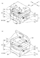
図1は、本発明に係る画像形成装置10の一実施形態を示す斜視図であり、図1(A)は、原稿押さえ部材22が閉じられた状態、図1(B)は、原稿押さえ部材22が開かれた状態をそれぞれ示している。また、図2は、図1に示す画像形成装置10の断面図であり、図2(A)は、図1(A)のIIA−IIA線断面図、図2(B)は、図1(A)のIIB−IIB線断面図である。また、図3は、画像形成装置10の装置本体11の一実施形態を示す分解斜視図であり、図4は、画像形成装置10を持ち上げる状態を説明するための画像形成装置10の一部切り欠き正面図である。なお、図1〜図4において、X−X方向を幅方向、Y−Y方向を前後方向といい、特に−X方向を左方、+X方向を右方、−Y方向を前方、+Y方向を後方という。
FIG. 1 is a perspective view showing an embodiment of an
これらの図に示すように、画像形成装置10は、原稿に形成された画像を読み取る原稿読取部20と、この原稿読取部20の下方に設けられた画像形成部30と、前記原稿読取部20の前方位置から前方に向かって突設された部分に設けられた操作部40と、画像形成部30により画像形成処理が施されることによって印刷された用紙Pが排紙される排紙部50とが筐体である装置本体11に装着されることによって基本構成されている。
As shown in these drawings, the
装置本体11は、図3に示すように、各種のフレームからなる本体フレーム12と、この本体フレーム12の外面を覆う複数枚の化粧板15とを備えている。
As shown in FIG. 3, the apparatus
本体フレーム12は、原稿読取部20および操作部40が装着される扁平な直方体状を呈した上部フレーム13と、画像形成部30が装着される下部フレーム14と、これら上部フレーム13および下部フレーム14間に介設される排紙部50を形成させるための中間フレーム60とからなっている。
The
化粧板15は、下部フレーム14の前面を覆う前面枠板16と、下部フレーム14および中間フレーム60の左右両側面を覆う左右方向一対の側面板17と、下部フレーム14の後面(背面)を覆う背面板18とからなっている。装置本体11は、これら前面枠板16、側面板17および背面板18が下部フレーム14に装着されることにより外嵌視が美麗になる。
The
前記原稿読取部20は、上部フレーム13の天板の中央部に矩形状で大きく場所取りされた上面開口131に嵌め込まれるコンタクトガラス21と、このコンタクトガラス21に載置された原稿P1を押さえるべく開閉される原稿押さえ部材22と、上部フレーム13に内装され、コンタクトガラス21上に載置された原稿P1の原稿面から原稿画像を光学的に読み取る光学系ユニット23とを備えている。
The
前記原稿押さえ部材22は、その後縁部が左右方向一対の蝶番部材132を介して上部フレーム13の後縁部上面に連結され、各蝶番軸132回りに正逆回動操作することにより、コンタクトガラス21を塞いだ閉止姿勢(図1(A))と、コンタクトガラス21を開放した開放姿勢(図1(B))との間で姿勢変更することができる。
The
そして、原稿P1の原稿画像を読み取るときは、原稿押さえ部材22を開いた状態で原稿面が密着するようにコンタクトガラス21上に当該原稿P1を載置し、その後、原稿押さえ部材22が閉じられた状態で光学系ユニット23により原稿画像が読み取られる。
When reading the document image of the document P1, the document P1 is placed on the
以下、図2(A)を基に光学系ユニット23について説明する。光学系ユニット23は、いわゆるCCD(charge coupled device)移動タイプと称されるものである。かかる光学系ユニット23は、左右方向へ移動する移動枠体230と、この移動枠体230に内装された照射ランプ231と、この照射ランプ231から照射された光の原稿面からの反射光をさらに反射させる複数枚の反射ミラー232と、これら反射ミラー232からの反射光を集光して焦点距離を調節するレンズユニット234と、このレンズユニット234から入光された光による画像情報を電気信号に変換するCCDイメージセンサ235とを備えている。
Hereinafter, the
照射ランプ231は、移動枠体230内の左右方向の中央位置より若干右寄りの位置の上部に設けられている。
The
反射ミラー232は、移動枠体230内の右半分の位置に設けられている。かかる反射ミラー232は、照射ランプ231が照射した光の原稿P1からの反射光を最初に受けて反射する第1ミラー232aと、この第1ミラー232aの反射光を受けて反射する第2ミラー232bと、この第2ミラー232bからの反射光をさらに反射させてレンズユニット234へ入光させる第3ミラー232cとの3枚が採用されている。第3ミラー232cは、特に凹面鏡によって形成され、その焦点位置にレンズユニット234が位置するように設置位置が設定されている。
The reflection mirror 232 is provided at the right half position in the
前記レンズユニット234は、移動枠体230の略中央位置に設けられているとともに、前記CCDイメージセンサ235は、移動枠体230内におけるレンズユニット234の直ぐ左側に設けられ、レンズユニット234で集光された光は、そのままCCDイメージセンサ235に向けて出力される。そして、レンズユニット234からの光が入光されたCCDイメージセンサ235は、当該光をその強弱に応じたアナログ量の電気信号に変換した後に引き続きデジタル量に変換し、所定の記憶装置を介して画像形成部30の後述する露光装置313へ向けて出力する。
The
かかる光学系ユニット23において、移動枠体230を移動させるための移動機構24が設けられている。この移動機構24は、上部フレーム13内の右端部の底板133上に据え付けられた駆動モータ241と、この駆動モータ241の駆動力が減速状態で伝達されるギヤ機構242と、このギヤ機構242を介して前記駆動モータ241の駆動力が伝達される駆動プーリ243と、底板133の左端位置で駆動プーリ243と対向配置された従動プーリ244と、この従動プーリ244および前記駆動プーリ243間に張設されたスキャナベルト245とを備えている。そして、前記スキャナベルト245の一部が光学系ユニット23の移動枠体230の適所に固定されている。
In the
かかる移動機構24によれば、駆動モータ241を正逆駆動させることにより、この駆動がギヤ機構242を介して減速状態で駆動プーリ243に伝達され、これによるスキャナベルト245の駆動プーリ243および従動プーリ244間の周回によって当該スキャナベルト245に固定された光学系ユニット23が正逆移動することになる。
According to the moving
従って、コンタクトガラス21上に載置された原稿P1の原稿面を読み取るときは、駆動モータ241の駆動によるスキャナベルト245の周回で移動枠体230が上部フレーム13内の左端部(ホームポジション)からの右方に向けて移動する。この移動によってされつつ、照射ランプ231からの光でコンタクトガラス21上の原稿P1の画像が走査され、当該走査による反射光がCCDイメージセンサ235に入力されて原稿画像が読み取られる。
Therefore, when reading the document surface of the document P1 placed on the
ついで、図2(B)を基に画像形成部30の概要を説明する。前記画像形成部30は、原稿読取部20で読み取られた原稿画像を用紙Pにトナー画像として転写する転写部31と、この転写部31で用紙Pへ転写されたトナー画像の当該用紙Pへの定着処理を施す定着部32と、前記転写部31に向けて給紙する用紙Pを貯留する用紙貯留部33とが箱形を呈した前記下部フレーム14に内装されることによって構成されている。
Next, the outline of the
前記転写部31は、周面に静電潜像およびトナー画像が順次形成される感光体ドラム311と、この感光体ドラム311の周面に一様な帯電処理を施す帯電器312と、この帯電器312によって一様に帯電された感光体ドラム311の周面にレーザー光を照射して当該周面に静電潜像を形成させる露光装置313と、この露光装置313によって形成された感光体ドラム311の周面の静電潜像にトナーを供給してトナー像を形成させる現像装置314とを備えている。
The
そして、軸心回りに回転しつつ帯電器312により一様に帯電された感光体ドラム311の周面には、前記光学系ユニット23での走査によって読み取られ、記憶装置に記憶されている原稿の画像情報に基づくレーザー光が露光装置313から照射され、これによって感光体ドラム311の周面に静電潜像が順次形成されるとともに、走査光照射位置の下流側で静電画像に現像装置314からトナーが供給されることにより感光体ドラム311の周面にトナー画像が形成される。この感光体ドラム311周面のトナー画像がレジストローラ対315を介して給紙された用紙Pに転写される。
Then, the peripheral surface of the photosensitive drum 311 that is uniformly charged by the charger 312 while rotating around the axis is read by scanning with the
前記定着部32は、転写部31で感光体ドラム311によりトナー画像の転写された用紙Pの転写画像に対し定着処理を施すものである。かかる定着部32は、内部にハロゲンランプ等の通電発熱体が内装された定着ローラ321と、下部でこの定着ローラ321に対向配置された加圧ローラ322とを有している。
The fixing
そして、前記転写部31から感光体ドラム311の駆動回転により搬送された用紙Pは、定着ローラ321および加圧ローラ322間に給紙され、ここでの定着ローラ321からの伝熱による加熱処理でトナー画像が用紙Pに定着される。定着部32を通過した用紙Pは、最下流端に設けられた搬出路34を通り、排紙口35から排紙部50へ向けて排紙されることになる。
The sheet P conveyed from the
前記用紙貯留部33は、下部フレーム14に対して挿脱自在に装着された用紙カセット331と、この用紙カセット331の一方の端部(図2(B)に示す例では前端部)に対応して設けられたピックアップローラ332とを備えている。このピックアップローラ332の駆動回転で用紙カセット331に装填されている用紙Pの束の最上位のものが順次繰り出され、転写部31に向けて給紙される。
The
そして、ピックアップローラ332を介して用紙カセット331から繰り出された用紙Pは、レジストローラ対315を介して搬送されつつ、感光体ドラム311の周面のトナー画像が転写され、引き続き定着部32で定着ローラ321による熱定着処理が施された後、搬出路34を通って排紙口35から排紙部50の排紙トレイ51に排紙される。
Then, the paper P fed out from the
また、下部フレーム14の前面位置には用紙手差し部36が設けられている。この用紙手差し部36は、開閉可能な手差しトレイ361と、開放状態の手差しトレイ361に載置された用紙Pを取り込んで転写部31へ向けて給紙するピックアップローラ362とを有している。
Further, a manual
前記操作部40は、図1に示すように、上部フレーム13の前縁部分が前方に向かって突設されることにより形成された操作部用筐体41と、この操作部用筐体41の上面に形成された操作パネル42とを備えている。操作パネル42には、スタートボタン43や、各種の操作ボタン44さらには各種の画像形成用の情報を画面表示するLCD(Liquid crystal display)からなるディスプレー45等の操作用の部材が設けられ、これらの操作用部材を操作したり視認したりすることによって具体的な画像形成処理が実行される。
As shown in FIG. 1, the
そして、本発明では、例えば上述のように構成された画像形成装置10において、取っ手64が中間フレーム60に設けられることにより、原稿読取部20による正確な画像読み取り処理を確保しながら、画像形成装置10の持ち運びを容易に行うことができるようにしている。
In the present invention, for example, in the
以下、中間フレーム60について図3を基に説明する、中間フレーム60は、図3に示すように、下部フレーム14に積み重ねられて固定される平面視で矩形状を呈した環状底板61と、この環状底板61の中央部に形成された胴内排紙トレイ(排出トレイ)62と、前記環状底板61の左右の板部(側方板部611)および胴内排紙トレイ62を囲うべく後方縁部612から立設された平面視でC字状を呈する囲い壁63と、この囲い壁63に設けられた左右一対の取っ手64とを備えている。
Hereinafter, the
胴内排紙トレイ62は、環状底板61の前縁部613から後方に向かって上に凸の円弧状で先下がりに形成されている。かかる胴内排紙トレイ62の左右の縁部と各側方板部611との間には、細長い三角形状の三角側壁621がそれぞれ設けられているとともに、胴内排紙トレイ62の後部と環状底板61の後方縁部612上の前方位置との間には、後部壁614が架設されている。この後部壁614の上下方向の略中央部には、左右方向に延びた、用紙Pを胴内排紙トレイ62上へ排出するための排紙口35が設けられている。
The in-
前記囲い壁63は、前方位置に左右方向に延びた広い隙間が確保された状態で胴内排紙トレイ62を囲繞するとともに、前記上部フレーム13を支持するためのものである。かかる囲い壁63は、前記左右の側方板部611の互いに離間した縁部から立設された前後方向へ延びる左右一対の側部壁631と、前記後方縁部612に支持された状態で各側部壁631の後縁部間に架設された後部壁632とからなっている。前記側部壁631は、装置本体11の側壁部位の一部を構成する一対の対向側面を有するものである。
The surrounding
前記各側部壁631の前縁部には、互いに対向方向へ寄った状態の門柱部633がそれぞれ設けられている。そして、一方の門柱部633の上端面、一方の側部壁631の上縁部、後部壁632の上縁部および他方の側部壁631の上縁部および他方の門柱部633の上端面に平面視でC字状を呈する額縁条634が重ねられて固定されている。前記上部フレーム13は、かかる額縁条634に支持される。
At the front edge of each of the
また、左右の側方板部611には、押し起こしによって上方へ突出した前後方向に延びる複数本のリブ611aが形成されているとともに、側方板部611と額縁条634との間の適所には、前後方向一対の筋交い板611bが設けられている。これらリブ611aおよび筋交い板611bの存在によって囲い壁63の側方板部611および額縁条634が構造的に丈夫になっている。
In addition, the left and right
前記取っ手64は、左右の側部壁631の各中央部が前後方向に長尺の矩形状に切り抜かれることによって形成されている。かかる取っ手64は、前後長が通常の大人の人差し指と小指との間の外寸法より若干長めに設定されている。従って、各取っ手64に親指を除く4本の指をそれぞれ差し入れることによって中間フレーム60を容易に持ち上げることができる。
The
一方、前記各側面板17には、取っ手64に対応した位置にそれぞれ当該取っ手64と同一寸法の指差し入れ開口171が外方から内方へ向かった切り起こしで設けられている。かかる切り起こしによって各指差し入れ開口171の上縁部には、互いに対向方向に向けて突出した切り起こし片172がそれぞれ形成されている。かかる切り起こし片172は、取っ手64の上縁部に到達し得るように左右幅寸法が設定されている。
On the other hand, each
従って、画像形成装置10が組み付けられた状態では、図4に示すように、切り起こし片172が取っ手64の開口の上縁部を下から覆った状態になるため、指先を取っ手64に差し入れた状態で、当該指先が切り起こし片172の平らな面に当たることになり、これによって指先が保護された状態で画像形成装置10を持ち上げることができる。
Therefore, in the state where the
以上詳述したように、本実施形態に係る画像形成装置10は、内部に画像形成処理を行う画像形成部30が設けられる下部フレーム14と、この下部フレーム14の頂部に装着される中間フレーム60と、この中間フレーム60に支持され、かつ、画像読み取り用の原稿読取部20が設けられる上部フレーム13とを有する装置本体11が備えてなるものである。そして、中間フレーム60は、上部フレーム13を均等に支持し得るように構造設定され、中間フレーム60には、その対向側面に装置本体11を持ち上げて運ぶための一対の取っ手64が設けられている。
As described above in detail, the
かかる構成の画像形成装置10によれば、ユーザーは、当該画像形成装置10を移動させるに際し、一々腰を屈めて画像形成装置10を持ち上げるような不便なことを行うことなく、中間フレーム60に設けられた取っ手64を介して画像形成装置10を容易に持ち運びすることができるばかりか、中間フレーム60が上部フレーム13を安定した状態で支持することによって原稿読取部20が変形するような不都合の発生を防止することができ、画像形成装置10を持ち運びした後であっても正確な画像読み取り処理を確保することができる。
According to the
そして、中間フレーム60には、その上面に画像形成部30でトナー画像が転写されて排出された用紙Pを受ける胴内排紙トレイ62が設けられているため、当該中間フレーム60の中央部が凹没した状態になるとともに、周縁部が上部フレーム13を支持するための支持部となり、これらの凹凸で中間フレーム60は構造的に丈夫なものにすることができ、中間フレーム60に支持された上部フレーム13が変形することを有効に防止することができる。
Since the
また、中間フレーム60における取っ手64が設けられた位置の近傍(具体的には側方板部611)には、補強用のリブ611aが設けられているため、取っ手64を介し手で画像形成装置10を持ち上げたときの取っ手64近傍での応力の集中に対抗し得るようになる。
Further, since a reinforcing
本発明は、上記の実施形態に限定されるものではなく、以下の内容をも包含するものである。 The present invention is not limited to the above embodiment, and includes the following contents.
(1)上記の実施形態においては、画像形成装置10として複写機を例に挙げて説明したが、複写機の機能に加え、プリンタやファクシミリ装置の機能をも兼ね備えた、いわゆる複合機であってもよい。
(1) In the above embodiment, the
(2)上記の実施形態においては、画像形成装置10としてモノクロ印刷用のものを例に挙げて説明したが、モノクロ印刷用のものに代えてカラー印刷用の物であってもよい。
(2) In the above-described embodiment, the
(3)上記の実施形態においては、本発明にかかる排出トレイとして胴内排紙トレイ62が採用されているが、胴内排紙トレイ62に変えて装置本体11から外部に突設された胴外排紙トレイであってもよい。
(3) In the above-described embodiment, the in-
(4)上記の実施形態において、原稿押さえ部材22の上部に原稿載置トレイと、当該原稿載置トレイ上に載置された原稿束から1枚ずつの原稿をコンタクトガラス21へ向けて繰り出させる自動原稿送り機構とを有する、原稿自動読み取り装置を設けてもよい。
(4) In the above embodiment, the original document is placed one by one from the original document tray on the upper part of the original
(5)上記の実施形態においては、取っ手64として中間フレーム60の側部壁631に穿設された開口が採用されているが、開口に代えて凹部であってもよい。
(5) In the above embodiment, an opening formed in the
(6)上記の実施形態において、取っ手64を二対設けてもよい。こうすることによってそれぞれが各一対の取っ手64を利用して二人で画像形成装置10を持ち運びすることができる。
(6) In the above embodiment, two pairs of
10 画像形成装置 11 装置本体
12 本体フレーム 13 上部フレーム
131 上面開口 132 蝶番部材
133 底板 14 下部フレーム
15 化粧板 16 前面枠板
17 側面板 171 指差し入れ開口
172 切り起こし片 18 背面板
20 原稿読取部 21 コンタクトガラス
22 原稿押さえ部材 23 光学系ユニット
230 移動枠体 231 照射ランプ
232 反射ミラー 232a ミラー
232b ミラー 232c ミラー
234 レンズユニット 24 移動機構
241 駆動モータ 242 ギヤ機構
243 駆動プーリ 244 従動プーリ
245 スキャナベルト 30 画像形成部
31 転写部 311 感光体ドラム
312 帯電器 313 露光装置
314 現像装置 315 レジストローラ対
32 定着部 321 定着ローラ
322 加圧ローラ 33 用紙貯留部
331 用紙カセット 332 ピックアップローラ
34 搬出路 35 排紙口
36 用紙手差し部 361 手差しトレイ
362 ピックアップローラ 40 操作部
41 操作部用筐体 42 操作パネル
43 スタートボタン 44 操作ボタン
45 ディスプレー 50 排紙部
51 排紙トレイ 60 中間フレーム
61 環状底板 611 側方板部
611a リブ 611b 筋交い板
612 後方縁部 613 前縁部
614 後部壁 62 胴内排紙トレイ(排出トレイ)
621 三角側壁 63 囲い壁
631 側部壁(対向側面) 632 後部壁
633 門柱部 634 額縁条
64 取っ手 P 用紙
P1 原稿
DESCRIPTION OF
621
Claims (5)
前記中間フレームは、前記装置本体の側壁部位の一部を構成する一対の対向側面を有し、
前記対向側面には、前記装置本体を持ち上げて運ぶための少なくとも一対の取っ手が設けられていることを特徴とする画像形成装置。 A lower frame in which an image forming unit for performing an image forming process is provided, an intermediate frame mounted in a stacked state on the top of the lower frame, and an original image supported by the intermediate frame is optically read. And an apparatus main body having an upper frame provided with an image reading unit for
The intermediate frame has a pair of opposing side surfaces that constitute a part of a side wall portion of the apparatus main body,
An image forming apparatus according to claim 1, wherein at least a pair of handles for lifting and carrying the apparatus main body is provided on the opposite side surface.
5. The image forming apparatus according to claim 1, wherein the opposite side surface of the intermediate frame is located at a position higher than half of the total height of the apparatus main body.
Priority Applications (1)
| Application Number | Priority Date | Filing Date | Title |
|---|---|---|---|
| JP2008092320A JP5058863B2 (en) | 2008-03-31 | 2008-03-31 | Image forming apparatus |
Applications Claiming Priority (1)
| Application Number | Priority Date | Filing Date | Title |
|---|---|---|---|
| JP2008092320A JP5058863B2 (en) | 2008-03-31 | 2008-03-31 | Image forming apparatus |
Publications (2)
| Publication Number | Publication Date |
|---|---|
| JP2009244673A true JP2009244673A (en) | 2009-10-22 |
| JP5058863B2 JP5058863B2 (en) | 2012-10-24 |
Family
ID=41306611
Family Applications (1)
| Application Number | Title | Priority Date | Filing Date |
|---|---|---|---|
| JP2008092320A Expired - Fee Related JP5058863B2 (en) | 2008-03-31 | 2008-03-31 | Image forming apparatus |
Country Status (1)
| Country | Link |
|---|---|
| JP (1) | JP5058863B2 (en) |
Cited By (4)
| Publication number | Priority date | Publication date | Assignee | Title |
|---|---|---|---|---|
| JP2011095520A (en) * | 2009-10-30 | 2011-05-12 | Canon Inc | Developing cartridge |
| US20130108315A1 (en) * | 2011-10-31 | 2013-05-02 | Brother Kogyo Kabushiki Kaisha | Image forming apparatus |
| JP2013098702A (en) * | 2011-10-31 | 2013-05-20 | Brother Ind Ltd | Assembly structure of housing and image forming apparatus |
| JP2013109174A (en) * | 2011-11-22 | 2013-06-06 | Brother Ind Ltd | Multifunction machine |
Citations (5)
| Publication number | Priority date | Publication date | Assignee | Title |
|---|---|---|---|---|
| JPH09175713A (en) * | 1995-12-27 | 1997-07-08 | Ricoh Co Ltd | Image forming device |
| JP2004233490A (en) * | 2003-01-29 | 2004-08-19 | Kyocera Mita Corp | Image forming apparatus |
| JP2004334040A (en) * | 2003-05-09 | 2004-11-25 | Nisca Corp | Image forming apparatus |
| JP2006079121A (en) * | 2005-10-27 | 2006-03-23 | Brother Ind Ltd | Image forming apparatus |
| JP2007083672A (en) * | 2005-09-26 | 2007-04-05 | Brother Ind Ltd | Image forming device |
-
2008
- 2008-03-31 JP JP2008092320A patent/JP5058863B2/en not_active Expired - Fee Related
Patent Citations (5)
| Publication number | Priority date | Publication date | Assignee | Title |
|---|---|---|---|---|
| JPH09175713A (en) * | 1995-12-27 | 1997-07-08 | Ricoh Co Ltd | Image forming device |
| JP2004233490A (en) * | 2003-01-29 | 2004-08-19 | Kyocera Mita Corp | Image forming apparatus |
| JP2004334040A (en) * | 2003-05-09 | 2004-11-25 | Nisca Corp | Image forming apparatus |
| JP2007083672A (en) * | 2005-09-26 | 2007-04-05 | Brother Ind Ltd | Image forming device |
| JP2006079121A (en) * | 2005-10-27 | 2006-03-23 | Brother Ind Ltd | Image forming apparatus |
Cited By (6)
| Publication number | Priority date | Publication date | Assignee | Title |
|---|---|---|---|---|
| JP2011095520A (en) * | 2009-10-30 | 2011-05-12 | Canon Inc | Developing cartridge |
| US20130108315A1 (en) * | 2011-10-31 | 2013-05-02 | Brother Kogyo Kabushiki Kaisha | Image forming apparatus |
| JP2013097122A (en) * | 2011-10-31 | 2013-05-20 | Brother Ind Ltd | Image forming apparatus |
| JP2013098702A (en) * | 2011-10-31 | 2013-05-20 | Brother Ind Ltd | Assembly structure of housing and image forming apparatus |
| US8942591B2 (en) | 2011-10-31 | 2015-01-27 | Brother Kogyo Kabushiki Kaisha | Image forming apparatus |
| JP2013109174A (en) * | 2011-11-22 | 2013-06-06 | Brother Ind Ltd | Multifunction machine |
Also Published As
| Publication number | Publication date |
|---|---|
| JP5058863B2 (en) | 2012-10-24 |
Similar Documents
| Publication | Publication Date | Title |
|---|---|---|
| JP5058863B2 (en) | Image forming apparatus | |
| JP7484567B2 (en) | Image reading device and image forming device equipped with said image reading device | |
| JP2009139817A (en) | Image forming apparatus | |
| JP5481025B2 (en) | Image forming apparatus | |
| US9160874B2 (en) | Image forming apparatus | |
| JP6269878B2 (en) | Image forming apparatus | |
| JP5746958B2 (en) | Image reading apparatus and image forming apparatus having the same | |
| JP5745117B2 (en) | Image forming apparatus | |
| JP2009139673A (en) | Image forming apparatus | |
| JP6299911B2 (en) | Image forming apparatus | |
| JP5232456B2 (en) | Image forming apparatus | |
| JP6123003B2 (en) | Image forming apparatus | |
| JP6269879B2 (en) | Image forming apparatus | |
| JP6026043B2 (en) | Image forming apparatus | |
| JP2011137920A (en) | Optical scanner and image forming apparatus equipped with the same | |
| JP6019263B1 (en) | Image forming apparatus | |
| JP6026042B2 (en) | Image forming apparatus | |
| JP6026041B2 (en) | Image forming apparatus | |
| JP6019264B2 (en) | Image forming apparatus | |
| JP6026040B2 (en) | Image forming apparatus | |
| JP6101850B2 (en) | Image forming apparatus | |
| JP5953400B2 (en) | Image forming apparatus | |
| JP4229875B2 (en) | Image forming apparatus | |
| JP5745116B2 (en) | Image forming apparatus | |
| JP6161535B2 (en) | Image reading apparatus and image forming apparatus |
Legal Events
| Date | Code | Title | Description |
|---|---|---|---|
| A621 | Written request for application examination |
Free format text: JAPANESE INTERMEDIATE CODE: A621 Effective date: 20101122 |
|
| A131 | Notification of reasons for refusal |
Free format text: JAPANESE INTERMEDIATE CODE: A131 Effective date: 20120410 |
|
| A521 | Written amendment |
Free format text: JAPANESE INTERMEDIATE CODE: A523 Effective date: 20120606 |
|
| TRDD | Decision of grant or rejection written | ||
| A01 | Written decision to grant a patent or to grant a registration (utility model) |
Free format text: JAPANESE INTERMEDIATE CODE: A01 Effective date: 20120703 |
|
| A01 | Written decision to grant a patent or to grant a registration (utility model) |
Free format text: JAPANESE INTERMEDIATE CODE: A01 |
|
| A61 | First payment of annual fees (during grant procedure) |
Free format text: JAPANESE INTERMEDIATE CODE: A61 Effective date: 20120801 |
|
| FPAY | Renewal fee payment (event date is renewal date of database) |
Free format text: PAYMENT UNTIL: 20150810 Year of fee payment: 3 |
|
| R150 | Certificate of patent or registration of utility model |
Ref document number: 5058863 Country of ref document: JP Free format text: JAPANESE INTERMEDIATE CODE: R150 Free format text: JAPANESE INTERMEDIATE CODE: R150 |
|
| LAPS | Cancellation because of no payment of annual fees |