JP2009241277A - Liquid ejection device - Google Patents
Liquid ejection device Download PDFInfo
- Publication number
- JP2009241277A JP2009241277A JP2008087781A JP2008087781A JP2009241277A JP 2009241277 A JP2009241277 A JP 2009241277A JP 2008087781 A JP2008087781 A JP 2008087781A JP 2008087781 A JP2008087781 A JP 2008087781A JP 2009241277 A JP2009241277 A JP 2009241277A
- Authority
- JP
- Japan
- Prior art keywords
- ejected
- medium
- heating
- temperature
- liquid ejecting
- Prior art date
- Legal status (The legal status is an assumption and is not a legal conclusion. Google has not performed a legal analysis and makes no representation as to the accuracy of the status listed.)
- Withdrawn
Links
Images


Abstract
Description
本発明は、液体噴射ヘッドを具備する液体噴射装置であって、記録媒体に着弾後の液滴の乾燥を促進させて高速印刷等を可能とする液体噴射装置に関する。 The present invention relates to a liquid ejecting apparatus including a liquid ejecting head, and relates to a liquid ejecting apparatus that enables high-speed printing or the like by promoting drying of droplets after landing on a recording medium.
従来より、例えば、ラインプリンタ等で高速印刷をする場合、液滴着弾後に出来るだけ早く液滴の水分等の溶媒を蒸発乾燥させないと、隣接する液滴同士が混ざり合って印刷品質が低下(ブリード、凝集)するという問題があった。 Conventionally, for example, when performing high-speed printing with a line printer or the like, if the solvent such as water droplets is not evaporated and dried as soon as possible after droplet landing, the adjacent droplets mix with each other and print quality deteriorates (bleeding) , Agglomeration).
ここで、記録媒体を積極的に加熱して液滴を積極的に乾燥させるプリンタとして、従来から以下のようなものが提案されている。例えば、印刷領域の記録媒体を下面から接触加熱装置で加熱するものがある(特許文献1参照)。また、プレヒートプラテンと、メインヒータを有するメインプラテンとを設けてホットメルトインクの定着を向上させるものがある(特許文献2参照)。また、溶剤インクを用いて印刷する際に、メディアをプリヒートするプリヒータと、プラテンの中央部でメディアを加熱するプリントヒータとを設け、プリヒート及びプリントヒートの割合をメディア種類やその厚さ、周囲温度等にあわせて調整するという技術が提案されている(特許文献3参照)。 Heretofore, the following printers have been proposed as printers that actively heat the recording medium and actively dry the droplets. For example, there is one that heats a recording medium in a printing area from the lower surface with a contact heating device (see Patent Document 1). Also, there is an apparatus that improves the fixing of hot melt ink by providing a preheat platen and a main platen having a main heater (see Patent Document 2). In addition, when printing with solvent ink, a preheater that preheats the media and a print heater that heats the media at the center of the platen are provided, and the ratio of preheat and print heat is determined by the media type, its thickness, and ambient temperature. A technique of adjusting according to the above has been proposed (see Patent Document 3).
このような技術は、記録媒体を裏面側から加熱し且つ記録媒体の厚さ等に応じて加熱温度を調整しているが、記録の際に所望の温度に制御するのが非常に困難であるという問題がある。また、溶媒系インクではなく、水系のインクの使用を前提とすると、加熱の制御手法を変える必要があるという問題がある。 In such a technique, the recording medium is heated from the back side and the heating temperature is adjusted according to the thickness of the recording medium, etc., but it is very difficult to control to a desired temperature during recording. There is a problem. Further, assuming that water-based ink is used instead of solvent-based ink, there is a problem that the heating control method needs to be changed.
しかしながら、水系の液滴を用いた場合、着弾後の水の蒸発や液滴噴射ヘッドのノズル開口における乾燥を考慮すると、着弾後の水の蒸発を好適に促進できる印刷領域における好適な温度範囲はほぼ一定であり、従来技術のように複雑な制御は必要なく、溶媒系の加熱機構とは異なる手段を検討する必要があった。 However, when water-based droplets are used, considering the evaporation of water after landing and the drying at the nozzle opening of the droplet ejecting head, the preferable temperature range in the printing region that can favorably accelerate the evaporation of water after landing is It is almost constant and does not require complicated control as in the prior art, and it is necessary to consider means different from the heating mechanism of the solvent system.
本発明はこのような事情に鑑み、出来るだけ簡便な機構により、より有効にブリード等を防止して高速印刷に対応することができる液体噴射装置を提供することを目的とする。 In view of such circumstances, an object of the present invention is to provide a liquid ejecting apparatus that can effectively prevent bleeding and cope with high-speed printing with a mechanism as simple as possible.
前記目的を達成する本発明の態様は、液体が噴射されるノズル開口が並設された液体噴射ヘッドと、前記液体噴射ヘッド及び被噴射媒体のうち少なくとも一方を搬送して前記液体噴射ヘッド及び前記被噴射媒体を相対的に移動させて被噴射領域にて両者を相対向させる搬送手段とを具備する液体噴射装置であって、前記被噴射領域より前記被噴射媒体の相対移動方向上流側に、被噴射媒体を表面側から加熱する加熱手段を設け、前記被噴射領域の被噴射媒体の温度が所定範囲の温度となるようにプレ加熱することを特徴とする液体噴射装置にある。
かかる態様では、被噴射媒体を表面側から予め加熱する加熱手段を設けて被噴射領域での被噴射媒体の温度が所定の温度となるので、着弾後の液滴の蒸発が適正に制御され、高画質且つ高速印刷に対応することができる。
An aspect of the present invention that achieves the above object includes a liquid ejecting head in which nozzle openings for ejecting liquid are arranged in parallel, and at least one of the liquid ejecting head and the ejection target medium, A liquid ejecting apparatus that includes a transport unit that relatively moves the ejected medium to oppose each other in the ejected area, and is upstream of the ejected area in the relative movement direction of the ejected medium. In the liquid ejecting apparatus, heating means for heating the ejected medium from the surface side is provided, and preheating is performed so that the temperature of the ejected medium in the ejected region becomes a temperature in a predetermined range.
In such an aspect, since the temperature of the ejected medium in the ejected area becomes a predetermined temperature by providing a heating unit that preheats the ejected medium from the surface side, evaporation of the droplet after landing is appropriately controlled, High image quality and high-speed printing can be supported.
ここで、前記被噴射領域の被噴射媒体の表面温度を測定する温度センサと、この温度センサの検出温度に基づいて前記加熱手段の加熱条件をフィードバック制御する制御手段とを具備するのが好ましい。これによれば、被噴射領域の被噴射媒体の表面温度が所定範囲の温度となるようにより適正に制御され、高画質且つ高速印刷に対応することができる。 Here, it is preferable to include a temperature sensor that measures the surface temperature of the ejection medium in the ejection region, and a control unit that feedback-controls the heating condition of the heating unit based on the temperature detected by the temperature sensor. According to this, the surface temperature of the ejection medium in the ejection area is more appropriately controlled so as to be within a predetermined range, and it is possible to cope with high image quality and high-speed printing.
また、前記加熱手段が、前記被噴射領域の被噴射媒体の温度が40〜45℃となるように加熱条件が設定されるものであるのが好ましい。これによれば、被噴射媒体の温度が40〜45℃に調整されるので、液滴の蒸発を適正に維持しながら液体噴射ヘッドのノズル開口の乾燥を防止することができ、高画質且つ高速印刷に対応することができる。 Moreover, it is preferable that a heating condition is set so that the temperature of the ejection medium in the ejection area may be 40 to 45 ° C. According to this, since the temperature of the ejected medium is adjusted to 40 to 45 ° C., it is possible to prevent the nozzle opening of the liquid ejecting head from being dried while appropriately maintaining the evaporation of the droplets, and to achieve high image quality and high speed. Can support printing.
また、前記被噴射媒体が紙であり、前記加熱手段が、使用される坪量に応じて加熱条件が変更されるものであるのが好ましい。これによれば、表面側からの加熱手段の加熱条件を紙の秤量に応じて適正に制御することにより、より適正に被噴射媒体を予め加熱することができ、高画質且つ高速印刷に対応することができる。 Moreover, it is preferable that the said ejection target medium is paper and the said heating means changes a heating condition according to the basic weight used. According to this, by appropriately controlling the heating condition of the heating means from the front side according to the weighing of the paper, the ejected medium can be preheated more appropriately, and it corresponds to high image quality and high-speed printing. be able to.
また、前記被噴射媒体を被噴射面とは反対側の面から支持する支持部を有し、当該支持部に接する部材又は前記支持部に設けられて、前記支持部をを補助的に加熱する補助加熱手段を具備するのが好ましい。これによれば、支持部に補助加熱手段を設けることにより、支持部における被噴射媒体からの放熱による温度低下を補うことができ、これにより、より適正に被噴射媒体を温度制御することができ高画質且つ高速印刷に対応することができる。 A support portion that supports the ejected medium from a surface opposite to the surface to be ejected, and is provided on a member in contact with the support portion or the support portion to supplementarily heat the support portion; It is preferable to provide auxiliary heating means. According to this, by providing an auxiliary heating means in the support portion, it is possible to compensate for a temperature drop due to heat radiation from the ejected medium in the support portion, and thereby it is possible to more appropriately control the temperature of the ejected medium. High image quality and high-speed printing can be supported.
また、前記補助加熱手段は、前記液体噴射ヘッドの前記ノズル開口に相対向する領域には設けられていないのが好ましい。これによれば、液体噴射ヘッドのノズル開口の乾燥を極力防止することができ、高画質且つ高速印刷に対応することができる。 Further, it is preferable that the auxiliary heating unit is not provided in a region facing the nozzle opening of the liquid jet head. According to this, drying of the nozzle opening of the liquid jet head can be prevented as much as possible, and high-quality printing and high-speed printing can be supported.
以下、本発明の液体噴射装置の一例を詳細に説明する。
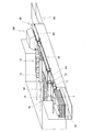
図1は液体噴射装置の概略斜視図、図2はその要部概略断面図である。これらの図面に示すように、液体噴射装置は、液体噴射ヘッドユニット10と、液体噴射ヘッドユニット10に相対向して下方に設けられたプラテン部20と、プラテン部20の側方に設けられたキャップ部30と、プラテン部20の上流側で印刷に供する記録媒体1を供給する媒体供給部40と、プラテン部20の下流側で印刷された記録媒体1を収容する媒体受容部50と、媒体供給部40から記録媒体1をプラテン部20上に搬送して印刷後の記録媒体1を媒体受容部50まで搬送する搬送手段60とを具備する。
Hereinafter, an example of the liquid ejecting apparatus of the invention will be described in detail.
FIG. 1 is a schematic perspective view of a liquid ejecting apparatus, and FIG. As shown in these drawings, the liquid ejecting apparatus is provided on the side of the liquid ejecting
液体噴射ヘッドユニット10は、複数の液体噴射ヘッド11を被噴射媒体としての記録媒体1の搬送方向に交差する方向に並設してライン印刷可能なものであり、移動バー12に載置されて搬送方向に交差する方向に移動自在であり、非動作時にはプラテン部20からキャップ部30へ移動可能となっている。
The liquid ejecting
ここで、液体噴射ヘッド11の構造及び噴射される液体の種類は特に限定されないが、本実施形態では、積層ピエゾ型の液体噴射ヘッド11とし、水系顔料インクを紙からなる記録媒体1に噴射するものとした。
Here, the structure of the
プラテン部20は、プラテン部20での記録媒体1の搬送ベルトを兼ねるプラテンベルト21を具備し、図2に示すように、プラテンベルト21は、上流側の駆動ロール22と、下流側の従動ロール23と、これらの間の下方に配置されるテンションロール24とに掛け渡された状態で回動可能に設けられている。ここで、プラテンベルト21は本発明の支持部に相当する。なお、プラテン部20の上流側及び下流側には、プラテンベルト21と同様な構成の搬送ベルト61及び62が設けられており、これらにより、記録媒体1を搬送する搬送手段60を構成している。
The
また、キャップ部30は、各液体噴射ヘッド11に対応して複数のキャップを具備するものであり、非動作時に液体噴射ヘッド11のノズル開口の面をキャップでキャッピングすることにより、液体噴射ヘッド11のノズル開口の乾燥を防止するものである。
The
そして、プラテン部20の上流側に配置された搬送ベルト61に対向する位置には、搬送ベルト61上を搬送される記録媒体1をプレ加熱する加熱手段70が設けられている。この加熱手段70は、搬送される記録媒体1の表面に接触して記録媒体1の表面を加熱するヒートロール71を具備し、ヒートロール71と記録媒体1との接触を十分にするために、ヒートロール71と対向して記録媒体1及び搬送ベルト61を挟持する対向ロール72が設けられている。
A
ここで、加熱手段70は、当該加熱手段70により加熱されてプラテン部20に搬送された記録媒体1の温度が所定温度となるように加熱条件が設定されるものであり、この加熱条件は制御手段80により制御されている。制御手段80は、環境温度や使用される記録媒体1などの設定情報に基づいて加熱条件を設定すると共に、本実施形態では、液体噴射ヘッドユニット10に設けられて記録媒体1の表面温度を検出する温度センサ81からの情報を取得して当該温度情報に基づいてフィードバック制御することにより、加熱条件の微調整を行っている。
Here, the
また、プラテン部20には、プラテン部20に搬送された記録媒体1を補助的に加熱する補助加熱手段90が設けられている。補助加熱手段90は、記録媒体1と被噴射面とは反対側から支持する支持部であるプラテンベルト21の裏面に接触するように設けられた加熱ヒータ91〜93からなる。加熱ヒータ91〜93は、液体噴射ヘッドユニット10の液体噴射ヘッド11のノズル開口の直下には対向しないように、搬送方向に亘って分割して設けられており、加熱ヒータ91〜93の間隙が液体噴射ヘッド11に相対向するように配置されている。
Further, the
かかる補助加熱手段90の加熱ヒータ91〜93は、加熱手段70によりプレ加熱された記録媒体1から逃げた熱を補うために設けられたものであり、プレ加熱によるプラテン部20に搬送された記録媒体1の狙いの温度である所定温度と同等又は若干高い一定温度に保持されたものである。
The
また、プラテン部20の下流側には、液体が噴射された記録媒体1をポスト加熱するポスト加熱手段100が設けられている。ポスト加熱手段100は、搬送ベルト62の上方に相対向して設けられた非接触式で記録媒体1を加熱する加熱手段であり、例えば、赤外線ヒータなどである。
Further, on the downstream side of the
以下、本実施形態の液体噴射装置の記録媒体1の加熱方式について、さらに詳細に説明する。
Hereinafter, the heating method of the
上述したように、特に水系の液体を噴射して印刷する場合においてブリード等を有効に防止するには、液滴の着弾する際の記録媒体1の表面温度が重要であることがわかった。また、記録媒体1として紙種を変更すると、背面側からの加熱では加熱条件の制御が難しく、記録媒体1の表面温度が所望の範囲から外れてしまうことが多々あることがわかった。
As described above, it has been found that the surface temperature of the
そこで、本発明では、上述したように記録媒体1を表面側から予め加熱する加熱手段70を設け、記録媒体1の表面温度を直接的に制御し、記録媒体1の表面温度をより簡便に所望の範囲にするようにした。
Therefore, in the present invention, as described above, the heating means 70 for preheating the
加熱手段70は、プラテン部20に搬送された記録媒体1の表面温度が所定温度となるようにプレ加熱するものであり、プレ加熱した後の搬送による冷却の程度を考慮してヒートロール71の温度を設定する。
The heating means 70 preheats the surface temperature of the
本実施形態では、プラテン部20に搬送された記録媒体1の表面温度が40〜45℃の範囲になるようにプレ加熱条件を調整することとした。
In the present embodiment, the preheating conditions are adjusted so that the surface temperature of the
このような表面温度となると、水系顔料インクからなる液滴が着弾した際に液滴の適正な蒸発乾燥が生じ、ブリード(混色)等による印刷品質の低下を防止することができる。すなわち、記録媒体1の表面温度が40℃未満の場合には、液滴の所望の蒸発乾燥が得られないためブリード(混色)等による印刷品質の低下を招くことがあり、好ましくない。一方、記録媒体1の表面温度が45℃より高いと、液体噴射ヘッド11のノズル開口の液体が乾燥して安定した吐出が得られなくなり、好ましくない。また、温度が高すぎると、液体噴射ヘッド11の接着部などの耐久寿命の低下に影響を与えたり、あるいはまた、液滴着弾後のドット径の広がりが必要以上に抑制されてしまうために却って多くの液滴量が必要となって好ましくない。
When such a surface temperature is reached, when the droplets made of water-based pigment ink land, the droplets are appropriately evaporated and dried, and deterioration of print quality due to bleeding (color mixing) or the like can be prevented. That is, when the surface temperature of the
また、本実施形態では、加熱手段70として、ヒートロール71を用い、記録媒体1の記録面に直接接触して加熱するようにしたが、これによれば、記録媒体1の表面を確実且つ効率的に所望の温度に加熱することができるという利点がある。勿論、非接触式の加熱方式を用いてもよく、何れにしても記録媒体1の表面温度を所望の範囲の温度とするのが好ましい。
Further, in the present embodiment, the
また、加熱手段70は、上述したようにプラテン部20に搬送された記録媒体1の表面温度が40〜45℃となるようにプレ加熱するものであり、プラテン部20までの搬送過程での放熱を考慮して加熱条件を設定するものであり、環境温度や使用する記録媒体1の種類、また、記録媒体1が紙の場合には、その坪量などに応じて加熱条件を設定できるようになっている。すなわち、記録媒体1が坪量が大きく厚手の場合には、加熱され難いので、加熱温度を高く設定する必要があり、また、記録媒体1が坪量が小さく薄手の場合には、加熱されやすいので、加熱温度を低めに設定する必要がある。また、環境温度が低温で放熱し易い環境であれば、高めに設定し、環境温度が高く放熱し難い環境であれば、低めの加熱温度とすればよい。
Further, the heating means 70 preheats the
ここで、本実施形態において、ヒートロール71の設定温度の一例を記録媒体1の坪量との関係で以下に示す。なお、記録媒体1の搬送速度が8〜12(IPS:inch/sec)の場合とする。
Here, in the present embodiment, an example of the set temperature of the

一般的には、このように設定を変更することにより、プラテン部20の記録媒体1の表面温度が40〜45℃となるようにすればよいが、本実施形態では、加熱手段70を制御する制御手段80を設けている。この制御手段80は、上述したように、温度センサ81からの温度情報を取得してこの温度情報に基づいて加熱手段70を制御するものである。温度センサ81は、非接触で記録媒体1の表面温度を検出できるものであれば、特に限定されない。また、制御手段80は、記録媒体1の位置情報を取得しており、温度センサ81の下方に記録媒体1が存在する際の温度情報を取得するようにしている。そして、制御手段80は、記録媒体1の表面温度が所定の温度範囲か否かを判断し、所定の範囲より低い場合には加熱条件を高温方向に制御し、所定の範囲より高い場合には、加熱条件を低温方向に制御するようにする。
In general, the surface temperature of the
また、補助加熱手段90の加熱ヒータ91〜93は、基本的には加熱条件は一定であり、本実施形態では、記録媒体1の狙いの温度に設定されており、プラテン部20上の記録媒体1に補助的に熱を与えている。しかしながら、加熱手段70の加熱条件と温度センサ81の温度情報によって、制御手段80がオンオフのみを制御するようにしてもよい。
Further, the heating conditions of the
また、加熱ヒータ91〜93は、上述したように、液体噴射ヘッド11の直下には配置されないように設けられている。これは、液体噴射ヘッド11の直下を加熱するとヘッドノズル面への影響が大きくなるためである。
Further, as described above, the
なお、ポスト加熱手段100は、印刷後の記録媒体1を媒体受容部50に積層するためにある程度乾燥させるためのものであり、本発明の目的である混色等の防止にはほとんど影響しない。よって、ポスト加熱手段100は、特に設けなくてもよいことはいうまでもない。
The post heating means 100 is for drying to some extent in order to stack the
(他の実施形態)
以上、一実施形態に係る液体噴射装置について説明したが、上述した実施形態に限定されるものではない。例えば、加熱手段70を接触式のヒートロール71を用いたものとしたが、非接触式の加熱手段としてもよい。図3及び図4には、非接触式の加熱手段として、赤外線ヒータ71Aを設けた例を示す。なお、赤外線ヒータ71Aを設けた以外は上述した実施形態と同様であるので、他の構成部材には同一符号を付し、重複する説明は省略する。
(Other embodiments)
The liquid ejecting apparatus according to one embodiment has been described above, but the present invention is not limited to the above-described embodiment. For example, although the
また、補助加熱手段90は、背面加熱方式を例示したが、液体噴射ヘッド11への影響を与えない程度のものであれば、表面側から非接触で加熱する加熱手段、例えば、赤外線ヒータ、温風加熱、輻射熱加熱ヒータなどとしてもよい。
Further, although the
また、本発明は、上述したように、水系の液体を噴射する液体噴射装置に好適に適用できるものであるが、溶剤系液体を噴射する装置に適用することもできる。また、水系の液体として、水系顔料インクを用いたが、水系の染料インクも同様に用いることができることはいうまでもない。 Further, as described above, the present invention can be suitably applied to a liquid ejecting apparatus that ejects an aqueous liquid, but can also be applied to an apparatus that ejects a solvent-based liquid. Further, although water-based pigment ink is used as the water-based liquid, it goes without saying that water-based dye ink can also be used in the same manner.
さらに、上述した実施形態では、記録媒体を搬送し、記録ヘッド及び加熱手段が固定であったが、逆に記録媒体を固定とし、記録ヘッド及び加熱手段が移動するようにしてもよい。この場合、加熱手段は、記録ヘッドに先行して移動し、記録媒体の相対移動方向上流側をプレ加熱する構成となる。この際に補助加熱手段を設ける場合には、補助加熱手段は、記録ヘッドの移動と共に移動する被噴射領域の移動範囲全体に設けられてもよいし、記録ヘッドと共に移動するように設けてもよい。また、補助加熱手段を記録ヘッドと共に移動するように設けた場合には、記録ヘッドのノズル開口の直下には対向しないように設けるようにするのが好ましい。 Furthermore, in the above-described embodiment, the recording medium is transported and the recording head and the heating unit are fixed. However, the recording medium may be fixed and the recording head and the heating unit may be moved. In this case, the heating unit moves in advance of the recording head and preheats the upstream side in the relative movement direction of the recording medium. In this case, when the auxiliary heating means is provided, the auxiliary heating means may be provided in the entire movement range of the ejection area that moves with the movement of the recording head, or may be provided so as to move with the recording head. . Further, when the auxiliary heating means is provided so as to move together with the recording head, it is preferable that the auxiliary heating means is provided so as not to face directly below the nozzle opening of the recording head.
また、上述した実施形態では、ライン印刷可能な液体噴射装置を例示したが、ヘッドユニットを走査するシリアル印刷タイプでもよい。 In the above-described embodiment, the liquid ejecting apparatus capable of line printing is exemplified, but a serial printing type in which the head unit is scanned may be used.
また、上述した実施形態では、縦振動型のインクジェット式記録ヘッドを例示したが、これに限定されず、例えば、撓み振動型のインクジェット式記録ヘッドや発熱素子の発熱で発生するバブルによってノズル開口から液滴を吐出するインクジェット式記録ヘッドを用いてもよい。 In the above-described embodiment, the longitudinal vibration type ink jet recording head is exemplified, but the present invention is not limited to this. For example, the flexural vibration type ink jet recording head or a bubble generated by the heat generated by the heating element can be An ink jet recording head that discharges droplets may be used.
1 記録媒体、 10 液体噴射ヘッドユニット、 11 液体噴射ヘッド、 20 プラテン部、 60 搬送手段、 70 加熱手段、 71 ヒートロール、 80 制御手段、 81 温度センサ
DESCRIPTION OF
Claims (6)
前記被噴射領域より前記被噴射媒体の相対移動方向上流側に、被噴射媒体を表面側から加熱する加熱手段を設け、前記被噴射領域の被噴射媒体の温度が所定範囲の温度となるようにプレ加熱することを特徴とする液体噴射装置。 A liquid ejecting head in which nozzle openings for ejecting liquid are arranged side by side, and at least one of the liquid ejecting head and the ejected medium are transported, and the liquid ejecting head and the ejected medium are moved relative to each other. A liquid ejecting apparatus including a conveying unit that makes both face each other in an ejection region,
A heating means for heating the ejected medium from the surface side is provided upstream of the ejected area in the relative movement direction of the ejected medium so that the temperature of the ejected medium in the ejected area becomes a temperature within a predetermined range. A liquid ejecting apparatus characterized by preheating.
Priority Applications (1)
| Application Number | Priority Date | Filing Date | Title |
|---|---|---|---|
| JP2008087781A JP2009241277A (en) | 2008-03-28 | 2008-03-28 | Liquid ejection device |
Applications Claiming Priority (1)
| Application Number | Priority Date | Filing Date | Title |
|---|---|---|---|
| JP2008087781A JP2009241277A (en) | 2008-03-28 | 2008-03-28 | Liquid ejection device |
Publications (2)
| Publication Number | Publication Date |
|---|---|
| JP2009241277A true JP2009241277A (en) | 2009-10-22 |
| JP2009241277A5 JP2009241277A5 (en) | 2010-10-21 |
Family
ID=41303782
Family Applications (1)
| Application Number | Title | Priority Date | Filing Date |
|---|---|---|---|
| JP2008087781A Withdrawn JP2009241277A (en) | 2008-03-28 | 2008-03-28 | Liquid ejection device |
Country Status (1)
| Country | Link |
|---|---|
| JP (1) | JP2009241277A (en) |
Cited By (6)
| Publication number | Priority date | Publication date | Assignee | Title |
|---|---|---|---|---|
| WO2014037814A3 (en) * | 2012-09-07 | 2014-07-03 | Funai Electric Co., Ltd. | Systems and methods for printing on a substrate |
| JP2015150824A (en) * | 2014-02-18 | 2015-08-24 | セイコーエプソン株式会社 | Inkjet recording method |
| WO2017203991A1 (en) * | 2016-05-27 | 2017-11-30 | コニカミノルタ株式会社 | Ink jet recording apparatus |
| US9919520B2 (en) | 2014-02-18 | 2018-03-20 | Seiko Epson Corporation | Ink jet recording method |
| JP2019162773A (en) * | 2018-03-19 | 2019-09-26 | 株式会社リコー | Drying device and liquid discharge device |
| JP7347902B2 (en) | 2019-09-17 | 2023-09-20 | 大阪シーリング印刷株式会社 | Printing device and inkjet printing method |
Citations (5)
| Publication number | Priority date | Publication date | Assignee | Title |
|---|---|---|---|---|
| JPH11198362A (en) * | 1997-11-05 | 1999-07-27 | Xerox Corp | Printing equipment for printing image containing liquid carrier-containing colorant in recording medium |
| JP2003001807A (en) * | 2001-06-21 | 2003-01-08 | Canon Inc | Recording apparatus |
| JP2003145728A (en) * | 2001-11-12 | 2003-05-21 | Konica Corp | Ink jet printer |
| JP2004074415A (en) * | 2002-08-09 | 2004-03-11 | Hitachi Printing Solutions Ltd | Dryer of inkjet printer |
| WO2004094150A1 (en) * | 2003-04-18 | 2004-11-04 | Mimaki Engineering Co., Ltd. | Ink jet printer |
-
2008
- 2008-03-28 JP JP2008087781A patent/JP2009241277A/en not_active Withdrawn
Patent Citations (5)
| Publication number | Priority date | Publication date | Assignee | Title |
|---|---|---|---|---|
| JPH11198362A (en) * | 1997-11-05 | 1999-07-27 | Xerox Corp | Printing equipment for printing image containing liquid carrier-containing colorant in recording medium |
| JP2003001807A (en) * | 2001-06-21 | 2003-01-08 | Canon Inc | Recording apparatus |
| JP2003145728A (en) * | 2001-11-12 | 2003-05-21 | Konica Corp | Ink jet printer |
| JP2004074415A (en) * | 2002-08-09 | 2004-03-11 | Hitachi Printing Solutions Ltd | Dryer of inkjet printer |
| WO2004094150A1 (en) * | 2003-04-18 | 2004-11-04 | Mimaki Engineering Co., Ltd. | Ink jet printer |
Cited By (14)
| Publication number | Priority date | Publication date | Assignee | Title |
|---|---|---|---|---|
| CN104602918A (en) * | 2012-09-07 | 2015-05-06 | 船井电机株式会社 | Systems and methods for printing on substrate |
| WO2014037814A3 (en) * | 2012-09-07 | 2014-07-03 | Funai Electric Co., Ltd. | Systems and methods for printing on a substrate |
| US9919520B2 (en) | 2014-02-18 | 2018-03-20 | Seiko Epson Corporation | Ink jet recording method |
| JP2015150824A (en) * | 2014-02-18 | 2015-08-24 | セイコーエプソン株式会社 | Inkjet recording method |
| JPWO2017203991A1 (en) * | 2016-05-27 | 2019-03-22 | コニカミノルタ株式会社 | Ink jet recording device |
| CN109153258A (en) * | 2016-05-27 | 2019-01-04 | 柯尼卡美能达株式会社 | Ink-jet recording apparatus |
| WO2017203991A1 (en) * | 2016-05-27 | 2017-11-30 | コニカミノルタ株式会社 | Ink jet recording apparatus |
| US20190126638A1 (en) * | 2016-05-27 | 2019-05-02 | Konica Minoita Inc. | Ink jet recording apparatus |
| CN109153258B (en) * | 2016-05-27 | 2020-04-24 | 柯尼卡美能达株式会社 | Ink jet recording apparatus |
| US10661581B2 (en) | 2016-05-27 | 2020-05-26 | Konica Minolta, Inc. | Ink jet recording apparatus |
| JP7047756B2 (en) | 2016-05-27 | 2022-04-05 | コニカミノルタ株式会社 | Inkjet recording device |
| JP2019162773A (en) * | 2018-03-19 | 2019-09-26 | 株式会社リコー | Drying device and liquid discharge device |
| JP7040177B2 (en) | 2018-03-19 | 2022-03-23 | 株式会社リコー | Drying device and liquid discharge device |
| JP7347902B2 (en) | 2019-09-17 | 2023-09-20 | 大阪シーリング印刷株式会社 | Printing device and inkjet printing method |
Similar Documents
| Publication | Publication Date | Title |
|---|---|---|
| US8231196B2 (en) | Continuous feed duplex printer | |
| US7360887B2 (en) | Image forming apparatus and method | |
| JP4963683B2 (en) | Inkjet recording device | |
| US6132038A (en) | Liquid ink printer having a self regulating contact drier | |
| US8567936B2 (en) | LED roll to roll drum printer systems, structures and methods | |
| JP5862324B2 (en) | Liquid ejector | |
| US20100194816A1 (en) | Inkjet printer | |
| JP2009241277A (en) | Liquid ejection device | |
| WO2013137073A1 (en) | Inkjet printing device | |
| US7997677B2 (en) | Convertible printer | |
| KR20180075594A (en) | Inkjet printer and inkjet printing method using same | |
| US8322841B2 (en) | Inkjet printing apparatus | |
| JPH1086353A (en) | Ink jetrecorder | |
| JP2012143874A (en) | Inkjet recording apparatus | |
| JP4600998B2 (en) | Inkjet printer | |
| JP2010201714A (en) | Inkjet recorder and inkjet recording method | |
| JP5035036B2 (en) | Recording device | |
| US5980136A (en) | Drum platen type printing machine for printing on regular and card-stock substrates | |
| US6231176B1 (en) | Self-tensioning flexible heater assembly for drying image bearing substrates in an ink jet printer | |
| JP4606134B2 (en) | Multi-stage pre-printed substrate heating assembly and ink image generating apparatus including the same | |
| US8985721B2 (en) | Printing apparatus and aging method | |
| JPH0516370A (en) | Image recorder | |
| JPH05286128A (en) | Hot-melt type ink jet printer | |
| US20020089577A1 (en) | Ink jet printer having a printhead assembly for recording high quality graphic images and photo quality images | |
| JP2020082570A (en) | Recording medium heating device, and liquid ejection device |
Legal Events
| Date | Code | Title | Description |
|---|---|---|---|
| A521 | Written amendment |
Free format text: JAPANESE INTERMEDIATE CODE: A821 Effective date: 20100830 |
|
| RD04 | Notification of resignation of power of attorney |
Effective date: 20100830 Free format text: JAPANESE INTERMEDIATE CODE: A7424 |
|
| RD03 | Notification of appointment of power of attorney |
Free format text: JAPANESE INTERMEDIATE CODE: A7423 Effective date: 20100831 |
|
| A521 | Written amendment |
Free format text: JAPANESE INTERMEDIATE CODE: A523 Effective date: 20100907 |
|
| A621 | Written request for application examination |
Free format text: JAPANESE INTERMEDIATE CODE: A621 Effective date: 20100907 |
|
| A977 | Report on retrieval |
Effective date: 20120220 Free format text: JAPANESE INTERMEDIATE CODE: A971007 |
|
| A131 | Notification of reasons for refusal |
Free format text: JAPANESE INTERMEDIATE CODE: A131 Effective date: 20120228 |
|
| A761 | Written withdrawal of application |
Effective date: 20120316 Free format text: JAPANESE INTERMEDIATE CODE: A761 |