JP2009238242A - Printer - Google Patents
Printer Download PDFInfo
- Publication number
- JP2009238242A JP2009238242A JP2009146108A JP2009146108A JP2009238242A JP 2009238242 A JP2009238242 A JP 2009238242A JP 2009146108 A JP2009146108 A JP 2009146108A JP 2009146108 A JP2009146108 A JP 2009146108A JP 2009238242 A JP2009238242 A JP 2009238242A
- Authority
- JP
- Japan
- Prior art keywords
- printing
- information
- printing medium
- printing apparatus
- printed
- Prior art date
- Legal status (The legal status is an assumption and is not a legal conclusion. Google has not performed a legal analysis and makes no representation as to the accuracy of the status listed.)
- Withdrawn
Links
- 239000000463 material Substances 0.000 claims description 68
- 239000000758 substrate Substances 0.000 claims description 67
- 238000012545 processing Methods 0.000 claims description 47
- 238000003384 imaging method Methods 0.000 claims description 17
- 238000004519 manufacturing process Methods 0.000 claims description 17
- 238000011144 upstream manufacturing Methods 0.000 claims description 17
- 238000012937 correction Methods 0.000 claims description 11
- 238000007599 discharging Methods 0.000 claims description 10
- 230000035945 sensitivity Effects 0.000 claims description 9
- 238000006243 chemical reaction Methods 0.000 claims description 6
- 238000005520 cutting process Methods 0.000 claims description 4
- 239000000123 paper Substances 0.000 description 287
- 238000003860 storage Methods 0.000 description 129
- 239000000976 ink Substances 0.000 description 121
- 230000005540 biological transmission Effects 0.000 description 78
- 230000007246 mechanism Effects 0.000 description 45
- 230000032258 transport Effects 0.000 description 39
- 238000000034 method Methods 0.000 description 37
- 230000008569 process Effects 0.000 description 32
- 238000010586 diagram Methods 0.000 description 28
- 238000013500 data storage Methods 0.000 description 19
- 239000003990 capacitor Substances 0.000 description 12
- 239000002184 metal Substances 0.000 description 9
- 230000002093 peripheral effect Effects 0.000 description 9
- 238000000926 separation method Methods 0.000 description 9
- 230000006870 function Effects 0.000 description 8
- 230000003287 optical effect Effects 0.000 description 8
- 239000004033 plastic Substances 0.000 description 7
- 230000006866 deterioration Effects 0.000 description 6
- 239000000428 dust Substances 0.000 description 6
- 238000005530 etching Methods 0.000 description 6
- 238000009826 distribution Methods 0.000 description 5
- 238000004891 communication Methods 0.000 description 4
- 230000000694 effects Effects 0.000 description 4
- 230000015572 biosynthetic process Effects 0.000 description 3
- 239000003086 colorant Substances 0.000 description 3
- 239000010985 leather Substances 0.000 description 3
- 238000012986 modification Methods 0.000 description 3
- 230000004048 modification Effects 0.000 description 3
- 239000002985 plastic film Substances 0.000 description 3
- 229920006255 plastic film Polymers 0.000 description 3
- 238000007789 sealing Methods 0.000 description 3
- 239000004065 semiconductor Substances 0.000 description 3
- 235000010724 Wisteria floribunda Nutrition 0.000 description 2
- 230000006399 behavior Effects 0.000 description 2
- 238000012840 feeding operation Methods 0.000 description 2
- 230000008901 benefit Effects 0.000 description 1
- 230000006378 damage Effects 0.000 description 1
- 230000014759 maintenance of location Effects 0.000 description 1
- 230000000717 retained effect Effects 0.000 description 1
Images


Classifications
-
- B—PERFORMING OPERATIONS; TRANSPORTING
- B41—PRINTING; LINING MACHINES; TYPEWRITERS; STAMPS
- B41J—TYPEWRITERS; SELECTIVE PRINTING MECHANISMS, i.e. MECHANISMS PRINTING OTHERWISE THAN FROM A FORME; CORRECTION OF TYPOGRAPHICAL ERRORS
- B41J11/00—Devices or arrangements of selective printing mechanisms, e.g. ink-jet printers or thermal printers, for supporting or handling copy material in sheet or web form
- B41J11/009—Detecting type of paper, e.g. by automatic reading of a code that is printed on a paper package or on a paper roll or by sensing the grade of translucency of the paper
-
- B—PERFORMING OPERATIONS; TRANSPORTING
- B41—PRINTING; LINING MACHINES; TYPEWRITERS; STAMPS
- B41J—TYPEWRITERS; SELECTIVE PRINTING MECHANISMS, i.e. MECHANISMS PRINTING OTHERWISE THAN FROM A FORME; CORRECTION OF TYPOGRAPHICAL ERRORS
- B41J3/00—Typewriters or selective printing or marking mechanisms characterised by the purpose for which they are constructed
- B41J3/44—Typewriters or selective printing mechanisms having dual functions or combined with, or coupled to, apparatus performing other functions
Abstract
Description
本発明は、被印刷体、被印刷体に設けられる素子、印刷装置、及び、コンピュータシステムに関する。 The present invention relates to a printing medium, an element provided on the printing medium, a printing apparatus, and a computer system.
(1)被印刷体、すなわちロール紙等の印刷メディアに関する情報を、ロール紙ユニットなどの一部(例えばロール紙の芯部)に設けた記憶素子に保有させ、印刷装置にて読み込むことが行われている。ロール紙などの残量、紙の種類、厚さ、幅などに関する属性情報を、自動的に印刷制御に反映させることにより、高品質の印刷結果を簡単に実現することができる。 (1) Information relating to a printing medium, that is, a print medium such as roll paper, is stored in a storage element provided in a part of the roll paper unit (for example, the core of the roll paper) and read by a printing apparatus. It has been broken. By automatically reflecting the attribute information related to the remaining amount of roll paper, paper type, thickness, width, etc. in the print control, a high-quality print result can be easily realized.
しかしながら、特に、カット紙などの単票メディアの場合は、大量の枚数のものをまとめてユニットとして扱うわけではなく、互いに異なる属性のものを一枚一枚印刷することが多い。そこで、普通は、パーソナルコンピュータの画面などにおいて、印刷装置のドライバソフトを用いてユーザがいちいち設定している。これは非常に手間がかかる。 However, in particular, in the case of cut sheet media such as cut sheets, a large number of sheets are not handled as a unit in many cases, and those having different attributes are often printed one by one. Therefore, the user normally makes settings on the screen of a personal computer or the like using the driver software of the printing apparatus. This is very time consuming.
ところで、近年、平面状のアンテナコイルとコンデンサ、及び超小型ICチップなどから構成される、ごく小型かつ薄型のメモリ素子が多種開発されている。 By the way, in recent years, various kinds of very small and thin memory elements composed of a planar antenna coil, a capacitor, an ultra-small IC chip and the like have been developed.
これは、ICカードなどにおいて使用されているものであり、半導体メモリやコンピュータ回路が備えられて、素子自体が演算処理機能を有し、接触式/非接触式の読み書きセンサによりデータの送受信が行われる。バーコード等の印刷情報よりも保有できる情報量が格段に大きく、製造コストも安価になりつつある。 This is used in IC cards and the like, is equipped with a semiconductor memory and a computer circuit, the element itself has an arithmetic processing function, and data is transmitted / received by a contact / non-contact read / write sensor. Is called. The amount of information that can be held is much larger than the printing information such as barcodes, and the manufacturing cost is becoming cheaper.
そこで、このような小型のメモリ素子を利用して、印刷メディア自体にあらかじめ様々なメディア属性情報を記憶させておくことが考えられる。 Therefore, it is conceivable to store various media attribute information in advance in the print medium itself using such a small memory element.
また、他方で、上記のような印刷メディア自体の属性情報ではなく、印刷結果に関する情報も、のちのち重要となることがある。印刷結果に関する情報とは、例えば、印刷を実行した印刷装置がどのような印刷装置であったか、又は、印刷対象であったデータは、どのようなデータで、コンピュータのハードディスク内のどこに保存されていたものであったか、などである。これらの情報は、後日同じ画像、品質の印刷結果を得る必要があるときなどは、重要な情報である。ところが、単に記憶に頼るのみでは忘れてしまうことが多い。また、印刷装置のドライバソフトにこれらの情報を保存する機能があったとしても、異なる場所で前回とは異なるコンピュータで印刷する場合などは、利用することができない。 On the other hand, not only the attribute information of the print medium itself as described above but also information related to the print result may become important later. The information related to the printing result is, for example, what kind of printing apparatus the printing apparatus executed printing is, or what kind of data is the printing target and stored in the hard disk of the computer Was it a thing? These pieces of information are important information when it is necessary to obtain the same image and quality printing results at a later date. However, it is often forgotten by simply relying on memory. Even if the driver software of the printing apparatus has a function of storing these information, it cannot be used when printing on a computer different from the previous time in a different place.
(2)また、前述したように、被印刷体、すなわちロール紙等の印刷メディアに関する情報を、ロール紙ユニットなどの一部(例えばロール紙の芯部)に設けた記憶素子に保有させ、印刷装置にて読み込むことが行われている。ロール紙などの残量、紙の種類、厚さ、幅などに関する属性情報を、自動的に印刷制御に反映させることにより、高品質の印刷結果を簡単に実現することができる。 (2) In addition, as described above, information relating to the printing medium, that is, the printing medium such as roll paper, is held in a storage element provided in a part of the roll paper unit (for example, the core of the roll paper) and printed Reading is performed by the device. By automatically reflecting the attribute information related to the remaining amount of roll paper, paper type, thickness, width, etc. in the print control, a high-quality print result can be easily realized.
しかしながら、特に、カット紙などの単票メディアの場合は、互いに異なる属性のものを一枚一枚印刷することが多い。そこで、普通は、パーソナルコンピュータの画面などにおいて、印刷装置のドライバソフトを用いてユーザがいちいち設定している。これは非常に手間がかかる。 However, in particular, in the case of single-cut media such as cut sheets, it is often the case that sheets having different attributes are printed one by one. Therefore, the user normally makes settings on the screen of a personal computer or the like using the driver software of the printing apparatus. This is very time consuming.
そこで、単票メディアの場合にも、印刷装置に設けた光学センサにより、被印刷体の種類(普通紙、光沢紙、OHP用紙など)を読み取り、適切な印刷制御を実行することが行われている。また、メディア自体にあらかじめバーコードなどを印刷することにより、被印刷体自体に情報を保有させておくことも知られている。 Therefore, even in the case of cut sheet media, an optical sensor provided in the printing apparatus reads the type of printing medium (plain paper, glossy paper, OHP paper, etc.) and executes appropriate printing control. Yes. In addition, it is also known that information is retained in the printing medium itself by printing a barcode or the like in advance on the medium itself.
しかしながら、光学センサ等により、メディアの反射光等から読み取ることのできる情報は、紙の光沢や透過性(OHP用紙の場合など)等の非常に限られたものである。また、バーコードなどの印刷された情報に保有させることのできる情報量は非常に小さく、ごく限られた印刷制御に利用することしかできない。また、光学センサなどによる読み取り処理は、ばらつきが大きく、不正確な属性情報を得てしまうことも多い。 However, information that can be read from the reflected light of the medium by an optical sensor or the like is very limited such as the gloss and transparency of the paper (such as in the case of OHP paper). Further, the amount of information that can be held in printed information such as a barcode is very small and can only be used for limited printing control. In addition, reading processing by an optical sensor or the like has large variations and often obtains inaccurate attribute information.
ところで、近年、平面状のアンテナコイルとコンデンサ、及び超小型ICチップなどから構成される、ごく小型かつ薄型のメモリ素子が多種開発されている。 By the way, in recent years, various kinds of very small and thin memory elements composed of a planar antenna coil, a capacitor, an ultra-small IC chip and the like have been developed.
これは、ICカードなどにおいて使用されているものであり、半導体メモリやコンピュータ回路が備えられて、素子自体が演算処理機能を有し、接触式/非接触式の読み書きセンサによりデータの送受信が行われる。バーコード等の印刷情報よりも保有できる情報量が格段に大きく、製造コストも安価になりつつある。 This is used in IC cards and the like, is equipped with a semiconductor memory and a computer circuit, the element itself has an arithmetic processing function, and data is transmitted / received by a contact / non-contact read / write sensor. Is called. The amount of information that can be held is much larger than the printing information such as barcodes, and the manufacturing cost is becoming cheaper.
(3)さらにまた、デジタルカメラ、デジタルビデオ、デジタルカメラ付き携帯電話等の種々の撮影装置によって撮影を行い、該撮影によって得られた画像データに基づいてインクジェットプリンタ、レーザビームプリンタ等の各種印刷装置によって紙等の被印刷体に印刷が行われる。 (3) Still further, various printing apparatuses such as a digital camera, a digital video, a digital camera, a mobile phone with a digital camera, and the like, and various printing apparatuses such as an ink jet printer and a laser beam printer based on the image data obtained by the photographing. Thus, printing is performed on a printing medium such as paper.
撮影によって得られた画像データは、パーソナルコンピュータに取り込まれて適宜修正や編集がなされた後に、印刷装置に送られて印刷が行われる場合もあるし、パーソナルコンピュータを介することなく、撮影装置から直接、又は、記録メディアを介して印刷装置に送られて印刷が行われる場合もある。 Image data obtained by shooting may be sent to a printing apparatus after being taken into a personal computer and appropriately corrected or edited, and may be printed, or directly from the shooting apparatus without going through a personal computer. Alternatively, printing may be performed by being sent to a printing apparatus via a recording medium.
また、近年、平面状のアンテナコイルとコンデンサ、及び超小型ICチップなどから構成される、ごく小型かつ薄型のメモリ素子が多種開発されている。これは、ICカードなどにおいて使用されているものであり、半導体メモリやコンピュータ回路が備えられて、素子自体が演算処理機能を有し、接触式/非接触式の読み書きセンサによりデータの送受信が行われる。バーコード等の印刷情報よりも保有できる情報量が格段に大きく、製造コストも安価になりつつある。 In recent years, various types of extremely small and thin memory elements composed of a planar antenna coil, a capacitor, an ultra-small IC chip, and the like have been developed. This is used in IC cards and the like, is equipped with a semiconductor memory and a computer circuit, the element itself has an arithmetic processing function, and data is transmitted / received by a contact / non-contact read / write sensor. Is called. The amount of information that can be held is much larger than the printing information such as barcodes, and the manufacturing cost is becoming cheaper.
撮影装置によって生成された画像データに基づいて印刷が行われた被印刷体を後日見た際に、撮影を行った際の撮影条件を知りたい場合がある。例えば、富士山をデジタルカメラで撮影し、インクジェットプリンタで紙に印刷をした場合、富士山の印刷された紙を後日見た際に、何年何月何日に、どのような機種のデジタルカメラを用いて、どの程度のシャッター速度にて撮影したか等の撮影条件を知りたいことがある。 There are cases where it is desired to know the photographing conditions when photographing is performed when a printed material on which printing has been performed based on image data generated by the photographing device is viewed at a later date. For example, if Mt. Fuji is photographed with a digital camera and printed on paper with an inkjet printer, when you view Mt. Fuji's printed paper at a later date, what kind of digital camera will be used Sometimes, it is desirable to know the shooting conditions such as the shutter speed at which the image was taken.
このような観点から、被印刷体の印刷面に印刷を行う際に、画像とともに、撮影年月日等の撮影条件をも印刷してしまうことが行われている。 From such a viewpoint, when printing is performed on the printing surface of the printing medium, printing conditions such as the shooting date are also printed together with the image.
しかしながら、画像に重ねて撮影条件を印刷してしまうことは好ましくない。 However, it is not preferable to print the shooting conditions over the image.
また、画像と重なることなく撮影条件を印刷する場合には、撮影条件を印刷するための領域を画像印刷領域とは別に被印刷体に確保する必要が生じてしまう。 Further, when printing the shooting conditions without overlapping the image, it is necessary to secure an area for printing the shooting conditions on the printing medium separately from the image printing area.
そこで、本発明はかかる課題(上記(1)〜(3)に記載の課題)に鑑みてなされたもので、被印刷体に関する様々な情報を被印刷体自身に保有させることのできる被印刷体、かかる被印刷体に設けられる素子、かかる被印刷体に対して印刷を行う印刷装置、及び、かかる印刷装置及び印刷装置と接続されるコンピュータ本体を有するコンピュータシステムを実現することを目的とする。 Accordingly, the present invention has been made in view of such problems (the problems described in (1) to (3) above), and the printing medium that can hold various information related to the printing medium itself. It is an object of the present invention to realize a computer system including an element provided on such a printing medium, a printing apparatus that performs printing on the printing medium, and a computer main body connected to the printing apparatus and the printing apparatus.
また、本発明は、撮影条件や出力制御情報等を好適に被印刷体自身に保有させることのできる被印刷体、かかる被印刷体に設けられる素子、かかる被印刷体に対して印刷を行う印刷装置、及び、コンピュータシステムを実現することにある。 In addition, the present invention provides a printing medium in which the printing medium itself can preferably hold shooting conditions, output control information, and the like, an element provided on the printing medium, and printing for performing printing on the printing medium. It is to implement an apparatus and a computer system.
前記課題を解決するために、主たる本発明は、印刷装置による情報の書き込みが可能な素子を有していることを特徴とする被印刷体であることを特徴とする。 In order to solve the above-mentioned problems, the main present invention is a printed material having an element in which information can be written by a printing apparatus.
また、前記課題を解決するために、他の主たる本発明は、情報を書き込み可能な素子を有し、撮影装置よって生成された画像データに基づいて印刷装置によって印刷が行われる被印刷体において、前記素子に、前記撮影装置による前記画像データの生成が行われた際の撮影条件が、前記印刷装置によって書き込まれることを特徴とする。 In order to solve the above-mentioned problem, another main present invention is an object to be printed on which has an element capable of writing information and is printed by a printing device based on image data generated by a photographing device. A photographing condition when the image data is generated by the photographing device is written into the element by the printing device.
また、前記課題を解決するために、他の主たる本発明は、情報を書き込み可能な素子を有し、印刷装置によって印刷が行われる被印刷体において、前記素子には、印刷装置における画像データの出力状態を制御する出力制御情報が、前記印刷装置によって書き込まれることを特徴とする。 In order to solve the above-described problem, another main present invention includes an element in which information can be written, and in a printing medium on which printing is performed by a printing apparatus, the element includes image data in the printing apparatus. Output control information for controlling an output state is written by the printing apparatus.
本発明の他の特徴については、添付図面及び本明細書の記載により明らかにする。 Other features of the present invention will become apparent from the accompanying drawings and the description of this specification.
以下の開示により、少なくとも次のことが明らかにされる。 The following disclosure will reveal at least the following.
印刷装置による情報の書き込みが可能な素子を有していることを特徴とする被印刷体。 A printed material having an element on which information can be written by a printing apparatus.
かかる被印刷体によれば、忘れられたり失われたりしやすい、印刷結果に関連する様々な属性情報を、被印刷体に設けられた書き込み可能素子に書き込んで保存しておくことができるので、後日同じデータを印刷する際に重要となるそれらの属性情報を容易に利用することができる。 According to such a printing medium, various attribute information related to the printing result, which is easily forgotten or lost, can be written and stored in a writable element provided on the printing medium. The attribute information that is important when printing the same data at a later date can be easily used.
また、前記素子には、前記被印刷体に印刷を行った印刷装置を特定するための情報が書き込まれることとしてもよい。 The element may be written with information for specifying a printing apparatus that has performed printing on the substrate.
印刷時の色変換情報など一部の印刷情報は印刷装置種類毎に異なるので、前回使用した印刷装置種類を忘れてしまうと同じ印刷結果を再現することに困難を生ずる。そこで、かかる被印刷体によれば、被印刷体に設けられた書き込み可能素子に、印刷を行った印刷装置を特定する情報を書き込んで保存しておくことができるので、後日同じデータを印刷する際に、前回と同じ印刷装置を容易に特定することができ、その属性情報を容易に利用することができる。 Since some print information such as color conversion information at the time of printing differs for each type of printing apparatus, it becomes difficult to reproduce the same printing result if the type of printing apparatus used last time is forgotten. Therefore, according to such a printing medium, information specifying the printing apparatus that performed printing can be written and stored in a writable element provided on the printing medium, so that the same data is printed at a later date. In this case, it is possible to easily specify the same printing apparatus as the previous time, and to easily use the attribute information.
また、前記素子には、前記被印刷体に対する印刷の対象となった画像データを記録する際に使用されたデジタルカメラを特定するための情報が書き込まれることとしてもよい。 The element may be written with information for specifying a digital camera used when recording image data to be printed on the substrate.
色補正などの画像処理に関する情報はデジタルカメラ毎に異なるので、画像データを記録したデジタルカメラ種類を忘れてしまうと同じ画像処理結果、ひいては印刷結果を再現することに困難を生ずる。そこで、かかる被印刷体によれば、被印刷体に設けられた書き込み可能素子に、画像データを記録したデジタルカメラを特定する情報を書き込んで保存しておくことができるので、後日同じ画像データを画像処理し、印刷する際に、前回と同じデジタルカメラを容易に特定することができ、その属性情報を容易に利用することができる。 Since information related to image processing such as color correction differs for each digital camera, forgetting the type of the digital camera that recorded the image data causes difficulty in reproducing the same image processing result and consequently the printing result. Therefore, according to such a printing medium, information that identifies the digital camera that recorded the image data can be written and stored in a writable element provided on the printing medium. When image processing and printing are performed, the same digital camera as the previous one can be easily specified, and the attribute information can be easily used.
また、前記素子には、前記被印刷体に印刷を行った日付を特定するための情報が書き込まれることとしてもよい。 The element may be written with information for specifying a date on which printing is performed on the substrate.
かかる被印刷体によれば、例えば、印刷された画像の時間経過に対する劣化具合を知りたいような場合に、素子に書き込まれた印刷日付情報を読み取ることによって、簡単に印刷日付を調べることができる。 According to such a printing medium, for example, when it is desired to know the degree of deterioration of a printed image over time, the printing date can be easily checked by reading the printing date information written on the element.
また、前記素子には、前記被印刷体に対する印刷の対象となった画像データを特定するための情報が書き込まれることとしてもよい。 The element may be written with information for specifying image data to be printed on the substrate.
かかる被印刷体によれば、印刷対象の画像データを特定するための情報(画像ファイルのファイル名や、コンピュータハードディスクにおけるファイルのパス名など)を、被印刷体に設けられた書き込み可能素子に書き込んで保存しておくことができるので、後日その被印刷体に印刷されている画像の画像データを記憶に頼ることなく容易に特定できる。 According to such a printing medium, information for specifying image data to be printed (file name of an image file, path name of a file in a computer hard disk, etc.) is written in a writable element provided on the printing medium. Therefore, it is possible to easily specify the image data of the image printed on the printing material at a later date without depending on the storage.
また、前記素子には、前記被印刷体に対する印刷の対象となった画像データが書き込まれることとしてもよい。 The element may be written with image data to be printed on the substrate.
同じ画像を後日再度印刷したいような場合には、無論、もとの画像が保存されているコンピュータなどから再度印刷装置に出力すればよい。ところが、そのコンピュータが近くにない移動先などにおいて、急に追加印刷が必要になった場合は、印刷できない。印刷結果である被印刷体を携帯していれば、コピー機やスキャナを用いて、印刷画像のイメージ読み取りを行い、複製することはできるが、コピー機やスキャナによる読み取り印刷を繰り返すと画像は次第に劣化する。そこで、かかる被印刷体によれば、当該被印刷体に印刷された画像データそのものを被印刷体の記憶素子に書き込んで保存しておくことができるので、その画像データを何らかの読取手段を用いて読み取った上で印刷すれば、画像劣化のない印刷結果を簡単に得ることができる。 If you want to print the same image again at a later date, of course, you can output it to the printing device again from the computer where the original image is stored. However, printing cannot be performed if additional printing is suddenly needed at a destination where the computer is not nearby. If you have a printed material that is the result of printing, you can use a copier or scanner to scan the image of the printed image and duplicate it, but if you repeat scanning and printing with the copier or scanner, the image will gradually to degrade. Therefore, according to such a printing medium, the image data itself printed on the printing medium can be written and stored in the storage element of the printing medium, so that the image data can be read using some reading means. If printing is performed after reading, a print result without image deterioration can be easily obtained.
また、前記素子には、前記被印刷体に対する印刷の対象となった画像データが記憶され、記憶された画像データは、画像データ読み取り手段を備えた印刷装置によって印刷装置に読み込まれることとしてもよい。 The element may store image data to be printed on the substrate, and the stored image data may be read into the printing apparatus by a printing apparatus having an image data reading unit. .
かかる被印刷体によれば、当該被印刷体に印刷された画像データそのものが保存された記憶素子の画像データを読み取り、印刷することによって、画像劣化のない印刷結果を簡単に得ることができる。 According to such a printing medium, it is possible to easily obtain a printing result without image deterioration by reading and printing the image data of the storage element storing the image data itself printed on the printing medium.
また、前記被印刷体の厚さが、0.5mm以上であることとしてもよい。 Further, the thickness of the substrate to be printed may be 0.5 mm or more.
このように、例えば厚紙などのように一定以上の厚さを有する被印刷体とすれば、前記素子を埋め込むことが容易である。また、耐変形性を有する柔軟な構造でなく硬質な構造の記憶素子であっても、印刷装置の給紙構造を直線的なものとすれば、印刷実行時の素子の変形、破壊を防止することができる。 In this manner, for example, if the printed material has a certain thickness or more, such as cardboard, the element can be easily embedded. Even if the memory element is not a flexible structure having deformation resistance but a hard structure, if the paper feeding structure of the printing apparatus is made linear, the element is prevented from being deformed or broken during printing. be able to.
また、前記被印刷体は、前記印刷装置によって切断されることなく印刷が行われることとしてもよい。 Further, the printing material may be printed without being cut by the printing apparatus.
前記印刷装置によって切断されることなく印刷が行われる被印刷体である場合には、特に効果的に上述した効果が奏される。 The effect described above is particularly effective when the printing medium is printed without being cut by the printing apparatus.
また、前記被印刷体の厚さが、0.5mm以上であり、前記被印刷体に関する情報を記憶するための素子が設けられており、前記素子には、前記被印刷体に印刷を行った印刷装置を特定するための情報、前記被印刷体に対する印刷の対象となった画像データを記録する際に使用されたデジタルカメラを特定するための情報、前記被印刷体に印刷を行った日付を特定するための情報、及び、前記被印刷体に対する印刷の対象となった画像データが書き込まれ、書き込まれた画像データは、画像データ読み取り手段を備えた印刷装置によって印刷装置に読み込まれることとしてもよい。 In addition, the thickness of the substrate to be printed is 0.5 mm or more, and an element for storing information on the substrate to be printed is provided. The element was printed on the substrate to be printed. Information for specifying a printing device, information for specifying a digital camera used for recording image data to be printed on the substrate, and date of printing on the substrate Information for specifying and image data to be printed on the substrate to be printed may be written, and the written image data may be read into the printing apparatus by a printing apparatus having image data reading means. Good.
このようにすれば、前記素子を埋め込むことが容易であり、かつ、硬質な構造の記憶素子であっても、変形、破壊されることなく印刷することができる被印刷体であって、色変換情報などの印刷装置毎に異なる印刷属性情報や、色補正などのデジタルカメラ毎に異なる画像処理情報、及び印刷日付情報を容易に利用しつつ、当該被印刷体に印刷された画像データそのものが保存された記憶素子の画像データを読み取り、印刷することができるので、スキャナ読み取りなどによる画像劣化もなく、前回の印刷結果と同じ品質の印刷結果を簡単に得ることができる。 In this way, the element can be easily embedded, and even a memory element having a hard structure can be printed without being deformed or destroyed. The image data itself printed on the substrate can be saved while easily using different print attribute information such as information, image processing information different for each digital camera such as color correction, and print date information. Since the image data stored in the storage element can be read and printed, it is possible to easily obtain a print result having the same quality as the previous print result without image deterioration due to scanner reading or the like.
被印刷体に関する情報を記憶するための素子が設けられていることを特徴とする被印刷体。 An element for storing information relating to a printing medium is provided.
かかる被印刷体によれば、光学センサなどを用いて被印刷体自体から読み取ることのできる情報よりも、詳細かつ正確な被印刷体に関する情報を保有させておくことができるので、その情報を取得することにより印刷装置の印字ヘッド制御などをより詳細かつ正確に行うことができる。また、記憶素子を被印刷体そのものに設けたので、ユーザがいちいちパーソナルコンピュータのプリンタ設定画面などから被印刷体に関する詳細な情報を入力する必要が無く、簡単に印刷制御を行うことができる。 According to such a printing medium, information about the printing medium can be held in detail and more accurately than information that can be read from the printing medium itself using an optical sensor or the like. By doing so, the print head control of the printing apparatus and the like can be performed in more detail and accurately. Further, since the memory element is provided on the printing medium itself, it is not necessary for the user to input detailed information about the printing medium from the printer setting screen of the personal computer, and printing control can be easily performed.
また、前記被印刷体の、前記印刷装置に挿入される際に先頭となる部分に、前記素子が設けられているようにしてもよい。 In addition, the element may be provided in a portion of the substrate to be printed when it is inserted into the printing apparatus.
かかる被印刷体によれば、前記被印刷体の記憶素子に書き込まれた情報を早い時点で読み取ることができ、被印刷体の給紙動作において、逆方向に戻す動作を行う必要が無い。 According to such a printing medium, information written in the storage element of the printing medium can be read at an early time, and there is no need to perform an operation of returning to the reverse direction in the paper feeding operation of the printing medium.
また、前記被印刷体の厚さが、0.5mm以上であるようにしてもよい。 The thickness of the printing medium may be 0.5 mm or more.
このように、例えば厚紙などのように一定以上の厚さを有する被印刷体とすれば、前記素子を埋め込むことが容易である。また、耐変形性を有する柔軟な構造でなく硬質な構造の記憶素子であっても、印刷装置の給紙構造を直線的なものとすれば、印刷実行時の素子の変形、破壊を防止することができる。 In this manner, for example, if the printed material has a certain thickness or more, such as cardboard, the element can be easily embedded. Even if the memory element is not a flexible structure having deformation resistance but a hard structure, if the paper feeding structure of the printing apparatus is made linear, the element is prevented from being deformed or broken during printing. be able to.
また、前記素子には、前記被印刷体の種類を特定するための情報、前記被印刷体の厚さを特定するための情報、前記被印刷体の幅を特定するための情報、前記被印刷体の製造年月日を特定するための情報、又は、前記被印刷体に応じた色変換を行う際に参照される情報などが記憶されていることとしてもよい。 The element includes information for specifying the type of the printing medium, information for specifying the thickness of the printing medium, information for specifying the width of the printing medium, and the printing Information for specifying the date of manufacture of the body or information referred to when performing color conversion according to the printing medium may be stored.
かかる被印刷体によれば、光学センサなどで読み取る場合よりも詳細かつ正確なこれらの情報を、素子に保有させておくことにより、より詳細かつ正確な印刷制御を行うことができ、高品質の印刷結果を実現することができる。 According to such a printing medium, it is possible to perform more detailed and accurate printing control by holding these elements with detailed and accurate information than in the case of reading with an optical sensor or the like. A printing result can be realized.
また、前記素子に記憶された情報は、前記印刷装置に設けられた読み込み手段によって該印刷装置に読み込まれることとしてもよい。 Further, the information stored in the element may be read into the printing apparatus by reading means provided in the printing apparatus.
かかる被印刷体によれば、従来はパーソナルコンピュータ画面上などにおいて、いちいちユーザが詳細な印刷設定を行っていたものを、印刷装置が直接、被印刷体より印刷情報を読み取って印刷制御に反映させるので、正確かつ詳細な印刷制御を簡単に行うことができ、高品質の印刷結果を得ることができる。 According to such a printing medium, the printing apparatus directly reads the printing information from the printing medium and reflects it in the printing control, which is conventionally performed by the user on the personal computer screen or the like. Therefore, accurate and detailed printing control can be easily performed, and high-quality printing results can be obtained.
また、前記読み取り手段は、非接触式の読み取り手段であることとしてもよい。 The reading unit may be a non-contact type reading unit.
かかる被印刷体によれば、前記素子と読み取り手段とを接触させる必要が無いので、構成が容易となる。 According to such a printing medium, it is not necessary to bring the element into contact with the reading means, so that the configuration becomes easy.
また、前記被印刷体は、前記印刷装置によって切断されることなく印刷が行われることとしてもよい。 Further, the printing material may be printed without being cut by the printing apparatus.
前記印刷装置によって切断されることなく印刷が行われる被印刷体である場合には、特に効果的に上述した効果が奏される。 The effect described above is particularly effective when the printing medium is printed without being cut by the printing apparatus.
また、前記印刷装置は、前記被印刷体に印刷を行うための移動可能な印刷ヘッドと、この印刷ヘッドの移動方向と交差する方向に前記被印刷体を搬送して位置決めするための搬送位置決め手段を有し、前記素子に記憶された情報は、前記搬送位置決め手段による前記被印刷体の搬送方向において、該搬送位置決め手段よりも上流側に設けられた読み取り手段によって該印刷装置に読み込まれることとしてもよい。 In addition, the printing apparatus includes a movable print head for printing on the printing medium, and a conveyance positioning unit for conveying and positioning the printing medium in a direction that intersects the moving direction of the printing head. The information stored in the element is read into the printing apparatus by a reading unit provided upstream of the conveyance positioning unit in the conveyance direction of the printing medium by the conveyance positioning unit. Also good.
かかる被印刷体によれば、記憶素子に記憶された情報を印刷装置において早い時期に読み込むことができるので、印刷制御の設定を正確に行うことができる。 According to such a printing medium, the information stored in the storage element can be read in the printing apparatus at an early stage, so that the print control can be set accurately.
また、前記印刷装置は、前記被印刷体に印刷を行うための移動可能な印刷ヘッドを有し、前記素子に記憶された情報は、該印刷ヘッドとともに移動する読み取り手段によって該印刷装置に読み込まれることとしてもよい。 The printing apparatus has a movable print head for printing on the printing medium, and information stored in the element is read into the printing apparatus by reading means that moves together with the print head. It is good as well.
かかる被印刷体によれば、被印刷体の形状や寸法が様々に変化しても、臨機応変に記憶素子の情報を読み込むことができ、高度な印刷制御を行うことができる。 According to such a printing medium, even if the shape and dimensions of the printing medium are variously changed, information in the storage element can be read in a flexible manner, and advanced printing control can be performed.
また、前記素子は、前記被印刷体の、前記印刷装置に挿入される際に先頭となる部分に設けられており、前記被印刷体の厚さが、0.5mm以上であり、前記素子には、前記被印刷体の種類を特定するための情報、前記被印刷体の厚さを特定するための情報、前記被印刷体の幅を特定するための情報、前記被印刷体の製造年月日を特定するための情報、及び、前記被印刷体に応じた色変換を行う際に参照される情報が記憶されており、前記素子に記憶された情報は、前記印刷装置に設けられた非接触式の読み取り手段によって該印刷装置に読み込まれることとしてもよい。 Further, the element is provided at a leading portion of the printed body when inserted into the printing apparatus, and the thickness of the printed body is 0.5 mm or more, Is information for specifying the type of the printing body, information for specifying the thickness of the printing body, information for specifying the width of the printing body, and the date of manufacture of the printing body Information for specifying the day and information to be referred to when performing color conversion according to the substrate to be printed are stored, and the information stored in the element is stored in the non-printing device. It may be read into the printing apparatus by contact-type reading means.
かかる被印刷体によれば、前記被印刷体の記憶素子に書き込まれた情報を早い時点で読み取ることができ、被印刷体の給紙動作において、逆方向に戻す動作を行う必要が無い。また、厚紙などのように一定以上の厚さを有する被印刷体なので、前記素子を埋め込むことが容易であり、耐変形性を有する柔軟な構造でなく硬質な構造の記憶素子であっても、印刷装置の給紙構造を直線的なものとすれば、印刷実行時の素子の変形、破壊を防止することができる。また、光学センサなどで読み取る場合よりも詳細かつ正確な情報を、素子に保有させておくことにより、より詳細かつ正確な印刷制御を行うことができ、高品質の印刷結果を実現することができる。また、構成の容易な非接触式の読み取り手段により読み込まれることにより、ユーザの手入力に代って印刷装置が直接、被印刷体より印刷情報を読み取って印刷制御に反映させるので、正確かつ詳細な印刷制御を簡単に行うことができ、高品質の印刷結果を得ることができる。 According to such a printing medium, information written in the storage element of the printing medium can be read at an early time, and there is no need to perform an operation of returning to the reverse direction in the paper feeding operation of the printing medium. In addition, since the printed material has a certain thickness or more, such as cardboard, it is easy to embed the element, and even a memory element having a hard structure instead of a flexible structure having deformation resistance, If the paper feeding structure of the printing apparatus is linear, it is possible to prevent deformation and destruction of the element during printing. In addition, by keeping detailed and accurate information in the element than when reading with an optical sensor or the like, more detailed and accurate printing control can be performed, and high-quality printing results can be realized. . In addition, since the printing apparatus reads the printing information directly from the printing medium and reflects it in the printing control instead of the manual input by the user by being read by the non-contact type reading means with easy configuration, it is accurate and detailed. Printing control can be easily performed, and high-quality printing results can be obtained.
情報を書き込み可能な素子を有し、撮影装置よって生成された画像データに基づいて印刷装置によって印刷が行われる被印刷体において、前記素子に、前記撮影装置による前記画像データの生成が行われた際の撮影条件が、前記印刷装置によって書き込まれることを特徴とする被印刷体。 In an object to be printed that has an element to which information can be written and is printed by a printing apparatus based on image data generated by an imaging apparatus, the image data is generated by the imaging apparatus on the element. The printing medium is characterized in that shooting conditions at the time are written by the printing apparatus.
かかる被印刷体によれば、前記撮影装置による前記画像データの生成が行われた際の撮影条件を、被印刷体に設けられた書き込み可能な素子に書き込んで保存しておくことができるので、被印刷体に撮影条件を印刷しなくとも、後日撮影条件を容易に知ることができる。 According to such a printing medium, the photographing conditions when the image data is generated by the photographing apparatus can be written and stored in a writable element provided in the printing body. Even if the shooting conditions are not printed on the printing medium, the shooting conditions can be easily known at a later date.
また、前記撮影装置は、デジタルカメラであることとしてもよい。 Further, the photographing apparatus may be a digital camera.
かかる被印刷体によれば、デジタルカメラによる前記画像データの生成が行われた際の撮影条件を、被印刷体に設けられた書き込み可能な素子に書き込んで保存しておくことができるので、被印刷体に撮影条件を印刷しなくとも、後日デジタルカメラにて撮影した際の撮影条件を容易に知ることができる。 According to such a printing medium, the photographing conditions when the image data is generated by the digital camera can be written and stored in a writable element provided on the printing medium. Even if the shooting conditions are not printed on the printed material, it is possible to easily know the shooting conditions when shooting with a digital camera at a later date.
また、前記撮影装置による前記画像データの生成が行われた年月日を特定するための情報が、前記素子に、前記撮影条件として前記印刷装置によって書き込まれることとしてもよい。 In addition, information for specifying the date on which the image data is generated by the imaging apparatus may be written to the element by the printing apparatus as the imaging condition.
かかる被印刷体によれば、前記撮影装置による前記画像データの生成が行われた際の年月日を、被印刷体に設けられた書き込み可能な素子に書き込んで保存しておくことができるので、被印刷体に撮影年月日を印刷しなくとも、後日撮影年月日を容易に知ることができる。 According to such a printing medium, the date when the image data is generated by the photographing apparatus can be written and stored in a writable element provided on the printing medium. Even if the shooting date is not printed on the printing medium, it is possible to easily know the shooting date at a later date.
また、前記撮影装置としてのデジタルカメラの機種を特定するための情報が、前記素子に、前記撮影条件として前記印刷装置によって書き込まれることとしてもよい。 In addition, information for specifying the model of the digital camera as the photographing apparatus may be written in the element by the printing apparatus as the photographing condition.
かかる被印刷体によれば、前記撮影装置としてのデジタルカメラの機種を、被印刷体に設けられた書き込み可能な素子に書き込んで保存しておくことができるので、被印刷体に撮影年月日を印刷しなくとも、後日デジタルカメラの機種を容易に知ることができる。 According to such a printing medium, since the model of the digital camera as the photographing apparatus can be written and stored in a writable element provided on the printing medium, the shooting date is recorded on the printing medium. Even without printing, you can easily know the model of the digital camera at a later date.
また、前記撮影装置としてのデジタルカメラの撮影時におけるシャッター速度を特定するための情報が、前記素子に、前記撮影条件として前記印刷装置によって書き込まれることとしてもよい。 In addition, information for specifying a shutter speed at the time of photographing by the digital camera as the photographing device may be written in the element by the printing device as the photographing condition.
かかる被印刷体によれば、前記撮影装置としてのデジタルカメラの撮影時におけるシャッター速度を、被印刷体に設けられた書き込み可能な素子に書き込んで保存しておくことができるので、被印刷体にシャッター速度を印刷しなくとも、後日シャッター速度を容易に知ることができる。 According to such a printing medium, the shutter speed at the time of photographing by the digital camera as the photographing apparatus can be written and stored in a writable element provided on the printing medium. Even without printing the shutter speed, the shutter speed can be easily known at a later date.
また、前記撮影装置としてのデジタルカメラの撮影時の絞り値を特定するための情報が、前記素子に、前記撮影条件として前記印刷装置によって書き込まれることとしてもよい。 In addition, information for specifying an aperture value at the time of photographing by the digital camera as the photographing device may be written to the element by the printing device as the photographing condition.
かかる被印刷体によれば、前記撮影装置としてのデジタルカメラの撮影時の絞り値を、被印刷体に設けられた書き込み可能な素子に書き込んで保存しておくことができるので、被印刷体に絞り値を印刷しなくとも、後日絞り値を容易に知ることができる。 According to such a printing medium, the aperture value at the time of photographing by the digital camera as the photographing apparatus can be written and stored in a writable element provided on the printing medium. Even if the aperture value is not printed, the aperture value can be easily known at a later date.
また、前記撮影装置としてのデジタルカメラのISO感度相当値を特定するための情報が、前記素子に、前記撮影条件として前記印刷装置によって書き込まれることとしてもよい。 Further, information for specifying an ISO sensitivity equivalent value of a digital camera as the photographing apparatus may be written into the element by the printing apparatus as the photographing condition.
かかる被印刷体によれば、前記撮影装置としてのデジタルカメラのISO感度相当値を、被印刷体に設けられた書き込み可能な素子に書き込んで保存しておくことができるので、被印刷体にISO感度相当値を印刷しなくとも、後日ISO感度相当値を容易に知ることができる。 According to such a printing medium, the ISO sensitivity equivalent value of the digital camera as the photographing apparatus can be written and stored in a writable element provided on the printing medium, so that the ISO is stored on the printing medium. Even if the sensitivity equivalent value is not printed, the ISO sensitivity equivalent value can be easily known at a later date.
また、前記撮影装置としてのデジタルカメラによる撮影時にフラッシュを使用したか否かを特定するための情報が、前記素子に、前記撮影条件として前記印刷装置によって書き込まれることとしてもよい。 In addition, information for specifying whether or not a flash is used at the time of photographing with a digital camera as the photographing apparatus may be written into the element by the printing apparatus as the photographing condition.
かかる被印刷体によれば、前記撮影装置としてのデジタルカメラによる撮影時にフラッシュを使用したか否かを、被印刷体に設けられた書き込み可能な素子に書き込んで保存しておくことができるので、被印刷体にフラッシュ情報を印刷しなくとも、後日フラッシュ情報を容易に知ることができる。 According to such a printing medium, whether or not the flash was used at the time of shooting by the digital camera as the shooting device can be written and stored in a writable element provided on the printing medium. Even if the flash information is not printed on the printing medium, the flash information can be easily known at a later date.
また、前記素子には、前記被印刷体に対する印刷の対象となった画像データが書き込まれることとしてもよい。 The element may be written with image data to be printed on the substrate.
同じ画像を後日再度印刷したいような場合には、無論、もとの画像が保存されているコンピュータなどから再度印刷装置に出力すればよい。ところが、そのコンピュータが近くにない移動先などにおいて、急に追加印刷が必要になった場合は、印刷できない。印刷結果である被印刷体を携帯していれば、コピー機やスキャナを用いて、印刷画像のイメージ読み取りを行い、複製することはできるが、コピー機やスキャナによる読み取り印刷を繰り返すと画像は次第に劣化する。そこで、かかる被印刷体によれば、当該被印刷体に印刷された画像データそのものを被印刷体の素子に書き込んで保存しておくことができるので、その画像データを何らかの読取手段を用いて読み取った上で印刷すれば、画像劣化のない印刷結果を簡単に得ることができる。 If you want to print the same image again at a later date, of course, you can output it to the printing device again from the computer where the original image is stored. However, printing cannot be performed if additional printing is suddenly needed at a destination where the computer is not nearby. If you have a printed material that is the result of printing, you can use a copier or scanner to scan the image of the printed image and duplicate it, but if you repeat scanning and printing with the copier or scanner, the image will gradually to degrade. Therefore, according to such a printing medium, the image data itself printed on the printing medium can be written and stored in the elements of the printing medium, so that the image data is read using some reading means. In addition, if printing is performed, a print result without image deterioration can be easily obtained.
また、前記素子に、前記撮影装置による前記画像データの生成が行われた際の撮影条件が、前記印刷装置によって非接触状態にて書き込まれることしてもよい。 In addition, a photographing condition when the image data is generated by the photographing device may be written in the element in a non-contact state by the printing device.
また、前記被印刷体の厚さが、0.5mm以上であることとしてもよい。 Further, the thickness of the substrate to be printed may be 0.5 mm or more.
このように、例えば厚紙などのように一定以上の厚さを有する被印刷体とすれば、前記素子を埋め込むことが容易である。また、耐変形性を有する柔軟な構造でなく硬質な構造の記憶素子であっても、印刷装置の給紙構造を直線的なものとすれば、印刷実行時の素子の変形、破壊を防止することができる。 In this manner, for example, if the printed material has a certain thickness or more, such as cardboard, the element can be easily embedded. Even if the memory element is not a flexible structure having deformation resistance but a hard structure, if the paper feeding structure of the printing apparatus is made linear, the element is prevented from being deformed or broken during printing. be able to.
また、前記被印刷体は、前記印刷装置によって切断されることなく印刷が行われることとしてもよい。 Further, the printing material may be printed without being cut by the printing apparatus.
前記印刷装置によって切断されることなく印刷が行われる被印刷体である場合には、特に効果的に上述した効果が奏される。 The effect described above is particularly effective when the printing medium is printed without being cut by the printing apparatus.
また、被印刷体の全表面を対象として、前記撮影装置よって生成された画像データに基づいて、前記印刷装置によって印刷が行われることしてもよい。 Further, printing may be performed by the printing apparatus based on image data generated by the photographing apparatus with respect to the entire surface of the printing medium.
被印刷体の全表面を対象として印刷が行われる場合には、撮影条件を被印刷体に印刷してしまうと、撮影条件と画像とが重なって印刷されてしまうという不都合が生じ得る。しかしながら、前記撮影装置による前記画像データの生成が行われた際の撮影条件を、被印刷体に設けられた書き込み可能な素子に書き込んで保存しておくことによって、かかる不都合の発生を防止することができる。 When printing is performed on the entire surface of the printing medium, if the shooting conditions are printed on the printing medium, the shooting conditions and the image may overlap and be printed. However, it is possible to prevent the occurrence of such inconvenience by writing and storing the photographing conditions when the image data is generated by the photographing apparatus in a writable element provided on the printing medium. Can do.
また、情報を書き込み可能な素子を有し、デジタルカメラよって生成された画像データに基づいて印刷装置によって印刷が行われる被印刷体において、前記素子には、前記デジタルカメラによる前記画像データの生成が行われた年月日を特定するための情報、及び、前記画像データが、前記印刷装置によって非接触状態にて書き込まれ、厚さが、0.5mm以上であり、前記印刷装置によって切断されることなく、その全表面を対象として、前記撮影装置よって生成された画像データに基づいて、前記印刷装置によって印刷が行われることを特徴とする被印刷体も実現可能である。 In addition, in a printing medium having an element in which information can be written and printing is performed by a printing apparatus based on image data generated by a digital camera, the image data is generated by the digital camera in the element. The information for specifying the date and time when it was performed and the image data are written in a non-contact state by the printing apparatus, and the thickness is 0.5 mm or more, and is cut by the printing apparatus. Without any problem, it is also possible to realize a printing medium in which printing is performed by the printing device based on the image data generated by the photographing device with respect to the entire surface.
また、情報を書き込み可能な素子を有し、印刷装置によって印刷が行われる被印刷体において、前記素子には、印刷装置における画像データの出力状態を制御する出力制御情報が、前記印刷装置によって書き込まれることを特徴とする被印刷体。 Further, in a printing medium having an element in which information can be written and printing is performed by a printing apparatus, output control information for controlling an output state of image data in the printing apparatus is written to the element by the printing apparatus. A printed material characterized by being printed.
また、前記印刷装置は、画像データを格納した画像ファイルから前記出力制御情報を読み取り、読み取った該出力制御情報を、前記素子に書き込むこととしてもよい。 The printing apparatus may read the output control information from an image file storing image data, and write the read output control information to the element.
また、前記出力制御情報は、ガンマ値、色空間、コントラスト、カラーバランス、シャープネス、色補正、および強調色を指定して、前記印刷装置における画像処理を制御するデータであることとしてもよい。 The output control information may be data for controlling image processing in the printing apparatus by designating a gamma value, color space, contrast, color balance, sharpness, color correction, and emphasized color.
また、前記出力制御情報は、印刷メディア、解像度、印刷ヘッドの動作方向を指定して、前記印刷装置における画像出力処理を制御するデータであることとしてもよい。 The output control information may be data for controlling an image output process in the printing apparatus by designating a print medium, a resolution, and an operation direction of the print head.
また、前記画像ファイルは、デジタルカメラにおいて生成された画像ファイルであることとしてもよい。 The image file may be an image file generated in a digital camera.
また、被印刷体に設けられた素子であって、前記素子は、前記印刷装置による情報の書き込みが可能であることを特徴とする素子も実現可能である。 In addition, an element provided on a print medium, which is characterized in that information can be written by the printing apparatus, can be realized.
また、被印刷体に設けられる素子であって、前記被印刷体に関する情報が記憶されることを特徴とする素子も実現可能である。 Further, it is possible to realize an element provided on the printing medium, in which information about the printing medium is stored.
また、被印刷体に設けられる素子であって、被印刷体に設けられた後に、撮影装置による画像データの生成が行われた際の撮影条件が、印刷装置によって書き込まれることを特徴とする素子も実現可能である。 An element provided on a printing medium, the imaging condition being written by the printing apparatus when the image data is generated by the imaging apparatus after being provided on the printing body. Is also feasible.
また、被印刷体に対して印刷を行う印刷装置において、前記被印刷体に設けられた素子に対して情報を書き込むための書き込み手段を有していることを特徴とする印刷装置も実現可能である。 In addition, a printing apparatus that performs printing on a printing medium can also be realized by including a writing unit that writes information to an element provided on the printing medium. is there.
また、かかる印刷装置において、被印刷体に対してインクを吐出するインク吐出ヘッドを有し、前記書き込み手段は、前記被印刷体の搬送方向において、該インク吐出ヘッドよりも上流側に設けられていることしてもよい。 The printing apparatus may further include an ink ejection head that ejects ink onto the printing medium, and the writing unit may be provided upstream of the ink ejection head in the conveyance direction of the printing medium. You may be.
前記書き込み手段を、前記被印刷体の搬送方向において、該インク吐出ヘッドよりも上流側に設けることにより、該インク吐出ヘッドによるインク吐出が行われて印刷が実行される前に、素子に対して情報を書き込むことが可能となる。 By providing the writing means on the upstream side of the ink discharge head in the transport direction of the printing medium, before the ink is discharged by the ink discharge head and printing is performed on the element, It becomes possible to write information.
また、かかる印刷装置において、前記被印刷体が印刷装置に対して所定の位置に位置した際に、前記書き込み手段による前記素子に対する情報の書き込みが行われ、該位置において、該素子に記憶された情報の読み込みも可能であることとしてもよい。 In such a printing apparatus, when the substrate to be printed is positioned at a predetermined position with respect to the printing apparatus, information is written to the element by the writing unit, and the information is stored in the element at the position. Information may be read.
かかる印刷装置によれば、前記被印刷体が印刷装置に対して所定の位置に位置した状態で、前記素子に対する情報の書き込み、及び、読み込みがともに可能となる。 According to such a printing apparatus, information can be written to and read from the element in a state where the printing medium is located at a predetermined position with respect to the printing apparatus.
また、かかる印刷装置において、水平状態でセットされた被印刷体を、該水平状態を維持しつつ搬送する搬送手段を有していることとしてもよい。 In addition, the printing apparatus may include a transport unit that transports the printing medium set in a horizontal state while maintaining the horizontal state.
かかる印刷装置によれば、被印刷体の剛性が高い場合等であっても、該被印刷体に設けられた素子に対して効果的に情報を書き込むことが可能となる。 According to such a printing apparatus, even when the printing medium has a high rigidity, information can be effectively written into the elements provided on the printing medium.
また、被印刷体に対して印刷を行う印刷装置において、前記被印刷体に設けられた素子に対して画像データを書き込むための書き込み手段と、素子に書き込まれた画像データを読み取るための読み取り手段を有していることを特徴とする印刷装置も実現可能である。 In addition, in a printing apparatus that performs printing on a printing medium, writing means for writing image data to an element provided on the printing medium, and reading means for reading image data written on the element It is also possible to realize a printing apparatus characterized by having
また、被印刷体に対して印刷を行う印刷装置において、前記被印刷体に設けられた素子に記憶された、該被印刷体に関する情報を読み込むための読み込み手段を有することを特徴とする印刷装置も実現可能である。 Further, in the printing apparatus for printing on the printing medium, the printing apparatus includes reading means for reading information on the printing medium stored in an element provided on the printing medium. Is also feasible.
また、前記被印刷体に印刷を行うための移動可能な印刷ヘッドと、この印刷ヘッドの移動方向と交差する方向に前記被印刷体を搬送して位置決めするための搬送位置決め手段を有し、前記読み取り手段は、前記搬送位置決め手段による前記被印刷体の搬送方向において、該搬送位置決め手段よりも上流側に設けられていることを特徴とする印刷装置も実現可能である。 A movable print head for performing printing on the printing medium; and a conveyance positioning unit for conveying and positioning the printing medium in a direction intersecting a moving direction of the printing head, It is also possible to realize a printing apparatus in which the reading unit is provided on the upstream side of the conveyance positioning unit in the conveyance direction of the printing medium by the conveyance positioning unit.
また、前記被印刷体に印刷を行うための移動可能な印刷ヘッドを有し、前記読み取り手段は、該印刷ヘッドとともに移動することを特徴とする印刷装置も実現可能である。 In addition, it is possible to realize a printing apparatus that includes a movable print head for printing on the printing medium, and the reading unit moves together with the print head.
また、前記読み取り手段は、非接触式の読み取り手段であることを特徴とする印刷装置も実現可能である。 Further, it is possible to realize a printing apparatus in which the reading unit is a non-contact type reading unit.
また、かかる印刷装置において、水平状態でセットされた被印刷体を、該水平状態を維持しつつ搬送する搬送手段を有していることとしてもよい。 In addition, the printing apparatus may include a transport unit that transports the printing medium set in a horizontal state while maintaining the horizontal state.
かかる印刷装置によれば、被印刷体の剛性が高い場合等であっても、該被印刷体に設けられ素子に記憶された情報を効果的に読み込むことが可能となる。 According to such a printing apparatus, even when the rigidity of the printing medium is high, it is possible to effectively read the information provided in the printing medium and stored in the element.
また、撮影装置よって生成された画像データに基づいて被印刷体に対して印刷を行う印刷装置において、前記被印刷体に設けられた素子に、前記撮影装置による前記画像データの生成が行われた際の撮影条件を書き込むことを特徴とする印刷装置も実現可能である。 Further, in the printing apparatus that performs printing on the printing medium based on the image data generated by the photographing apparatus, the image data is generated by the photographing apparatus on an element provided on the printing medium. It is also possible to realize a printing apparatus characterized by writing the shooting conditions at the time.
また、かかる印刷装置において、前記撮影装置は、デジタルカメラであることとしてもよい。 In the printing apparatus, the photographing apparatus may be a digital camera.
また、かかる印刷装置において、前記撮影装置による前記画像データの生成が行われた年月日を特定するための情報を、前記素子に、前記撮影条件として書き込むこととしてもよい。 In this printing apparatus, information for specifying the date on which the image data is generated by the imaging apparatus may be written as the imaging condition in the element.
また、かかる印刷装置において、前記撮影装置としてのデジタルカメラの機種を特定するための情報を、前記素子に、前記撮影条件として書き込むこととしてもよい。 In this printing apparatus, information for specifying the model of the digital camera as the photographing apparatus may be written in the element as the photographing condition.
また、かかる印刷装置において、前記撮影装置としてのデジタルカメラの撮影時におけるシャッター速度を特定するための情報を、前記素子に、前記撮影条件として書き込むこととしてもよい。 In this printing apparatus, information for specifying a shutter speed at the time of shooting by the digital camera as the shooting apparatus may be written as the shooting condition in the element.
また、かかる印刷装置において、前記撮影装置としてのデジタルカメラの撮影時の絞り値を特定するための情報を、前記素子に、前記撮影条件として書き込むこととしてもよい。 In this printing apparatus, information for specifying an aperture value at the time of shooting by the digital camera as the shooting apparatus may be written as the shooting condition in the element.
また、かかる印刷装置において、前記撮影装置としてのデジタルカメラのISO感度相当値を特定するための情報を、前記素子に、前記撮影条件として書き込むこととしてもよい。 In the printing apparatus, information for specifying an ISO sensitivity equivalent value of the digital camera as the photographing apparatus may be written in the element as the photographing condition.
また、かかる印刷装置において、前記撮影装置としてのデジタルカメラによる撮影時にフラッシュを使用したか否かを特定するための情報を、前記素子に、前記撮影条件として書き込むこととしてもよい。 Further, in such a printing apparatus, information for specifying whether or not a flash has been used at the time of photographing by a digital camera as the photographing apparatus may be written in the element as the photographing condition.
また、かかる印刷装置において、前記素子に、前記被印刷体に対する印刷の対象となった画像データを書き込むこととしてもよい。 In the printing apparatus, image data that is a target of printing on the substrate may be written in the element.
また、かかる印刷装置において、前記素子に、前記撮影装置による前記画像データの生成が行われた際の撮影条件を非接触状態にて書き込むこととしてもよい。 In the printing apparatus, the imaging condition when the image data is generated by the imaging apparatus may be written in the element in a non-contact state.
また、かかる印刷装置において、前記被印刷体を切断することなく印刷を行うこととしてもよい。 Moreover, in such a printing apparatus, it is good also as performing printing, without cut | disconnecting the said to-be-printed body.
また、かかる印刷装置において、前記被印刷体の全表面を対象として、前記撮影装置よって生成された画像データに基づいて印刷を行うこととしてもよい。 In the printing apparatus, printing may be performed on the entire surface of the printing object based on image data generated by the photographing apparatus.
また、かかる印刷装置において、被印刷体に対してインクを吐出するインク吐出ヘッドを有し、前記素子に前記撮影条件を書き込むための書き込み手段が、被印刷体の搬送方向において、該インク吐出ヘッドよりも上流側に設けられていることとしてもよい。 Further, in this printing apparatus, the ink discharge head that discharges ink to the printing medium, and a writing unit for writing the photographing condition to the element is arranged in the conveyance direction of the printing medium. It is good also as providing in the upstream rather than.
前記書き込み手段を、前記被印刷体の搬送方向において、該インク吐出ヘッドよりも上流側に設けることにより、該インク吐出ヘッドによるインク吐出が行われて印刷が実行される前に、素子に対して情報を書き込むことが可能となる。 By providing the writing means on the upstream side of the ink discharge head in the transport direction of the printing medium, before the ink is discharged by the ink discharge head and printing is performed on the element, It becomes possible to write information.
また、かかる印刷装置において、水平状態でセットされた被印刷体を、該水平状態を維持しつつ搬送する搬送手段を有していることとしてもよい。 In addition, the printing apparatus may include a transport unit that transports the printing medium set in a horizontal state while maintaining the horizontal state.
かかる印刷装置によれば、被印刷体の剛性が高い場合等であっても、該被印刷体に設けられた素子に対して効果的に情報を書き込むことが可能となる。 According to such a printing apparatus, even when the printing medium has a high rigidity, information can be effectively written into the elements provided on the printing medium.
また、画像データに基づいて被印刷体に印刷を行う印刷装置において、前記被印刷体に設けられた素子に、印刷装置における画像データの出力状態を制御する出力制御情報を書き込むことを特徴とする印刷装置。 In the printing apparatus that prints on the printing medium based on the image data, output control information for controlling the output state of the image data in the printing apparatus is written in an element provided on the printing medium. Printing device.
また、画像データを格納した画像ファイルから前記出力制御情報を読み取り、読み取った該出力制御情報を、前記素子に書き込むこととしてもよい。 The output control information may be read from an image file storing image data, and the read output control information may be written to the element.
また、前記出力制御情報は、ガンマ値、色空間、コントラスト、カラーバランス、シャープネス、色補正、および強調色を指定して、前記印刷装置における画像処理を制御するデータであることとしてもよい。 The output control information may be data for controlling image processing in the printing apparatus by designating a gamma value, color space, contrast, color balance, sharpness, color correction, and emphasized color.
また、前記出力制御情報は、印刷メディア、解像度、印刷ヘッドの動作方向を指定して、前記印刷装置における画像出力処理を制御するデータであることとしてもよい。 The output control information may be data for controlling an image output process in the printing apparatus by designating a print medium, a resolution, and an operation direction of the print head.
また、前記画像ファイルは、デジタルカメラにおいて生成された画像ファイルであることとしてもよい。 The image file may be an image file generated in a digital camera.
また、コンピュータ本体、このコンピュータ本体と接続されて被印刷体に対して印刷を行う印刷装置を有するコンピュータシステムにおいて、前記印刷装置は、前記被印刷体に設けられた素子に対して情報を書き込むための書き込み手段を有していることを特徴とするコンピュータシステムも実現可能である。 Further, in a computer system having a computer main body and a printing apparatus connected to the computer main body and performing printing on the printing medium, the printing apparatus writes information to an element provided on the printing medium. It is also possible to realize a computer system characterized by having the writing means.
また、コンピュータ本体、このコンピュータ本体と接続されて被印刷体に対して印刷を行う印刷装置を有するコンピュータシステムにおいて、前記印刷装置は、前記被印刷体に設けられた素子に記憶された、該被印刷体に関する情報を読み込むための読み込み手段を有することを特徴とするコンピュータシステムも実現可能である。 Further, in a computer system having a computer main body and a printing apparatus connected to the computer main body for printing on the printing medium, the printing apparatus is stored in an element provided on the printing medium. It is also possible to realize a computer system characterized by having reading means for reading information relating to a printed material.
また、コンピュータ本体、及び、このコンピュータ本体と接続されて撮影装置よって生成された画像データに基づいて被印刷体に対して印刷を行う印刷装置を有するコンピュータシステムにおいて、前記印刷装置が、前記被印刷体に設けられた素子に、前記撮影装置による前記画像データの生成が行われた際の撮影条件を書き込むことを特徴とするコンピュータシステムも実現可能である。 Further, in a computer system having a computer main body and a printing device that is connected to the computer main body and prints on a printing medium based on image data generated by a photographing apparatus, the printing apparatus includes the printing target. It is also possible to realize a computer system in which a photographing condition when the image data is generated by the photographing device is written in an element provided on the body.
=第1実施形態=
===インクジェットプリンタの概略===
次に、本発明の主な適用対象である印刷装置としてのインクジェットプリンタの概略について説明する。図1は、インクジェットプリンタの概略的な外観を示した図である。
= First embodiment =
=== Outline of Inkjet Printer ===
Next, an outline of an ink jet printer as a printing apparatus to which the present invention is applied will be described. FIG. 1 is a diagram showing a schematic appearance of an inkjet printer.
ここでは、カラーインクジェットプリンタを示した。このカラープリンタ1010は、カラー画像の出力が可能なインクジェットプリンタであり、例えば、シアン(C)、マゼンタ(M)、イエロ(Y)、ブラック(K)の4色の色インクをカット紙などの被印刷体上に吐出してドットを形成することによって画像を形成するインクジェット方式のプリンタである。なお、色インクとして、上記4色に加えて、ライトシアン(薄いシアン、LC)、ライトマゼンタ(薄いマゼンタ、LM)、ダークイエロ(暗いイエロ、DY)を用いても良い。
Here, a color inkjet printer is shown. The
図1に示すように、カラープリンタ1010は、背面側上方から供給されたカット紙を前面から排出する給紙構造を備えている。プリンタ本体1010の前面には操作パネル1011、排紙部1012が備えられ、背面には給紙部1013が備えられている。操作パネル1011には、各種操作ボタン1111、表示ランプ1112が設けられている。排紙部1012は、不使用時に排紙口を塞ぐ排紙トレー1121が備えられている。
As shown in FIG. 1, the
給紙部1013には、図示していないカット紙を保持する給紙トレー1131が備えられている。なお、カット紙とは、予め所定の寸法に切断された紙であり、カラープリンタ1010によって切断されることのない単票の印刷メディアである。
The
===給紙機構の構成===
本実施形態のカラープリンタ1010は、特に、ストレートパスと呼ばれるもう1つの給紙経路(図1には示していない)を有する構成のものである。これは、厚紙などの一定の厚さや硬さを有する被印刷体を手差しにより供給する給紙機構である。このストレートパス機構では、CD−Rなどの変則的な寸法、形状の被印刷体に対しても、被印刷体搬送トレー(図示していない)に載置して供給することにより、被印刷体を切断することなく印刷を行うことが可能である。図2は、これら2つの給紙機構について説明するための、プリンタ1010の要部断面図である。
=== Configuration of Paper Feed Mechanism ===
The
カラープリンタ1010には、被印刷体に印刷を行う手段として、摺動軸1044に軸支され、摺動軸方向(主走査方向)に移動するキャリッジ1040が設けられており、このキャリッジ1040には、被印刷体にインクを吐出して印刷を行うヘッドIH1〜IH4が搭載されている。ヘッドIH1〜IH4と対向して、ヘッドIH1〜IH4のヘッド面と被印刷体とのギャップを規定するプラテン1042が設けられている。そして、キャリッジ1040を主走査方向に搬送し、被印刷体をキャリッジ1040とプラテン1042との間で副走査方向Yに間欠的に搬送しながら、ヘッドIH1〜IH4が被印刷体にインクを吐出することによって、被印刷体に印刷が行われる。
The
給紙トレー1131は、例えば普通紙やフォト紙等のカット紙である被印刷体を供給することが可能な構成であり、被印刷体を自動供給するためのASF(オート・シート・フィーダー)が設けられている。ASFは、給紙トレー1131に設けられた給紙ローラ1132、及び図示していない分離パッドを有する自動給紙機構である。給紙ローラ1132は、略D形の横断面形状を有しており、ステッピング・モータ等の回転駆動力により回転制御される。そして、給紙ローラ1132の回転駆動力と分離パッドの摩擦抵抗によって、複数の被印刷体が一度に給紙されることを防ぐ。
The
そして、矢印Aで示した経路に沿ってASFにより自動給紙された被印刷体は、給紙ローラ1132より副走査方向Yの下流側に配設された被印刷体搬送位置決め手段により、印刷実行領域に向けて、所定の紙送り量で間欠的に搬送される。
Then, the printing medium automatically fed by the ASF along the path indicated by the arrow A is printed by the printing medium conveyance positioning unit arranged on the downstream side in the sub-scanning direction Y from the
被印刷体を副走査方向Yに間欠的に搬送し、位置決めする搬送位置決め手段として、搬送駆動ローラ1061と搬送従動ローラ1062が設けられている。搬送駆動ローラ1061は、ステッピング・モータ等の紙送りモータにより回転制御され、被印刷体は搬送駆動ローラ1061の回転により副走査方向Yに搬送される。搬送従動ローラ1062は、複数の搬送従動ローラホルダ1621に軸支されている。被印刷体が搬送駆動ローラ1061の回転により搬送される際に、搬送従動ローラ1062は、従動して回転する。
A
また、給紙ローラ1132と搬送駆動ローラ1061との間には、従来技術において公知の技術による紙検出器1063が配設されている。紙検出器1063は、立位姿勢への自己復帰習性が付与され、かつ記録紙搬送方向にのみ回動し得るよう被印刷体の搬送経路内に突出する状態で枢支されたレバー1631を有する。このレバー1631の先端が被印刷体に押されることにより、レバー1631が回動し、それによって被印刷体が検出される構成である。紙検出器1063は、給紙ローラ1132より給紙された被印刷体の始端位置、及び終端位置を検出し、その検出位置に合わせて印刷領域が決定され、印刷が実行される。
Further, a
一方、印刷された被印刷体を排紙する手段として、排紙駆動ローラ1064と排紙従動ローラ1065が設けられている。排紙駆動ローラ1064は、ステッピング・モータ等の回転駆動力により回転制御され、排紙駆動ローラ1064の回転により、被記録材は副走査方向Yに排紙される。排紙従動ローラ1065は、周囲に複数の歯を有し、各歯の先端が被印刷体の記録面に点接触するように鋭角的に尖っている歯付きローラであり、それぞれ、被印刷体が排紙駆動ローラ1064の回転により排紙される際に従動して回転する。
On the other hand, a
さらに、プリンタ1010には、上述したASFによる給紙経路(符号Aの矢印で示した経路)とは別に、記憶素子を埋設させた厚紙など、柔軟性の少ない被印刷体などを供給するための給紙路が設けられている。図中、この給紙路を符号Bの矢印で示している。そして、プリンタ1010は、この矢印Bの給紙路から給紙された被印刷体に対しても、前記ASFから給紙された被印刷体と同様に印刷を実行することができる。
Further, in addition to the above-described ASF paper feed path (the path indicated by the arrow A), the
さらに、プリンタ1010は、図示していないが、搬送従動ローラレリース機構を備えている。被印刷体をセット位置にセットする際に、搬送従動ローラ1062を搬送駆動ローラ1061から離間させた状態(レリース状態)に保持し、被印刷体を給紙路に挿入して印刷セット位置にセットし、印刷セット位置への位置合わせ完了後に、そのレリース状態を解除し、搬送従動ローラ1062が搬送駆動ローラ1061によって付勢される状態に復帰する。ここで、被印刷体が印刷セット位置にセットされる際に、しばらく動作停止状態となるので、この一時停止状態を利用して、記憶素子付きの被印刷体に対しては、記憶素子への情報読み書きを行う。
Further, the
図示していないが、矢印Bの給紙路と矢印Aの給紙路との合流地点付近、すなわち紙検出器1063の付近の上方に、被印刷体の記憶素子に対する読み取り/書き取り手段としての送受信部が設けられている。送受信部は、上記被印刷体が一時停止状態となる位置において、その記憶素子とちょうど対向する箇所に設けられている。送受信部の構成や配置についての詳細は、後述する。
Although not shown, transmission / reception as read / write means for the storage element of the printing medium is performed near the junction of the paper feed path indicated by the arrow B and the paper feed path indicated by the arrow A, that is, above the
なお、符号Bの矢印で示した経路に被印刷体を搬送する給紙機構(搬送手段)は、水平状態でセットされた被印刷体を、該水平状態を維持しつつ搬送するから、被印刷体の剛性が高い場合等であっても、該被印刷体に設けられた素子に対して効果的に情報を書き込むこと又は情報を読み込むことが可能となる。 Note that the paper feeding mechanism (conveying means) that conveys the printing medium along the path indicated by the arrow B conveys the printing medium set in the horizontal state while maintaining the horizontal state. Even when the rigidity of the body is high, information can be effectively written into or read from the elements provided on the printing medium.
===被印刷体の構成===
図3は、本実施形態における被印刷体の斜視図である。この被印刷体1082は、本体が厚紙であり、矢印Bを給紙方向として本体の先端付近に記憶素子1081が埋設されている。前述のように、記憶素子1081は、被印刷体がY方向給紙路の途中で一時停止状態となる位置において、記憶素子1081と印刷装置に設けられた前記送受信部1080(図4)とがちょうど対向するように位置決めされる。記憶素子1081を埋設する位置としては、送受信部1080を設ける位置にも依存するが、厚紙の後端寄りであると、送受信部1080による読み取りの後で、再び前記セット位置まで被印刷体1082を戻す動作が必要となるので、先端付近とすることが好ましい。
=== Configuration of Printed Material ===
FIG. 3 is a perspective view of a printing medium in the present embodiment. The printed
記憶素子1081は、NAND型フラッシュROMなどのメモリセルを有する素子であり、アンテナとなるコイルや、制御部や記憶部を有するICチップから構成される、ごく小型かつ薄型のものである。0.5mmほどの厚さを有する厚紙などであれば容易に埋設することができる。また、この記憶素子1081は、非接触式の読み取り/書き込みが可能なタイプのものである。従って、送受信部1080と記憶素子1081とが互いに接触する必要は無く、両者は間隙を有する。記憶素子1081は、送受信部1080から送信される搬送波を整流して必要な電力を生成する。
The
===記憶素子と送受信部の構成===
次に、図4を参照して記憶素子1081と送受信部1080の構成について説明する。
=== Configuration of Storage Element and Transmission / Reception Unit ===
Next, the configuration of the
図4(a)は、記憶素子1081の構成を示す平面透視図である。記憶素子1081は、送受信部とのデータ送受信可能距離が20cm程度である、近接型の非接触式記憶素子である。全体としてごく小型かつ薄型で、片面に粘着性を持たせてシールとして対象物に貼着させることもできる。メモリタグなどと呼ばれ、多種市販されているものである。
FIG. 4A is a perspective plan view showing the configuration of the
記憶素子1081は、非接触ICチップ1811と、金属皮膜をエッチングして形成された共振用コンデンサ1812及び平面状コイル1813とがプラスチックフィルム上に実装され、透明なカバーシートにより被覆されている。一方、平面図などは示さないが、送受信部1080は、記憶素子と同様のコイルアンテナ1801と、送受信回路1802とから構成され、電力の供給はプリンタ本体1010の電源ユニットから受ける。
In the
図4(b)は記憶素子1081及び送受信部1080の内部構成を示すブロック図である。送受信部1080は、アンテナコイル1801と、後述するプリンタ本体制御回路の周辺機器入出力部(PIO)1054(図8)に接続される送受信回路1802とから構成されている。記憶素子1081のICチップ1811は、整流器1814、信号解析部RF(Radio Frequency)1815、制御部1816、メモリセル1817から構成されている。メモリセル1817は、NAND型フラッシュROMなど電気的に読み書き可能なメモリである。
FIG. 4B is a block diagram illustrating the internal configuration of the
記憶素子1081のアンテナ1813と送受信部1080のアンテナ1801とは、互いに通信し合い、メモリセル1817に保存された情報の読み書きを行う。また、送受信部1080の送受信回路1802で発生された高周波信号は、アンテナ1801を介して高周波磁界として誘起される。この高周波磁界は、記憶素子1081のアンテナ1813を介して吸収され、整流器1814で整流されてICチップ1811内の各回路を駆動する直流電力源となる。
The
===記憶素子に記憶されているデータ===
図5は、記憶素子1081のメモリセル1817におけるデータ配列を示した図である。メモリセル1817の領域は、被印刷体の属性情報が書き込まれた読み取り領域1817Rと、印刷結果に関する情報が書き込まれる書き込み領域1817Wとから成っている。
=== Data stored in a storage element ===
FIG. 5 is a diagram showing a data array in the
読み取り領域1817R(アドレス:00H〜04H)のデータは、当該記憶素子1081が埋設される厚紙個々の属性を表している。またこれらのデータは、記憶素子1081自体の工場での製造時や、厚紙への埋設工程などにおいて、書き込み処理されることとすればよい。
The data in the
読み取り領域1817Rの各データは、アドレス毎に8ビット情報であり、被印刷体種類、被印刷体厚さ、被印刷体幅、被印刷体製造年月日、及び被印刷体LUTである。被印刷体種類は、被印刷体1082の素材(紙、プラスチック、皮、OHPシートなど)及び紙である場合はその光沢などに関する情報である。被印刷体厚さは、被印刷体1082の厚さを示す情報である。この情報を利用することにより、厚みのある被印刷体1082を印刷する際に、被印刷体1082の印刷セット状態における搬送従動ローラ1062と搬送駆動ローラ1061の離間(レリース状態)間隔を制御することとしてもよい。被印刷体幅は、被印刷体1082の幅を示す情報である。
Each piece of data in the
この情報により、A4サイズ、B5サイズといった用紙幅をいちいちプリンタドライバソフトにて設定しなくとも、自動的に制御される。被印刷体LUT(Look Up Table)とは、インデックスカラー方式のインデックス番号と、実際に表示する色の数値情報とを関連付けている色補正表のことである。個々の被印刷体ごとに異なるので、カラー画像の色彩を印刷において高品質に表現するためには重要な情報である。以上示したデータ以外にも、被印刷体1082の属性に関する様々な情報が適宜含まれていてもよい。
Based on this information, the paper widths such as A4 size and B5 size are automatically controlled without having to be set by the printer driver software. The to-be-printed body LUT (Look Up Table) is a color correction table that associates the index number of the index color system with the numerical information of the actually displayed color. This is important information for expressing the color of a color image with high quality in printing because it differs for each printing medium. In addition to the data shown above, various information related to the attributes of the
書き込み領域1817W(アドレス:05H以下)には、印刷結果に関する様々な情報を書き込むことができる。すなわち、印刷を行った印刷装置を特定するための情報や、当該被印刷体1082に印刷された画像データを撮影したデジタルカメラを特定するための情報、印刷を実行した日付、当該被印刷体1082に印刷されたデータを特定するための情報(ファイル名や、ハードディスクディレクトリのパス名など)、及び、当該被印刷体1082に印刷された画像データそのものなどである。これらの情報やデータは、後日同じデータを印刷する際に、同じ印刷結果を容易に再現することができる。
Various information relating to the print result can be written in the
なお、読み取り領域1817R、及び書き込み領域1817Wの各アドレスに格納される情報は、必要に応じて8ビットよりも大きいこととしてもよい。また、画像データは通常相当の大きさを有するので、適宜あらかじめ相当の大きさ分のアドレスを確保しておくことが好ましい。
Note that information stored in each address of the
===送受信部の配置===
送受信部1080の配置について、本実施形態においては、矢印Aの給紙路と矢印Bの給紙路との合流地点付近、紙検出器1063の付近上方に設けられることとしているが、これに限定されるものではない。
=== Arrangement of Transmission / Reception Units ===
Regarding the arrangement of the transmission /
送受信部1080は、被印刷体の搬送方向において、印刷ヘッドIH1〜4よりも上流側に設けられていることが好ましい。なぜなら、送受信部1080を、被印刷体の搬送方向において、送受信部1080よりも上流側に設けることにより、印刷ヘッドIH1〜4によるインク吐出が行われて印刷が実行される前に、素子に対して情報を書き込むことが可能となるからである。
The transmission /
より好ましくは、被印刷体1082を搬送する搬送位置決め手段(搬送駆動ローラ1061及び搬送従動ローラ1062)よりも給紙の上流であることが好ましい。記憶素子1081に記憶された情報をプリンタ1010本体側で、印刷実行時における早い時点で読み込むことができるので、印刷制御の設定を正確に行うことができるからである。
More preferably, it is more upstream of the paper feed than the conveyance positioning means (
また、記憶素子1081への書き込み処理も、同じ位置において読み取り処理に続けて行うこととすればよい。すなわち、被印刷体がプリンタ1010に対して所定の位置に位置した際に、素子に対する情報の書き込みが行われ、該位置において、該素子に記憶された情報の読み込みも可能であることとしてもよい。このように構成することにより、被印刷体がプリンタ1010に対して所定の位置に位置した状態で、素子に対する情報の書き込み、及び、読み込みがともに可能となる。
Further, the writing process to the
なお、送受信部1080を、印刷ヘッドIH1〜4のいずれかの下面などに設けて、印刷ヘッドIH1〜4とともに移動できる構成としてもよい。このような構成であれば、被印刷体1082の幅がどのような寸法であっても、印刷ヘッドIH1〜4を走査方向に適切な位置まで移動させて通信することによって、確実に送受信することが可能となる。
The transmission /
上記いずれの場合においても、近接型記憶素子1081の送受信可能距離の範囲内で通信できる位置に配置されることが好ましいのは言うまでも無い。また、いずれの場合も、読み書き動作時に、確実に通信が行われるために、被印刷体1082の動作を一時停止させることが好ましい。
In any of the above cases, it is needless to say that the
===キャリッジ周辺の構成===
次にインクジェットプリンタ1010内部のキャリッジ1040及びその周辺の構成について説明する。図6は、そのキャリッジ1040周辺の構成を示した斜視図である。
=== Configuration around the carriage ===
Next, the configuration of the
図6に示すように、キャリッジ1040は、駆動ベルト1045によりプーリ1046を介してキャリッジモータ1041に接続され、摺動軸1044に案内されてプラテン1042に平行に移動するように駆動される。キャリッジ1040の印刷紙に対向する面には、ブラックインクを吐出するノズル列及びカラーインクを吐出するノズル列を有するヘッドIH1〜IH4が設けられ、各ノズルはインクカートリッジINC1、INC2からインクの供給を受けて印刷紙にインク滴を吐出し、文字や画像を印刷する。
As shown in FIG. 6, the
また、キャリッジ1040の非印字領域には、非印字時にヘッドIH1〜IH4のノズル開口を封止するためのキャッピング装置1025と、図示しないポンプモータを有するポンプユニット1026とが設けられている。キャリッジ1040が印字領域から非印字領域に移動すると、図示しないレバーにキャリッジ1040が当接して、キャッピング装置1025が上方に移動し、ヘッドIH1〜IH4を封止する。
In the non-printing area of the
ヘッドIH1〜IH4のノズル開口列に目詰まりが生じた場合や、インクカートリッジINC1、INC2の交換等を行ってヘッドIH1〜IH4から強制的にインクを吐出する場合は、ヘッドIH1〜IH4を封止した状態でポンプユニット1026を作動させ、ポンプユニット1026からの負圧により、ノズル開口列からインクを吸い出す。これにより、ノズル開口列の近傍に付着している塵埃や紙粉が洗浄され、さらにはヘッドIH1〜IH4内の気泡がインクとともにキャップ1027に排出される。
When the nozzle openings of the heads IH1 to IH4 are clogged, or when ink is forcibly ejected from the heads IH1 to IH4 by replacing the ink cartridges INC1 and INC2, the heads IH1 to IH4 are sealed. In this state, the
===インクジェットプリンタの内部構成===
次に、図7を参照してカラーインクジェットプリンタ1010の内部構成について説明する。図7は、本実施の形態に係るプリンタ1010の内部構成を示した図である。
=== Internal structure of inkjet printer ===
Next, the internal configuration of the
プリンタ1010は、図示するように、キャリッジ1040に搭載された印字ヘッドIH1〜IH4を駆動してインクの吐出及びドット形成を行う機構と、このキャリッジ1040をキャリッジモータ1041によってプラテン1042の軸方向に往復動させる機構と、給紙ユニット1131から供給されるカット紙1133や、矢印Bの給紙路から供給される被印刷体を紙送りモータ1043によって搬送する機構と、制御回路1050とを有している。
As shown in the figure, the
キャリッジ1040をプラテン1042の軸方向に往復動させる機構は、プラテン1042の軸と並行に架設され、キャリッジ1040を摺動可能に保持する摺動軸1044と、キャリッジモータ1041との間に無端の駆動ベルト1045を張設するプーリ1046等から構成されている。
A mechanism for reciprocating the
被印刷体を搬送する機構は、プラテン1042と、プラテン1042を回転させる紙送りモータ1043と、搬送駆動ローラ1061及び搬送従動ローラ1062(図2)と、紙送りモータ1043の回転をプラテン1042及び上記2つのローラ1061、1062に伝えるギヤ機構1048と、プラテン1042の回転角度を検出するエンコーダ1047と、紙検出器1063(図2)などを有している。また、紙検出器1063付近に設けられた送受信部1080が設けられている。
The mechanism for transporting the printing medium includes a
制御回路1050は、プリンタの操作パネル1011や送受信部1080、外部接続されるパーソナルコンピュータ等と信号をやり取りしつつ、紙送りモータ1043やキャリッジモータ1041、印字ヘッドIH1〜IH4の動きを適切に制御する。給紙ユニット1131や矢印Bのストレートパス給紙路から供給される被印刷体は、プラテン1042と搬送従動ローラ1062の間に挟み込まれるようにセットされ、プラテン1042の回転角度に応じて所定量ずつ搬送される。
The
キャリッジ1040にはインクカートリッジINC1とインクカートリッジINC2とが装着される。各インクカートリッジINC1、INC2には、インク残量等を記憶する記憶素子ME(図8)が備えられている。インクカートリッジINC1には黒(K)インクが収容され、インクカートリッジINC2には他のインク、すなわち、シアン(C)、マゼンタ(M)、イエロ(Y)の3色インクが収納されている。ライトシアン(LC)、ライトマゼンタ(LM)、ダークイエロ(DY)のインクも収納可能であることは既述の通りである。
An ink cartridge INC1 and an ink cartridge INC2 are mounted on the
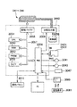
===制御回路の内部構造===
次に図8を参照してインクジェットプリンタの制御回路1050の内部構成について説明する。図8は、本実施の形態に係るインクジェットプリンタの制御回路1050の内部構成を示したブロック図である。
=== Internal structure of control circuit ===
Next, the internal configuration of the
図示するように、制御回路1050の内部には、CPU1051、PROM1052、RAM1053、周辺機器入出力部(PIO)1054、タイマ1055、駆動バッファ1056等が設けられている。
As shown in the figure, a
PIO1054には、操作パネル1011、パーソナルコンピュータPC、インクカートリッジの記憶素子MEとの接点MEC、キャリッジモータ1041、紙送りモータ1043、エンコーダ1047、及び送受信部1080が接続されている。駆動バッファ1056は、印字ヘッドIH1〜IH4にドット形成のためのオン・オフ信号を供給するバッファとして使用される。これらは互いにバス1057で接続され、相互にデータのやり取りが可能となっている。また、制御回路1050には、所定周波数で駆動波形を出力する発振器1058、及び発振器1058からの出力を印字ヘッドIH1〜IH4に所定のタイミングで分配する分配出力器1059も設けられている。
Connected to the
制御回路1050は、被印刷体1082が印刷セット位置に一時停止した際に、送受信部1080を介して、被印刷体1082の記憶素子1081に対しアクセスする。そして制御回路1050は、記憶素子1081から取得した情報を反映して、印刷処理を制御し、また、印刷結果に関する各種の情報を記憶素子1081に書き込む。
The
印刷実行時には、キャリッジモータ1041や紙送りモータ1043の動きと同期をとりながら、所定のタイミングでドットデータを駆動バッファ1056に出力する。記憶素子1081に対する読み取り処理、並びに記憶素子1081から取得した情報を利用した印刷処理、及び印刷結果に関する情報の書き込み処理の詳細ついては、後述する。
When printing is performed, dot data is output to the
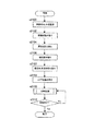
===インクジェットプリンタの動作===
次に、図9を参照して、本実施の形態に係るインクジェットプリンタ1010の動作について説明する。図9は、ある画像データの印刷実行時にインクジェットプリンタ1010の制御回路1050において実行される処理のフローチャートである。ここでは、送受信部1080は、紙検出器1063の付近の給紙路内上方に、設けられていることとする。
=== Operation of Inkjet Printer ===
Next, the operation of the
制御回路1050は、まず、紙検出器1063から被印刷体1082の位置情報を受信して、被印刷体1082が搬送位置決め手段1061、1062により印刷セット位置にセットされたことを認識する(ステップs1100)。
First, the
制御回路1050は、次に、送受信部1080を介して、記憶素子1081のメモリセル1817の読み取り領域1817Rに記録された各種情報の読取処理を、アドレスの先頭部から順次シリアルに実行し、取得した情報を一旦、RAM1053に格納する(ステップs1102)。各種情報とはすなわち、被印刷体1082の種類、厚さ、幅、製造年月日、LUTなどである。
Next, the
制御回路1050は、次に、送受信部1080を介して、メモリセル1817の書き込み領域1817Wに、印刷結果に関する各種情報の書き込み処理を行う。まず、印刷装置を特定するための情報の書き込みを行う(ステップs1104)。
Next, the
以降、順次、印刷対象である画像データを撮影したデジタルカメラを特定するための情報(ステップs1106)、印刷日付(ステップs1108)、印刷対象である画像データのファイル名やパス名などの情報(ステップs1110)、及び印刷対象である画像データそのもの(ステップs1112)の書き込みを行う。 Thereafter, information (step s1106) for specifying the digital camera that captured the image data to be printed (step s1106), the printing date (step s1108), and information such as the file name and path name of the image data to be printed (step) s1110) and the image data itself to be printed (step s1112) are written.
これらの情報を記憶素子1081に書き込んでおくことによって、後日同じ画像データを印刷し、同じ印刷結果を得たいという際に、色変換情報などの印刷装置毎に異なる印刷属性情報や、色補正などのデジタルカメラ毎に異なる画像処理情報、及び画像データの保存場所やファイル名などの情報を読み取って印刷制御に利用することができるので、記憶に頼ることなく容易に同じ印刷結果を再現することができる。また、印刷日付情報を読み取ることによって、時間経過に伴う印刷画像の画質劣化について調べることなどができる。
By writing these pieces of information in the
図9の説明に戻ると、次に制御回路1050は、印刷処理を行う(ステップs1114)。印刷処理は、基本的には公知の処理手順によって実行される。その際、RAM1053に格納した上記の各制御情報を読み出して、キャリッジモータ1041や、紙送りモータ1043、印刷ヘッドIH1〜4の駆動制御を行う。
Returning to the explanation of FIG. 9, the
最後に制御回路1050は、印刷の終了を待機し(ステップs1116:No)、印刷が終了したと判定すると(ステップs1116:Yes)、本ルーチンを終了する。
Finally, the
なお、本実施形態の様に、画像データそのものを被印刷体1082の記憶素子1081に書き込んでおいた場合は、後日これを何らかの読み取り装置にて読み取って印刷することができる。この場合、画像データがもともと保存されていたコンピュータがなくとも、被印刷体自体が画像データを保有しているので別のコンピュータ及び印刷装置を用いて簡単に出力することができる。例えば、インクジェットプリンタなどのプリンタを多種販売する店舗の店頭において、サンプル画像をデモ印刷する場合は、ある画像が印刷された被印刷体の画像データを読み取って様々なプリンタで出力することによって、コンピュータ本体などを準備せずとも同じデータによる印刷結果の比較を簡単に行うことができる。その際、読み取り装置は上記実施形態と同様に印刷装置の給紙路途中に設けられていてもよいが、非接触式の読み取りが可能な小型ハンディスキャナのようなものであってもよい。
Note that when the image data itself is written in the
また、以上の実施形態においては、インクジェットプリンタ1010にて被印刷体1082に対し印刷処理、及び画像データなどの書き込み処理を行い、後日、別の印刷装置にてこの画像データの読み取りを行い再印刷することとしたが、インクジェットプリンタ1010は、記憶素子1081への読み取りと書き込みの両方が可能な印刷装置であるので、後日再びインクジェットプリンタ1010にて被印刷体1082から画像データなどを読み取り、印刷してもよい。
In the above embodiment, the
===その他===
本発明は、カット紙に対して効果的に適用可能であるが、カット紙に限らず、ロール紙についても適用可能である。この場合は、ロール紙ユニットの芯部周囲に巻き付けられた紙等に素子を設ければよい。
=== Others ===
The present invention can be effectively applied to cut paper, but is not limited to cut paper and can also be applied to roll paper. In this case, an element may be provided on paper or the like wound around the core of the roll paper unit.
前述の実施の形態では、被印刷体の本体部として厚紙を例にとって説明したが、プラスチックボード、金属薄板等を用いてもよい。 In the above-described embodiment, the cardboard is used as an example of the main body of the printing material, but a plastic board, a metal thin plate, or the like may be used.
前述の実施形態に係るインクジェットプリンタと、コンピュータ本体、CRT等の表示装置、マウスやキーボード等の入力装置、フレキシブルドライブ装置、及び、CD−ROMドライブ装置を備えたコンピュータシステムも実現可能であり、このようにして実現されたコンピュータシステムは、システム全体として従来システムよりも優れたシステムとなる。 A computer system including the inkjet printer according to the above-described embodiment, a computer main body, a display device such as a CRT, an input device such as a mouse or a keyboard, a flexible drive device, and a CD-ROM drive device can also be realized. The computer system thus realized is a system superior to the conventional system as a whole system.
また、前述の実施形態に係るインクジェットプリンタに、コンピュータ本体、表示装置、入力装置、フレキシブルディスクドライブ装置、及び、CD−ROMドライブ装置がそれぞれ有する機能又は機構の一部を持たせてもよい。例えば、プリンタが、画像処理を行う画像処理部、各種の表示を行う表示部、及び、デジタルカメラ等により撮影された画像データを記録した記録メディアを着脱するための記録メディア着脱部を有する構成としてもよい。 In addition, the inkjet printer according to the above-described embodiment may have some of the functions or mechanisms that the computer main body, the display device, the input device, the flexible disk drive device, and the CD-ROM drive device have. For example, the printer includes an image processing unit that performs image processing, a display unit that performs various displays, and a recording medium attachment / detachment unit for attaching / detaching a recording medium that records image data captured by a digital camera or the like. Also good.
上記各実施の形態では、印刷装置としてインクジェットプリンタ1010を用いたが、カット紙などの単票メディアに対して印刷処理できる印刷装置であれば、これに限られることなく、例えば、モノクロプリンタ、レーザプリンタ、ファクシミリ等に適用しても良い。
In each of the above embodiments, the
また、上記各実施の形態では、記憶素子として、非接触ICチップと、金属皮膜をエッチングして形成された共振用コンデンサ及び平面状アンテナコイルを備えたものを用いたが、このような構成に限定されるものではなく、例えば共振用コンデンサは記憶素子の外部に接続されていてもよいし、ICチップとアンテナコイルが離れた場所にそれぞれ配設されて接続されている構成など様々な変形が考えられる。 In each of the above embodiments, the memory element includes a non-contact IC chip, a resonance capacitor formed by etching a metal film, and a planar antenna coil. For example, the resonance capacitor may be connected to the outside of the memory element, and various modifications such as a configuration in which the IC chip and the antenna coil are disposed and connected to each other are connected. Conceivable.
=第2実施形態=
===インクジェットプリンタの概略===
次に、本発明の主な適用対象である印刷装置としてのインクジェットプリンタの概略について説明する。図10は、インクジェットプリンタの概略的な外観を示した図である。
= Second Embodiment =
=== Outline of Inkjet Printer ===
Next, an outline of an ink jet printer as a printing apparatus to which the present invention is applied will be described. FIG. 10 is a diagram showing a schematic appearance of the ink jet printer.
ここでは、カラーインクジェットプリンタを示した。このカラープリンタ2010は、カラー画像の出力が可能なインクジェットプリンタであり、例えば、シアン(C)、マゼンタ(M)、イエロ(Y)、ブラック(K)の4色の色インクをカット紙などの被印刷体上に吐出してドットを形成することによって画像を形成するインクジェット方式のプリンタである。なお、色インクとして、上記4色に加えて、ライトシアン(薄いシアン、LC)、ライトマゼンタ(薄いマゼンタ、LM)、ダークイエロ(暗いイエロ、DY)を用いても良い。
Here, a color inkjet printer is shown. The
図10に示すように、カラープリンタ2010は、背面側上方から供給されたカット紙を前面から排出する給紙構造を備えている。プリンタ本体2010の前面には操作パネル2011、排紙部2012が備えられ、背面には給紙部2013が備えられている。操作パネル2011には、各種操作ボタン2111、表示ランプ2112が設けられている。排紙部2012は、不使用時に排紙口を塞ぐ排紙トレー2121が備えられている。
As shown in FIG. 10, the
給紙部2013には、図示していないカット紙を保持する給紙トレー2131が備えられている。なお、カット紙とは、予め所定の寸法に切断された紙であり、カラープリンタ2010によって切断されることのない単票の印刷メディアである。
The
===給紙機構の構成===
本実施形態のカラープリンタ2010は、特に、ストレートパスと呼ばれるもう1つの給紙経路(図10には示していない)を有する構成のものである。これは、厚紙などの一定の厚さや硬さを有する被印刷体を手差しにより供給する給紙機構である。このストレートパス機構では、CD−Rなどの変則的な寸法、形状の被印刷体に対しても、被印刷体搬送トレー(図示していない)に載置して供給することにより、被印刷体を切断することなく印刷を行うことが可能である。図11は、これら2つの給紙機構について説明するための、プリンタ2010の要部断面図である。
=== Configuration of Paper Feed Mechanism ===
The
カラープリンタ2010には、被印刷体に印刷を行う手段として、摺動軸2044に軸支され、摺動軸方向(主走査方向)に移動するキャリッジ2040が設けられており、このキャリッジ2040には、被印刷体にインクを吐出して印刷を行うヘッドIH1〜IH4が搭載されている。ヘッドIH1〜IH4と対向して、ヘッドIH1〜IH4のヘッド面と被印刷体とのギャップを規定するプラテン2042が設けられている。そして、キャリッジ2040を主走査方向に搬送し、被印刷体をキャリッジ2040とプラテン2042との間で副走査方向Yに間欠的に搬送しながら、ヘッドIH1〜IH4が被記録材にインクを吐出することによって、被印刷体に印刷が行われる。
The
給紙トレー2131は、例えば普通紙やフォト紙等のカット紙である被印刷体を供給することが可能な構成であり、被印刷体を自動供給するためのASF(オート・シート・フィーダー)が設けられている。ASFは、給紙トレー2131に設けられた給紙ローラ2132、及び図示していない分離パッドを有する自動給紙機構である。給紙ローラ2132は、略D形の横断面形状を有しており、ステッピング・モータ等の回転駆動力により回転制御される。そして、給紙ローラ2132の回転駆動力と分離パッドの摩擦抵抗によって、複数の被印刷体が一度に給紙されることを防ぐ。
The
そして、矢印Aで示した経路に沿ってASFにより自動給紙された被印刷体は、給紙ローラ2132より副走査方向Yの下流側に配設された被印刷体搬送位置決め手段により、印刷実行領域に向けて、所定の紙送り量で間欠的に搬送される。
Then, the printing medium automatically fed by the ASF along the path indicated by the arrow A is printed by the printing medium conveyance positioning unit disposed downstream of the
被印刷体を副走査方向Yに間欠的に搬送し、位置決めする搬送位置決め手段として、搬送駆動ローラ2061と搬送従動ローラ2062が設けられている。搬送駆動ローラ2061は、ステッピング・モータ等の紙送りモータにより回転制御され、被印刷体は搬送駆動ローラ2061の回転により副走査方向Yに搬送される。搬送従動ローラ2062は、複数の搬送従動ローラホルダ2621に軸支されている。被印刷体が搬送駆動ローラ2061の回転により搬送される際に、搬送従動ローラ2062は、従動して回転する。
A
また、給紙ローラ2132と搬送駆動ローラ2061との間には、従来技術において公知の技術による紙検出器2063が配設されている。紙検出器2063は、立位姿勢への自己復帰習性が付与され、かつ記録紙搬送方向にのみ回動し得るよう被印刷体の搬送経路内に突出する状態で枢支されたレバー2631を有する。このレバー2631の先端が被印刷体に押されることにより、レバー2631が回動し、それによって被印刷体が検出される構成である。紙検出器2063は、給紙ローラ2132より給紙された被印刷体の始端位置、及び終端位置を検出し、その検出位置に合わせて印刷領域が決定され、印刷が実行される。
Further, a
一方、印刷された被印刷体を排紙する手段として、排紙駆動ローラ2064と排紙従動ローラ2065が設けられている。排紙駆動ローラ2064は、ステッピング・モータ等の回転駆動力により回転制御され、排紙駆動ローラ2064の回転により、被印刷体は副走査方向Yに排紙される。排紙従動ローラ2065は、周囲に複数の歯を有し、各歯の先端が被印刷体の記録面に点接触するように鋭角的に尖っている歯付きローラであり、それぞれ、被印刷体が排紙駆動ローラ2064の回転により排紙される際に従動して回転する。
On the other hand, a
さらに、プリンタ2010には、上述したASFによる給紙経路(符号Aの矢印で示した経路)とは別に、記憶素子を埋設させた厚紙など、柔軟性の少ない被印刷体などを供給するための給紙路が設けられている。図中、この給紙路を符号Bの矢印で示している。そして、プリンタ2010は、この矢印Bの給紙路から給紙された被印刷体に対しても、前記ASFから給紙された被印刷体と同様に印刷を実行することができる。
Further, in addition to the above-described ASF paper feed path (path indicated by the arrow A), the
さらに、プリンタ2010は、図示していないが、搬送従動ローラレリース機構を備えている。被印刷体をセット位置にセットする際に、搬送従動ローラ2062を搬送駆動ローラ2061から離間させた状態(レリース状態)に保持し、被印刷体を給紙路に挿入して印刷セット位置にセットし、印刷セット位置への位置合わせ完了後に、そのレリース状態を解除し、搬送従動ローラ2062が搬送駆動ローラ2061によって付勢される状態に復帰する。ここで、被印刷体が印刷セット位置にセットされる際に、しばらく動作停止状態となるので、この一時停止状態を利用して、記憶素子付きの被印刷体に対しては記憶素子からの情報読み取りを行う。
Further, the
図示していないが、矢印Bの給紙路と矢印Aの給紙路との合流地点付近、すなわち紙検出器2063の付近の上方に、被印刷体の記憶素子から情報を読み取るための読み取り手段としての読み取りセンサが設けられている。読み取りセンサは、上記被印刷体が一時停止状態となる位置において、その記憶素子とちょうど対向する箇所に設けられている。読み取りセンサの構成や配置についての詳細は、後述する。
Although not shown in the drawing, reading means for reading information from the storage element of the printing medium near the merging point of the paper feeding path indicated by the arrow B and the paper feeding path indicated by the arrow A, that is, above the
なお、符号Bの矢印で示した経路に被印刷体を搬送する給紙機構(搬送手段)は、水平状態でセットされた被印刷体を、該水平状態を維持しつつ搬送するから、被印刷体の剛性が高い場合等であっても、該被印刷体に設けられた素子に記憶された情報を効果的に読み込むことが可能となる。 Note that the paper feeding mechanism (conveying means) that conveys the printing medium along the path indicated by the arrow B conveys the printing medium set in the horizontal state while maintaining the horizontal state. Even when the rigidity of the body is high, it is possible to effectively read the information stored in the element provided on the printing medium.
===被印刷体の構成===
図12は、本実施形態における被印刷体の斜視図である。この被印刷体2082は、本体が厚紙であり、矢印Bを給紙方向として本体の先端付近に記憶素子2081が埋設されている。前述のように、記憶素子2081は、被印刷体がY方向給紙路の途中で一時停止状態となる位置において、記憶素子2081と読み取りセンサ2080(図13)とがちょうど対向するように位置決めされる。記憶素子2081を埋設する位置としては、読み取りセンサ2080を設ける位置にも依存するが、厚紙の後端寄りであると、読み取りセンサ2080による読み取りの後で、再び前記セット位置まで被印刷体2082を戻す動作が必要となるので、先端付近とすることが好ましい。
=== Configuration of Printed Material ===
FIG. 12 is a perspective view of a printing medium in the present embodiment. This
記憶素子2081は、NAND型フラッシュROMなどのメモリセルを有する素子であり、アンテナとなるコイルや、制御部や記憶部を有するICチップから構成される、ごく小型かつ薄型のものである。0.5mmほどの厚さを有する厚紙などであれば容易に埋設することができる。また、この記憶素子2081は、非接触式の読み取りが可能なタイプのものである。従って、読み取りセンサ2080と記憶素子2081とが互いに接触する必要は無く、両者は間隙を有する。記憶素子2081は、読み取りセンサ2080から送信される搬送波を整流して必要な電力を生成する。なお、読み取りセンサ2080を、情報の読み取りだけでなく書き込みも可能な送受信手段とした場合は、印刷装置2010から記憶素子2081に様々な情報を書き込むことも可能である。
The
===記憶素子と読み取りセンサの構成===
次に、図13を参照して記憶素子2081と読み取りセンサ2080の構成について説明する。図13(a)は、記憶素子2081の構成を示す平面透視図である。記憶素子2081は、読み取りセンサ2080とのデータ送受信可能距離が20cm程度である、近接型の非接触式記憶素子である。全体としてごく小型かつ薄型で、片面に粘着性を持たせてシールとして対象物に貼着させることもできる。メモリタグなどと呼ばれ、多種市販されているものである。
=== Configuration of Storage Element and Reading Sensor ===
Next, the configuration of the
記憶素子2081は、非接触ICチップ2811と、金属皮膜をエッチングして形成された共振用コンデンサ2812及び平面状コイル2813とがプラスチックフィルム上に実装され、透明なカバーシートにより被覆されている。一方、平面図などは示さないが、読み取りセンサ2080は、記憶素子と同様のコイルアンテナ2801と、送受信回路2802とから構成され、電力の供給はプリンタ本体2010の電源ユニットから受ける。
In the
図13(b)は記憶素子2081及び読み取りセンサ2080の内部構成を示すブロック図である。読み取りセンサ2080は、アンテナコイル2801と、後述するプリンタ本体制御回路の周辺機器入出力部(PIO)2054(図17)に接続される送受信回路2802とから構成されている。記憶素子2081のICチップ2811は、整流器2814、信号解析部RF(Radio Frequency)2815、制御部2816、メモリセル2817から構成されている。メモリセル2817は、NAND型フラッシュROMなど電気的に読み書き可能なメモリである。
FIG. 13B is a block diagram showing the internal configuration of the
記憶素子2081のアンテナ2813と読み取りセンサ2080のアンテナ2801とは、互いに通信し合い、メモリセル2817に保存された情報の読み取り等を行う。また、読み取りセンサ2080の送受信回路2802で発生された高周波信号は、アンテナ2801を介して高周波磁界として誘起される。この高周波磁界は、記憶素子2081のアンテナ2813を介して吸収され、整流器2814で整流されてICチップ2811内の各回路を駆動する直流電力源となる。
The
===記憶素子に記憶されているデータ===
図14は、記憶素子2081のメモリセル2817におけるデータ配列を示した図である。これらのデータは全て、当該記憶素子2081が埋設される厚紙個々の属性を表している。またこれらのデータは、記憶素子自体の工場での製造時や、厚紙への埋設工程などにおいて、書き込み処理されることとすればよい。
=== Data stored in a storage element ===
FIG. 14 is a diagram showing a data array in the
書き込まれているデータは、アドレス毎に8ビット情報であり、被印刷体種類、被印刷体厚さ、被印刷体幅、被印刷体製造年月日、及び被印刷体LUTである。被印刷体種類は、被印刷体2082の素材(紙、プラスチック、皮、OHPシートなど)及び紙である場合はその光沢などに関する情報である。被印刷体厚さは、被印刷体2082の厚さを示す情報である。この情報を利用することにより、厚みのある被印刷体2082を印刷する際に、被印刷体2082の印刷セット状態における搬送従動ローラ2062と搬送駆動ローラ2061の離間(レリース状態)間隔を制御することとしてもよい。被印刷体幅は、被印刷体2082の幅を示す情報である。この情報により、A4サイズ、B5サイズといった用紙幅をいちいちプリンタドライバソフトにて設定しなくとも、自動的に制御される。被印刷体LUT(Look Up Table)とは、インデックスカラー方式のインデックス番号と、実際に表示する色の数値情報とを関連付けている色補正表のことである。個々の被印刷体ごとに異なるので、カラー画像の色彩を印刷において高品質に表現するためには重要な情報である。記憶素子2081には、上記の情報以外の情報が適宜含まれていてもよい。
The written data is 8-bit information for each address, and includes a printing medium type, a printing medium thickness, a printing medium width, a printing medium manufacturing date, and a printing medium LUT. The printing medium type is information on the material (paper, plastic, leather, OHP sheet, etc.) of the
===読み取りセンサの配置===
読み取りセンサ2080の配置について、本実施形態においては、矢印Aの給紙路と矢印Bの給紙路との合流地点付近、紙検出器2063の付近上方に設けられることとしているが、これに限定されるものではない。だが、下流側の印刷ヘッドIH1〜4へと被印刷体2082を搬送する搬送位置決め手段(搬送駆動ローラ2061及び搬送従動ローラ2062)よりも給紙の上流であることが好ましい。記憶素子2081に記憶された情報をプリンタ2010本体側で、印刷実行時における早い時点で読み込むことができるので、印刷制御の設定を正確に行うことができるからである。
=== Arrangement of reading sensor ===
Regarding the arrangement of the
なお、読み取りセンサ2080を、印刷ヘッドIH1〜4のいずれかの下面などに設けて、印刷ヘッドIH1〜4とともに移動できる構成としてもよい。このような構成であれば、被印刷体2082の幅がどのような寸法であっても、印刷ヘッドIH1〜4を走査方向に適切な位置まで移動させて読み取りを行うことによって、確実にデータを読み取ることが可能となる。
Note that the
上記いずれの場合においても、近接型記憶素子2081の送受信可能距離の範囲内で読み取り可能な位置に配置されることが好ましいのは言うまでも無い。また、いずれの場合も、読み取り動作時に、確実に読み取りが行われるために、被印刷体2082の動作を一時停止させることが好ましい。
In any of the above cases, it is needless to say that it is preferable that the
===キャリッジ周辺の構成===
次にインクジェットプリンタ2010内部のキャリッジ2040及びその周辺の構成について説明する。図15は、そのキャリッジ2040周辺の構成を示した斜視図である。
=== Configuration around the carriage ===
Next, the
図15に示すように、キャリッジ2040は、駆動ベルト2045によりプーリ2046を介してキャリッジモータ2041に接続され、摺動軸2044に案内されてプラテン2042に平行に移動するように駆動される。キャリッジ2040の印刷紙に対向する面には、ブラックインクを吐出するノズル列及びカラーインクを吐出するノズル列を有するヘッドIH1〜IH4が設けられ、各ノズルはインクカートリッジINC1、INC2からインクの供給を受けて印刷紙にインク滴を吐出し、文字や画像を印刷する。
As shown in FIG. 15, the
また、キャリッジ2040の非印字領域には、非印字時にヘッドIH1〜IH4のノズル開口を封止するためのキャッピング装置2025と、図示しないポンプモータを有するポンプユニット2026とが設けられている。キャリッジ2040が印字領域から非印字領域に移動すると、図示しないレバーにキャリッジ2040が当接して、キャッピング装置2025が上方に移動し、ヘッドIH1〜IH4を封止する。
In the non-printing area of the
ヘッドIH1〜IH4のノズル開口列に目詰まりが生じた場合や、インクカートリッジINC1、INC2の交換等を行ってヘッドIH1〜IH4から強制的にインクを吐出する場合は、ヘッドIH1〜IH4を封止した状態でポンプユニット2026を作動させ、ポンプユニット2026からの負圧により、ノズル開口列からインクを吸い出す。これにより、ノズル開口列の近傍に付着している塵埃や紙粉が洗浄され、さらにはヘッドIH1〜IH4内の気泡がインクとともにキャップ2027に排出される。
When clogging occurs in the nozzle opening rows of the heads IH1 to IH4, or when ink is forcibly ejected from the heads IH1 to IH4 by replacing the ink cartridges INC1 and INC2, the heads IH1 to IH4 are sealed. In this state, the
===インクジェットプリンタの内部構成===
次に、図16を参照してカラーインクジェットプリンタ2010の内部構成について説明する。図16は、本実施の形態に係るプリンタ2010の内部構成を示した図である。
=== Internal structure of inkjet printer ===
Next, the internal configuration of the
プリンタ2010は、図示するように、キャリッジ2040に搭載された印字ヘッドIH1〜IH4を駆動してインクの吐出及びドット形成を行う機構と、このキャリッジ2040をキャリッジモータ2041によってプラテン2042の軸方向に往復動させる機構と、給紙ユニット2131から供給されるカット紙2133や、矢印Bの給紙路から供給される被印刷体を紙送りモータ2043によって搬送する機構と、制御回路2050とを有している。
As shown in the figure, the
キャリッジ2040をプラテン2042の軸方向に往復動させる機構は、プラテン2042の軸と並行に架設され、キャリッジ2040を摺動可能に保持する摺動軸2044と、キャリッジモータ2041との間に無端の駆動ベルト2045を張設するプーリ2046等から構成されている。
A mechanism for reciprocating the
被印刷体を搬送する機構は、プラテン2042と、プラテン2042を回転させる紙送りモータ2043と、搬送駆動ローラ2061及び搬送従動ローラ2062(図11)と、紙送りモータ2043の回転をプラテン2042及び上記2つのローラ2061、2062に伝えるギヤ機構2048と、プラテン2042の回転角度を検出するエンコーダ2047と、紙検出器2063(図11)などを有している。また、紙検出器2063付近に設けられた読み取りセンサ2080が設けられている。
The mechanism for transporting the printing medium includes a
制御回路2050は、プリンタの操作パネル2011や読み取りセンサ2080、外部接続されるパーソナルコンピュータ等と信号をやり取りしつつ、紙送りモータ2043やキャリッジモータ2041、印字ヘッドIH1〜IH4の動きを適切に制御する。給紙ユニット2131や矢印Bのストレートパス給紙路から供給される被印刷体は、プラテン2042と搬送従動ローラ2062の間に挟み込まれるようにセットされ、プラテン2042の回転角度に応じて所定量ずつ搬送される。
The
キャリッジ2040にはインクカートリッジINC1とインクカートリッジINC2とが装着される。各インクカートリッジINC1、INC2には、インク残量等を記憶する記憶素子ME(図17)が備えられている。インクカートリッジINC1には黒(K)インクが収容され、インクカートリッジINC2には他のインク、すなわち、シアン(C)、マゼンタ(M)、イエロ(Y)の3色インクが収納されている。ライトシアン(LC)、ライトマゼンタ(LM)、ダークイエロ(DY)のインクも収納可能であることは既述の通りである。
An ink cartridge INC1 and an ink cartridge INC2 are mounted on the
===制御回路の内部構造===
次に図17を参照してインクジェットプリンタの制御回路2050の内部構成について説明する。図17は、本実施の形態に係るインクジェットプリンタの制御回路2050の内部構成を示したブロック図である。
=== Internal structure of control circuit ===
Next, the internal configuration of the
図示するように、制御回路2050の内部には、CPU2051、PROM2052、RAM2053、周辺機器入出力部(PIO)2054、タイマ2055、駆動バッファ2056等が設けられている。
As shown in the figure, a
PIO2054には、操作パネル2011、パーソナルコンピュータPC、インクカートリッジの記憶素子MEとの接点MEC、キャリッジモータ2041、紙送りモータ2043、エンコーダ2047、及び読み取りセンサ2080が接続されている。駆動バッファ2056は、印字ヘッドIH1〜IH4にドット形成のためのオン・オフ信号を供給するバッファとして使用される。これらは互いにバス2057で接続され、相互にデータのやり取りが可能となっている。また、制御回路2050には、所定周波数で駆動波形を出力する発振器2058、及び発振器2058からの出力を印字ヘッドIH1〜IH4に所定のタイミングで分配する分配出力器2059も設けられている。
Connected to the
制御回路2050は、被印刷体2082が印刷セット位置に一時停止した際に、読み取りセンサ2080を介して、被印刷体2082の記憶素子2081から情報を読み取る。そして制御回路2050は、記憶素子2081から取得した情報を反映して、印刷処理を制御する。印刷実行時には、キャリッジモータ2041や紙送りモータ2043の動きと同期をとりながら、所定のタイミングでドットデータを駆動バッファ2056に出力する。記憶素子2081に対する読み取り処理、並びに記憶素子2081から取得した情報を利用した印刷処理の詳細ついては、後述する。
The
===インクジェットプリンタの動作===
次に、図18を参照して、本実施の形態に係るインクジェットプリンタ2010の動作について説明する。図18は、印刷実行時にインクジェットプリンタ2010の制御回路2050において実行される処理のフローチャートである。ここでは、読み取りセンサ2080は、紙検出器2063の付近の給紙路内上方に、設けられていることとする。
=== Operation of Inkjet Printer ===
Next, the operation of the
制御回路2050は、まず、紙検出器2063から被印刷体2082の位置情報を受信して、被印刷体2082が搬送位置決め手段2061、2062により印刷セット位置にセットされたことを認識する(ステップs2100)。
First, the
制御回路2050は、次に、被印刷体2082の記憶素子2081に記録された各種情報の読取処理を、アドレスの先頭部から順次シリアルに実行し、取得した情報を一旦、RAM2053に格納する。まず、被印刷体の種類を読み取る(ステップs2102)。これにより、披印刷体2082の本体部が厚紙であるか、プラスチックボードであるか、厚紙である場合は更に、普通紙であるか、フォト用紙などの光沢紙であるか、等の情報を取得し、後の印刷処理ステップにおける制御情報とすることができる。
Next, the
次に制御回路2050は、被印刷体2082の厚さ(ステップs2104)、幅(ステップs2106)、製造年月日(ステップs2107)、LUT(ステップs2108)についての情報を順次読み取る。このうち、厚さに関する情報は、前記搬送位置決め手段(搬送駆動ローラ2061及び搬送従動ローラ2062)のレリース機構の制御情報とすることもできる。また、製造年月日に関する情報は、例えば被印刷体2082の種類によって品質保持期限があるときなどに、古いと判断した場合はユーザに対してその旨の警告画面を表示することもできる。これらの情報は、RAM2053に格納される。
Next, the
次に制御回路2050は、印刷処理を行う(ステップs2110)。印刷処理は、基本的には公知の処理手順によって実行される。その際、RAM2053に格納した上記の各制御情報を読み出して、キャリッジモータ2041や、紙送りモータ2043、印刷ヘッドIH1〜4の駆動制御を行う。
Next, the
最後に制御回路2050は、印刷の終了を待機し(ステップs2112:No)、印刷が終了したと判定すると(ステップs2112:Yes)、本ルーチンを終了する。
Finally, the
===その他===
以上、実施の形態に基づき本発明に係る印刷装置等を説明してきたが、上記した発明の実施の形態は、本発明の理解を容易にするためのものであり、本発明を限定するものではない。本発明は、その趣旨を逸脱することなく、変更、改良され得ると共に、本発明にはその等価物が含まれることはもちろんである。
=== Others ===
The printing apparatus and the like according to the present invention have been described above based on the embodiments. However, the above-described embodiments of the present invention are for facilitating understanding of the present invention and are not intended to limit the present invention. Absent. The present invention can be changed and improved without departing from the gist thereof, and the present invention includes the equivalents thereof.
本発明は、カット紙に対して効果的に適用可能であるが、カット紙に限らず、ロール紙についても適用可能である。この場合は、ロール紙ユニットの芯部周囲に巻き付けられた紙等に素子を設ければよい。 The present invention can be effectively applied to cut paper, but is not limited to cut paper and can also be applied to roll paper. In this case, an element may be provided on paper or the like wound around the core of the roll paper unit.
前述の実施の形態では、被印刷体の本体部として厚紙を例にとって説明したが、プラスチックボード、金属薄板等を用いてもよい。 In the above-described embodiment, the cardboard is used as an example of the main body of the printing material, but a plastic board, a metal thin plate, or the like may be used.
前述の実施形態に係るインクジェットプリンタと、コンピュータ本体、CRT等の表示装置、マウスやキーボード等の入力装置、フレキシブルドライブ装置、及び、CD−ROMドライブ装置を備えたコンピュータシステムも実現可能であり、このようにして実現されたコンピュータシステムは、システム全体として従来システムよりも優れたシステムとなる。 A computer system including the inkjet printer according to the above-described embodiment, a computer main body, a display device such as a CRT, an input device such as a mouse or a keyboard, a flexible drive device, and a CD-ROM drive device can also be realized. The computer system thus realized is a system superior to the conventional system as a whole system.
また、前述の実施形態に係るインクジェットプリンタに、コンピュータ本体、表示装置、入力装置、フレキシブルディスクドライブ装置、及び、CD−ROMドライブ装置がそれぞれ有する機能又は機構の一部を持たせてもよい。例えば、プリンタが、画像処理を行う画像処理部、各種の表示を行う表示部、及び、デジタルカメラ等により撮影された画像データを記録した記録メディアを着脱するための記録メディア着脱部を有する構成としてもよい。 In addition, the inkjet printer according to the above-described embodiment may have some of the functions or mechanisms that the computer main body, the display device, the input device, the flexible disk drive device, and the CD-ROM drive device have. For example, the printer includes an image processing unit that performs image processing, a display unit that performs various displays, and a recording medium attachment / detachment unit for attaching / detaching a recording medium that records image data captured by a digital camera or the like. Also good.
また、上記各実施の形態では、印刷装置としてインクジェットプリンタ2010を用いたが、カット紙などの単票メディアに対して印刷処理できる印刷装置であれば、これに限られることなく、例えば、モノクロプリンタ、レーザプリンタ、ファクシミリ等に適用しても良い。
In each of the above-described embodiments, the
また、上記各実施の形態では、記憶素子として、非接触ICチップと、金属皮膜をエッチングして形成された共振用コンデンサ及び平面状アンテナコイルを備えたものを用いたが、このような構成に限定されるものではなく、例えば共振用コンデンサは記憶素子の外部に接続されていてもよいし、ICチップとアンテナコイルが離れた場所にそれぞれ配設されて接続されている構成など様々な変形が考えられる。 In each of the above embodiments, the memory element includes a non-contact IC chip, a resonance capacitor formed by etching a metal film, and a planar antenna coil. For example, the resonance capacitor may be connected to the outside of the memory element, and various modifications such as a configuration in which the IC chip and the antenna coil are disposed and connected to each other are connected. Conceivable.
=第3実施形態=
===インクジェットプリンタの概略===
次に、本発明の主な適用対象である印刷装置としてのインクジェットプリンタの概略について説明する。図19は、インクジェットプリンタの概略的な外観を示した図である。
= Third embodiment =
=== Outline of Inkjet Printer ===
Next, an outline of an ink jet printer as a printing apparatus to which the present invention is applied will be described. FIG. 19 is a diagram showing a schematic appearance of the ink jet printer.
ここでは、カラーインクジェットプリンタを示した。このカラープリンタ3010は、カラー画像の出力が可能なインクジェットプリンタであり、例えば、シアン(C)、マゼンタ(M)、イエロ(Y)、ブラック(K)の4色の色インクをカット紙などの被印刷体上に吐出してドットを形成することによって画像を形成するインクジェット方式のプリンタである。なお、色インクとして、上記4色に加えて、ライトシアン(薄いシアン、LC)、ライトマゼンタ(薄いマゼンタ、LM)、ダークイエロ(暗いイエロ、DY)を用いても良い。
Here, a color inkjet printer is shown. The
図19に示すように、カラープリンタ3010は、背面側上方から供給されたカット紙を前面から排出する給紙構造を備えている。プリンタ本体3010の前面には操作パネル3011、排紙部3012が備えられ、背面には給紙部3013が備えられている。操作パネル3011には、各種操作ボタン3111、表示ランプ3112が設けられている。排紙部3012は、不使用時に排紙口を塞ぐ排紙トレー3121が備えられている。給紙部3013には、図示していないカット紙を保持する給紙トレー3131が備えられている。なお、カット紙とは、予め所定の寸法に切断された紙であり、カラープリンタ3010によって切断されることのない単票の印刷メディアである。
As shown in FIG. 19, the
===給紙機構の構成===
本実施形態のカラープリンタ3010は、特に、ストレートパスと呼ばれるもう1つの給紙経路(図19には示していない)を有する構成のものである。これは、厚紙などの一定の厚さや硬さを有する被印刷体を手差しにより供給する給紙機構である。このストレートパス機構では、CD−Rなどの変則的な寸法、形状の被印刷体に対しても、被印刷体搬送トレー(図示していない)に載置して供給することにより、被印刷体を切断することなく印刷を行うことが可能である。図20は、これら2つの給紙機構について説明するための、プリンタ3010の要部断面図である。
=== Configuration of Paper Feed Mechanism ===
The
カラープリンタ3010には、被印刷体に印刷を行う手段として、摺動軸3044に軸支され、摺動軸方向(主走査方向)に移動するキャリッジ3040が設けられており、このキャリッジ3040には、被印刷体にインクを吐出して印刷を行うヘッドIH1〜IH4が搭載されている。ヘッドIH1〜IH4と対向して、ヘッドIH1〜IH4のヘッド面と被印刷体とのギャップを規定するプラテン3042が設けられている。そして、キャリッジ3040を主走査方向に搬送し、被印刷体をキャリッジ3040とプラテン3042との間で副走査方向Yに間欠的に搬送しながら、ヘッドIH1〜IH4が被印刷体にインクを吐出することによって、被印刷体に印刷が行われる。
The
給紙トレー3131は、例えば普通紙やフォト紙等のカット紙である被印刷体を供給することが可能な構成であり、被印刷体を自動供給するためのASF(オート・シート・フィーダー)が設けられている。ASFは、給紙トレー3131に設けられた給紙ローラ3132、及び図示していない分離パッドを有する自動給紙機構である。給紙ローラ3132は、略D形の横断面形状を有しており、ステッピング・モータ等の回転駆動力により回転制御される。そして、給紙ローラ3132の回転駆動力と分離パッドの摩擦抵抗によって、複数の被印刷体が一度に給紙されることを防ぐ。
The
そして、矢印Aで示した経路に沿ってASFにより自動給紙された被印刷体は、給紙ローラ3132より副走査方向Yの下流側に配設された被印刷体搬送位置決め手段により、印刷実行領域に向けて、所定の紙送り量で間欠的に搬送される。
Then, the printing medium automatically fed by the ASF along the path indicated by the arrow A is printed by the printing medium conveyance positioning unit disposed downstream of the
被印刷体を副走査方向Yに間欠的に搬送し、位置決めする搬送位置決め手段として、搬送駆動ローラ3061と搬送従動ローラ3062が設けられている。搬送駆動ローラ3061は、ステッピング・モータ等の紙送りモータにより回転制御され、被印刷体は搬送駆動ローラ3061の回転により副走査方向Yに搬送される。搬送従動ローラ3062は、複数の搬送従動ローラホルダ3621に軸支されている。被印刷体が搬送駆動ローラ3061の回転により搬送される際に、搬送従動ローラ3062は、従動して回転する。
A transport driving roller 3061 and a transport driven roller 3062 are provided as transport positioning means for transporting and positioning the printing medium intermittently in the sub-scanning direction Y. The conveyance drive roller 3061 is rotationally controlled by a paper feed motor such as a stepping motor, and the printing medium is conveyed in the sub-scanning direction Y by the rotation of the conveyance drive roller 3061. The conveyance driven roller 3062 is pivotally supported by a plurality of conveyance driven
また、給紙ローラ3132と搬送駆動ローラ3061との間には、紙検出器3063が設けられている。紙検出器3063は、立位姿勢への自己復帰習性が付与され、かつ記録紙搬送方向にのみ回動し得るよう被印刷体の搬送経路内に突出する状態で枢支されたレバー3631を有する。このレバー3631の先端が被印刷体に押されることにより、レバー3631が回動し、それによって被印刷体が検出される構成である。紙検出器3063は、給紙ローラ3132より給紙された被印刷体の始端位置、及び終端位置を検出し、その検出位置に合わせて印刷領域が決定され、印刷が実行される。
A
一方、印刷された被印刷体を排紙する手段として、排紙駆動ローラ3064と排紙従動ローラ3065が設けられている。排紙駆動ローラ3064は、ステッピング・モータ等の回転駆動力により回転制御され、排紙駆動ローラ3064の回転により、被記録材は副走査方向Yに排紙される。排紙従動ローラ3065は、周囲に複数の歯を有し、各歯の先端が被印刷体の記録面に点接触するように鋭角的に尖っている歯付きローラであり、それぞれ、被印刷体が排紙駆動ローラ3064の回転により排紙される際に従動して回転する。
On the other hand, a
さらに、プリンタ3010には、上述したASFによる給紙経路(符号Aの矢印で示した経路)とは別に、記憶素子を埋設させた厚紙など、柔軟性の少ない被印刷体などを供給するための給紙路が設けられている。図中、この給紙路を符号Bの矢印で示している。そして、プリンタ3010は、この矢印Bの給紙路から給紙された被印刷体に対しても、前記ASFから給紙された被印刷体と同様に印刷を実行することができる。
Further, in addition to the ASF paper feed path (the path indicated by the arrow A), the
さらに、プリンタ3010は、図示していないが、搬送従動ローラレリース機構を備えている。被印刷体をセット位置にセットする際に、搬送従動ローラ3062を搬送駆動ローラ3061から離間させた状態(レリース状態)に保持し、被印刷体を給紙路に挿入して印刷セット位置にセットし、印刷セット位置への位置合わせ完了後に、そのレリース状態を解除し、搬送従動ローラ3062が搬送駆動ローラ3061によって付勢される状態に復帰する。ここで、被印刷体が印刷セット位置にセットされる際に、しばらく動作停止状態となるので、この一時停止状態を利用して、記憶素子付きの被印刷体に対しては、記憶素子への情報読み書きを行う。
Further, the
図示していないが、矢印Bの給紙路と矢印Aの給紙路との合流地点付近、すなわち紙検出器3063の付近の上方に、被印刷体の記憶素子に対する読み取り/書き取り手段としての送受信部が設けられている。送受信部は、上記被印刷体が一時停止状態となる位置において、その記憶素子とちょうど対向する箇所に設けられている。送受信部の構成や配置についての詳細は、後述する。
Although not shown, transmission / reception as read / write means for the storage element of the printing medium is performed near the junction of the paper feed path indicated by the arrow B and the paper feed path indicated by the arrow A, that is, above the
なお、符号Bの矢印で示した経路に被印刷体を搬送する給紙機構(搬送手段)は、水平状態でセットされた被印刷体を、該水平状態を維持しつつ搬送するから、被印刷体の剛性が高い場合等であっても、該被印刷体に設けられた素子に対して効果的に情報を書き込むこと又は情報を読み込むことが可能となる。 Note that the paper feeding mechanism (conveying means) that conveys the printing medium along the path indicated by the arrow B conveys the printing medium set in the horizontal state while maintaining the horizontal state. Even when the rigidity of the body is high, information can be effectively written into or read from the elements provided on the printing medium.
===被印刷体の構成===
図21は、本実施形態における被印刷体の斜視図である。この被印刷体3082は、本体が厚紙であり、矢印Bを給紙方向として本体の先端付近に記憶素子3081が埋設されている。前述のように、記憶素子3081は、被印刷体がY方向給紙路の途中で一時停止状態となる位置において、記憶素子3081と印刷装置に設けられた前記送受信部3080(図22)とがちょうど対向するように位置決めされる。記憶素子3081を埋設する位置としては、送受信部3080を設ける位置にも依存するが、厚紙の後端寄りであると、送受信部3080による読み取りの後で、再び前記セット位置まで被印刷体3082を戻す動作が必要となるので、先端付近とすることが好ましい。
=== Configuration of Printed Material ===
FIG. 21 is a perspective view of a printing medium in the present embodiment. The printed
記憶素子3081は、NAND型フラッシュROMなどのメモリセルを有する素子であり、アンテナとなるコイルや、制御部や記憶部を有するICチップから構成される、ごく小型かつ薄型のものである。0.5mmほどの厚さを有する厚紙などであれば容易に埋設することができる。また、この記憶素子3081は、非接触式の読み取り/書き込みが可能なタイプのものである。従って、送受信部3080と記憶素子3081とが互いに接触する必要は無く、両者は間隙を有する。記憶素子3081は、送受信部3080から送信される搬送波を整流して必要な電力を生成する。
The
===記憶素子と送受信部の構成===
次に、図22を参照して記憶素子3081と送受信部3080の構成について説明する。
=== Configuration of Storage Element and Transmission / Reception Unit ===
Next, the configuration of the
図22(a)は、記憶素子3081の構成を示す平面透視図である。記憶素子3081は、送受信部とのデータ送受信可能距離が10mm程度である、近接型の非接触式記憶素子である。全体としてごく小型かつ薄型で、片面に粘着性を持たせてシールとして対象物に貼着させることもできる。メモリタグなどと呼ばれ、多種市販されているものである。
FIG. 22A is a plan perspective view showing the configuration of the
記憶素子3081は、非接触ICチップ3811と、金属皮膜をエッチングして形成された共振用コンデンサ3812及び平面状コイル3813とがプラスチックフィルム上に実装され、透明なカバーシートにより被覆されている。一方、平面図などは示さないが、送受信部3080は、記憶素子と同様のコイルアンテナ3801と、送受信回路3802とから構成され、電力の供給はプリンタ本体3010の電源ユニットから受ける。
In the
図22(b)は記憶素子3081及び送受信部3080の内部構成を示すブロック図である。送受信部3080は、アンテナコイル3801と、後述するプリンタ本体制御回路の周辺機器入出力部(PIO)3054(図26)に接続される送受信回路3802とから構成されている。記憶素子3081のICチップ3811は、整流器3814、信号解析部RF(Radio Frequency)3815、制御部3816、メモリセル3817から構成されている。メモリセル3817は、NAND型フラッシュROMなど電気的に読み書き可能なメモリである。
FIG. 22B is a block diagram illustrating the internal configuration of the
記憶素子3081のアンテナ3813と送受信部3080のアンテナ3801とは、互いに通信し合い、メモリセル3817に保存された情報の読み書きを行う。また、送受信部3080の送受信回路3802で発生された高周波信号は、アンテナ3801を介して高周波磁界として誘起される。この高周波磁界は、記憶素子3081のアンテナ3813を介して吸収され、整流器3814で整流されてICチップ3811内の各回路を駆動する直流電力源となる。
The
===記憶素子に記憶されているデータ===
図23は、記憶素子3081のメモリセル3817におけるデータ配列を示した図である。メモリセル3817の領域は、被印刷体の属性情報が書き込まれた読み取り領域3817Rと、印刷結果に関する情報が書き込まれる書き込み領域3817Wとから成っている。
=== Data stored in a storage element ===
FIG. 23 is a diagram showing a data array in the
読み取り領域3817R(アドレス:00H〜04H)のデータは、当該記憶素子3081が埋設される厚紙個々の属性を表している。またこれらのデータは、記憶素子3081自体の工場での製造時や、厚紙への埋設工程などにおいて、書き込み処理されることとすればよい。
Data in the
読み取り領域3817Rの各データは、アドレス毎に8ビット情報であり、被印刷体種類、被印刷体厚さ、被印刷体幅、被印刷体製造年月日、及び被印刷体LUTである。被印刷体種類は、被印刷体3082の素材(紙、プラスチック、皮、OHPシートなど)及び紙である場合はその光沢などに関する情報である。被印刷体厚さは、被印刷体3082の厚さを示す情報である。この情報を利用することにより、厚みのある被印刷体3082を印刷する際に、被印刷体3082の印刷セット状態における搬送従動ローラ3062と搬送駆動ローラ3061の離間(レリース状態)間隔を制御することとしてもよい。被印刷体幅は、被印刷体3082の幅を示す情報である。この情報により、A4サイズ、B5サイズといった用紙幅をいちいちプリンタドライバソフトにて設定しなくとも、自動的に制御される。被印刷体LUT(Look Up Table)とは、インデックスカラー方式のインデックス番号と、実際に表示する色の数値情報とを関連付けている色補正表のことである。個々の被印刷体ごとに異なるので、カラー画像の色彩を印刷において高品質に表現するためには重要な情報である。以上示したデータ以外にも、被印刷体3082の属性に関する様々な情報が適宜含まれていてもよい。このように、種々の情報を読み取り領域3817Rに持たせることは有用であるが、かかる読み取り領域3817Rを設けずに、メモリセル3817に、印刷結果に関する情報が書き込まれる書き込み領域3817Wのみを設けてもよい。
Each piece of data in the
書き込み領域3817W(アドレス:05H以下)には、デジタルカメラ、デジタルビデオ等の各種撮影装置による画像データの生成が行われた際の撮影条件が、プリンタ3010によって書き込まれる。撮影条件としては、画像データの生成が行われた年月日を特定するための情報、デジタルカメラの機種を特定するための情報、撮影時におけるシャッター速度を特定するための情報、撮影時の絞り値を特定するための情報、デジタルカメラのISO感度相当値を特定するための情報、撮影時にフラッシュを使用したか否かを特定するための情報、及び、当該被印刷体3082に印刷された画像データそのものなどがある。また、デジタルカメラの画素数や音声データなども撮影条件として適宜書き込まれる。
In the
これらの情報やデータを書き込み領域3817Wに書き込んでおくことにより、デジタルカメラ等の撮影装置による画像データの生成が行われた際の撮影条件を被印刷体に印刷しなくとも、後日撮影条件を容易に知ることができる。
By writing these information and data in the
なお、読み取り領域3817R、及び書き込み領域3817Wの各アドレスに格納される情報は、必要に応じて8ビットよりも大きいこととしてもよい。また、画像データは通常相当の大きさを有するので、適宜あらかじめ相当の大きさ分のアドレスを確保しておくことが好ましい。
Note that the information stored in each address of the
===送受信部の配置===
送受信部3080の配置について、本実施形態においては、矢印Aの給紙路と矢印Bの給紙路との合流地点付近、紙検出器3063の付近上方に設けられることとしているが、これに限定されるものではない。
=== Arrangement of Transmission / Reception Units ===
With regard to the arrangement of the transmission /
送受信部3080は、被印刷体の搬送方向において、印刷ヘッドIH1〜4よりも上流側に設けられていることが好ましい。なぜなら、送受信部3080を、被印刷体の搬送方向において、送受信部3080よりも上流側に設けることにより、印刷ヘッドIH1〜4によるインク吐出が行われて印刷が実行される前に、素子に対して情報を書き込むことが可能となるからである。
The transmission /
より好ましくは、被印刷体3082を搬送する搬送位置決め手段(搬送駆動ローラ3061及び搬送従動ローラ3062)よりも給紙の上流であることが好ましい。記憶素子3081に記憶された情報をプリンタ3010本体側で、印刷実行時における早い時点で読み込むことができるので、印刷制御の設定を正確に行うことができるからである。
More preferably, it is more upstream of the paper feed than the conveyance positioning means (conveyance driving roller 3061 and conveyance driven roller 3062) for conveying the
また、記憶素子3081への書き込み処理も、同じ位置において読み取り処理に続けて行うこととすればよい。すなわち、被印刷体がプリンタ3010に対して所定の位置に位置した際に、素子に対する情報の書き込みが行われ、該位置において、該素子に記憶された情報の読み込みも可能であることとしてもよい。このように構成することにより、被印刷体がプリンタ3010に対して所定の位置に位置した状態で、素子に対する情報の書き込み、及び、読み込みがともに可能となる。
Further, the writing process to the
なお、送受信部3080を、印刷ヘッドIH1〜4のいずれかの下面などに設けて、印刷ヘッドIH1〜4とともに移動できる構成としてもよい。このような構成であれば、被印刷体3082の幅がどのような寸法であっても、印刷ヘッドIH1〜4を走査方向に適切な位置まで移動させて通信することによって、確実に送受信することが可能となる。
Note that the transmission /
上記いずれの場合においても、近接型記憶素子3081の送受信可能距離の範囲内で通信できる位置に配置されることが好ましいのは言うまでも無い。また、いずれの場合も、読み書き動作時に、確実に通信が行われるために、被印刷体3082の動作を一時停止させることが好ましい。
In any of the above cases, it is needless to say that it is preferable that the
===キャリッジ周辺の構成===
次にインクジェットプリンタ3010内部のキャリッジ3040及びその周辺の構成について説明する。図24は、そのキャリッジ3040周辺の構成を示した斜視図である。
=== Configuration around the carriage ===
Next, the
図24に示すように、キャリッジ3040は、駆動ベルト3045によりプーリ3046を介してキャリッジモータ3041に接続され、摺動軸3044に案内されてプラテン3042に平行に移動するように駆動される。キャリッジ3040の印刷紙に対向する面には、ブラックインクを吐出するノズル列及びカラーインクを吐出するノズル列を有するヘッドIH1〜IH4が設けられ、各ノズルはインクカートリッジINC1、INC2からインクの供給を受けて印刷紙にインク滴を吐出し、文字や画像を印刷する。
As shown in FIG. 24, the
また、キャリッジ3040の非印字領域には、非印字時にヘッドIH1〜IH4のノズル開口を封止するためのキャッピング装置3025と、図示しないポンプモータを有するポンプユニット3026とが設けられている。キャリッジ3040が印字領域から非印字領域に移動すると、図示しないレバーにキャリッジ3040が当接して、キャッピング装置3025が上方に移動し、ヘッドIH1〜IH4を封止する。
In the non-printing area of the
ヘッドIH1〜IH4のノズル開口列に目詰まりが生じた場合や、インクカートリッジINC1、INC2の交換等を行ってヘッドIH1〜IH4から強制的にインクを吐出する場合は、ヘッドIH1〜IH4を封止した状態でポンプユニット3026を作動させ、ポンプユニット3026からの負圧により、ノズル開口列からインクを吸い出す。これにより、ノズル開口列の近傍に付着している塵埃や紙粉が洗浄され、さらにはヘッドIH1〜IH4内の気泡がインクとともにキャップ3027に排出される。
When clogging occurs in the nozzle opening rows of the heads IH1 to IH4, or when ink is forcibly ejected from the heads IH1 to IH4 by replacing the ink cartridges INC1 and INC2, the heads IH1 to IH4 are sealed. In this state, the
===インクジェットプリンタの内部構成===
次に、図25を参照してカラーインクジェットプリンタ3010の内部構成について説明する。図25は、本実施の形態に係るプリンタ3010の内部構成を示した図である。
=== Internal structure of inkjet printer ===
Next, the internal configuration of the
プリンタ3010は、図示するように、キャリッジ3040に搭載された印字ヘッドIH1〜IH4を駆動してインクの吐出及びドット形成を行う機構と、このキャリッジ3040をキャリッジモータ3041によってプラテン3042の軸方向に往復動させる機構と、給紙ユニット3131から供給されるカット紙や、矢印Bの給紙路から供給される被印刷体3082を紙送りモータ3043によって搬送する機構と、制御回路3050とを有している。
As shown in the figure, the
キャリッジ3040をプラテン3042の軸方向に往復動させる機構は、プラテン3042の軸と並行に架設され、キャリッジ3040を摺動可能に保持する摺動軸3044と、キャリッジモータ3041との間に無端の駆動ベルト3045を張設するプーリ3046等から構成されている。
The mechanism for reciprocating the
被印刷体を搬送する機構は、プラテン3042と、プラテン3042を回転させる紙送りモータ3043と、搬送駆動ローラ3061及び搬送従動ローラ3062(図20)と、紙送りモータ3043の回転をプラテン3042及び上記2つのローラ3061、3062に伝えるギヤ機構3048と、プラテン3042の回転角度を検出するエンコーダ3047と、紙検出器3063(図20)などを有している。また、紙検出器3063付近に設けられた送受信部3080が設けられている。
A mechanism for transporting the printing medium includes a
制御回路3050は、プリンタの操作パネル3011や送受信部3080、外部接続されるパーソナルコンピュータ等と信号をやり取りしつつ、紙送りモータ3043やキャリッジモータ3041、印字ヘッドIH1〜IH4の動きを適切に制御する。給紙ユニット3131や矢印Bのストレートパス給紙路から供給される被印刷体は、プラテン3042と搬送従動ローラ3062の間に挟み込まれるようにセットされ、プラテン3042の回転角度に応じて所定量ずつ搬送される。
The
キャリッジ3040にはインクカートリッジINC1とインクカートリッジINC2とが装着される。各インクカートリッジINC1、INC2には、インク残量等を記憶する記憶素子ME(図26)が備えられている。インクカートリッジINC1には黒(K)インクが収容され、インクカートリッジINC2には他のインク、すなわち、シアン(C)、マゼンタ(M)、イエロ(Y)の3色インクが収納されている。ライトシアン(LC)、ライトマゼンタ(LM)、ダークイエロ(DY)のインクも収納可能であることは既述の通りである。
An ink cartridge INC1 and an ink cartridge INC2 are mounted on the
===制御回路の内部構造===
次に図26を参照してインクジェットプリンタの制御回路3050の内部構成について説明する。図26は、本実施の形態に係るインクジェットプリンタの制御回路3050の内部構成を示したブロック図である。
=== Internal structure of control circuit ===
Next, the internal configuration of the
図示するように、制御回路3050の内部には、CPU3051、PROM3052、RAM3053、周辺機器入出力部(PIO)3054、タイマ3055、駆動バッファ3056等が設けられている。
As shown in the figure, a
PIO3054には、操作パネル3011、パーソナルコンピュータPC、インクカートリッジの記憶素子MEとの接点MEC、キャリッジモータ3041、紙送りモータ3043、エンコーダ3047、及び送受信部3080が接続されている。駆動バッファ3056は、印字ヘッドIH1〜IH4にドット形成のためのオン・オフ信号を供給するバッファとして使用される。これらは互いにバス3057で接続され、相互にデータのやり取りが可能となっている。また、制御回路3050には、所定周波数で駆動波形を出力する発振器3058、及び発振器3058からの出力を印字ヘッドIH1〜IH4に所定のタイミングで分配する分配出力器3059も設けられている。
Connected to the
制御回路3050は、被印刷体3082が印刷セット位置に一時停止した際に、送受信部3080を介して、被印刷体3082の記憶素子3081に対しアクセスする。そして制御回路3050は、記憶素子3081から取得した情報を反映して、印刷処理を制御し、また、印刷結果に関する各種の情報を記憶素子3081に書き込む。
The
印刷実行時には、キャリッジモータ3041や紙送りモータ3043の動きと同期をとりながら、所定のタイミングでドットデータを駆動バッファ3056に出力する。記憶素子3081に対する読み取り処理、並びに記憶素子3081から取得した情報を利用した印刷処理、及び印刷結果に関する情報の書き込み処理の詳細ついては、後述する。
When printing is performed, dot data is output to the
===インクジェットプリンタの動作===
次に、図27を参照して、本実施の形態に係るインクジェットプリンタ3010の動作について説明する。図27は、ある画像データの印刷実行時にインクジェットプリンタ3010の制御回路3050において実行される処理のフローチャートである。ここでは、送受信部3080は、紙検出器3063の付近の給紙路内上方に、設けられていることとする。
=== Operation of Inkjet Printer ===
Next, the operation of the
制御回路3050は、まず、紙検出器3063から被印刷体3082の位置情報を受信して、被印刷体3082が搬送位置決め手段3061、3062により印刷セット位置にセットされたことを認識する(ステップs3100)。
First, the
制御回路3050は、次に、送受信部3080を介して、記憶素子3081のメモリセル3817の読み取り領域3817Rに記録された各種情報の読取処理を、アドレスの先頭部から順次シリアルに実行し、取得した情報を一旦、RAM3053に格納する(ステップs3102)。各種情報とはすなわち、被印刷体3082の種類、厚さ、幅、製造年月日、LUTなどである。なお、前述したように、メモリセル3817に読み取り領域3817Rを設けない構成も可能であり、そのような構成の場合には、このステップ(s3102)を省略すればよい。
Next, the
制御回路3050は、次に、送受信部3080を介して、メモリセル3817の書き込み領域3817W(アドレス:05H以下)に、デジタルカメラによる画像データの生成が行われた際の撮影条件を書き込む。詳しくは、画像データの生成が行われた年月日を特定するための情報の書き込み処理(s3104)、デジタルカメラの機種を特定するための情報の書き込み処理(s3106)、撮影時におけるシャッター速度を特定するための情報の書き込み処理(s3108)、撮影時の絞り値を特定するための情報の書き込み処理(s3110)、デジタルカメラのISO感度相当値を特定するための情報の書き込み処理(s3112)、撮影時にフラッシュを使用したか否かを特定するための情報の書き込み処理(s3114)、及び、当該被印刷体3082に印刷された画像データそのものの書き込み処理(s3116)が行われる。なお、これらの書き込み処理(s3104〜s3116)の順番は適宜変更してもかまわない。
Next, the
これらの情報やデータを書き込み領域3817Wに書き込んでおくことにより、デジタルカメラ等の撮影装置による画像データの生成が行われた際の撮影条件を被印刷体に印刷しなくとも、後日撮影条件を容易に知ることができる。
By writing these information and data in the
図27の説明に戻ると、次に制御回路3050は、印刷処理を行う(ステップs3118)。印刷処理は、基本的には公知の処理手順によって実行される。その際、RAM3053に格納した上記の各制御情報を読み出して、キャリッジモータ3041や、紙送りモータ3043、印刷ヘッドIH1〜4の駆動制御を行う。
Returning to the description of FIG. 27, the
最後に制御回路3050は、印刷の終了を待機し(ステップs3120:No)、印刷が終了したと判定すると(ステップs3120:Yes)、本ルーチンを終了する。
Finally, the
なお、本実施形態の様に、画像データそのものを被印刷体3082の記憶素子3081に書き込んでおいた場合は、後日これを何らかの読み取り装置にて読み取って印刷することができる。この場合、画像データがもともと保存されていたコンピュータがなくとも、被印刷体自体が画像データを保有しているので別のコンピュータ及び印刷装置を用いて簡単に出力することができる。例えば、インクジェットプリンタなどのプリンタを多種販売する店舗の店頭において、サンプル画像をデモ印刷する場合は、ある画像が印刷された被印刷体の画像データを読み取って様々なプリンタで出力することによって、コンピュータ本体などを準備せずとも同じデータによる印刷結果の比較を簡単に行うことができる。その際、読み取り装置は上記実施形態と同様に印刷装置の給紙路途中に設けられていてもよいが、非接触式の読み取りが可能な小型ハンディスキャナのようなものであってもよい。
Note that when the image data itself is written in the
また、インクジェットプリンタ3010にて被印刷体3082に対し印刷処理、及び画像データなどの書き込み処理を行い、後日別の印刷装置にてこの画像データの読み取りを行い再印刷することの他、インクジェットプリンタ3010は、記憶素子3081への読み取りと書き込みの両方が可能な印刷装置であるので、後日再びインクジェットプリンタ3010にて被印刷体3082から画像データなどを読み取り、印刷してもよい。
In addition, the
===その他===
以上、実施の形態に基づき本発明に係る印刷装置等を説明してきたが、上記した発明の実施の形態は、本発明の理解を容易にするためのものであり、本発明を限定するものではない。本発明は、その趣旨を逸脱することなく、変更、改良され得ると共に、本発明にはその等価物が含まれることはもちろんである。
=== Others ===
The printing apparatus and the like according to the present invention have been described above based on the embodiments. However, the above-described embodiments of the present invention are for facilitating understanding of the present invention and are not intended to limit the present invention. Absent. The present invention can be changed and improved without departing from the gist thereof, and the present invention includes the equivalents thereof.
本発明は、カット紙に対して効果的に適用可能であるが、カット紙に限らず、ロール紙についても適用可能である。この場合は、ロール紙ユニットの芯部周囲に巻き付けられた紙等に素子を設ければよい。 The present invention can be effectively applied to cut paper, but is not limited to cut paper and can also be applied to roll paper. In this case, an element may be provided on paper or the like wound around the core of the roll paper unit.
前述の実施の形態では、被印刷体の本体部として厚紙を例にとって説明したが、プラスチックボード、金属薄板等を用いてもよい。 In the above-described embodiment, the cardboard is used as an example of the main body of the printing material, but a plastic board, a metal thin plate, or the like may be used.
前述の実施形態に係るインクジェットプリンタと、コンピュータ本体、CRT等の表示装置、マウスやキーボード等の入力装置、フレキシブルドライブ装置、及び、CD−ROMドライブ装置を備えたコンピュータシステムも実現可能であり、このようにして実現されたコンピュータシステムは、システム全体として従来システムよりも優れたシステムとなる。 A computer system including the inkjet printer according to the above-described embodiment, a computer main body, a display device such as a CRT, an input device such as a mouse or a keyboard, a flexible drive device, and a CD-ROM drive device can also be realized. The computer system thus realized is a system superior to the conventional system as a whole system.
また、前述の実施形態に係るインクジェットプリンタに、コンピュータ本体、表示装置、入力装置、フレキシブルディスクドライブ装置、及び、CD−ROMドライブ装置がそれぞれ有する機能又は機構の一部を持たせてもよい。例えば、プリンタが、画像処理を行う画像処理部、各種の表示を行う表示部、及び、デジタルカメラ等により撮影された画像データを記録した記録メディアを着脱するための記録メディア着脱部を有する構成としてもよい。 In addition, the inkjet printer according to the above-described embodiment may have some of the functions or mechanisms that the computer main body, the display device, the input device, the flexible disk drive device, and the CD-ROM drive device have. For example, the printer includes an image processing unit that performs image processing, a display unit that performs various displays, and a recording medium attachment / detachment unit for attaching / detaching a recording medium that records image data captured by a digital camera or the like. Also good.
上記各実施の形態では、印刷装置としてインクジェットプリンタ3010を用いたが、カット紙などの単票メディアに対して印刷処理できる印刷装置であれば、これに限られることなく、例えば、モノクロプリンタ、レーザプリンタ、ファクシミリ等に適用しても良い。
In each of the above embodiments, the
また、上記各実施の形態では、記憶素子として、非接触ICチップと、金属皮膜をエッチングして形成された共振用コンデンサ及び平面状アンテナコイルを備えたものを用いたが、このような構成に限定されるものではなく、例えば共振用コンデンサは記憶素子の外部に接続されていてもよいし、ICチップとアンテナコイルが離れた場所にそれぞれ配設されて接続されている構成など様々な変形が考えられる。 In each of the above embodiments, the memory element includes a non-contact IC chip, a resonance capacitor formed by etching a metal film, and a planar antenna coil. For example, the resonance capacitor may be connected to the outside of the memory element, and various modifications such as a configuration in which the IC chip and the antenna coil are disposed and connected to each other are connected. Conceivable.
===その他の実施形態===
前述した各実施形態における素子には、印刷装置における画像データの出力状態を制御する出力制御情報が、該印刷装置によって書き込まれることしてもよい。ここで、出力制御情報に関して説明する。
=== Other Embodiments ===
Output control information for controlling the output state of the image data in the printing apparatus may be written into the element in each of the embodiments described above by the printing apparatus. Here, the output control information will be described.
A.画像ファイルの構成:
まず、図28を参照して画像ファイルの概略構成について説明する。図28は画像ファイルの内部構成を概念的に示す説明図である。
A. Image file structure:
First, the schematic configuration of an image file will be described with reference to FIG. FIG. 28 is an explanatory diagram conceptually showing the internal structure of an image file.
画像ファイルGF(4010)は、画像データGDを格納する画像データ格納領域4101と、出力装置(例えば、印刷装置)に対する出力制御情報CIを格納する制御情報格納領域4102を備えている。画像データGDは、例えば、JPEG形式で格納されており、出力制御情報CIはTIFF形式で格納されている。なお、ファイルの構造、データの構造、格納領域といった用語は、ファイルまたはデータ等が記憶装置内に格納された状態におけるファイルまたはデータのイメージを意味するものである。
The image file GF (4010) includes an image
出力制御情報CIは、出力装置が有する画像出力特性を考慮して、最適な画像出力結果を得ることができるように出力装置における画像出力条件、画像出力状態を指定する情報である。出力制御情報CIとして格納される情報には、例えば、画像特性に関連する情報として、ガンマ値、ターゲットとする色空間に関するパラメータ、コントラスト、カラーバランス調整、シャープネス、色補正に関するパラメータが含まれており、プリンタの動作制御に関連する情報として、紙質、解像度、印刷ヘッドの動作方向(片方向印刷であるか、双方向印刷であるか)に関するパラメータが含まれている。 The output control information CI is information for designating an image output condition and an image output state in the output device so that an optimum image output result can be obtained in consideration of image output characteristics of the output device. The information stored as the output control information CI includes, for example, gamma values, parameters related to the target color space, parameters related to contrast, color balance adjustment, sharpness, and color correction as information related to image characteristics. The information relating to the operation control of the printer includes parameters relating to the paper quality, the resolution, and the operation direction of the print head (one-way printing or two-way printing).
上記画像ファイルGFは、例えば、デジタルカメラとしてのデジタルスチルカメラ(DSC)やデジタルビデオカメラ(DVC)、スキャナ等の入力装置(画像ファイル生成装置)によって生成される。 The image file GF is generated by an input device (image file generation device) such as a digital still camera (DSC), a digital video camera (DVC), or a scanner as a digital camera.
画像ファイルGFは、基本的に上記の画像データ領域4101と、制御情報格納領域4102を備えていれば良く、既に規格化されているファイル形式に従ったファイル構造を取ることができる。以下、画像ファイルGFを規格化されているファイル形式に適合させた場合について説明する。
The image file GF basically has only to include the
画像ファイルGFは、例えば、デジタルスチルカメラ用画像ファイルフォーマット規格(Exif(登録商標))に従ったファイル構造を有することができる。Exif(登録商標)ファイルの仕様は、日本電子工業振興協会(JEIDA)によって定められている。画像ファイルGFが、このExif(登録商標)ファイル形式に従うファイル形式を有する場合のファイル内部の概略構造について図29を参照して説明する。図29はExif(登録商標)ファイル形式にて格納されている画像ファイルGFの概略的な内部構造を示す説明図である。 The image file GF can have a file structure in accordance with, for example, a digital still camera image file format standard (Exif (registered trademark)). Exif (registered trademark) file specifications are defined by the Japan Electronics Industry Promotion Association (JEIDA). With reference to FIG. 29, a schematic structure inside the file when the image file GF has a file format conforming to the Exif (registered trademark) file format will be described. FIG. 29 is an explanatory diagram showing a schematic internal structure of an image file GF stored in the Exif (registered trademark) file format.
Exif(登録商標)ファイルとしての画像ファイル4011は、JPEG形式の画像データを格納するJPEG画像データ格納領域4111と、格納されているJPEG画像データに関する各種情報を格納する付属情報格納領域4112とを備えている。付属情報格納領域4112には、撮影日時、露出、シャッター速度等といったJPEG画像の撮影条件に関する撮影時情報、JPEG画像データ格納領域4111に格納されているJPEG画像のサムネイル画像データがTIFF形式にて格納されている。
An
また、付属情報格納領域4112は、DSC製造者に開放されている未定義領域であるMakernoteデータ格納領域4113を備えており、出力制御情報CIはMakernoteデータ格納領域4113に格納されている。なお、当業者にとって周知であるように、Exif(登録商標)形式のファイルでは、各データを特定するためにタグが用いられており、Makernoteデータ格納領域4113に格納されているデータに対してはタグ名としてMakernoteが割り当てられ、Makernoteタグと呼ばれている。
The attached
Makernoteデータ格納領域4113の詳細なデータ構造について図30を参照して説明する。図30は画像ファイルGFの詳細な階層構造を示す説明図であり、(a)はMakernoteデータ格納領域4113(画像出力制御データ格納領域)のデータ構造を示し、(b)はMakernoteデータ格納領域4113内に定義されているPrintMatchingデータ格納領域(画像出力制御パラメータ格納部)4114を示す。
A detailed data structure of the Makernote
画像ファイルGFのMakernoteデータ格納領域4113もまた、タグによって格納されているデータを識別できる構成を備えており、出力制御情報CIにはPrintMatchingのタグが割り当てられている。Makernoteデータ格納領域4113の各タグは、Makernoteデータ格納領域4113のトップアドレスからのオフセット値でポインタにより指定される。
The Makernote
Makernoteデータ格納領域4113には、トップアドレスにメーカー名(6バイト)、続いて予約領域(2バイト)、ローカルタグのエントリ数(2バイト)、各ローカルタグオフセット(12バイト)の情報が格納されている。メーカー名の後には、文字終端列を示す00×0の終端コードが付されている。
The Makernote
PrintMatchingデータ格納領域4114には、PrintMatchingパラメータが格納されていることを示すPrintMatching識別子、指定されているパラメータ数を示すパラメータ指定数、予めパラメータ毎に割り振られているパラメータ番号を指定(識別)する値が格納されるパラメータ番号、指定されたパラメータ番号のパラメータの設定値が格納されているパラメータ設定値の情報が格納されている。パラメータ番号は、例えば、2バイトの領域に格納される情報であり、パラメータ設定値は、4バイトの領域に格納される情報である。パラメータ番号としては、例えば、ガンマ値パラメータに対しては、「1」、シャドウポイントパラメータに対しては「7」、コントラストポイントパラメータに対しては「9」が割り当てられる。出力装置側では、このPrintMatchingタグを指標として出力制御情報CI(各パラメータ値)を取得することができる。
In the PrintMatching
このように画像ファイルは、一つのファイル内に画像データGDと出力制御情報CIとを備えているので、1つの画像ファイルのみによって出力装置におけるガンマ値、ターゲット色空間、コントラスト、シャープネス、明るさ等といった画像出力条件を指定することができる。したがって、例えば、出力装置におけるガンマ値を指定することにより、デジタルスチルカメラのモニタにて確認した表示画像とプリンタ等の出力装置にて出力される出力画像との間における明暗、コントラスト等の差異を低減することができる。なお、PrintMatchingデータは、異なる出力特性を有する複数の出力装置に対応させて複数備えられていても良い。 As described above, since the image file includes the image data GD and the output control information CI in one file, the gamma value, the target color space, the contrast, the sharpness, the brightness, etc. in the output device can be obtained by using only one image file. The image output conditions can be specified. Therefore, for example, by specifying a gamma value in the output device, differences in brightness, contrast, etc. between the display image confirmed on the monitor of the digital still camera and the output image output on the output device such as a printer can be obtained. Can be reduced. A plurality of Print Matching data may be provided corresponding to a plurality of output devices having different output characteristics.
また、従来、sRGBに固定されていたターゲット色空間を指定できるので、デジタルスチルカメラがNTSC等のより広い色空間を用いて画像データを表す場合にも、広い色空間を有効に出力することができる。 In addition, since a target color space that has conventionally been fixed to sRGB can be specified, a wide color space can be effectively output even when a digital still camera represents image data using a wider color space such as NTSC. it can.
さらに、出力制御情報としてシャープネス、明るさ等といった出力時の好み(画像の特徴)を指定することができるので、別途、フォトレタッチ作業を実施することなく、意図した出力結果をえることができる。また、フォトレタッチのための装置を介在させる必要がないので、この利点は、特に、画像ファイルを単独で処理可能な機能を備える出力装置において有用である。 Furthermore, since output preference (image characteristics) such as sharpness and brightness can be specified as output control information, an intended output result can be obtained without performing a separate photo retouching operation. Further, since there is no need to interpose a device for photo retouching, this advantage is particularly useful in an output device having a function capable of processing an image file alone.
さらにまた、従来はプリンタドライバの設定画面にて設定していた、紙質(紙種)、解像度、印刷ヘッドの動作方向といったプリンタにおける印刷処理条件を、ファイルによって指定することができるので、印刷データの画質特性の補正だけでは解決することができなかった印刷処理条件の設定不備の問題を解決することができる。この結果、画質特性に適切な印刷処理条件にて画像データを印刷することが可能となり、より一層、画像ファイル生成者の意図を反映した印刷結果をもたらすことができる。 Furthermore, since print processing conditions in the printer such as paper quality (paper type), resolution, and print head operation direction, which have been set in the printer driver setting screen in the past, can be specified by a file. It is possible to solve the problem of imperfect setting of print processing conditions that could not be solved only by correcting the image quality characteristics. As a result, it is possible to print the image data under print processing conditions appropriate for the image quality characteristics, and it is possible to provide a print result that further reflects the intention of the image file creator.
B.画像ファイルの生成:
次に、画像ファイルの生成について、図31を参照しつつ説明する。図31は画像ファイルGFを生成可能なデジタルスチルカメラの概略構成を示すブロック図である。
B. Image file generation:
Next, generation of an image file will be described with reference to FIG. FIG. 31 is a block diagram showing a schematic configuration of a digital still camera capable of generating an image file GF.
デジタルスチルカメラ4022は、光の情報をデジタルデバイス(CCDや光電子倍増管)に結像させることにより画像を取得するカメラであり、図31に示すように光情報を収集するための光学回路4221、デジタルデバイスを制御して画像を取得するための画像取得回路4222、取得したデジタル画像を加工処理するための画像処理回路4223、各回路を制御する制御回路4224を備えている。
The
デジタルスチルカメラ4022は、取得した画像をデジタルデータとして記憶装置4225に保存する。デジタルスチルカメラ4022における画像データGDの保存形式としては、JPEG形式が一般的であるが、この他にもTIFF形式、GIF形式、BMP形式等の保存形式が用いられ得る。デジタルスチルカメラ4022はまた、出力制御情報CIを選択、設定するための選択・決定ボタン4226を備えている。
The
デジタルスチルカメラ4022は、画像データGDに加えて出力制御情報CIを画像ファイルGFとして記憶装置4225に格納する。出力制御情報CIは、例えば、撮影前にデジタルスチルカメラ4022上で出力予定の出力装置を予め設定しておくことにより、あるいは、任意の出力条件を予め設定しておくことにより、画像データGDを取得した際に、画像データGDと共に画像ファイルGFとして記憶装置4225に自動的に格納される。あるいは、撮影時には、一旦、画像データGDのみを画像ファイルGFとして記憶装置4225に格納しておき、撮影後にデジタルスチルカメラ4022上にて所望の出力条件を任意に、あるいは、プリセット条件を用いて指定することによって、指定した出力条件を出力制御情報CIとして画像ファイルGFに加えても良い。
The
プリセット条件は、例えば、画像ファイルGF中の画像データGDを出力する出力装置に合わせた出力条件、プリンタの製造者毎、あるいは、プリンタの機種毎に最適化した出力条件、明るい、シャープなといった比較的よく用いられ得る汎用出力条件である。このプリセット条件は、ガンマ値、ターゲット色空間コントラスト、シャープネスといった情報としてデジタルスチルカメラ4022の制御回路4224内のメモリ上に保有されている。
Preset conditions include, for example, output conditions tailored to the output device that outputs the image data GD in the image file GF, output conditions optimized for each printer manufacturer or printer model, and comparisons such as bright and sharp This is a general-purpose output condition that can be used well. This preset condition is held in the memory in the
任意の出力条件は、ユーザによってデジタルスチルカメラ4022(画像処理回路4223)上で設定される出力条件であり、任意に設定されたガンマ値、ターゲット色空間、コントラスト、シャープネスといった情報である。 The arbitrary output condition is an output condition set on the digital still camera 4022 (image processing circuit 4223) by the user, and is information such as an arbitrarily set gamma value, target color space, contrast, and sharpness.
C:出力制御情報の読み取り及び書き込み
次に、出力制御情報の読み取り及び書き込みについて説明する。画像ファイルGFに格納された出力制御情報は、コンピュータや印刷装置等によって読み込まれ、この読み込まれた出力制御情報は、印刷装置(プリンタ)によって、前述した各実施形態における素子に書き込まれる。
C: Reading and Writing Output Control Information Next, reading and writing output control information will be described. The output control information stored in the image file GF is read by a computer, a printing apparatus, or the like, and the read output control information is written to the elements in the above-described embodiments by the printing apparatus (printer).
例えば、デジタルスチルカメラ4022において生成された画像ファイルGFは、ケーブルCV、コンピュータPCを介して、あるいは、ケーブルCVを介してプリンタに送出される。あるいは、デジタルスチルカメラ4022の記憶装置4225が着脱可能な記憶装置である場合には、記憶装置4225が接続されたコンピュータPCを介して、あるいは、記憶装置4225をプリンタに対して直接、接続することによって画像ファイルGFがプリンタに送出される。
For example, the image file GF generated by the
プリンタは、送られてきた画像ファイルを受け取り、該画像ファイルに設けられた出力制御情報CIを読み取り、読み取った出力制御情報CIを用いて画像データを印刷するとともに、該出力制御情報CIを被印刷体に設けられた素子に書き込む。 The printer receives the sent image file, reads the output control information CI provided in the image file, prints image data using the read output control information CI, and prints the output control information CI. Write to the element on the body.
以上、本発明によれば、被印刷体に関する様々な情報を被印刷体自身に保有させることのできる被印刷体、かかる被印刷体に設けられる素子、かかる被印刷体に対して印刷を行う印刷装置、及び、かかる印刷装置及び印刷装置と接続されるコンピュータ本体を有するコンピュータシステムを実現することができる。 As described above, according to the present invention, a printing medium that can hold various information related to the printing medium itself, elements provided on the printing medium, and printing that performs printing on the printing medium. It is possible to realize a computer system having an apparatus and such a printing apparatus and a computer main body connected to the printing apparatus.
また、本発明によれば、撮影条件や出力制御情報を好適に被印刷体自身に保有させることのできる被印刷体、かかる被印刷体に設けられる素子、かかる被印刷体に対して印刷を行う印刷装置、及び、コンピュータシステムを実現することができる。 In addition, according to the present invention, a printing medium that can preferably have the printing conditions and output control information stored in the printing medium itself, elements provided on the printing medium, and printing are performed on the printing medium. A printing apparatus and a computer system can be realized.
1010…プリンタ本体、1011…操作パネル、1012…排紙部、1013…給紙部、1025…キャッピング装置、1026…ポンプユニット、1027…キャップ、1040…キャリッジ、1042…プラテン、1043…紙送りモータ、1044…摺動軸、1045…駆動ベルト、1046…プーリ、1047…エンコーダ、1048…ギヤ機構、1050…制御回路、1051…CPU、1052…PROM、1053…RAM、1054…周辺機器入出力部(PIO)、1055…タイマ、1056…駆動バッファ、1057…バス、1058…発振器、1059…分配出力器、1061…搬送駆動ローラ、1062…搬送従動ローラ、1063…紙検出器、1064…排紙駆動ローラ、1065…排紙従動ローラ、1080…送受信部、1081…記憶素子、1082…被印刷体、1111…操作ボタン、1112…表示ランプ、1121…排紙トレー、1131…給紙ホルダ、1621…搬送従動ローラホルダ、1631…レバー、1801…コイルアンテナ、1802…送受信回路、1811…ICチップ、1813…アンテナコイル、1814…整流、1815…信号解析部、1816…制御部、1817…メモリセル、1817R…読み取り領域、1817W…書き込み領域、PC…パーソナルコンピュータ、INC1,INC2…インクカートリッジ、ME…記憶素子、MEC…接点、IH1,IH2,IH3,IH4…印字ヘッド、2010…プリンタ本体、2011…操作パネル、2012…排紙部、2013…給紙部、2025…キャッピング装置、2026…ポンプユニット、2027…キャップ、2040…キャリッジ、2042…プラテン、2043…紙送りモータ、2044…摺動軸、2045…駆動ベルト、2046…プーリ、2047…エンコーダ、2048…ギヤ機構、2050…制御回路、2051…CPU、2052…PROM、2053…RAM、2054…周辺機器入出力部(PIO)、2055…タイマ、2056…駆動バッファ、2057…バス、2058…発振器、2059…分配出力器、2061…搬送駆動ローラ、2062…搬送従動ローラ、2063…紙検出器、2064…排紙駆動ローラ、2065…排紙従動ローラ、2080…読み取りセンサ、2081…記憶素子、2082…被印刷体、2111…操作ボタン、2112…表示ランプ、2121…排紙トレー、2131…給紙ホルダ、2621…搬送従動ローラホルダ、2631…レバー、2801…コイルアンテナ、2802…送受信回路、2811…ICチップ、2813…アンテナコイル、2814…整流器、2815…信号解析部、2816…制御部、2817…メモリセル、3010…プリンタ本体、3011…操作パネル、3111…操作ボタン、3112…表示ランプ、3012…排紙部、3121…排紙トレー、3013…給紙部、3131…給紙ホルダ、3132…給紙ローラ、3025…キャッピング装置、3026…ポンプユニット、3027…キャップ、3040…キャリッジ、3042…プラテン、3043…紙送りモータ、3044…摺動軸、3045…駆動ベルト、3046…プーリ、3047…エンコーダ、3048…ギヤ機構、3050…制御回路、3051…CPU、3052…PROM、3053…RAM、3054…周辺機器入出力部(PIO)、3055…タイマ、3056…駆動バッファ、3057…バス、3058…発振器、3059…分配出力器、3061…搬送駆動ローラ、3062…搬送従動ローラ、3621…搬送従動ローラホルダ、3063…紙検出器、3631…レバー、3064…排紙駆動ローラ、3065…排紙従動ローラ、3080…送受信部、3801…コイルアンテナ、3802…送受信回路、3081…記憶素子、3811…ICチップ、3813…アンテナコイル、3814…整流、3815…信号解析部、3816…制御部、3817…メモリセル、3817R…読み取り領域、3817W…書き込み領域、3082…被印刷体、4010…画像ファイル、4101…制御情報格納領域、4102…画像データ格納領域、4011…Exif(登録商標)ファイル(画像ファイル)、4111…JPEG画像データ格納領域、4112…付属情報格納領域、4113…Makernote格納領域、4114…PrintPerfectタグ、4022…ディジタルスチルカメラ。
DESCRIPTION OF
Claims (80)
前記被印刷体の厚さが、0.5mm以上であり、
前記被印刷体に関する情報を記憶するための素子が設けられており、
前記素子には、前記被印刷体に印刷を行った印刷装置を特定するための情報、前記被印刷体に対する印刷の対象となった画像データを記録する際に使用されたデジタルカメラを特定するための情報、前記被印刷体に印刷を行った日付を特定するための情報、及び、前記被印刷体に対する印刷の対象となった画像データが書き込まれ、
書き込まれた画像データは、非接触式の画像データ読み取り手段を備えた印刷装置によって印刷装置に読み込まれることを特徴とする被印刷体。 A printing material on which printing is performed without being cut by a printing device,
The thickness of the substrate to be printed is 0.5 mm or more;
An element is provided for storing information relating to the substrate to be printed;
In the element, information for specifying a printing apparatus that has performed printing on the printing medium, and a digital camera used for recording image data to be printed on the printing medium are specified. Information, information for specifying the date of printing on the substrate, and image data to be printed on the substrate are written,
Written image data is read into a printing apparatus by a printing apparatus provided with non-contact type image data reading means.
前記素子に記憶された情報は、前記搬送位置決め手段による前記被印刷体の搬送方向において、該搬送位置決め手段よりも上流側に設けられた読み取り手段によって該印刷装置に読み込まれることを特徴とする請求項第20項に記載の被印刷体。 The printing apparatus includes a movable print head for printing on the printing medium, and a conveyance positioning unit for conveying and positioning the printing medium in a direction crossing the moving direction of the printing head. And
The information stored in the element is read into the printing apparatus by a reading unit provided upstream of the conveyance positioning unit in the conveyance direction of the printing medium by the conveyance positioning unit. Item 21. A printed material according to Item 20.
前記被印刷体に関する情報を記憶するための素子が設けられており、
この素子は、前記被印刷体の、前記印刷装置に挿入される際に先頭となる部分に設けられており、
前記被印刷体の厚さが、0.5mm以上であり、
前記素子には、前記被印刷体の種類を特定するための情報、前記被印刷体の厚さを特定するための情報、前記被印刷体の幅を特定するための情報、前記被印刷体の製造年月日を特定するための情報、及び、前記被印刷体に応じた色変換を行う際に参照される情報が記憶されており、
前記素子に記憶された情報は、前記印刷装置に設けられた非接触式の読み取り手段によって該印刷装置に読み込まれることを特徴とする被印刷体。 In the substrate to be printed without being cut by the printing device,
An element is provided for storing information relating to the substrate to be printed;
This element is provided at the top of the substrate to be printed when inserted into the printing apparatus,
The thickness of the substrate to be printed is 0.5 mm or more;
The element includes information for specifying the type of the printing body, information for specifying the thickness of the printing body, information for specifying the width of the printing body, Information for specifying the date of manufacture, and information that is referred to when performing color conversion according to the printing medium are stored,
Information to be stored in the element is read into the printing apparatus by a non-contact type reading unit provided in the printing apparatus.
前記素子に、前記撮影装置による前記画像データの生成が行われた際の撮影条件が、前記印刷装置によって書き込まれることを特徴とする被印刷体。 In an object to be printed that has an element capable of writing information and is printed by a printing device based on image data generated by a photographing device.
A printing object, wherein a photographing condition when the image data is generated by the photographing device is written to the element by the printing device.
前記素子には、前記デジタルカメラによる前記画像データの生成が行われた年月日を特定するための情報、及び、前記画像データが、前記印刷装置によって非接触状態にて書き込まれ、
厚さが、0.5mm以上であり、
前記印刷装置によって切断されることなく、その全表面を対象として、前記撮影装置よって生成された画像データに基づいて、前記印刷装置によって印刷が行われることを特徴とする被印刷体。 In an object to be printed on which printing is performed by a printing apparatus based on image data generated by a digital camera having an element capable of writing information.
Information for specifying the date on which the image data is generated by the digital camera and the image data are written to the element in a non-contact state by the printing device,
The thickness is 0.5 mm or more,
An object to be printed, which is printed by the printing device based on image data generated by the photographing device, with the entire surface thereof being the target without being cut by the printing device.
前記素子には、印刷装置における画像データの出力状態を制御する出力制御情報が、前記印刷装置によって書き込まれることを特徴とする被印刷体。 In an object to be printed on which has an element capable of writing information and is printed by a printing apparatus,
Output material for controlling the output state of image data in a printing apparatus is written in the element by the printing apparatus.
印刷装置による情報の書き込みが可能であることを特徴とする素子。 An element provided on a substrate,
An element characterized in that information can be written by a printing apparatus.
前記被印刷体に関する情報が記憶されることを特徴とする素子。 An element provided on a substrate,
Information about the printing medium is stored.
被印刷体に設けられた後に、撮影装置による画像データの生成が行われた際の撮影条件が、印刷装置によって書き込まれることを特徴とする素子。 An element provided on a substrate,
An element in which shooting conditions when image data is generated by a shooting device after being provided on a printing medium are written by the printing device.
前記被印刷体に設けられた素子に対して情報を書き込むための書き込み手段を有していることを特徴とする印刷装置。 In a printing apparatus that performs printing on a substrate,
A printing apparatus comprising writing means for writing information to an element provided on the substrate.
前記被印刷体に設けられた素子に対して画像データを書き込むための書き込み手段と、素子に書き込まれた画像データを読み取るための読み取り手段を有していることを特徴とする印刷装置。 In a printing apparatus that performs printing on a substrate,
A printing apparatus comprising: writing means for writing image data to an element provided on the printing medium; and reading means for reading image data written on the element.
前記被印刷体に設けられた素子に記憶された、該被印刷体に関する情報を読み込むための読み取り手段を有することを特徴とする印刷装置。 In a printing apparatus that performs printing on a substrate,
A printing apparatus, comprising: reading means for reading information relating to the printing medium stored in an element provided on the printing medium.
前記読み取り手段は、前記搬送位置決め手段による前記被印刷体の搬送方向において、該搬送位置決め手段よりも上流側に設けられていることを特徴とする請求項第54項に記載の印刷装置。 A movable print head for printing on the printing medium, and a conveyance positioning means for conveying and positioning the printing medium in a direction crossing the moving direction of the print head,
55. The printing apparatus according to claim 54, wherein the reading unit is provided upstream of the conveyance positioning unit in the conveyance direction of the printing medium by the conveyance positioning unit.
前記読み取り手段は、該印刷ヘッドとともに移動することを特徴とする請求項第54項に記載の印刷装置。 A movable print head for printing on the substrate;
55. The printing apparatus according to claim 54, wherein the reading unit moves together with the print head.
前記被印刷体に設けられた素子に、前記撮影装置による前記画像データの生成が行われた際の撮影条件を書き込むことを特徴とする印刷装置。 In a printing apparatus that performs printing on a printing medium based on image data generated by an imaging apparatus,
A printing apparatus, wherein a photographing condition when the image data is generated by the photographing apparatus is written in an element provided on the printing medium.
前記素子に前記撮影条件を書き込むための書き込み手段が、被印刷体の搬送方向において、該インク吐出ヘッドよりも上流側に設けられていることを特徴とする請求項第59項乃至第70項のいずれかに記載の印刷装置。 Having an ink ejection head for ejecting ink to the substrate;
The writing device for writing the photographing condition to the element is provided upstream of the ink discharge head in the transport direction of the printing medium. The printing apparatus in any one.
前記被印刷体に設けられた素子に、印刷装置における画像データの出力状態を制御する出力制御情報を書き込むことを特徴とする印刷装置。 In a printing apparatus that prints on a substrate based on image data,
A printing apparatus, wherein output control information for controlling an output state of image data in a printing apparatus is written in an element provided on the printing medium.
前記印刷装置は、前記被印刷体に設けられた素子に対して情報を書き込むための書き込み手段を有していることを特徴とするコンピュータシステム。 In a computer system having a computer main body and a printing apparatus connected to the computer main body for printing on a printing medium,
The computer system includes a writing unit for writing information to an element provided on the printing medium.
前記印刷装置は、前記被印刷体に設けられた素子に記憶された、該被印刷体に関する情報を読み込むための読み取り手段を有することを特徴とするコンピュータシステム。 In a computer system having a computer main body and a printing apparatus connected to the computer main body for printing on a printing medium,
The computer system according to claim 1, further comprising: a reading unit configured to read information on the printing medium stored in an element provided on the printing medium.
前記印刷装置が、前記被印刷体に設けられた素子に、前記撮影装置による前記画像データの生成が行われた際の撮影条件を書き込むことを特徴とするコンピュータシステム。 In a computer system having a computer main body and a printing apparatus that is connected to the computer main body and prints on a printing medium based on image data generated by a photographing apparatus,
The computer system, wherein the printing apparatus writes an imaging condition when the image data is generated by the imaging apparatus to an element provided on the printing medium.
Priority Applications (1)
| Application Number | Priority Date | Filing Date | Title |
|---|---|---|---|
| JP2009146108A JP2009238242A (en) | 2001-11-21 | 2009-06-19 | Printer |
Applications Claiming Priority (4)
| Application Number | Priority Date | Filing Date | Title |
|---|---|---|---|
| JP2001356189 | 2001-11-21 | ||
| JP2001367073 | 2001-11-30 | ||
| JP2002027115 | 2002-02-04 | ||
| JP2009146108A JP2009238242A (en) | 2001-11-21 | 2009-06-19 | Printer |
Related Parent Applications (1)
| Application Number | Title | Priority Date | Filing Date |
|---|---|---|---|
| JP2003545483A Division JPWO2003043828A1 (en) | 2001-11-21 | 2002-11-21 | Printed body, element provided on the printed body, printing apparatus, and computer system |
Publications (1)
| Publication Number | Publication Date |
|---|---|
| JP2009238242A true JP2009238242A (en) | 2009-10-15 |
Family
ID=27347853
Family Applications (2)
| Application Number | Title | Priority Date | Filing Date |
|---|---|---|---|
| JP2003545483A Pending JPWO2003043828A1 (en) | 2001-11-21 | 2002-11-21 | Printed body, element provided on the printed body, printing apparatus, and computer system |
| JP2009146108A Withdrawn JP2009238242A (en) | 2001-11-21 | 2009-06-19 | Printer |
Family Applications Before (1)
| Application Number | Title | Priority Date | Filing Date |
|---|---|---|---|
| JP2003545483A Pending JPWO2003043828A1 (en) | 2001-11-21 | 2002-11-21 | Printed body, element provided on the printed body, printing apparatus, and computer system |
Country Status (5)
| Country | Link |
|---|---|
| US (1) | US7540603B2 (en) |
| EP (1) | EP1447228A4 (en) |
| JP (2) | JPWO2003043828A1 (en) |
| CN (1) | CN1277687C (en) |
| WO (1) | WO2003043828A1 (en) |
Cited By (1)
| Publication number | Priority date | Publication date | Assignee | Title |
|---|---|---|---|---|
| CN102568124A (en) * | 2010-12-24 | 2012-07-11 | 汉斯·杰里·乌尔本·彼得森 | Communication method between traditional charging equipment and mobile payment system |
Families Citing this family (27)
| Publication number | Priority date | Publication date | Assignee | Title |
|---|---|---|---|---|
| US7609425B2 (en) * | 2003-01-31 | 2009-10-27 | Canon Kabushiki Kaisha | Image data processing apparatus, method, storage medium and program |
| JP4400715B2 (en) * | 2003-12-16 | 2010-01-20 | 富士ゼロックス株式会社 | Image processing apparatus, image processing method, image processing program, and storage medium |
| JP2005349700A (en) * | 2004-06-10 | 2005-12-22 | Toshiba Corp | Apparatus and method for printing bankbooks |
| JP2006082490A (en) * | 2004-09-17 | 2006-03-30 | Canon Inc | Recording medium and printing apparatus |
| US8681368B2 (en) * | 2005-03-29 | 2014-03-25 | Infoprint Solutions Company, Llc | Method for delivering radio frequency identification device control and data signals |
| JP2007011834A (en) * | 2005-07-01 | 2007-01-18 | Seiko Epson Corp | Printing information processor, printing information processing method, and printing information processing program |
| JP4788282B2 (en) * | 2005-10-20 | 2011-10-05 | 富士電機リテイルシステムズ株式会社 | Contactless data carrier terminal equipment |
| JP4952567B2 (en) * | 2007-12-21 | 2012-06-13 | 富士ゼロックス株式会社 | Image search system, image search device, program |
| JP2008165827A (en) * | 2008-03-04 | 2008-07-17 | Seiko Epson Corp | Information readout method, rfid system and printer |
| JP5354965B2 (en) * | 2008-06-13 | 2013-11-27 | キヤノン株式会社 | Recording device |
| US8724131B2 (en) * | 2009-03-04 | 2014-05-13 | Canon Kabushiki Kaisha | Method, apparatus and computer-readable storage medium for use in inkjet printing |
| US11295190B2 (en) | 2016-12-14 | 2022-04-05 | Hendrik J Volkerink | Correlated asset identifier association |
| US11138490B2 (en) | 2016-12-14 | 2021-10-05 | Ajay Khoche | Hierarchical combination of distributed statistics in a monitoring network |
| US10445634B2 (en) | 2016-12-14 | 2019-10-15 | Trackonomy Systems, Inc. | Fabricating multifunction adhesive product for ubiquitous realtime tracking |
| US10902310B2 (en) | 2016-12-14 | 2021-01-26 | Trackonomy Systems, Inc. | Wireless communications and transducer based event detection platform |
| US10819137B2 (en) | 2016-12-14 | 2020-10-27 | Ajay Khoche | Energy harvesting wireless sensing system |
| US10885420B2 (en) | 2016-12-14 | 2021-01-05 | Ajay Khoche | Package sealing tape types with varied transducer sampling densities |
| US11308370B2 (en) | 2019-04-04 | 2022-04-19 | Trackonomy Systems, Inc. | Correlating asset identifiers |
| WO2020247354A1 (en) | 2019-06-05 | 2020-12-10 | Trackonomy Systems, Inc. | Temperature monitoring in cold supply chains |
| MX2022003135A (en) | 2019-09-13 | 2022-08-04 | Trackonomy Systems Inc | Roll-to-roll additive manufacturing method and device. |
| US11587425B1 (en) | 2020-05-17 | 2023-02-21 | Trackonomy Systems, Inc. | Next generation building access control, indoor locationing, and interaction tracking |
| US11864058B1 (en) | 2020-10-04 | 2024-01-02 | Trackonomy Systems, Inc. | Flexible tracking device for cables and equipment |
| WO2022020822A1 (en) | 2020-07-24 | 2022-01-27 | Trackonomy Systems, Inc. | Tearing to turn on wireless node with multiple cutouts for re-use |
| US11527148B1 (en) | 2020-10-04 | 2022-12-13 | Trackonomy Systems, Inc. | Augmented reality for guiding users to assets in IOT applications |
| US11819305B1 (en) | 2020-10-05 | 2023-11-21 | Trackonomy Systems, Inc. | Method for determining direction of movement through gates and system thereof |
| WO2022126020A1 (en) | 2020-12-12 | 2022-06-16 | Trackonomy Systems, Inc. | Flexible solar-powered wireless communication device |
| CN113113053B (en) * | 2021-04-06 | 2022-07-05 | 永州职业技术学院 | Building engineering data acquisition simulation equipment based on BIM |
Family Cites Families (22)
| Publication number | Priority date | Publication date | Assignee | Title |
|---|---|---|---|---|
| US4659213A (en) | 1985-04-08 | 1987-04-21 | Fuji Photo Film Co., Ltd. | Method and apparatus for detecting and processing image information |
| US4904853A (en) * | 1987-09-22 | 1990-02-27 | Kabushiki Kaisha Astex | Dual-function information-carrying sheet device |
| JPH01262176A (en) * | 1988-04-12 | 1989-10-19 | Nec Corp | Printer |
| US4977419A (en) * | 1988-10-07 | 1990-12-11 | Eastman Kodak Company | Self-clocking encoding/decoding film information exchange system using dedicated magnetic tracks on film |
| US5085529A (en) * | 1988-10-17 | 1992-02-04 | Insignia Systems, Inc. | Thermal printing system with encoded sheet set |
| JPH03223741A (en) * | 1990-01-30 | 1991-10-02 | Canon Inc | Photograph printer |
| FR2668096B1 (en) * | 1990-10-19 | 1993-01-22 | Schlumberger Ind Sa | METHOD FOR MANUFACTURING A MEMORY CARD CAPABLE OF RECEIVING A PHOTOGRAPHIC IMAGE AND CARD THUS OBTAINED. |
| JP3061473B2 (en) * | 1991-04-15 | 2000-07-10 | オリンパス光学工業株式会社 | Data imprinting device |
| JPH06305166A (en) * | 1993-04-21 | 1994-11-01 | Shinko Seisakusho Co Ltd | Reader writer device |
| US6345104B1 (en) | 1994-03-17 | 2002-02-05 | Digimarc Corporation | Digital watermarks and methods for security documents |
| US6311214B1 (en) * | 1995-07-27 | 2001-10-30 | Digimarc Corporation | Linking of computers based on optical sensing of digital data |
| US6047110A (en) * | 1997-06-09 | 2000-04-04 | Hewlett-Packard Company | Method and apparatus for identifying a print media type |
| JPH11291682A (en) * | 1998-04-07 | 1999-10-26 | Konica Corp | Id card and preparing method thereof |
| JP2000244856A (en) * | 1999-02-19 | 2000-09-08 | Minolta Co Ltd | Recording method for image data |
| JP2000296652A (en) * | 1999-04-14 | 2000-10-24 | Seiko Epson Corp | Method and system for image printing |
| US6555183B2 (en) | 1999-06-11 | 2003-04-29 | Applied Materials, Inc. | Plasma treatment of a titanium nitride film formed by chemical vapor deposition |
| US6910627B1 (en) * | 1999-09-29 | 2005-06-28 | Canon Kabushiki Kaisha | Smart card systems and electronic ticketing methods |
| JP2001096814A (en) * | 1999-09-29 | 2001-04-10 | Toshiba Tec Corp | Printer with rf-id read/write apparatus |
| JP2001272734A (en) * | 2000-03-27 | 2001-10-05 | Noritsu Koki Co Ltd | Photographic printing device |
| JP2001305166A (en) | 2000-04-27 | 2001-10-31 | Fuji Electric Co Ltd | Current detecting circuit |
| US6827418B2 (en) * | 2001-06-28 | 2004-12-07 | Seiko Epson Corporation | Printing apparatus for controlling print according to printing media |
| US6808118B2 (en) * | 2001-12-31 | 2004-10-26 | Zebra Atlantek, Inc. | Security code verification for identification cards |
-
2002
- 2002-11-21 JP JP2003545483A patent/JPWO2003043828A1/en active Pending
- 2002-11-21 US US10/415,932 patent/US7540603B2/en not_active Expired - Fee Related
- 2002-11-21 WO PCT/JP2002/012191 patent/WO2003043828A1/en active Application Filing
- 2002-11-21 CN CN02803231.4A patent/CN1277687C/en not_active Expired - Fee Related
- 2002-11-21 EP EP02781828A patent/EP1447228A4/en not_active Withdrawn
-
2009
- 2009-06-19 JP JP2009146108A patent/JP2009238242A/en not_active Withdrawn
Cited By (1)
| Publication number | Priority date | Publication date | Assignee | Title |
|---|---|---|---|---|
| CN102568124A (en) * | 2010-12-24 | 2012-07-11 | 汉斯·杰里·乌尔本·彼得森 | Communication method between traditional charging equipment and mobile payment system |
Also Published As
| Publication number | Publication date |
|---|---|
| EP1447228A1 (en) | 2004-08-18 |
| CN1478023A (en) | 2004-02-25 |
| US20040239744A1 (en) | 2004-12-02 |
| WO2003043828A1 (en) | 2003-05-30 |
| CN1277687C (en) | 2006-10-04 |
| JPWO2003043828A1 (en) | 2005-03-10 |
| EP1447228A4 (en) | 2007-07-25 |
| US7540603B2 (en) | 2009-06-02 |
Similar Documents
| Publication | Publication Date | Title |
|---|---|---|
| JP2009238242A (en) | Printer | |
| JP5029462B2 (en) | Image recording apparatus and image recording method | |
| US7468817B2 (en) | Image reading apparatus | |
| JP2004322456A (en) | Ink jet printer | |
| JP2003163858A (en) | Imaging apparatus, print system, image processing method, computer-readable storage medium, and computer program | |
| US8456689B2 (en) | Printing method, multi-function printing apparatus, and printing system for disk media | |
| JP2010206648A (en) | Electronic stamp | |
| US6837559B2 (en) | Printing apparatus, printing medium, memory, computer-readable medium, printing system, and printing method | |
| JPH10104756A (en) | Photosensitive material back printing device | |
| US20050206936A1 (en) | Improvements in and relating to printing | |
| JP2006255905A (en) | Apparatus for generating printing control data, printing system, printer, printing method and recording medium | |
| JP2005047026A (en) | Printer, computer program, print system, printing method, and medium unit | |
| JP2009292123A (en) | Printer | |
| JPH0918653A (en) | Dot printer | |
| US11504985B2 (en) | Recording apparatus | |
| JP5218848B2 (en) | Tape printer, method for correcting captured image in tape printer, and storage medium storing program for executing the method | |
| JP2006044039A (en) | Printer, computer program, printing system, and printing method for printing pattern | |
| JP3549304B2 (en) | Recording device | |
| US20050052520A1 (en) | Printing apparatus and printing system | |
| JP4693218B2 (en) | Image recording apparatus and image recording method | |
| JP2021138004A (en) | Recording apparatus and method for determining width of recording medium | |
| JP2003237170A (en) | Imaging apparatus, imaging method, control program, storage medium, and imaging system | |
| JP2020198490A (en) | Method for producing printed material and printing system | |
| JP2006272652A (en) | Recording system and recording method | |
| JP2003280848A (en) | Imaging device, printer, print system, printer control method, computer-readable recording medium, and computer program |
Legal Events
| Date | Code | Title | Description |
|---|---|---|---|
| A521 | Request for written amendment filed |
Free format text: JAPANESE INTERMEDIATE CODE: A523 Effective date: 20090715 |
|
| A621 | Written request for application examination |
Free format text: JAPANESE INTERMEDIATE CODE: A621 Effective date: 20090715 |
|
| A761 | Written withdrawal of application |
Free format text: JAPANESE INTERMEDIATE CODE: A761 Effective date: 20110125 |