JP2009236163A - Retainer for ball bearing - Google Patents
Retainer for ball bearing Download PDFInfo
- Publication number
- JP2009236163A JP2009236163A JP2008080603A JP2008080603A JP2009236163A JP 2009236163 A JP2009236163 A JP 2009236163A JP 2008080603 A JP2008080603 A JP 2008080603A JP 2008080603 A JP2008080603 A JP 2008080603A JP 2009236163 A JP2009236163 A JP 2009236163A
- Authority
- JP
- Japan
- Prior art keywords
- lubricating oil
- divided
- retainer
- ball bearing
- cage
- Prior art date
- Legal status (The legal status is an assumption and is not a legal conclusion. Google has not performed a legal analysis and makes no representation as to the accuracy of the status listed.)
- Pending
Links
Images


Classifications
-
- F—MECHANICAL ENGINEERING; LIGHTING; HEATING; WEAPONS; BLASTING
- F16—ENGINEERING ELEMENTS AND UNITS; GENERAL MEASURES FOR PRODUCING AND MAINTAINING EFFECTIVE FUNCTIONING OF MACHINES OR INSTALLATIONS; THERMAL INSULATION IN GENERAL
- F16C—SHAFTS; FLEXIBLE SHAFTS; ELEMENTS OR CRANKSHAFT MECHANISMS; ROTARY BODIES OTHER THAN GEARING ELEMENTS; BEARINGS
- F16C33/00—Parts of bearings; Special methods for making bearings or parts thereof
- F16C33/30—Parts of ball or roller bearings
- F16C33/38—Ball cages
- F16C33/3837—Massive or moulded cages having cage pockets surrounding the balls, e.g. machined window cages
- F16C33/3862—Massive or moulded cages having cage pockets surrounding the balls, e.g. machined window cages comprising two annular parts joined together
- F16C33/3875—Massive or moulded cages having cage pockets surrounding the balls, e.g. machined window cages comprising two annular parts joined together made from plastic, e.g. two injection moulded parts joined by a snap fit
-
- F—MECHANICAL ENGINEERING; LIGHTING; HEATING; WEAPONS; BLASTING
- F16—ENGINEERING ELEMENTS AND UNITS; GENERAL MEASURES FOR PRODUCING AND MAINTAINING EFFECTIVE FUNCTIONING OF MACHINES OR INSTALLATIONS; THERMAL INSULATION IN GENERAL
- F16C—SHAFTS; FLEXIBLE SHAFTS; ELEMENTS OR CRANKSHAFT MECHANISMS; ROTARY BODIES OTHER THAN GEARING ELEMENTS; BEARINGS
- F16C33/00—Parts of bearings; Special methods for making bearings or parts thereof
- F16C33/30—Parts of ball or roller bearings
- F16C33/66—Special parts or details in view of lubrication
- F16C33/6637—Special parts or details in view of lubrication with liquid lubricant
- F16C33/6681—Details of distribution or circulation inside the bearing, e.g. grooves on the cage or passages in the rolling elements
-
- F—MECHANICAL ENGINEERING; LIGHTING; HEATING; WEAPONS; BLASTING
- F16—ENGINEERING ELEMENTS AND UNITS; GENERAL MEASURES FOR PRODUCING AND MAINTAINING EFFECTIVE FUNCTIONING OF MACHINES OR INSTALLATIONS; THERMAL INSULATION IN GENERAL
- F16C—SHAFTS; FLEXIBLE SHAFTS; ELEMENTS OR CRANKSHAFT MECHANISMS; ROTARY BODIES OTHER THAN GEARING ELEMENTS; BEARINGS
- F16C19/00—Bearings with rolling contact, for exclusively rotary movement
- F16C19/02—Bearings with rolling contact, for exclusively rotary movement with bearing balls essentially of the same size in one or more circular rows
- F16C19/04—Bearings with rolling contact, for exclusively rotary movement with bearing balls essentially of the same size in one or more circular rows for radial load mainly
- F16C19/06—Bearings with rolling contact, for exclusively rotary movement with bearing balls essentially of the same size in one or more circular rows for radial load mainly with a single row or balls
Landscapes
- Engineering & Computer Science (AREA)
- General Engineering & Computer Science (AREA)
- Mechanical Engineering (AREA)
- Rolling Contact Bearings (AREA)
Abstract
Description
この発明は玉軸受用保持器に関する。 The present invention relates to a ball bearing retainer.
従来、玉軸受に用いられる保持器において、冠型保持器とも呼ばれている片抱き式の保持器が知られている。
また、保持器において、軸方向両端部に配置された第1、第2の環状体と、これら第1、第2の環状体を連結すると共に玉を収納する複数のポケットを区画形成する複数の柱体とを備え、各柱体において軸方向に分割され、これら各柱分割部で相互に結合される第1、第2の分割体によって分割構成された両抱き式(分割式)の保持器が知られている(例えば特許文献1参照)。
Further, in the cage, a plurality of first and second annular bodies arranged at both axial ends and a plurality of pockets for connecting the first and second annular bodies and defining a plurality of pockets for storing balls. A double-holding type (divided type) cage that is divided by a first and a second divided body that are divided in the axial direction in each column body and are coupled to each other at each of the column divided portions. Is known (see, for example, Patent Document 1).
ところで、片抱き式の保持器は、玉に対する保持剛性が低く高速回転時の遠心力によって変形されやすい構造となり、高速回転用には適応できない場合がある。
すなわち、高速回転時の遠心力によって保持器が変形されると、保持器の変形部の一部が玉と不測に干渉し、回転抵抗を増大させたり、焼き付き等を発生させる懸念がある。
これに対し、両抱き式の保持器は、片抱き式の保持器と比べ、玉に対する保持剛性が高く高速回転時の遠心力によって変形されにくい構造となり、高速回転用に適する。
しかしながら、両抱き式の保持器は、ポケット内に潤滑油が滞留しやすく、保持器による潤滑油の攪拌抵抗が大きくなり、トルク損失をまねく恐れがある。
この発明の目的は、前記問題点に鑑み、保持器を両抱き式として、玉に対する保持剛性を高くし高速回転時の遠心力によって変形されにくい構造とすると共に、ポケット内に対する潤滑油の流れを円滑化し、これによって潤滑油の攪拌抵抗を低減してトルク損失を良好に抑制することができる玉軸受用保持器を提供することである。
By the way, the one-sided holding cage has a structure in which the holding rigidity with respect to the balls is low and is easily deformed by a centrifugal force during high-speed rotation, and may not be applicable for high-speed rotation.
That is, when the cage is deformed by the centrifugal force during high-speed rotation, a part of the deformed portion of the cage may unexpectedly interfere with the balls, increasing the rotational resistance or causing seizure.
On the other hand, the double-holding type cage has a higher holding rigidity with respect to the ball and is less likely to be deformed by centrifugal force during high-speed rotation, and is suitable for high-speed rotation.
However, in the double-cage type cage, the lubricating oil tends to stay in the pocket, and the agitation resistance of the lubricating oil by the cage increases, which may cause torque loss.
In view of the above-mentioned problems, the object of the present invention is to make the cage a double-holding type, increase the holding rigidity of the ball, make it difficult to be deformed by centrifugal force during high-speed rotation, and reduce the flow of lubricating oil into the pocket. An object of the present invention is to provide a ball bearing retainer that can be smoothed and thereby reduce the agitation resistance of the lubricating oil and suppress torque loss satisfactorily.
前記課題を解決するために、この発明の請求項1に係る玉軸受用保持器は、内輪と外輪との間の環状空間に配置され、前記内輪と前記外輪との間に複数の玉を転動可能に保持するための玉軸受用保持器であって、
軸方向両端部に配置された第1、第2の環状体と、これら第1、第2の環状体を連結すると共に、前記玉を収納する複数のポケットを区画形成する複数の柱体とを備え、
前記複数の柱体において軸方向に分割され、これら各柱分割部において結合される第1、第2の両分割体によって分割構成され、
前記第1、第2の環状体の外径側で前記柱体に対応する部分には潤滑油の排出溝が凹設され、
前記柱体の外径側部分には、前記ポケットから流出された潤滑油を前記排出溝に導く誘導凹部が凹設されていることを特徴とする。
In order to solve the above problems, a ball bearing retainer according to claim 1 of the present invention is disposed in an annular space between an inner ring and an outer ring, and a plurality of balls are rotated between the inner ring and the outer ring. A ball bearing retainer for movably holding,
First and second annular bodies arranged at both ends in the axial direction, and a plurality of pillars that connect the first and second annular bodies and that define a plurality of pockets for housing the balls. Prepared,
The plurality of pillars are divided in the axial direction and divided by both the first and second divided parts joined at each of the pillar division parts,
A lubricating oil discharge groove is recessed in a portion corresponding to the column on the outer diameter side of the first and second annular bodies,
In the outer diameter side portion of the column body, a guide recess for guiding the lubricating oil flowing out from the pocket to the discharge groove is provided.
前記構成によると、複数の柱体で軸方向に分割された第1、第2の分割体によって両抱き式の保持器とすることで、片抱き式の保持器と比べ、玉に対する保持剛性を高くすることができ、高速回転用に適する。
また、軸受回転時において、保持器の内径側からポケットに流入した潤滑油は、遠心力の作用によって外径側へ流れて柱体の誘導凹部に流入する。そして、潤滑油は誘導凹部に沿って流れ、第1又は第2の環状体の排出溝より円滑に排出される。
前記したようにして、ポケット内に流入した潤滑油が柱体の誘導凹部を経て第1又は第2の環状体の排出溝より円滑に排出されるため、潤滑油の攪拌抵抗を低減してトルク損失を良好に抑制することができる。
According to the above configuration, the holding rigidity with respect to the ball is higher than that of the single-holding type holder by using the first and second divided bodies divided in the axial direction by a plurality of pillars as a double-holding type holder. Suitable for high-speed rotation.
Further, during the rotation of the bearing, the lubricating oil that has flowed into the pocket from the inner diameter side of the cage flows to the outer diameter side by the action of centrifugal force and flows into the guide recess of the column. Then, the lubricating oil flows along the guide recess and is smoothly discharged from the discharge groove of the first or second annular body.
As described above, since the lubricating oil flowing into the pocket is smoothly discharged from the discharge groove of the first or second annular body through the guide recess of the column body, the stirring resistance of the lubricating oil is reduced and torque is reduced. Loss can be suppressed satisfactorily.
この発明を実施するための最良の形態について実施例にしたがって説明する。 The best mode for carrying out the present invention will be described in accordance with an embodiment.
〔実施例1〕
この発明の実施例1を図1〜図4にしたがって説明する。
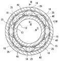
図1はこの発明の実施例1に係る玉軸受用保持器を示す斜視図である。図2は玉軸受の内輪と外輪との間に保持器が配設された状態を示す正面図である。図3は図2のIII−III線に基づく縦断面図である。図4は図2のIV−IV線に基づく縦断面図である。
[Example 1]
A first embodiment of the present invention will be described with reference to FIGS.
1 is a perspective view showing a ball bearing retainer according to Embodiment 1 of the present invention. FIG. 2 is a front view showing a state in which a cage is disposed between the inner ring and the outer ring of the ball bearing. 3 is a longitudinal sectional view based on the line III-III in FIG. 4 is a longitudinal sectional view based on the line IV-IV in FIG.
図2と図3に示すように、この実施例1に係る玉軸受用保持器(以下単に保持器という)20は、内輪12の外径面に形成された軌道面13と、外輪15の内径面に形成された軌道面16との間の環状空間に配設されて複数の玉18を転動可能に保持する。
As shown in FIGS. 2 and 3, a ball bearing cage (hereinafter simply referred to as a cage) 20 according to the first embodiment includes a
図1に示すように、保持器20は、軸方向両端部に配置された第1、第2の環状体21、22と、これら第1、第2の環状体21、22を連結すると共に複数の玉18を周方向に所定間隔を隔てて転動可能に収納する複数のポケット25を区画形成するための複数の柱体26とを備えている。
また、保持器20は、複数の柱体26において軸方向に分割され、これら分割部において結合される第1、第2の分割体30、35によって分割構成されている。
すなわち、第1、第2の分割体30、35の各柱体26の分割部分には、弾性的に係合する係合部31、36が形成され、これら係合部31、36の係合力によって第1、第2の分割体30、35が一体状に結合されることで保持器20を構成している(図4参照)。なお、弾性的に係合する係合部31、36は、例えば、特許文献1(特開2006−292097号公報)に開示された構造ものを採用してもよい。
また、第1、第2の分割体30、35は、共に耐摩耗性及び耐熱性を有する合成樹脂材の射出成形によって形成されている。
As shown in FIG. 1, the
The
That is,
The first and second divided
図1〜図3に示すように、保持器20の第1、第2の環状体21、22の外径側で各柱体26に対応する部分には潤滑油の排出溝40が凹設されている。
この実施例1において、排出溝40は、柱体26の周方向中央部に対応する部分が深く、柱体26の周方向両側に対応する部分に向かうにしたがって浅くなった凹湾曲状、凹円弧状等に形成されている。
また、図4に示すように、各柱体26の外径側部分には、ポケット25から流出された潤滑油を排出溝40に導く誘導凹部50が凹設されている。
この実施例1において、誘導凹部50は、柱体26の軸方向中央部が深く、両端の第1、第2の環状体21、22に向かうにしたがって浅くなった凹湾曲状、凹円弧状等に形成されている。
As shown in FIGS. 1 to 3, a lubricating
In the first embodiment, the
Further, as shown in FIG. 4, a guide recess 50 that guides the lubricating oil flowing out from the
In the first embodiment, the guide recess 50 has a concave curved shape, a concave arc shape, or the like in which the central portion in the axial direction of the
上述したように構成されるこの実施例1に係る玉軸受用保持器において、第1、第2の分割体30、35によって分割構成された両抱き式の保持器20とすることで、片抱き式の保持器と比べ、玉18に対する保持剛性を高くすることができ、高速回転用に適する。
また、軸受け回転時において、保持器25の内径側からポケット25内に流入した潤滑油は遠心力の作用によって外径側へ向けて流れる。
そして、潤滑油は柱体26の誘導凹部50に沿って流れた後、第1又は第2の環状体21、22の排出溝40より円滑に排出される。
前記したようにして、ポケット25内に流入した潤滑油は柱体26の誘導凹部50を経て第1又は第2の環状体21、22の排出溝40より円滑に排出されるため、潤滑油の攪拌抵抗を低減してトルク損失を良好に抑制することができる。
In the ball bearing retainer according to the first embodiment configured as described above, the double-
Further, during bearing rotation, the lubricating oil that has flowed into the
The lubricating oil flows along the guide recess 50 of the
As described above, the lubricating oil flowing into the
〔実施例2〕
この発明の実施例1を図5と図6にしたがって説明する。
図5はこの発明の実施例2に係る玉軸受用保持器を示す斜視図である。図6は玉軸受の内輪と外輪との間に保持器が配設された状態を示す縦断面図である。
図5と図6に示すように、この実施例2においても、実施例1と同様にして、軸方向両端部に配置された第1、第2の環状体121、122と、これら第1、第2の環状体121、122を連結すると共に複数の玉118を周方向に所定間隔を隔てて転動可能に収納する複数のポケット125を区画形成するための複数の柱体126とを備えている。
また、保持器120を分割構成する第1、第2の分割体130、135は、その各柱体126の分割部分に形成された係合部131、136の係合力によって一体状に結合される。
また、保持器120の第1、第2の環状体121、122の外径側で各柱体126に対応する部分には、実施例1と同様にして潤滑油の排出溝140が凹設されている。
特に、この実施例2において、保持器120の各柱体126の外径側部分は、その軸方向のほぼ全長にわたって第1、第2の環状体121、122の外径寸法よりも小さく形成され、これによって各柱体126の外径側部分に誘導凹部150が形成されている。
この実施例2のその他の構成は、実施例1と同様にして構成されるため、同一構成部分に対し同一符号を付記してその説明は省略する。
したがって、この実施例2においても実施例1と同様の作用効果を奏する。
[Example 2]
A first embodiment of the present invention will be described with reference to FIGS.
FIG. 5 is a perspective view showing a ball bearing retainer according to Embodiment 2 of the present invention. FIG. 6 is a longitudinal sectional view showing a state in which a cage is disposed between the inner ring and the outer ring of the ball bearing.
As shown in FIGS. 5 and 6, also in the second embodiment, in the same manner as in the first embodiment, the first and second
Further, the first and second divided
Also, in the portion corresponding to each
In particular, in the second embodiment, the outer diameter side portion of each
Since other configurations of the second embodiment are configured in the same manner as the first embodiment, the same components are denoted by the same reference numerals, and the description thereof is omitted.
Therefore, this second embodiment also has the same operational effects as the first embodiment.
なお、この発明は前記実施例1及び2に限定するものではなく、この発明の要旨を逸脱しない範囲内において、種々なる形態で実施することもできる。
例えば、保持器20(120)の各柱体26(126)の外径側部分に形成される誘導凹部50(150)の形状は、ポケット25(125)内に流入した潤滑油を第1又は第2の環状体21、22(121、122)の排出溝40(140)に誘導できる形状であればどのような形状であってもよい。
また、排出溝40(140)においても、潤滑油を排出できる形状であればどのような形状であってもよい。
In addition, this invention is not limited to the said Example 1 and 2, In the range which does not deviate from the summary of this invention, it can also be implemented with a various form.
For example, the shape of the guide recess 50 (150) formed in the outer diameter side portion of each pillar body 26 (126) of the cage 20 (120) is the first or the lubricating oil flowing into the pocket 25 (125). Any shape may be used as long as it can be guided to the discharge groove 40 (140) of the second
Further, the discharge groove 40 (140) may have any shape as long as the lubricant can be discharged.
12 内輪
15 外輪
18 玉
20、120 保持器
21、121 第1の環状体
22、122 第2の環状体
25、125 ポケット
26、126 柱体
30、130 第1の分割体
35、135 第2の分割体
40、140 排出溝
50、150 誘導凹部
12
Claims (1)
軸方向両端部に配置された第1、第2の環状体と、これら第1、第2の環状体を連結すると共に、前記玉を収納する複数のポケットを区画形成する複数の柱体とを備え、
前記複数の柱体において軸方向に分割され、これら各柱分割部において結合される第1、第2の両分割体によって分割構成され、
前記第1、第2の環状体の外径側で前記柱体に対応する部分には潤滑油の排出溝が凹設され、
前記柱体の外径側部分には、前記ポケットから流出された潤滑油を前記排出溝に導く誘導凹部が凹設されていることを特徴とする玉軸受用保持器。 A ball bearing retainer that is disposed in an annular space between an inner ring and an outer ring, and holds a plurality of balls in a rollable manner between the inner ring and the outer ring,
First and second annular bodies arranged at both ends in the axial direction, and a plurality of pillars that connect the first and second annular bodies and that define a plurality of pockets for housing the balls. Prepared,
The plurality of pillars are divided in the axial direction and divided by both the first and second divided parts joined at each of the pillar division parts,
A lubricating oil discharge groove is recessed in a portion corresponding to the column on the outer diameter side of the first and second annular bodies,
A ball bearing retainer characterized in that a guide recess for guiding the lubricating oil flowing out from the pocket to the discharge groove is formed in an outer diameter side portion of the column body.
Priority Applications (1)
| Application Number | Priority Date | Filing Date | Title |
|---|---|---|---|
| JP2008080603A JP2009236163A (en) | 2008-03-26 | 2008-03-26 | Retainer for ball bearing |
Applications Claiming Priority (1)
| Application Number | Priority Date | Filing Date | Title |
|---|---|---|---|
| JP2008080603A JP2009236163A (en) | 2008-03-26 | 2008-03-26 | Retainer for ball bearing |
Publications (1)
| Publication Number | Publication Date |
|---|---|
| JP2009236163A true JP2009236163A (en) | 2009-10-15 |
Family
ID=41250369
Family Applications (1)
| Application Number | Title | Priority Date | Filing Date |
|---|---|---|---|
| JP2008080603A Pending JP2009236163A (en) | 2008-03-26 | 2008-03-26 | Retainer for ball bearing |
Country Status (1)
| Country | Link |
|---|---|
| JP (1) | JP2009236163A (en) |
Cited By (7)
| Publication number | Priority date | Publication date | Assignee | Title |
|---|---|---|---|---|
| CN104141690A (en) * | 2013-05-08 | 2014-11-12 | 襄阳汽车轴承股份有限公司 | Ball bearing holder with lubricant holes and fat storage tanks |
| CN104141694A (en) * | 2013-05-08 | 2014-11-12 | 襄阳汽车轴承股份有限公司 | Deep groove ball bearing with lubrication holes and fat storage tanks in holder ball pockets |
| DE102013215204A1 (en) * | 2013-08-02 | 2015-02-05 | Schaeffler Technologies Gmbh & Co. Kg | Split rolling element cage made of plastic |
| US10451112B2 (en) * | 2015-11-25 | 2019-10-22 | Schaeffler Technologies AG & Co. KG | Ball bearing cage |
| CN110686009A (en) * | 2019-10-29 | 2020-01-14 | 瓦房店轴承集团国家轴承工程技术研究中心有限公司 | Improved single-row cylindrical roller bearing |
| CN114001094A (en) * | 2021-11-23 | 2022-02-01 | 苏州汇智精保持架科技有限公司 | Multifunctional glass fiber injection molding bearing retainer and preparation method thereof |
| CN117249170A (en) * | 2023-09-19 | 2023-12-19 | 宜兴华永电机有限公司 | Motor bearing unit with oil leakage prevention lubrication sealing structure |
-
2008
- 2008-03-26 JP JP2008080603A patent/JP2009236163A/en active Pending
Cited By (10)
| Publication number | Priority date | Publication date | Assignee | Title |
|---|---|---|---|---|
| CN104141690A (en) * | 2013-05-08 | 2014-11-12 | 襄阳汽车轴承股份有限公司 | Ball bearing holder with lubricant holes and fat storage tanks |
| CN104141694A (en) * | 2013-05-08 | 2014-11-12 | 襄阳汽车轴承股份有限公司 | Deep groove ball bearing with lubrication holes and fat storage tanks in holder ball pockets |
| DE102013215204A1 (en) * | 2013-08-02 | 2015-02-05 | Schaeffler Technologies Gmbh & Co. Kg | Split rolling element cage made of plastic |
| US10451112B2 (en) * | 2015-11-25 | 2019-10-22 | Schaeffler Technologies AG & Co. KG | Ball bearing cage |
| CN110686009A (en) * | 2019-10-29 | 2020-01-14 | 瓦房店轴承集团国家轴承工程技术研究中心有限公司 | Improved single-row cylindrical roller bearing |
| CN110686009B (en) * | 2019-10-29 | 2024-02-09 | 瓦房店轴承集团国家轴承工程技术研究中心有限公司 | Improved single-row cylindrical roller bearing |
| CN114001094A (en) * | 2021-11-23 | 2022-02-01 | 苏州汇智精保持架科技有限公司 | Multifunctional glass fiber injection molding bearing retainer and preparation method thereof |
| CN114001094B (en) * | 2021-11-23 | 2024-05-24 | 苏州汇智精保持架科技有限公司 | Multifunctional glass fiber injection molding bearing retainer and preparation method thereof |
| CN117249170A (en) * | 2023-09-19 | 2023-12-19 | 宜兴华永电机有限公司 | Motor bearing unit with oil leakage prevention lubrication sealing structure |
| CN117249170B (en) * | 2023-09-19 | 2024-04-30 | 宜兴华永电机有限公司 | Motor bearing unit with oil leakage prevention lubrication sealing structure |
Similar Documents
| Publication | Publication Date | Title |
|---|---|---|
| JP2009058039A (en) | Cage for rolling bearing | |
| JP2009236163A (en) | Retainer for ball bearing | |
| US8714832B2 (en) | Conical roller cage | |
| JP2005321049A (en) | Roller bearing | |
| JP2008051295A (en) | Tapered roller bearing and retainer | |
| JP2010174918A (en) | Conical bearing | |
| JP5343457B2 (en) | Roller bearing cage | |
| JP2016023648A (en) | Ball bearing | |
| JP2007315587A (en) | Retainer for synthetic resin-made bearing | |
| JP4946881B2 (en) | Rolling bearing | |
| JP2016180417A (en) | Conical roller bearing | |
| JP2013145012A (en) | Thrust roller bearing and thrust roller bearing apparatus | |
| JP2008014335A (en) | Tapered roller bearing | |
| JP5644350B2 (en) | Roller bearing cage and rolling bearing | |
| JP2008208973A (en) | Tapered roller bearing | |
| JP2009008170A (en) | Retainer made of resin, and ball bearing using this retainer | |
| JP2008286232A (en) | Radial needle bearing | |
| JP2008240950A (en) | Retainer for rolling bearing | |
| JP2008223891A (en) | Tapered roller bearing | |
| JP2008232420A (en) | Cage for radial ball bearing, and radial ball bearing | |
| JP2008175257A (en) | Deep groove ball bearing | |
| JP2008032153A (en) | Crown retainer | |
| JP6728675B2 (en) | Rolling bearing | |
| JP2009008274A (en) | Ball bearing | |
| JP2009024796A (en) | Rolling bearing |