JP2009234109A - Liquid jet apparatus and driving method of liquid jet head - Google Patents
Liquid jet apparatus and driving method of liquid jet head Download PDFInfo
- Publication number
- JP2009234109A JP2009234109A JP2008084658A JP2008084658A JP2009234109A JP 2009234109 A JP2009234109 A JP 2009234109A JP 2008084658 A JP2008084658 A JP 2008084658A JP 2008084658 A JP2008084658 A JP 2008084658A JP 2009234109 A JP2009234109 A JP 2009234109A
- Authority
- JP
- Japan
- Prior art keywords
- ejection
- nozzle
- pulse
- liquid
- pressure
- Prior art date
- Legal status (The legal status is an assumption and is not a legal conclusion. Google has not performed a legal analysis and makes no representation as to the accuracy of the status listed.)
- Withdrawn
Links
Images


Classifications
-
- B—PERFORMING OPERATIONS; TRANSPORTING
- B41—PRINTING; LINING MACHINES; TYPEWRITERS; STAMPS
- B41J—TYPEWRITERS; SELECTIVE PRINTING MECHANISMS, i.e. MECHANISMS PRINTING OTHERWISE THAN FROM A FORME; CORRECTION OF TYPOGRAPHICAL ERRORS
- B41J2/00—Typewriters or selective printing mechanisms characterised by the printing or marking process for which they are designed
- B41J2/005—Typewriters or selective printing mechanisms characterised by the printing or marking process for which they are designed characterised by bringing liquid or particles selectively into contact with a printing material
- B41J2/01—Ink jet
- B41J2/015—Ink jet characterised by the jet generation process
- B41J2/04—Ink jet characterised by the jet generation process generating single droplets or particles on demand
- B41J2/045—Ink jet characterised by the jet generation process generating single droplets or particles on demand by pressure, e.g. electromechanical transducers
- B41J2/04501—Control methods or devices therefor, e.g. driver circuits, control circuits
- B41J2/04596—Non-ejecting pulses
-
- B—PERFORMING OPERATIONS; TRANSPORTING
- B41—PRINTING; LINING MACHINES; TYPEWRITERS; STAMPS
- B41J—TYPEWRITERS; SELECTIVE PRINTING MECHANISMS, i.e. MECHANISMS PRINTING OTHERWISE THAN FROM A FORME; CORRECTION OF TYPOGRAPHICAL ERRORS
- B41J2/00—Typewriters or selective printing mechanisms characterised by the printing or marking process for which they are designed
- B41J2/005—Typewriters or selective printing mechanisms characterised by the printing or marking process for which they are designed characterised by bringing liquid or particles selectively into contact with a printing material
- B41J2/01—Ink jet
- B41J2/015—Ink jet characterised by the jet generation process
- B41J2/04—Ink jet characterised by the jet generation process generating single droplets or particles on demand
- B41J2/045—Ink jet characterised by the jet generation process generating single droplets or particles on demand by pressure, e.g. electromechanical transducers
- B41J2/04501—Control methods or devices therefor, e.g. driver circuits, control circuits
- B41J2/04581—Control methods or devices therefor, e.g. driver circuits, control circuits controlling heads based on piezoelectric elements
-
- B—PERFORMING OPERATIONS; TRANSPORTING
- B41—PRINTING; LINING MACHINES; TYPEWRITERS; STAMPS
- B41J—TYPEWRITERS; SELECTIVE PRINTING MECHANISMS, i.e. MECHANISMS PRINTING OTHERWISE THAN FROM A FORME; CORRECTION OF TYPOGRAPHICAL ERRORS
- B41J2/00—Typewriters or selective printing mechanisms characterised by the printing or marking process for which they are designed
- B41J2/005—Typewriters or selective printing mechanisms characterised by the printing or marking process for which they are designed characterised by bringing liquid or particles selectively into contact with a printing material
- B41J2/01—Ink jet
- B41J2/015—Ink jet characterised by the jet generation process
- B41J2/04—Ink jet characterised by the jet generation process generating single droplets or particles on demand
- B41J2/045—Ink jet characterised by the jet generation process generating single droplets or particles on demand by pressure, e.g. electromechanical transducers
- B41J2/04501—Control methods or devices therefor, e.g. driver circuits, control circuits
- B41J2/04588—Control methods or devices therefor, e.g. driver circuits, control circuits using a specific waveform
-
- B—PERFORMING OPERATIONS; TRANSPORTING
- B41—PRINTING; LINING MACHINES; TYPEWRITERS; STAMPS
- B41J—TYPEWRITERS; SELECTIVE PRINTING MECHANISMS, i.e. MECHANISMS PRINTING OTHERWISE THAN FROM A FORME; CORRECTION OF TYPOGRAPHICAL ERRORS
- B41J2/00—Typewriters or selective printing mechanisms characterised by the printing or marking process for which they are designed
- B41J2/005—Typewriters or selective printing mechanisms characterised by the printing or marking process for which they are designed characterised by bringing liquid or particles selectively into contact with a printing material
- B41J2/01—Ink jet
- B41J2/015—Ink jet characterised by the jet generation process
- B41J2/04—Ink jet characterised by the jet generation process generating single droplets or particles on demand
- B41J2/045—Ink jet characterised by the jet generation process generating single droplets or particles on demand by pressure, e.g. electromechanical transducers
- B41J2/04501—Control methods or devices therefor, e.g. driver circuits, control circuits
- B41J2/04593—Dot-size modulation by changing the size of the drop
Abstract
Description
本発明は、ノズル開口から液体を噴射する液体噴射ヘッドを具備する液体噴射装置及び液体噴射ヘッドの駆動方法に関する。 The present invention relates to a liquid ejecting apparatus including a liquid ejecting head that ejects liquid from a nozzle opening and a method for driving the liquid ejecting head.
インクジェット式プリンタやプロッタ等のインクジェット式記録装置は、インクカートリッジやインクタンク等のインク貯留手段に貯留されたインクを、インク滴として吐出可能なインクジェット式記録ヘッドを有する。 An ink jet recording apparatus such as an ink jet printer or plotter has an ink jet recording head capable of ejecting ink stored in an ink storage means such as an ink cartridge or an ink tank as ink droplets.
ここで、インクジェット式記録ヘッドとしては、ノズル開口に連通する圧力発生室と、複数の圧力発生室に連通する共通の液体室であるリザーバと、圧力発生室に圧力変化を生じさせてノズル開口から液滴を吐出させる圧力発生手段とを具備する。そして、インクジェット式記録ヘッドに搭載される圧力発生手段としては、例えば、縦振動型の圧電素子、撓み振動型の圧電素子、静電気力を用いたもの、発熱素子を用いたものなどが挙げられる。 Here, the ink jet recording head includes a pressure generating chamber that communicates with the nozzle openings, a reservoir that is a common liquid chamber that communicates with a plurality of pressure generating chambers, and a pressure change that occurs in the pressure generating chambers from the nozzle openings. Pressure generating means for discharging droplets. Examples of pressure generating means mounted on the ink jet recording head include longitudinal vibration type piezoelectric elements, flexural vibration type piezoelectric elements, those using electrostatic force, and those using heating elements.
このようなインクジェット式記録ヘッドでは、あるノズル開口からインクを吐出した際に、圧力発生手段の動作による圧力発生室のインクの圧力変動に伴い、圧力発生室を画成する隔壁が隣の圧力発生室側に撓み変形して、圧力損失が発生し、インクの飛翔速度の低下や、インク吐出量の減少等の吐出特性が変化する虞がある。また、このような圧力損失は、圧力発生室を画成する隔壁の変形によるものだけではなく、圧力発生室とリザーバとの間でも発生する。 In such an ink jet recording head, when ink is ejected from a certain nozzle opening, the partition that defines the pressure generation chamber generates pressure next to the pressure variation of the ink in the pressure generation chamber due to the operation of the pressure generation means. There is a possibility that pressure deformation occurs due to bending deformation to the chamber side, and ejection characteristics such as a decrease in the flying speed of the ink and a decrease in the ink ejection amount may change. Further, such a pressure loss occurs not only due to the deformation of the partition wall defining the pressure generation chamber, but also between the pressure generation chamber and the reservoir.
このため、インクを吐出する吐出ノズルの吐出タイミングに合わせて、吐出ノズルの隣に位置する休止ノズルに対応する圧力発生手段にインクを吐出しない程度の駆動を行わせるようにした液体噴射装置が提案されている(例えば、特許文献1参照)。 For this reason, a liquid ejecting apparatus is proposed in which the pressure generating means corresponding to the idle nozzle located next to the ejection nozzle is driven to the extent that the ink is not ejected in accordance with the ejection timing of the ejection nozzle that ejects the ink. (For example, refer to Patent Document 1).
しかしながら、特許文献1では、インクを吐出する吐出ノズル以外の全ての休止ノズルにインクを吐出しない程度の駆動を行わせると消費電力が増大してしまうという問題がある。 However, in Patent Document 1, there is a problem in that power consumption increases if all the idle nozzles other than the ejection nozzles that eject ink are driven to the extent that ink is not ejected.
なお、このような問題はインクジェット式記録装置だけではなく、インク以外の液体を噴射する液体噴射装置においても同様に存在する。 Such a problem exists not only in the ink jet recording apparatus but also in a liquid ejecting apparatus that ejects liquid other than ink.
本発明はこのような事情に鑑み、液体を吐出するノズル開口の数に拘わらず、液体吐出特性を常に一定に揃えることができると共に消費電力を低減した液体噴射装置及び液体噴射ヘッドの駆動方法を提供することを目的とする。 In view of such circumstances, the present invention provides a liquid ejecting apparatus and a liquid ejecting head driving method that can always maintain uniform liquid ejecting characteristics and reduce power consumption regardless of the number of nozzle openings that eject liquid. The purpose is to provide.
上記課題を解決する本発明の態様は、液体を吐出するノズル開口に連通する圧力発生室と、該圧力発生室に圧力変化を生じさせる圧力発生手段とを具備する液体噴射ヘッドを具備し、前記ノズル開口から液体を吐出する吐出ノズルからの液体の吐出タイミングに合わせて、前記吐出ノズルの周辺の当該吐出ノズルの隣に位置する少なくとも1つを含む休止ノズルを選択して、当該選択した休止ノズルに対応する前記圧力発生手段を駆動して、前記休止ノズルに連通する前記圧力発生室を液体が吐出されない程度に加圧する非吐出駆動を行わせると共に、非選択の休止ノズルに対応する前記圧力発生手段に前記非吐出駆動を行わせないようにしたことを特徴とする液体噴射装置にある。 An aspect of the present invention that solves the above-described problem includes a liquid ejecting head that includes a pressure generating chamber that communicates with a nozzle opening that discharges liquid, and a pressure generating unit that causes a pressure change in the pressure generating chamber. In accordance with the discharge timing of the liquid from the discharge nozzle that discharges the liquid from the nozzle opening, a pause nozzle including at least one located next to the discharge nozzle around the discharge nozzle is selected, and the selected pause nozzle Driving the pressure generating means corresponding to the non-discharge nozzle to pressurize the pressure generation chamber communicating with the idle nozzle to such an extent that no liquid is discharged, and generating the pressure corresponding to the non-selected idle nozzle The liquid ejecting apparatus is characterized in that the non-ejection driving is not performed by the means.
かかる態様では、吐出ノズルの液滴の吐出タイミングに合わせて、吐出ノズルの隣に位置する少なくとも1つの休止ノズルに対応する圧力発生手段に非吐出駆動を行わせることによって、圧力損失を低減することができる。これにより液滴を吐出するノズル開口の数や位置に拘わらず、液滴の飛翔速度の低下や液滴量の減少等の吐出特性のばらつきを抑制して吐出特性を均一化することができる。また、全ての休止ノズルを非吐出駆動させないようにすることで、消費電力を減少させることができる。 In such an aspect, the pressure loss is reduced by causing the pressure generating means corresponding to at least one idle nozzle located next to the discharge nozzle to perform non-discharge driving in accordance with the discharge timing of the droplets of the discharge nozzle. Can do. Thereby, regardless of the number and position of the nozzle openings for discharging the droplets, it is possible to make the discharge characteristics uniform by suppressing variations in the discharge characteristics such as a decrease in the flying speed of the droplets and a decrease in the droplet amount. Further, power consumption can be reduced by preventing all the idle nozzles from being non-ejection driven.
ここで、前記吐出ノズルの両側のそれぞれ10本の前記休止ノズルに対応する前記圧力発生手段を非吐出駆動させることが好ましい。これによれば、液滴の吐出特性のばらつきを確実に抑制することができると共に消費電力を減少させることができる。 Here, it is preferable that the pressure generating units corresponding to the ten pause nozzles on both sides of the discharge nozzle are non-discharge driven. According to this, it is possible to surely suppress variations in droplet discharge characteristics and to reduce power consumption.
また、複数の駆動信号を吐出周期毎に同時に繰り返し発生可能な駆動信号発生手段と、該駆動信号発生手段から発生する駆動信号に含まれるパルスを選択して、前記圧力発生手段に供給する選択供給手段とを具備し、前記駆動信号発生手段は、前記圧力発生室の液体に前記ノズル開口から液体を吐出させない程度に圧力変動を生じさせる非吐出パルスを含む非吐出駆動信号を発生し、前記非吐出駆動信号は、他の駆動信号に含まれる吐出パルスに対応させて前記非吐出パルスが配置され、前記選択供給手段は、前記吐出ノズルに対応する前記圧力発生手段への吐出パルスの供給タイミングに合わせて、選択した前記休止ノズルに対応する前記圧力発生手段に非吐出パルスを供給することが好ましい。これによれば、吐出ノズルに対応する圧力発生手段への吐出パルスの供給タイミングに合わせて、休止ノズルに対応する圧力発生手段に非吐出パルスの供給・非供給を選択的に実行させることができる。 Further, a drive signal generating means capable of repeatedly generating a plurality of drive signals simultaneously for each ejection cycle, and a selective supply for selecting a pulse included in the drive signal generated from the drive signal generating means and supplying it to the pressure generating means And the drive signal generating means generates a non-ejection drive signal including a non-ejection pulse that causes a pressure fluctuation to the extent that the liquid in the pressure generation chamber is not ejected from the nozzle opening. The non-ejection pulse is arranged corresponding to the ejection pulse included in the other driving signal as the ejection drive signal, and the selection supply unit is configured to supply the ejection pulse to the pressure generation unit corresponding to the ejection nozzle. In addition, it is preferable to supply a non-ejection pulse to the pressure generating means corresponding to the selected idle nozzle. According to this, it is possible to selectively execute supply / non-supply of the non-ejection pulse to the pressure generation means corresponding to the idle nozzle in accordance with the supply timing of the ejection pulse to the pressure generation means corresponding to the ejection nozzle. .
また、前記駆動信号発生手段は、種類の異なる吐出パルスを発生すると共に、各吐出パルスの発生期間に対応させて前記非吐出パルスをそれぞれ配置することも可能である。 Further, the drive signal generating means can generate different types of ejection pulses and can arrange the non-ejection pulses in correspondence with the generation periods of the ejection pulses.
また、前記非吐出パルスによる前記圧力発生室の収縮要素のタイミングを、対応する前記吐出パルスの前記圧力発生室の収縮要素のタイミングに揃えることが好ましい。これによれば、吐出ノズルと非吐出駆動を行わせる休止ノズルとで圧力発生室の液体の加圧が同時に行われるので、吐出ノズルの圧力発生室から休止ノズルの圧力発生室への圧力損失を確実に低減させることができる。 Further, it is preferable that the timing of the contraction element of the pressure generation chamber by the non-ejection pulse is aligned with the timing of the contraction element of the pressure generation chamber of the corresponding ejection pulse. According to this, since the pressurization of the liquid in the pressure generation chamber is simultaneously performed by the discharge nozzle and the pause nozzle that performs non-discharge driving, the pressure loss from the pressure generation chamber of the discharge nozzle to the pressure generation chamber of the pause nozzle is reduced. It can be reliably reduced.
また、前記非吐出パルスは、液体が吐出されない程度に前記ノズル開口に露出した液体の表面を微振動させる微振動パルスであることが好ましい。これによれば、非吐出パルスとして既存の微振動パルスを利用することで、複数の駆動信号を用いて吐出制御が可能な従来の液体噴射装置に対して簡単な設計変更を施すだけで、クロストークを防止可能な構成を実現できる。 The non-ejection pulse is preferably a micro-vibration pulse that micro-vibrates the surface of the liquid exposed to the nozzle opening to such an extent that no liquid is ejected. According to this, by using an existing micro-vibration pulse as a non-ejection pulse, a simple design change can be made to a conventional liquid ejecting apparatus capable of ejecting control using a plurality of drive signals. A configuration capable of preventing talk can be realized.
また、前記非吐出パルスは、対応する前記吐出パルスの駆動電圧を液体が吐出されない程度に低下させたカウンターパルスであることが好ましい。これによれば、吐出パルスと非吐出パルスとで、圧力発生室の液体に圧力変動を与えるタイミングを合致させることができ、圧力損失をより効果的に抑制することができる。 Further, it is preferable that the non-ejection pulse is a counter pulse in which the driving voltage of the corresponding ejection pulse is reduced to such an extent that no liquid is ejected. According to this, the timing at which the pressure fluctuation is applied to the liquid in the pressure generating chamber can be matched between the ejection pulse and the non-ejection pulse, and the pressure loss can be more effectively suppressed.
さらに、本発明の他の態様は、液体を吐出するノズル開口に連通する圧力発生室と、該圧力発生室に圧力変化を生じさせる圧力発生手段とを具備する液体噴射ヘッドの駆動方法であって、前記ノズル開口から液体を吐出する吐出ノズルからの液体の吐出タイミングに合わせて、前記吐出ノズルの周辺の当該吐出ノズルの隣に位置する少なくとも1つを含む休止ノズルを選択して、当該選択した休止ノズルに対応する前記圧力発生手段を駆動して、前記休止ノズルに連通する前記圧力発生室を液体が吐出されない程度に加圧する非吐出駆動を行わせると共に、非選択の休止ノズルに対応する前記圧力発生手段に前記非吐出駆動を行わせないようにしたことを特徴とする液体噴射ヘッドの駆動方法にある。 According to another aspect of the present invention, there is provided a method for driving a liquid ejecting head, comprising: a pressure generating chamber that communicates with a nozzle opening that discharges liquid; and a pressure generating unit that causes a pressure change in the pressure generating chamber. In accordance with the liquid discharge timing from the discharge nozzle that discharges the liquid from the nozzle opening, the idle nozzle including at least one located next to the discharge nozzle around the discharge nozzle is selected and selected. The pressure generating means corresponding to the pause nozzle is driven to perform non-ejection drive that pressurizes the pressure generation chamber communicating with the pause nozzle to such an extent that liquid is not ejected, and the pressure generation chamber corresponding to the non-selected pause nozzle The liquid ejecting head driving method is characterized in that the non-ejection driving is not performed by the pressure generating means.
かかる態様では、吐出ノズルの液滴の吐出タイミングに合わせて、吐出ノズルの隣に位置する休止ノズルに対応する圧力発生手段に非吐出駆動を行わせることによって、圧力損失を低減することができる。これにより液滴を吐出するノズル開口の数や位置に拘わらず、液滴の飛翔速度の低下や液滴量の減少等の吐出特性のばらつきを抑制して吐出特性を均一化することができる。また、全ての休止ノズルを非吐出駆動させないようにすることで、消費電力を減少させることができる。 In such an aspect, the pressure loss can be reduced by causing the pressure generating means corresponding to the idle nozzle located next to the discharge nozzle to perform non-discharge driving in accordance with the discharge timing of the droplets of the discharge nozzle. Thereby, regardless of the number and position of the nozzle openings for discharging the droplets, it is possible to make the discharge characteristics uniform by suppressing variations in the discharge characteristics such as a decrease in the flying speed of the droplets and a decrease in the droplet amount. Further, power consumption can be reduced by preventing all the idle nozzles from being non-ejection driven.
以下に本発明を実施形態に基づいて詳細に説明する。
(実施形態1)
図1は、本発明の一実施形態に係る液体噴射装置の一例であるインクジェット式記録装置の概略斜視図である。
Hereinafter, the present invention will be described in detail based on embodiments.
(Embodiment 1)
FIG. 1 is a schematic perspective view of an ink jet recording apparatus which is an example of a liquid ejecting apparatus according to an embodiment of the invention.
本実施形態の液体噴射装置は、例えば、インクジェット式記録装置であり、図1に示すように、詳しくは後述するインクジェット式記録ヘッドを有する記録ヘッドユニット1A及び1Bは、インク供給手段を構成するインクカートリッジ2A及び2Bが着脱可能に設けられ、この記録ヘッドユニット1A及び1Bを搭載したキャリッジ3は、装置本体4に取り付けられたキャリッジ軸5に軸方向移動自在に設けられている。この記録ヘッドユニット1A及び1Bは、それぞれブラックインク組成物及びカラーインク組成物を吐出するものとしている。
The liquid ejecting apparatus according to the present embodiment is, for example, an ink jet recording apparatus. As shown in FIG. 1, recording
また、キャリッジ軸5の一端部近傍には、駆動モータ6が設けられており、駆動モータ6の軸の先端部には外周に溝を有する第1のプーリ6aが設けられている。さらに、キャリッジ軸5の他端部近傍には、駆動モータ6の第1のプーリ6aに対応する第2のプーリ6bが回転自在に設けられており、これら第1のプーリ6aと第2のプーリ6bとの間には環状でゴム等の弾性部材からなるタイミングベルト7が掛けられている。
A drive motor 6 is provided in the vicinity of one end of the
そして、駆動モータ6の駆動力がタイミングベルト7を介してキャリッジ3に伝達されることで、記録ヘッドユニット1A及び1Bを搭載したキャリッジ3はキャリッジ軸5に沿って移動される。一方、装置本体4にはキャリッジ3に沿ってプラテン8が設けられている。このプラテン8は図示しない紙送りモータの駆動力により回転できるようになっており、給紙ローラなどにより給紙された紙等の記録媒体である記録シートSがプラテン8に巻き掛けられて搬送されるようになっている。
Then, the driving force of the driving motor 6 is transmitted to the carriage 3 via the timing belt 7, so that the carriage 3 on which the
ここで、上述のようなインクジェット式記録装置Iに搭載されるインクジェット式記録ヘッドについて説明する。図2は、本発明の実施形態1に係るインクジェット式記録ヘッドの一例を示す断面図である。 Here, an ink jet recording head mounted on the ink jet recording apparatus I as described above will be described. FIG. 2 is a cross-sectional view showing an example of an ink jet recording head according to Embodiment 1 of the present invention.
図2に示すインクジェット式記録ヘッド10は、縦振動型の圧電素子を有するタイプであり、流路基板11には、複数の圧力発生室12が並設され、流路基板11の両側は、各圧力発生室12に対応してノズル開口13を有するノズルプレート14と、振動板15とにより封止されている。また、流路基板11には、各圧力発生室12毎にそれぞれインク供給口16を介して連通されて複数の圧力発生室12の共通のインク室となるリザーバ17が形成されており、リザーバ17には、図示しないインクカートリッジが接続される。
An ink
一方、振動板15の圧力発生室12とは反対側には、各圧力発生室12に対応する領域にそれぞれ圧電素子18の先端が当接されて設けられている。これらの圧電素子18は、圧電材料19と、電極形成材料20及び21とを縦に交互にサンドイッチ状に挟んで積層され、振動に寄与しない不活性領域が固定基板22に固着されている。なお、固定基板22と、振動板15、流路基板11及びノズルプレート14とは、基台23を介して一体的に固定されている。
On the other hand, on the side opposite to the
このように構成されたインクジェット式記録ヘッド10では、インクカートリッジに連通されるインク流路を介してリザーバ17にインクが供給され、インク供給口16を介して各圧力発生室12に分配される。実際には、圧電素子18に電圧を印加することにより圧電素子18を収縮させる。これにより、振動板15が圧電素子18と共に変形されて(図中上方向に引き上げられて)圧力発生室12の容積が広げられ、圧力発生室12内にインクが引き込まれる。そして、ノズル開口13に至るまで内部をインクで満たした後、駆動回路からの記録信号に従い、圧電素子18の電極形成材料20及び21に印加していた電圧を解除すると、圧電素子18が伸張されて元の状態に戻る。これにより、振動板15も変位して元の状態に戻るため圧力発生室12が収縮され、内部圧力が高まりノズル開口13からインク滴が吐出される。すなわち、本実施形態では、圧力発生室12に圧力変化を生じさせる圧力発生手段として縦振動型の圧電素子18が設けられている。
In the ink
図3は、インクジェット式記録装置の制御構成を示すブロック図である。ここで、図3を参照して、本実施形態のインクジェット式記録装置Iの制御について説明する。本実施形態のインクジェット式記録装置Iは、図3に示すように、プリンタコントローラ111とプリントエンジン112とから概略構成されている。プリンタコントローラ111は、外部インターフェース113(以下、外部I/F113という)と、各種データを一時的に記憶するRAM114と、制御プログラム等を記憶したROM115と、CPU等を含んで構成した制御部116と、クロック信号を発生する発振回路117と、インクジェット式記録ヘッド10へ供給するための駆動信号を発生する駆動信号発生回路119と、駆動信号や印刷データに基づいて展開されたドットパターンデータ(ビットマップデータ)等をプリントエンジン112に送信する内部インターフェース120(以下、内部I/F120という)とを備えている。
FIG. 3 is a block diagram showing a control configuration of the ink jet recording apparatus. Here, with reference to FIG. 3, the control of the ink jet recording apparatus I of the present embodiment will be described. As shown in FIG. 3, the ink jet recording apparatus I according to the present embodiment is schematically configured by a
外部I/F113は、例えば、キャラクタコード、グラフィック関数、イメージデータ等によって構成される印刷データを、図示しないホストコンピュータ等から受信する。また、この外部I/F113を通じてビジー信号(BUSY)やアクノレッジ信号(ACK)が、ホストコンピュータ等に対して出力される。RAM114は、受信バッファ121、中間バッファ122、出力バッファ123、及び、図示しないワークメモリとして機能する。そして、受信バッファ121は外部I/F113によって受信された印刷データを一時的に記憶し、中間バッファ122は制御部116が変換した中間コードデータを記憶し、出力バッファ123はドットパターンデータを記憶する。なお、このドットパターンデータは、階調データをデコード(翻訳)することにより得られる印字データによって構成してある。
The external I /
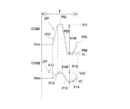
駆動信号発生回路119は、本発明の駆動信号発生手段に相当し、第1駆動信号COM1を発生可能な第1駆動信号発生部119A(第1駆動信号発生手段)と、第2駆動信号COM2を発生可能な第2駆動信号発生部119B(第2駆動信号発生手段)とを具備する。そして、図4に示すように、第1駆動信号COM1は、インクを吐出させるように圧電素子18を駆動(吐出駆動)する吐出パルスDPを1記録周期T内に有する信号であり、記録周期T毎に繰り返し発生される。
The drive
一方、第2駆動信号COM2は、吐出パルスDPに対応させて、インクを吐出しない程度に圧電素子18を駆動(非吐出駆動)する非吐出パルスであるカウンターパルスCPを1記録周期T内に有する信号であり、第1駆動信号COM1と同様に、記録周期T毎に繰り返し発生される。なお、記録周期Tは、駆動信号COMの繰り返し単位であり、本発明における吐出周期の一種である。また、これらの駆動信号COM1、COM2の詳細については後述する。
On the other hand, the second drive signal COM2 has a counter pulse CP, which is a non-ejection pulse for driving (non-ejection driving) the
また、ROM115には、各種データ処理を行わせるための制御プログラム(制御ルーチン)の他に、フォントデータ、グラフィック関数等を記憶させてある。制御部116は、受信バッファ121内の印刷データを読み出すと共に、この印刷データを変換して得た中間コードデータを中間バッファ122に記憶させる。また、中間バッファ122から読み出した中間コードデータを解析し、ROM115に記憶させているフォントデータ及びグラフィック関数等を参照して、中間コードデータをドットパターンデータに展開する。そして、制御部116は、必要な装飾処理を施した後に、この展開したドットパターンデータを出力バッファ123に記憶させる。
The
そして、液体噴射ヘッド118の1行分に相当するドットパターンデータが得られたならば、この1行分のドットパターンデータは、内部I/F120を通じて液体噴射ヘッド118に出力される。また、出力バッファ123から1行分のドットパターンデータが出力されると、展開済みの中間コードデータは中間バッファ122から消去され、次の中間コードデータについての展開処理が行われる。
If dot pattern data corresponding to one line of the liquid ejecting head 118 is obtained, the dot pattern data for one line is output to the liquid ejecting head 118 through the internal I /
プリントエンジン112は、インクジェット式記録ヘッド10と、紙送り機構124と、キャリッジ機構125とを含んで構成してある。紙送り機構124は、紙送りモータとプラテン8等から構成してあり、記録紙等の記録シートSをインクジェット式記録ヘッド10の記録動作に連動させて順次送り出す。即ち、この紙送り機構124は、記録シートSを副走査方向に相対移動させる。
The print engine 112 includes the ink
キャリッジ機構125は、インクジェット式記録ヘッド10を搭載可能なキャリッジ3と、このキャリッジ3を主走査方向に沿って走行させるキャリッジ駆動部とから構成してあり、キャリッジ3を走行させることによりインクジェット式記録ヘッド10を主走査方向に移動させる。なお、キャリッジ駆動部は、上述したように駆動モータ6及びタイミングベルト7等で構成されている。
The carriage mechanism 125 includes a carriage 3 on which the ink
インクジェット式記録ヘッド10は、副走査方向に沿って多数のノズル開口13を有し、ドットパターンデータ等によって規定されるタイミングで各ノズル開口13から液滴を吐出する。そして、このようなインクジェット式記録ヘッド10の圧電素子18には、図示しない外部配線を介して電気信号、例えば、駆動信号(COM1、COM2)や印字データ(SI)等が供給される。
The ink
ここで、本実施形態のインクジェット式記録ヘッド10の電気的構成について説明する。図3に示すように、インクジェット式記録ヘッド10は、第1シフトレジスタ131A及び第2シフトレジスタ131Bからなるシフトレジスタ回路と、第1ラッチ回路132A及び第2ラッチ回路132Bからなるラッチ回路と、デコーダ133と、制御ロジック134と、第1レベルシフタ135A及び第2レベルシフタ135Bからなるレベルシフタ回路と、第1スイッチ136A及び第2スイッチ136Bからなるスイッチ回路と、圧電素子18とを具備する。そして、各シフトレジスタ131A、131B、各ラッチ回路132A、132B、各レベルシフタ135A、135B、スイッチ136A、136B及び圧電素子18は、それぞれノズル開口13に対応して設けられている。
Here, the electrical configuration of the ink
このインクジェット式記録ヘッド10は、プリンタコントローラ111からの記録データに基づいてインク滴を吐出させる。本実施形態では、記録データの上位ビット群、記録データの下位ビット群の順にインクジェット式記録ヘッド10へ送られてくるので、まず、記録データの上位ビット群が第2シフトレジスタ131Bにセットされる。全てのノズル開口13について記録データの上位ビット群が第2シフトレジスタ131Bにセットされると、これらの上位ビット群が第1シフトレジスタ131Aにシフトする。これと同時に、記録データの下位ビット群が第2シフトレジスタ131Bにセットされる。
The ink
第1シフトレジスタ131Aの後段には、第1ラッチ回路132Aが電気的に接続され、第2シフトレジスタ131Bの後段には第2ラッチ回路132Bが電気的に接続されている。そして、プリンタコントローラ111からのラッチ信号(LAT)が各ラッチ回路132A、132Bに入力されると、第1ラッチ回路132Aは記録データの上位ビット群をラッチし、第2ラッチ回路132Bは記録データの下位ビット群をラッチする。各ラッチ回路132A、132Bでラッチされた記録データ(上位ビット群、下位ビット群)は、それぞれデコーダ133に出力される。このデコーダ133は、記録データの上位ビット群及び下位ビット群に基づいて、駆動信号COM1、COM2を構成する各パルスを選択するためのパルス選択データを生成する。
The
パルス選択データは、各駆動信号COM1、COM2毎に生成される。すなわち、第1駆動信号COM1に対応する第1パルス選択データは、1ビットのデータによって構成されている。また、第2駆動信号COM2に対応する第2パルス選択データは、1ビットのデータによって構成されている。 The pulse selection data is generated for each drive signal COM1, COM2. That is, the first pulse selection data corresponding to the first drive signal COM1 is composed of 1-bit data. The second pulse selection data corresponding to the second drive signal COM2 is composed of 1-bit data.
また、デコーダ133には、制御ロジック134からのタイミング信号も入力される。この制御ロジック134は、ラッチ信号やチャンネル信号の入力に同期してタイミング信号を発生する。このタイミング信号も駆動信号COM1、COM2毎に生成される。デコーダ133によって生成された各パルス選択データは、タイミング信号によって規定されるタイミングで上位ビット側から順次各レベルシフタ135A、135Bに入力される。これらレベルシフタ135A、135Bは、電圧増幅器として機能し、パルス選択データが「1」の場合には、対応するスイッチ136A、136Bが駆動可能な電圧値、例えば、数十ボルトに昇圧した電気信号を出力する。すなわち、第1パルス選択データが「1」の場合には、第1スイッチ136Aに電気信号が出力され、第2パルス選択データが「1」の場合には、第2スイッチ136Bに電気信号が出力されて接続状態となる。
The
第1スイッチ136Aの入力側には第1駆動信号発生部119Aからの第1駆動信号COM1が供給されており、第2スイッチ136Bの入力側には第2駆動信号発生部119Bからの第2駆動信号COM2が供給されている。また、各スイッチ136A、136Bの出力側には、圧電素子18が電気的に接続されている。そして、これら第1スイッチ136A及び第2スイッチ136Bは、発生される駆動信号の種類毎に設けられており、駆動信号発生回路119と圧電素子18との間に介在して各駆動信号COM1、COM2を圧電素子18に選択的に供給する。このような第1スイッチ136A及び第2スイッチ136Bは、本実施形態では、選択供給手段の一種として機能する。なお、第1スイッチ136A及び第2スイッチ136Bが共に切断状態となると、圧電素子18には駆動信号COM1、COM2が供給されない。したがって、選択供給手段は、圧電素子18に駆動信号COM1、COM2を選択的に供給すると共に、圧電素子18に駆動信号COM1、COM2を供給しないものである。
The first drive signal COM1 from the first
このようなパルス選択データは、各スイッチ136A、136Bの動作を制御する。すなわち、第1スイッチ136Aに入力されたパルス選択データが「1」である期間中は、この第1スイッチ136Aが接続された導通状態となり、第1駆動信号COM1が圧電素子18に供給される。同様に、第2スイッチ136Bに入力されたパルス選択データが「1」である期間中は、この第2スイッチ136Bが接続された導通状態となり、第2駆動信号COM2が圧電素子18に供給される。そして、供給された駆動信号COM1、COM2に応じて圧電素子18に印加される電圧が変化する。一方、各スイッチ136A、136Bに入力されたパルス選択データが共に「0」の期間中は、各スイッチ136A、136Bが切断状態となり、圧電素子18には駆動信号COM1、COM2が供給されない。要するにパルス選択データとして「1」が設定された期間のパルスが選択的に圧電素子18に供給される。なお、パルス選択データが共に「0」の期間において、各圧電素子18は直前の電位を保持するので、直前の変位状態が維持される。
Such pulse selection data controls the operation of each
このように、本実施形態では、デコーダ133、制御ロジック134、各レベルシフタ135A、135B及び各スイッチ136A、136Bは、圧力発生手段制御手段として機能し、記録データ(階調データ)に応じて駆動信号COM1、COM2の供給を制御することにより圧電素子18の挙動を制御する。
As described above, in the present embodiment, the
次に、駆動信号発生回路119が発生する各駆動信号COM1、COM2と、これらの駆動信号COM1、COM2の圧電素子18への供給制御について説明する。
Next, the drive signals COM1 and COM2 generated by the drive
図4に示した駆動信号は、上述したように、第1駆動信号COM1と、第2駆動信号COM2とからなる。 As described above, the drive signal illustrated in FIG. 4 includes the first drive signal COM1 and the second drive signal COM2.
第1駆動信号COM1は、1記録周期Tで発生する吐出パルスDPを具備する。吐出パルスDPは、中間電位Vhmを維持した状態から第1膨張電位Vh1まで上昇させて圧力発生室12を膨張させる第1膨張要素P01と、第1膨張電位Vh1を一定時間維持する第1ホールド要素P02と、第1膨張電位Vh1から第1収縮電位VLまで急勾配で降下させて圧力発生室12を収縮させる第1収縮要素P03と、第1収縮電位VLを一定時間維持する第2ホールド要素P04と、第1収縮電位VLから中間電位Vhmまでインク滴を吐出させない程度の一定勾配で電位を復帰させる第1制振要素P05とで構成されている。
The first drive signal COM1 includes an ejection pulse DP generated at one recording cycle T. The ejection pulse DP includes a first expansion element P01 that expands the
そして、このような第1駆動信号COM1が圧電素子18に供給されると、第1膨張要素P01によって圧電素子18が圧力発生室12の容積を膨張させる方向に変形して、ノズル開口13内のメニスカスが圧力発生室12側に引き込まれると共に、圧力発生室12にはリザーバ17側からインクが供給される。そして、圧力発生室12の膨張状態は、第1ホールド要素P02で維持される。その後、第1収縮要素P03が供給されて圧電素子18が伸長する。これにより、圧力発生室12は膨張容積から第1収縮電位VLに対応する収縮容積まで急激に収縮され、圧力発生室12内のインクが加圧されてノズル開口13からインク滴が吐出される。圧力発生室12の収縮状態は、第2ホールド要素P04で維持され、この間にインク滴の吐出によって減少した圧力発生室12内のインク圧力は、その固有振動によって再び上昇する。この上昇タイミングに合わせて第1制振要素P05が供給されて、圧力発生室12が基準容積まで復帰し、圧力発生室12内の圧力変動が吸収される。すなわち、本実施形態の駆動信号COM1で発生する吐出パルスDPは、プル−プッシュ方式のものである。
When such a first drive signal COM1 is supplied to the
第2駆動信号COM2は、非吐出駆動信号として機能し、1記録周期Tで発生する非吐出パルスであるカウンターパルスCPを具備する。ここで、カウンターパルスとは、対応する吐出パルスDPの駆動電圧(最低電位から最高電位までの電位差)をノズル開口13からインクが吐出されない程度の電圧まで低下させたパルスのことであり、対応する吐出パルスDPをそのまま縦方向(電圧変化軸方向)に縮小した形状を呈している。
The second drive signal COM2 functions as a non-ejection drive signal, and includes a counter pulse CP that is a non-ejection pulse generated in one recording cycle T. Here, the counter pulse is a pulse obtained by reducing the driving voltage (potential difference from the lowest potential to the highest potential) of the corresponding ejection pulse DP to a voltage at which ink is not ejected from the
具体的には、カウンターパルスCPは、中間電位Vhmから第2膨張電位Vh2まで上昇させて圧力発生室12を膨張させる第2膨張要素P11と、第2膨張電位Vh2を維持する第3ホールド要素P12と、第2膨張電位Vh2から第2収縮電位VL′まで下降させて圧力発生室を収縮させる第2収縮要素P13と、第2収縮電位VL′を一定時間維持する第4ホールド要素P14と、第2収縮電位VL′から中間電位Vhmまで電位を復帰させる第2制振要素P15とで構成されている。
Specifically, the counter pulse CP is increased from the intermediate potential Vhm to the second expansion potential Vh2 to expand the
このようなカウンターパルスCPでは、インクが吐出されないように各電位Vh2、VL′が設定されている。また、カウンターパルスCPの各波形要素P11〜P15の発生期間は、図4に示すように、吐出パルスDPの波形要素P01〜P05とそれぞれ一致している。そして、カウンターパルスCPの駆動電圧VhM′は、吐出パルスDPの駆動電圧VhMの10〜50%に設定されている。このため、波形要素P11、P13、P15の傾きは、それぞれ対応する波形要素P01、P03、P05の傾きよりも緩やかになっている。 With such a counter pulse CP, the potentials Vh2 and VL ′ are set so that ink is not ejected. Further, the generation periods of the waveform elements P11 to P15 of the counter pulse CP coincide with the waveform elements P01 to P05 of the ejection pulse DP, respectively, as shown in FIG. The drive voltage VhM ′ of the counter pulse CP is set to 10 to 50% of the drive voltage VhM of the ejection pulse DP. For this reason, the inclinations of the waveform elements P11, P13, and P15 are gentler than the inclinations of the corresponding waveform elements P01, P03, and P05, respectively.
ここで、第1駆動信号COM1により圧電素子18をインク滴が吐出される程度に駆動する吐出駆動と、第2駆動信号COM2により圧電素子18をインク滴が吐出されない程度に駆動する非吐出駆動と、圧電素子18に第1駆動信号COM1及び第2駆動信号COM2を供給せずに圧電素子18に圧力変動を行わせない非駆動との場合について説明する。
Here, ejection driving that drives the
まず、非駆動の場合について説明する。非駆動の場合には、デコーダ133は非駆動の階調データ「00」の翻訳により第1波形選択データ「0」、第2波形選択データ「0」を生成する。そして、圧力発生手段制御手段は、この波形選択データに基づいて第1スイッチ136A及び第2スイッチ136Bの動作を制御する。すなわち、圧力発生手段制御手段は、第1スイッチ136A及び第2スイッチ136Bの両方が切断状態となるように制御する。これにより、記録周期Tでは、第1駆動信号COM1の吐出パルスDP及び第2駆動信号COM2のカウンターパルスCPが圧電素子18に供給されず、圧電素子18は中間電位Vhmが印加された状態が維持される。
First, the case of non-driving will be described. In the case of non-driving, the
次に、吐出駆動の場合について説明する。吐出駆動の場合は、デコーダ133は、吐出駆動の階調データ「10」の翻訳により、第1波形選択データ「1」及び第2波形選択データ「0」を生成する。そして、圧力発生手段制御手段は、生成された波形選択データに基づいて第1駆動信号COM1及び第2駆動信号COM2の圧電素子18への供給を制御する。すなわち、記録周期Tで、第1スイッチ136Aが接続状態、第2スイッチ136Bが切断状態に制御される。これにより、圧電素子18には、第1駆動信号COM1の吐出パルスDPが供給され、インク滴がノズル開口13から吐出される。
Next, the case of ejection driving will be described. In the case of ejection driving, the
次に、非吐出駆動の場合について説明する。非吐出駆動の場合は、デコーダ133は、非吐出駆動の階調データ「01」の翻訳により、第1波形選択データ「0」及び第2波形選択データ「1」を生成する。そして、圧力発生手段制御手段は、生成された波形選択データに基づいて第1駆動信号COM1及び第2駆動信号COM2の圧電素子18への供給を制御する。すなわち、記録周期Tで、第1スイッチ136Aが切断状態、第2スイッチ136Bが接続状態に制御される。これにより、圧電素子18には、第2駆動信号COM2のカウンターパルスCPが供給され、圧電素子18はインク滴が吐出されない程度に圧力発生室12内のインクに圧力変動を生じさせる。
Next, the case of non-ejection driving will be described. In the case of non-ejection driving, the
そして、これらの圧電素子18の吐出駆動、非吐出駆動及び非駆動は、インク滴を吐出する吐出ノズルと、吐出ノズルの周辺の当該吐出ノズルの隣に位置する少なくとも1つを含む休止ノズルと、その他の休止ノズルとに適宜選択的に行われる。
The discharge drive, non-discharge drive, and non-drive of these
具体的には、インク滴を吐出する吐出ノズルに対応する圧電素子18には、第1駆動信号COM1の吐出パルスDPが供給されて、圧電素子18は吐出駆動を行う。
Specifically, the ejection pulse DP of the first drive signal COM1 is supplied to the
また、吐出ノズルの周辺の隣に位置する少なくとも1つを含む休止ノズルに対応する圧電素子18には、吐出ノズルに対応する圧電素子18への吐出パルスDPの供給タイミングに合わせて、第2駆動信号COM2の非吐出パルスであるカウンターパルスCPが供給されて、圧電素子18は非吐出駆動を行う。ここで、非吐出駆動を行わせる吐出ノズルの周辺の当該吐出ノズルの隣に位置する少なくとも1つを含む休止ノズルとは、吐出ノズルと同時にインクを吐出しない休止ノズルの内、吐出ノズルの隣に位置する休止ノズルだけの場合や、吐出ノズルの隣に位置する休止ノズルのさらに隣に位置する休止ノズルなど複数個を含む場合などを言う。
In addition, the
さらに、複数の休止ノズルの内、非吐出駆動が行われた休止ノズル以外の休止ノズルに対応する圧電素子18には、吐出ノズルに対応する圧電素子18への吐出パルスの供給タイミングに合わせて、第1駆動信号COM1及び第2駆動信号COM2が供給されず、圧電素子18は非駆動となる。
Furthermore, among the plurality of pause nozzles, the
すなわち、吐出ノズルに対応する圧電素子18への吐出パルスの供給タイミングに合わせて、複数の休止ノズルの内、吐出ノズルの隣に位置する少なくとも1つの休止ノズルが選択されて、選択された休止ノズルに対応する圧電素子18に非吐出駆動が行われると共に、非選択の休止ノズルに対応する圧電素子18に非吐出駆動が行われないようになっている。
That is, at least one pause nozzle located next to the discharge nozzle among the plurality of pause nozzles is selected in accordance with the supply timing of the discharge pulse to the
このように、駆動信号COM1、COM2を用いて記録制御を行うことで、吐出ノズルの隣に位置する選択された休止ノズルに対応する圧電素子18には、吐出ノズルに対応する圧電素子18への吐出パルスDPの供給タイミングに合わせて、非吐出パルスであるカウンターパルスCPが供給される。これにより、吐出ノズルからのインク滴の吐出タイミングに合わせて、選択された休止ノズルに対応する圧電素子18が駆動(伸長)し、選択された休止ノズルの圧力発生室12のインクが、インク滴が吐出されない程度に加圧される。すなわち、吐出ノズルと選択された休止ノズルとで、圧力発生室12内のインクへの加圧が同時に行われる。この加圧によって、吐出ノズルの圧力発生室12から隣に位置する選択された休止ノズルの圧力発生室12側への圧力損失を低減することができる。その結果、インク滴の飛翔速度の低下やインク滴量の減少等の吐出特性の変動を抑制してクロストークを防止することができる。このため、吐出ノズルに隣接するノズル開口13で同時に吐出が行われる場合(吐出ノズルの隣に位置するノズルが吐出ノズルである場合)と、吐出ノズルに隣接するノズル開口13で同時に吐出が行われない場合(吐出ノズルの隣のノズルが休止ノズルである場合)とで、インク滴の吐出特性を一定に揃えることができる。
As described above, by performing the recording control using the drive signals COM1 and COM2, the
ここで、休止ノズルに対応する圧電素子18に休止パルスを供給しない場合に、吐出ノズルに連通する圧力発生室12の圧力損失(クロストーク)が発生する要因として、以下の点が挙げられる。
Here, when the pause pulse is not supplied to the
1つ目の要因として、吐出ノズルに対応する圧電素子18に駆動信号COM1が供給されると、吐出ノズルに対応する圧力発生室12が、圧電素子18の駆動によって振動し、この振動が隣の休止ノズルに対応する圧力発生室12に伝播してしまい、吐出パワーがロスする。すなわち、隣り合う圧力発生室12の間の隔壁の撓みにより、吐出ノズルに連通する圧力発生室12内の圧力が、隔壁を介して隣の休止ノズルの圧力発生室12に伝播し、圧力損失が発生する。
As a first factor, when the drive signal COM1 is supplied to the
2つ目の要因として、複数の吐出ノズルに対応する圧電素子18に駆動信号COM1が供給されると、各吐出ノズルに連通する圧力発生室12が圧電素子18の駆動によって振動するが、この振動によって圧力発生室12全体の撓みが発生する。このような圧力発生室12全体のたわみの変動率は、圧電素子18の駆動による圧力発生室12の数(対応する吐出ノズルの数)によって変化するため、吐出パワーがロスする。すなわち、圧力発生室12全体の撓みによって、圧力損失が発生する。
As a second factor, when the drive signal COM1 is supplied to the
3つ目の要因として、吐出ノズルに対応する圧力発生室12の振動が、リザーバ・形状を介して吐出パワーがロスする。
As a third factor, the vibration of the
4つ目の要因として、吐出ノズルに対応する圧電素子18を駆動する数の違いにより、電圧降下が発生するなどの電気的な影響によって、圧電素子18の変位量にばらつきが生じ、圧力損失が発生する。
As a fourth factor, the displacement of the
そして、本願発明では、1つ目の要因の対策として、吐出ノズルの隣の休止ノズルに対応する圧電素子18に非吐出駆動信号(非吐出パルス)を供給することにより、休止ノズルに対応する圧力発生室12に振動が発生し、吐出ノズルに対応する圧力発生室12に向けて振動が伝播する。一方、吐出ノズルに対応する圧力発生室12から休止ノズルに対応する圧力発生室12に向けて振動が伝播するため、両者の振動が互いに打ち消しあい、隣り合う圧力発生室12の間の隔壁が固定され、吐出パワーのロス(隔壁を挟んだ圧力発生室12間のクロストーク)を低減させることができる。
In the present invention, as a countermeasure against the first factor, by supplying a non-ejection drive signal (non-ejection pulse) to the
また、本願発明では、2つ目の要因の対策として、複数本の休止ノズルに対応する圧電素子18に非吐出駆動信号(非吐出パルス)を供給することで、吐出ノズルの圧力発生室12と共に複数本の非吐出ノズルの圧力発生室12を振動させて、圧力発生室12全体に撓みを発生させることができる。すなわち、休止ノズルに連通する圧力発生室12を振動させることにより、圧力発生室12全体が歪みきるところまで歪むので、圧力発生室12全体のたわみの変動変化を抑制することができる(撓み変動率を抑制することができる)。
In the present invention, as a countermeasure against the second factor, by supplying a non-ejection drive signal (non-ejection pulse) to the
さらに、3つ目、4つ目の要因についても同様に、吐出ノズルに対応する圧電素子18のみを駆動するだけではなく、休止ノズルに対応する圧電素子18を同時に非吐出駆動信号によって駆動することで、吐出ノズルの数に拘わらず、インク滴の飛翔速度の低下やインク滴量の減少等の吐出特性の変動を抑制してクロストークを防止することができる。これにより、インク滴の吐出特性を一定に揃えることができる。
Further, for the third and fourth factors, not only the
ちなみに、非吐出駆動を行わせる休止ノズルの数を増やしても、リザーバ17を介して発生する圧力損失(クロストーク)の低減は飽和してしまう。したがって、全ての休止ノズルに対応する圧電素子18に非吐出駆動を行わせる必要はない。
Incidentally, even if the number of idle nozzles that perform non-ejection driving is increased, the reduction in pressure loss (crosstalk) generated through the
本実施形態では、図5に示すように、非駆動を行わせる圧電素子18に対応する休止ノズル13Bは、インク滴を吐出する吐出ノズル13Aの両側のそれぞれ10個、すなわち、吐出ノズル13Aの片側10個ずつとしている。そして、その他の休止ノズル13Bに対応する圧電素子18には非吐出パルスを供給せずに状態が維持された非駆動としている。なお、非吐出駆動を行わせる休止ノズル13Bの数は、インクジェット式記録ヘッド10の構造やインクの粘度等に応じて、インク吐出特性のばらつきを低減することができる程度に適宜決定すればよい。
In the present embodiment, as shown in FIG. 5, there are 10
ここで、第2駆動信号COM2(非吐出駆動信号)を供給する休止ノズル13Bの数を変えて1つのノズル開口13からインク滴を吐出させた場合のインク飛翔速度と、全てのノズル開口13からインク滴を吐出させた場合のインク飛翔速度とを測定し、この速度差(速度比)を算出した。この結果を図6に示す。
Here, when the number of the
図6に示すように、休止ノズル13Bの数は、吐出ノズル13Aの片側8個、すなわち、吐出ノズル13Aの両側で合計16個以上からインク滴の飛翔速度の速度差が飽和し、吐出ノズル13Aの片側10個(両側で合計20個)で確実に飽和することが分かる。このため、第2駆動信号COM2は、吐出ノズル13Aの片側8個(合計16個)以上が好ましく、10個(合計20個)以上が好適である。そして、上述のように、第2駆動信号COM2を供給する休止ノズル13Bの数は、吐出ノズル13Aの片側10個以上であっても、インク滴の飛翔速度の速度差を低減するという効果は変わらないため、全ての休止ノズル13B、13Cに第2駆動信号COM2を供給する必要はないことが分かる。
As shown in FIG. 6, the number of
以上説明したように、吐出ノズル13Aの周辺の当該吐出ノズル13Aの隣に位置する少なくとも1つを含む休止ノズル13Bを選択して、選択した休止ノズル13Bに対応する圧電素子18に非吐出駆動を行わせると共に、非選択の休止ノズル13Cに対応する圧電素子18に非吐出駆動を行わせない非駆動とすることで、吐出ノズル13Aの数の違いや吐出ノズル13Aの位置の違いなどに拘わらず、インク吐出特性のばらつきを低減することができる。また、休止ノズル13Cに対応する圧電素子18を第2駆動信号COM2で駆動しないようにすることで、消費電力の低減を行わせることができる。すなわち、全ての休止ノズル13B、13Cに対応する圧電素子18に非吐出駆動を行わせると消費電力が増大してしまうが、全ての休止ノズル13B、13Cに対応する圧電素子18に非吐出駆動を行わせなくても、吐出ノズル13Aの周囲の休止ノズル13Bに対応する圧電素子18に非吐出駆動を行わせるだけで、全ての休止ノズル13B、13Cに非吐出駆動を行わせた場合と同じ効果を得ることができるため、非選択の休止ノズル13Cに対応する圧電素子18に非吐出駆動を行わせない非駆動とすることで、消費電力を低減することができる。
As described above, a
また、本実施形態では、吐出パルスDPの駆動電圧をノズル開口13からインク滴が吐出されない程度に低下させて得られるカウンターパルスCPを用いて非吐出駆動を行わせるようにしたため、吐出ノズル13Aと休止ノズル13Bとで圧力発生室12内の圧力が変動するタイミングを合致させることができ、圧力損失をより効果的に抑制することができる。
Further, in the present embodiment, the non-ejection drive is performed using the counter pulse CP obtained by reducing the drive voltage of the ejection pulse DP to such an extent that no ink droplet is ejected from the
(実施形態2)
図7は、本発明の実施形態2に係る駆動信号の一例を示す波形図である。なお、上述した実施形態1と同様の部材には同一の符号を付して重複する説明は省略する。
(Embodiment 2)
FIG. 7 is a waveform diagram showing an example of a drive signal according to Embodiment 2 of the present invention. In addition, the same code | symbol is attached | subjected to the member similar to Embodiment 1 mentioned above, and the overlapping description is abbreviate | omitted.
図7に示すように、本実施形態の駆動信号は、第1駆動信号COM1と、第2駆動信号COM2とからなる。 As shown in FIG. 7, the drive signal of the present embodiment includes a first drive signal COM1 and a second drive signal COM2.
第1駆動信号COM1は、上述した実施形態1と同様の吐出パルスDPを有するものであり、第2駆動信号COM2は、非吐出パルスとしてカウンターパルスCPに変えて台形形状を有する台形パルスTPを有する。 The first drive signal COM1 has the same ejection pulse DP as in the first embodiment, and the second drive signal COM2 has a trapezoidal pulse TP having a trapezoidal shape instead of the counter pulse CP as a non-ejection pulse. .
非吐出パルスである台形パルスTPは、中間電位Vhmを維持した状態から第3膨張電圧Vh3まで上昇させて圧力発生室12を膨張させる第3膨張要素P21と、第3膨張電位Vh3を一定時間維持する第5ホールド要素P22と、第3膨張電位Vh3から中間電位Vhmまでインク滴を吐出させない程度の一定勾配で電位を復帰させる第3収縮要素P23とで構成されている。
The trapezoidal pulse TP, which is a non-ejection pulse, is increased from the state in which the intermediate potential Vhm is maintained to the third expansion voltage Vh3 to expand the
そして、台形パルスTPは、第3収縮要素P23の供給タイミングを、対応する吐出パルスDPの圧力発生室12を収縮する収縮要素(第1収縮要素P03)の供給タイミングと一致させている。すなわち、吐出ノズル13Aと、選択した休止ノズル13Bとで、圧力発生室12内のインクへの加圧が同時に行われるようにしている。また、このような台形パルスTPを有する第2駆動信号COM2は、上述した実施形態1と同様に、吐出ノズル13Aの周辺の当該吐出ノズル13Aの隣に位置する少なくとも1つを含む休止ノズル13Bに対応する圧電素子18に供給され、非選択の休止ノズル13Cに対応する圧電素子18には供給されないようになっている。
The trapezoidal pulse TP matches the supply timing of the third contraction element P23 with the supply timing of the contraction element (first contraction element P03) that contracts the
このような台形パルスTPを用いた場合であっても、上述した実施形態1と同様に、圧力損失を低減してクロストークを防止することができ、インク吐出特性を均一化することができると共に消費電力を低減することができる。 Even when such a trapezoidal pulse TP is used, as in the first embodiment, the pressure loss can be reduced to prevent crosstalk, and the ink ejection characteristics can be made uniform. Power consumption can be reduced.
なお、このような台形パルスTPは、インク滴の吐出前後や一定の間隔でノズル開口13のメニスカスを微振動させて乾燥により増粘したインクを攪拌するために用いられる微振動パルスBPを用いるようにしてもよく、微振動パルスとは別の台形パルスTPを用いるようにしてもよい。ちなみに、微振動パルスを用いた圧電素子18の微振動駆動は、一般的に用いられるものであり、このような微振動パルスを吐出パルスの供給タイミングに合わせて休止ノズル13Bに与えるようにすることで、既存の微振動パルスを用いることとなり、複数の駆動信号を用いて吐出制御が可能な従来のインクジェット式記録装置に対して簡単な設計変更を施すことにより、圧力損失を低減すると共に消費電力を低減する構成を実現できる。
Note that such a trapezoidal pulse TP uses a micro-vibration pulse BP that is used to stir ink that has been thickened by drying by micro-vibration of the meniscus of the
(実施形態3)
上述した実施形態1及び2では、第1駆動信号COM1、第2駆動信号COM2として、1記録周期T内にそれぞれ1つの吐出パルスと非吐出パルスとを設けるようにしたが、1記録周期T内に2以上の吐出パルスや非吐出パルスを設けるようにしてもよい。ここで、1記録周期T内に2以上の吐出パルス及び非吐出パルスを設けた一例について説明する。なお、図8及び図9は、本発明の実施形態3に係る駆動信号を示す波形図である。また、上述した実施形態1と同様の部材には同一の符号を付して重複する説明は省略する。
(Embodiment 3)
In the first and second embodiments described above, one ejection pulse and one non-ejection pulse are provided in one recording period T as the first driving signal COM1 and the second driving signal COM2, respectively. Two or more ejection pulses or non-ejection pulses may be provided. Here, an example in which two or more ejection pulses and non-ejection pulses are provided within one recording period T will be described. 8 and 9 are waveform diagrams showing drive signals according to Embodiment 3 of the present invention. Moreover, the same code | symbol is attached | subjected to the member similar to Embodiment 1 mentioned above, and the overlapping description is abbreviate | omitted.
図8に示すように、第1駆動信号COM1は、吐出パルスとして、1記録周期T内の期間T1に発生する上述した吐出パルスDPと同じ波形形状を有する第1ミドルドット吐出パルスDPM1、期間T2に発生するスモールドット吐出パルスDPS、期間T3に発生する上述した吐出パルスDPと同じ波形形状を有する第2ミドルドット吐出パルスDPM2とを有する。 As shown in FIG. 8, the first drive signal COM1 includes a first middle dot ejection pulse DPM1 having the same waveform shape as the ejection pulse DP generated in the period T1 within one recording cycle T as the ejection pulse, and the period T2. And a second middle dot discharge pulse DPM2 having the same waveform shape as the above-described discharge pulse DP generated in the period T3.
第1駆動信号COM1のスモールドット吐出パルスDPSは、中間電位Vhmから第4膨張電位Vh4まで印加する第4膨張要素P31と、第4膨張電位Vh4を維持する第6ホールド要素P32と、第4膨張電位Vh4から第3収縮電位Vh5まで電位を下降させる第4収縮要素P33と、第3収縮電位Vh5を維持する第7ホールド要素P34と、第3収縮電位Vhから第1収縮電位VLまで電位を下降させる第5収縮縮要素P35と、第1収縮電位VLを維持する第8ホールド要素P36と、第1収縮電位VLを中間電位Vhmまで上昇させる第5膨張要素P37とから構成されている。 The small ejection discharge pulse DPS of the first drive signal COM1 includes a fourth expansion element P31 that is applied from the intermediate potential Vhm to the fourth expansion potential Vh4, a sixth hold element P32 that maintains the fourth expansion potential Vh4, and a fourth expansion. A fourth contraction element P33 that lowers the potential from the potential Vh4 to the third contraction potential Vh5, a seventh hold element P34 that maintains the third contraction potential Vh5, and a potential that decreases from the third contraction potential Vh to the first contraction potential VL The fifth contraction element P35 to be maintained, the eighth hold element P36 for maintaining the first contraction potential VL, and the fifth expansion element P37 for increasing the first contraction potential VL to the intermediate potential Vhm.
このようなスモールドット吐出パルスが圧電素子18に供給されると、第4膨張要素P31によって圧力発生室12を基準要素から第4膨張電位Vh4に対応する膨張容積まで膨張する。これによりメニスカスが圧力発生室12側に引き込まれると共にリザーバ17側から圧力発生室12にインクが供給される。そして、圧力発生室12の膨張状態が第6ホールド要素P32で維持される。このとき、メニスカスの中心部分が吐出方向に反転し、柱状に盛り上がった状態となる。その後、第4収縮要素P33によって圧力発生室12を収縮させる。これによりメニスカスの柱状部分の成長が促される。そして、第7ホールド要素P34によって短時間維持された後、第5収縮要素P35によってさらに圧力発生室12が収縮することにスモールドットのインク滴が吐出される。その後は、ミドルドット吐出パルスDPM1、DPM2と同様である。
When such a small dot discharge pulse is supplied to the
また、第2駆動信号COM2は、各吐出パルスDPM1、DPS、DPM2に対応してそれぞれ第1ミドルカウンターパルスCPM1、スモールカウンターパルスCPS及び第2ミドルカウンターパルスCPM2とで構成されている。 The second drive signal COM2 includes a first middle counter pulse CPM1, a small counter pulse CPS, and a second middle counter pulse CPM2 corresponding to the ejection pulses DPM1, DPS, and DPM2, respectively.
第1ミドルカウンターパルスCPM1及び第2ミドルカウンターパルスCPM2は、上述した実施形態1のカウンターパルスCPと同じ波形形状を有する。 The first middle counter pulse CPM1 and the second middle counter pulse CPM2 have the same waveform shape as the counter pulse CP of the first embodiment described above.
スモールカウンターパルスCPSは、中間電位Vhmから第6膨張電位Vh6まで上昇させて圧力発生室12を膨張させる第6膨張要素P41と、第6膨張電位Vh6を維持する第9ホールド要素P42と、第6膨張電位Vh6から第6収縮電位Vh7まで電位を下降させる第6収縮要素P43と、第6収縮電位Vh7を短時間維持する第10ホールド要素P44と、第6収縮電位Vh7から第2収縮電位VL′まで電位を下降させる第7収縮要素P45と、第2収縮電位VL′を維持する第11ホールド要素P46と、第2収縮電位VL′を中間電位Vhmまで上昇させる第7膨張要素P47とで構成されている。
The small counter pulse CPS is raised from the intermediate potential Vhm to the sixth expansion potential Vh6 to expand the
スモールカウンターパルスCPSの各波形要素P41〜P47の発生期間は、図8に示すように、スモールドット吐出パルスDPSの波形要素P31〜P37の発生期間とそれぞれ一致している。そして、スモールカウンターパルスCPSの駆動電圧VhS′は、スモールドット吐出パルスDPSの駆動電圧VhSの10〜50%に設定されている。このため、波形要素P41、P43、P45、P47の傾きは、それぞれ対応する波形要素P31、P33、P35、P37の傾きよりも緩やかになっている。 The generation periods of the waveform elements P41 to P47 of the small counter pulse CPS coincide with the generation periods of the waveform elements P31 to P37 of the small dot discharge pulse DPS, respectively, as shown in FIG. The drive voltage VhS ′ of the small counter pulse CPS is set to 10 to 50% of the drive voltage VhS of the small dot discharge pulse DPS. For this reason, the slopes of the waveform elements P41, P43, P45, and P47 are gentler than the slopes of the corresponding waveform elements P31, P33, P35, and P37, respectively.
このような駆動信号COM1、COM2を用いてスモールドットを記録する場合、図9(a)に示すように、圧電素子18には、第1駆動信号COM1の期間T2で発生するスモールドット吐出パルスDPSが供給される。また、他の期間T1、T3では、圧電素子18には第2駆動信号COM2の第1ミドルカウンターパルスCPM1及び第2ミドルカウンターパルスCPM2が供給される。もちろん、期間T1、T3では、非吐出パルスを供給しないで、中間電位Vhmが維持されるようにしてもよい。
When recording a small dot using such drive signals COM1 and COM2, as shown in FIG. 9A, the
また、ミドルドットを記録する場合、図9(b)に示すように、圧電素子18には、第1駆動信号COM1の期間T1で発生する第1ミドルドット吐出パルスDPM1が供給される。また、他の期間T2、T3では、圧電素子18には第2駆動信号COM2のスモールカウンターパルスCPS及び第2ミドルカウンターパルスCPM2が供給される。もちろん、期間T2、T3では、非吐出パルスを供給しないで、中間電位Vhmが維持されるようにしてもよい。
When middle dots are recorded, as shown in FIG. 9B, the
さらに、ラージドットを記録する場合、図9(c)に示すように、圧電素子18には、第1駆動信号COM1の期間T1で発生する第1ミドルドット吐出パルスDPM1と、期間T3で発生する第2ミドルドット吐出パルスDPM2とが供給される。また、他の期間T2では、圧電素子18には第2駆動信号COM2のスモールカウンターパルスCPSが供給される。もちろん、期間T2では、非吐出パルスを供給しないで、中間電位Vhmが維持されるようにしてもよい。
Further, when recording a large dot, as shown in FIG. 9C, the
一方、1記録周期T内で記録を行わない休止ノズルの内、吐出ノズルの周辺の当該吐出ノズルの隣に位置する1つを含む休止ノズルに対応する圧電素子18には、図9(d)に示すように、各期間T1〜T3で非吐出パルスCPM1、CPS及びCPM2が選択的に供給される。なお、全ての期間T1〜T3で非吐出パルスCPM1、CPS及びCPM2が供給されてもよいし、各期間T1〜T3で選択的に非吐出パルスCPM1、CPS及びCPM2が供給されてもよい。
On the other hand, among the pause nozzles that do not perform recording within one recording cycle T, the
ここで、例えば、1記録周期T内で隣り合う2つのノズル開口13の内、一方のノズル開口13でスモールドットを記録し、他方のノズル開口13でラージドットを記録する場合、スモールドットを記録するノズル開口13に対応する圧電素子18には、図9(a)に示す駆動信号が供給され、ラージドットを記録するノズル開口13に対応する圧電素子18には、図9(c)に示す駆動信号が供給される。
Here, for example, when a small dot is recorded with one
これにより、期間T1では、ラージドットを記録するノズル開口13が吐出ノズル13Aとなり、期間T2でスモールドットを記録するノズル開口13が休止ノズル13Bになるため、ラージドットを記録するノズル開口13に対応する圧電素子18に第1ミドルカウンターパルスCMP1が供給される。
Thereby, in the period T1, the
また、期間T2では、スモールドットを記録するノズル開口13が吐出ノズル13Aになり、ラージドットを記録するノズル開口13が休止ノズル13Bになるため、スモールドットを記録するノズル開口13に対応する圧電素子18にスモールカウンターパルスCPSが供給される。同様に、期間T3では、ラージドットを記録するノズル開口13に対応する圧電素子18に第2ミドルカウンターパルスCPM2が供給される。
In the period T2, since the
すなわち、上述した第1駆動信号COM1、第2駆動信号COM2を用いると、各期間T1〜T3で、それぞれ吐出ノズル13A、休止ノズル13Bとなるタイミングで、各吐出パルス及び各非吐出パルスを供給することができる。
In other words, when the first drive signal COM1 and the second drive signal COM2 described above are used, each ejection pulse and each non-ejection pulse are supplied at the timing of becoming the
また、例えば、1記録周期T内で隣り合う2つのノズル開口13の内、一方のノズル開口13でスモールドットを記録し、他方のノズル開口13で記録を行わない場合には、スモールドットを記録するノズル開口13に対応する圧電素子18には、期間T2でスモールドット吐出パルスDPSが供給されるだけで、期間T1及びT3では、吐出パルス及び非吐出パルスの何れも供給されないようにしてもよい。また、他方の記録を行わないノズル開口13には、期間T2でスモールカウンターパルスCPSが供給されるだけで、期間T1及びT2では、吐出パルス及び非吐出パルスの何れも供給されないようにしてもよい。このように、インク滴の吐出を行わない休止ノズル13Bの全ての期間T1〜T3に常にカウンターパルスCPM1、CPS及びCPM2などの非吐出パルスを供給する必要はなく、隣に位置するノズル開口13に吐出パルスが供給されたタイミングに合わせて、非吐出パルスを供給するようにすればよい。もちろん、吐出ノズル13Aの期間T1及びT3や、休止ノズル13Bの期間T2において、各非吐出パルスを供給するようにしてもよい。
In addition, for example, when one
また、このような非吐出パルスを供給することで圧電素子18に行わせる非吐出駆動は、上述した実施形態1及び2と同様に、休止ノズル13B、13Cの内、吐出ノズル13Aの周辺の当該吐出ノズル13Aの隣に位置する少なくとも1つを含む休止ノズル13Bを選択し、選択した休止ノズル13Bに対応する圧電素子18のみに行わせればよく、選択した休止ノズル13B以外、すなわち、非選択の休止ノズル13Cに対応する圧電素子18には、休止パルスを供給せずに非駆動とすればよい。なお、非吐出駆動を行わせる休止ノズル13Bは、1記録周期T内の全ての期間T1〜T3で吐出パルスが供給されないノズル開口13であってもよく、1記録周期T内のある期間で吐出パルスが供給されるが、他の期間では吐出パルスが供給されないノズル開口13であってもよい。つまり、1記録周期Tの各期間T1〜T3で吐出パルスが供給されないものだけを休止ノズル13B、13Cとして非吐出駆動や非駆動を行わせてもよく、また、1記録周期Tで規定せずに、1記録周期T内で吐出パルスが供給された期間を有するが、他の期間において、吐出パルスが供給されない期間を有するノズル開口13の吐出パルスが供給されていないタイミングで休止ノズルを規定して非吐出駆動や非駆動を行わせてもよい。
Further, the non-ejection driving performed by supplying the non-ejection pulse to the
このように1記録周期Tで規定せずに、期間T1〜T3の各タイミングで休止ノズル13B、13Cを規定して、休止ノズル13Bに対応する圧電素子18に非吐出駆動を行わせることで、吐出駆動の合間であっても、非吐出駆動によってメニスカスを振動させることができ、インクの乾燥による増粘を防止することもできる。すなわち、1記録周期Tで吐出パルスが供給されないノズル開口13のみを休止ノズル13Bとした場合、吐出ノズル13Aに対応する圧電素子18には、吐出駆動の合間に非吐出パルスが供給されず、中間電位Vhmが維持されるだけになってしまう。したがって、吐出駆動の合間の各期間T1〜T3でも非吐出パルスを供給するためには、期間T1〜T3の各タイミングで休止ノズル13Bを規定する必要がある。もちろん、1記録周期Tで吐出パルスが供給されないノズル開口13のみを休止ノズル13Bと規定した場合には、吐出パルスが供給される期間の合間に非吐出パルスが供給されなくなるため、消費電力を低減できるという効果を奏する。
In this way, by defining the
なお、本実施形態では、第1駆動信号COM1を異なる吐出パルスDPM1、CPS及びDPM2で構成し、第2駆動信号COM2を、各吐出パルスDPM1、CPS及びDPM2に対応する非吐出パルスCPM1、CPS及びCPM2で構成するようにしたが、特にこれに限定されず、例えば、第1駆動信号COM1及び第2駆動信号COM2のそれぞれに吐出パルスと非吐出パルスとを混在させてもよい。また、非吐出パルスとして、上述した実施形態2と同様の台形パルスTPを用いるようにしてもよい。 In the present embodiment, the first drive signal COM1 is composed of different ejection pulses DPM1, CPS and DPM2, and the second drive signal COM2 is composed of non-ejection pulses CPM1, CPS and DPM2 corresponding to the ejection pulses DPM1, CPS and DPM2. However, the present invention is not particularly limited to this. For example, ejection pulses and non-ejection pulses may be mixed in each of the first drive signal COM1 and the second drive signal COM2. Moreover, you may make it use the trapezoid pulse TP similar to Embodiment 2 mentioned above as a non-ejection pulse.
(他の実施形態)
以上、本発明の各実施形態を説明したが、本発明の基本的構成は上述したものに限定されるものではない。例えば、上述した駆動信号COM1にインクが吐出しない程度に圧電素子18を駆動する吐出前微振動を行わせる微振動パルスを設けるようにしてもよい。なお、微振動パルスとしては、カウンターパルスであっても台形パルスであってもよい。また、微振動パルスを入れるタイミングは、1記録周期T内に初めに1回だけとしてもよく、吐出パルスの間に入れるようにしてもよい。
(Other embodiments)
As mentioned above, although each embodiment of this invention was described, the basic composition of this invention is not limited to what was mentioned above. For example, a fine vibration pulse for performing fine vibration before ejection for driving the
また、上述した実施形態1〜3では、圧力発生手段として、縦振動型の圧電素子18を用いるようにしたが、特にこれに限定されず、例えば、下電極と圧電体層と上電極とを積層形成した撓み変形型の圧電素子を用いるようにしてもよい。ちなみに、縦振動型の圧電素子18を用いると、充電により圧電素子18が縦方向に縮んで圧力発生室12を膨張させ、放電により圧電素子18が縦方向に伸長して圧力発生室12を収縮させる。これに対して、圧力発生手段として撓み変形型の圧電素子を用いた場合には、充電により圧電素子が圧力発生室12側に変形して圧力発生室12を収縮し、放電により圧電素子が圧力発生室12とは反対側に変形して圧力発生室12を膨張させる。このような圧電素子を駆動する駆動信号は、上述した駆動信号COM1、COM2の電位極性が反転した形状となる。
In the first to third embodiments described above, the longitudinal vibration type
また、圧力発生手段として、振動板と電極との間に静電気を発生させて、静電気力によって振動板を変形させてノズル開口13から液滴を吐出させるいわゆる静電式アクチュエータなどを使用してもよい。
Further, as the pressure generating means, a so-called electrostatic actuator that generates static electricity between the diaphragm and the electrode, deforms the diaphragm by electrostatic force, and discharges droplets from the
また、上述したインクジェット式記録装置Iでは、インクジェット式記録ヘッド10(ヘッドユニット1A、1B)がキャリッジ3に搭載されて主走査方向に移動するものを例示したが、特にこれに限定されず、例えば、インクジェット式記録ヘッド10が固定されて、紙等の記録シートSを副走査方向に移動させるだけで印刷を行う、所謂ライン式記録装置にも本発明を適用することができる。
In the ink jet recording apparatus I described above, the ink jet recording head 10 (
さらに、本発明は、広く液体噴射ヘッド全般を対象としたものであり、例えば、プリンタ等の画像記録装置に用いられる各種のインクジェット式記録ヘッド等の記録ヘッド、液晶ディスプレー等のカラーフィルタの製造に用いられる色材噴射ヘッド、有機ELディスプレー、FED(電界放出ディスプレー)等の電極形成に用いられる電極材料噴射ヘッド、バイオchip製造に用いられる生体有機物噴射ヘッド等にも適用することができる。勿論、このような液体噴射ヘッドを搭載した液体噴射装置も特に限定されるものではない。 Furthermore, the present invention is intended for a wide range of liquid jet heads in general, for example, for manufacturing recording heads such as various ink jet recording heads used in image recording apparatuses such as printers, and color filters such as liquid crystal displays. The present invention can also be applied to a coloring material ejecting head, an organic EL display, an electrode material ejecting head used for forming an electrode such as an FED (field emission display), a bioorganic matter ejecting head used for biochip production, and the like. Needless to say, a liquid ejecting apparatus including such a liquid ejecting head is not particularly limited.
I インクジェット式記録装置(液体噴射装置)、 10 インクジェット式記録ヘッド(液体噴射ヘッド)、 12 圧力発生室、 13 ノズル開口、 17 リザーバ、 18 圧電素子(圧力発生手段)、 111 プリンタコントローラ、 112 プリントエンジン、 116 制御部、 119 駆動信号発生回路、 119A 第1駆動信号発生回路、 119B 第2駆動信号発生回路、 131A 第1シフトレジスタ、 131B 第2シフトレジスタ、 132A 第1ラッチ回路、 132B 第2ラッチ回路、 133 デコーダ、 134 制御ロジック、 135A 第1レベルシフタ、 135B 第2レベルシフタ、 136A 第1スイッチ、 136B 第2スイッチ
I ink jet recording apparatus (liquid ejecting apparatus), 10 ink jet recording head (liquid ejecting head), 12 pressure generating chamber, 13 nozzle opening, 17 reservoir, 18 piezoelectric element (pressure generating means), 111 printer controller, 112
Claims (8)
前記ノズル開口から液体を吐出する吐出ノズルからの液体の吐出タイミングに合わせて、前記吐出ノズルの周辺の当該吐出ノズルの隣に位置する少なくとも1つを含む休止ノズルを選択して、当該選択した休止ノズルに対応する前記圧力発生手段を駆動して、前記休止ノズルに連通する前記圧力発生室を液体が吐出されない程度に加圧する非吐出駆動を行わせると共に、非選択の休止ノズルに対応する前記圧力発生手段に前記非吐出駆動を行わせないようにしたことを特徴とする液体噴射装置。 A liquid ejecting head comprising a pressure generating chamber communicating with a nozzle opening for discharging liquid, and pressure generating means for causing a pressure change in the pressure generating chamber;
In accordance with the discharge timing of the liquid from the discharge nozzle that discharges the liquid from the nozzle opening, a pause nozzle including at least one located next to the discharge nozzle around the discharge nozzle is selected, and the selected pause is performed. The pressure generating means corresponding to the nozzle is driven to perform non-discharge driving to pressurize the pressure generating chamber communicating with the pause nozzle to such an extent that liquid is not discharged, and the pressure corresponding to the non-selected pause nozzle A liquid ejecting apparatus characterized in that the non-ejection drive is not performed by a generating means.
前記駆動信号発生手段は、前記圧力発生室の液体に前記ノズル開口から液体を吐出させない程度に圧力変動を生じさせる非吐出パルスを含む非吐出駆動信号を発生し、
前記非吐出駆動信号は、他の駆動信号に含まれる吐出パルスに対応させて前記非吐出パルスが配置され、
前記選択供給手段は、前記吐出ノズルに対応する前記圧力発生手段への吐出パルスの供給タイミングに合わせて、選択した前記休止ノズルに対応する前記圧力発生手段に非吐出パルスを供給することを特徴とする請求項1又は2記載の液体噴射装置。 Drive signal generating means capable of repeatedly generating a plurality of drive signals simultaneously for each ejection cycle; and a selection supply means for selecting a pulse included in the drive signal generated from the drive signal generating means and supplying the selected pulse to the pressure generating means Comprising
The drive signal generating means generates a non-ejection drive signal including a non-ejection pulse that causes a pressure fluctuation to such an extent that the liquid in the pressure generation chamber is not ejected from the nozzle opening.
The non-ejection drive signal is arranged with the non-ejection pulse corresponding to the ejection pulse included in another drive signal,
The selective supply unit supplies a non-discharge pulse to the pressure generation unit corresponding to the selected idle nozzle in accordance with a supply timing of the discharge pulse to the pressure generation unit corresponding to the discharge nozzle. The liquid ejecting apparatus according to claim 1 or 2.
前記ノズル開口から液体を吐出する吐出ノズルからの液体の吐出タイミングに合わせて、前記吐出ノズルの周辺の当該吐出ノズルの隣に位置する少なくとも1つを含む休止ノズルを選択して、当該選択した休止ノズルに対応する前記圧力発生手段を駆動して、前記休止ノズルに連通する前記圧力発生室を液体が吐出されない程度に加圧する非吐出駆動を行わせると共に、非選択の休止ノズルに対応する前記圧力発生手段に前記非吐出駆動を行わせないようにしたことを特徴とする液体噴射ヘッドの駆動方法。 A liquid ejecting head driving method comprising: a pressure generating chamber communicating with a nozzle opening for discharging liquid; and a pressure generating means for causing a pressure change in the pressure generating chamber,
In accordance with the discharge timing of the liquid from the discharge nozzle that discharges the liquid from the nozzle opening, a pause nozzle including at least one located next to the discharge nozzle around the discharge nozzle is selected, and the selected pause is performed. The pressure generating means corresponding to the nozzle is driven to perform non-discharge driving to pressurize the pressure generating chamber communicating with the pause nozzle to such an extent that liquid is not discharged, and the pressure corresponding to the non-selected pause nozzle A driving method of a liquid ejecting head, wherein the non-ejection driving is not performed by a generating unit.
Priority Applications (2)
| Application Number | Priority Date | Filing Date | Title |
|---|---|---|---|
| JP2008084658A JP2009234109A (en) | 2008-03-27 | 2008-03-27 | Liquid jet apparatus and driving method of liquid jet head |
| US12/410,678 US7862134B2 (en) | 2008-03-27 | 2009-03-25 | Liquid ejecting apparatus and method of driving liquid ejecting head |
Applications Claiming Priority (1)
| Application Number | Priority Date | Filing Date | Title |
|---|---|---|---|
| JP2008084658A JP2009234109A (en) | 2008-03-27 | 2008-03-27 | Liquid jet apparatus and driving method of liquid jet head |
Publications (1)
| Publication Number | Publication Date |
|---|---|
| JP2009234109A true JP2009234109A (en) | 2009-10-15 |
Family
ID=41116450
Family Applications (1)
| Application Number | Title | Priority Date | Filing Date |
|---|---|---|---|
| JP2008084658A Withdrawn JP2009234109A (en) | 2008-03-27 | 2008-03-27 | Liquid jet apparatus and driving method of liquid jet head |
Country Status (2)
| Country | Link |
|---|---|
| US (1) | US7862134B2 (en) |
| JP (1) | JP2009234109A (en) |
Cited By (3)
| Publication number | Priority date | Publication date | Assignee | Title |
|---|---|---|---|---|
| JP2013075405A (en) * | 2011-09-30 | 2013-04-25 | Dainippon Screen Mfg Co Ltd | Inkjet printer and image recording method |
| JP2013169658A (en) * | 2012-02-18 | 2013-09-02 | Ricoh Co Ltd | Image forming apparatus |
| JP2018020566A (en) * | 2016-07-28 | 2018-02-08 | オーセ ホールディング ビー. ヴィ.Oce Holding B.V. | Method for stabilizing ink meniscus in ink-jet printing system and control unit |
Families Citing this family (6)
| Publication number | Priority date | Publication date | Assignee | Title |
|---|---|---|---|---|
| JP5181750B2 (en) * | 2008-03-14 | 2013-04-10 | セイコーエプソン株式会社 | Liquid ejection device and method for setting signal for fine vibration |
| FR2952851B1 (en) * | 2009-11-23 | 2012-02-24 | Markem Imaje | CONTINUOUS INK JET PRINTER WITH IMPROVED QUALITY AND AUTONOMY OF PRINTING |
| JP2011235575A (en) * | 2010-05-12 | 2011-11-24 | Dainippon Screen Mfg Co Ltd | Inkjet printer and image recording method |
| JP6179137B2 (en) | 2013-03-12 | 2017-08-16 | セイコーエプソン株式会社 | Liquid ejection device, liquid ejection method and control unit |
| DE102017124112B3 (en) | 2017-10-17 | 2019-03-07 | Océ Holding B.V. | Printing device for reducing intensity fluctuations |
| JP2021138036A (en) * | 2020-03-04 | 2021-09-16 | 株式会社リコー | Image formation apparatus and droplet discharge control program |
Family Cites Families (3)
| Publication number | Priority date | Publication date | Assignee | Title |
|---|---|---|---|---|
| US6494565B1 (en) * | 1999-11-05 | 2002-12-17 | Xerox Corporation | Methods and apparatuses for operating a variable impedance acoustic ink printhead |
| US7410233B2 (en) * | 2004-12-10 | 2008-08-12 | Konica Minolta Holdings, Inc. | Liquid droplet ejecting apparatus and a method of driving a liquid droplet ejecting head |
| JP2007015127A (en) | 2005-07-05 | 2007-01-25 | Seiko Epson Corp | Liquid jet device |
-
2008
- 2008-03-27 JP JP2008084658A patent/JP2009234109A/en not_active Withdrawn
-
2009
- 2009-03-25 US US12/410,678 patent/US7862134B2/en active Active
Cited By (3)
| Publication number | Priority date | Publication date | Assignee | Title |
|---|---|---|---|---|
| JP2013075405A (en) * | 2011-09-30 | 2013-04-25 | Dainippon Screen Mfg Co Ltd | Inkjet printer and image recording method |
| JP2013169658A (en) * | 2012-02-18 | 2013-09-02 | Ricoh Co Ltd | Image forming apparatus |
| JP2018020566A (en) * | 2016-07-28 | 2018-02-08 | オーセ ホールディング ビー. ヴィ.Oce Holding B.V. | Method for stabilizing ink meniscus in ink-jet printing system and control unit |
Also Published As
| Publication number | Publication date |
|---|---|
| US7862134B2 (en) | 2011-01-04 |
| US20090244135A1 (en) | 2009-10-01 |
Similar Documents
| Publication | Publication Date | Title |
|---|---|---|
| JP5212621B2 (en) | Liquid ejecting apparatus and liquid ejecting head driving method | |
| US7862134B2 (en) | Liquid ejecting apparatus and method of driving liquid ejecting head | |
| JP5793938B2 (en) | Liquid ejecting apparatus and method for controlling liquid ejecting apparatus | |
| US9517621B2 (en) | Image forming apparatus including recording head for ejecting liquid droplets | |
| JP4631506B2 (en) | Liquid ejector | |
| US7753464B2 (en) | Liquid-jet apparatus | |
| JP2007015127A (en) | Liquid jet device | |
| JP2009226587A (en) | Liquid jetting apparatus and driving method of liquid jetting head | |
| JP2006281565A (en) | Liquid jet apparatus | |
| JP5609501B2 (en) | Liquid ejecting apparatus and control method thereof | |
| JP4529120B2 (en) | Liquid ejector | |
| JP2015116784A (en) | Liquid ejection head and liquid ejection device | |
| JP2009234134A (en) | Liquid jet device and method for driving liquid jet head | |
| JP6999871B2 (en) | Liquid injection device, control device, recording system, control program of liquid injection device, recording medium, and image forming method. | |
| JP5251562B2 (en) | Liquid ejecting apparatus and method for controlling liquid ejecting apparatus | |
| JP3419372B2 (en) | Ink jet recording device | |
| JP2011126220A (en) | Liquid jetting device and method for controlling the liquid jetting device | |
| JP5050961B2 (en) | Liquid ejecting drive apparatus, liquid ejecting head, and liquid ejecting apparatus | |
| JP2009234175A (en) | Liquid jet apparatus and driving method of liquid jet head | |
| JP2009220369A (en) | Liquid injection apparatus and driving method of liquid injection head | |
| JP2010179539A (en) | Liquid ejecting apparatus and method of driving liquid ejecting head | |
| JP5304271B2 (en) | Liquid ejecting apparatus and method for controlling liquid ejecting apparatus | |
| JP2006159511A (en) | Liquid jetting device | |
| JP2017061043A (en) | Liquid injection head and liquid injection apparatus | |
| JP6123999B2 (en) | Manufacturing method of liquid ejecting apparatus |
Legal Events
| Date | Code | Title | Description |
|---|---|---|---|
| A621 | Written request for application examination |
Free format text: JAPANESE INTERMEDIATE CODE: A621 Effective date: 20100721 |
|
| A761 | Written withdrawal of application |
Free format text: JAPANESE INTERMEDIATE CODE: A761 Effective date: 20110121 |