JP2009233012A - Blood measuring device and sound output device - Google Patents
Blood measuring device and sound output device Download PDFInfo
- Publication number
- JP2009233012A JP2009233012A JP2008081328A JP2008081328A JP2009233012A JP 2009233012 A JP2009233012 A JP 2009233012A JP 2008081328 A JP2008081328 A JP 2008081328A JP 2008081328 A JP2008081328 A JP 2008081328A JP 2009233012 A JP2009233012 A JP 2009233012A
- Authority
- JP
- Japan
- Prior art keywords
- pulse wave
- blood pressure
- output
- cuff
- sound
- Prior art date
- Legal status (The legal status is an assumption and is not a legal conclusion. Google has not performed a legal analysis and makes no representation as to the accuracy of the status listed.)
- Withdrawn
Links
Images


Abstract
Description
本発明は、血圧測定用装置に関し、特に、血圧測定時の測定者のストレスを緩和できる血圧測定用装置および音声出力用装置に関する。 The present invention relates to a blood pressure measurement device, and more particularly to a blood pressure measurement device and an audio output device that can relieve stress of a measurer during blood pressure measurement.
血圧測定が行なわれる場合、一般に、測定者の上腕部等の所定の部位にカフを巻きつけ、カフ内の圧力(以下、「カフ圧」と呼ぶ)を変化させて、測定が行なわれる。具体的には、たとえば、特許文献1(特開平6−133938号公報)に開示された電子血圧計では、まずカフ圧を所定の圧まで上昇させ、そして、カフ圧を徐々に下げながら、脈波振幅の変化を継続的に検出することにより、測定者の最高血圧と最低血圧が順に決定して、平均血圧が算出される。 When blood pressure measurement is performed, generally, measurement is performed by wrapping a cuff around a predetermined portion such as an upper arm portion of the measurer and changing the pressure in the cuff (hereinafter referred to as “cuff pressure”). Specifically, for example, in the electronic sphygmomanometer disclosed in Patent Document 1 (Japanese Patent Application Laid-Open No. 6-133939), the cuff pressure is first increased to a predetermined pressure, and the pulse pressure is gradually decreased while the cuff pressure is gradually decreased. By continuously detecting the change in the wave amplitude, the systolic blood pressure and the minimum blood pressure of the measurer are sequentially determined, and the average blood pressure is calculated.
また、特許文献1に開示された電子血圧計では、測定者のストレス軽減のための技術として、血圧測定に要する時間に注目した技術が開示されている。具体的には、電子血圧計において、加圧中に推定される測定者の血圧情報などに基づいて、減圧開始から減圧終了までの時間が予測され、その残り時間がセグメント表示等によって測定者に報知される技術が開示されている。
In the electronic sphygmomanometer disclosed in
また、従来の自動測定を行なえるような血圧測定用装置には、カフ圧の上昇目標である上記「所定の圧」が、たとえば、カフ圧上昇中に得られる測定者の脈の変化から、測定者ごとに最適に(たとえば、最高血圧に30mmHg付した圧、等に)設定するような制御をできるものがあった。このような制御は、比較的血圧の低い測定者が血圧を測定する場合に、無駄に高い圧までカフ圧を上昇させて当該測定者に無駄なストレスを与えることを回避するためになされている。
上記したように、特許文献1では、加圧が終了した後の、減圧開始から減圧終了までの時間が予測されて報知されているが、測定者が感じるストレスは、カフ圧の減圧工程におけるものよりもむしろその前のカフ圧の上昇工程におけるものの方が大きいと考えられる。カフ圧の上昇により測定者がカフの装着部位において感じる圧迫感が上昇していくことからくる恐怖感や、最高血圧値の高低が最高加圧値の高低によって概ね予測できることにより測定中のストレスを受けることなどの理由による。このようなストレスが、測定中の血圧値の上昇につながる可能性があることは容易に予想できる。
As described above, in
このような観点から、カフ圧の上昇工程における測定者のストレスの緩和に関し、検討が必要とされていた。 From this point of view, it has been necessary to examine the relaxation of the measurer's stress in the process of increasing the cuff pressure.
本発明はかかる実情に鑑み考え出されたものであり、その目的は、血圧測定において、カフ圧の上昇工程における測定者のストレスを緩和できる血圧測定用装置および音声出力用装置を提供することである。 The present invention has been conceived in view of such circumstances, and an object of the present invention is to provide a blood pressure measurement device and a sound output device that can relieve the stress of the measurer in the cuff pressure increasing process in blood pressure measurement. is there.
本発明に従った血圧測定用装置は、生体の所定部位に装着されて動脈を圧迫するためのカフに含まれる流体袋であって、流体が供給されて膨張する前記流体袋の、内部の圧力であるカフ圧を制御するためのカフ圧制御手段と、前記カフに圧迫されて生じる前記動脈の容積変化より脈波情報を抽出するための脈波情報抽出手段と、前記カフ圧制御手段が前記カフ圧を上昇させている期間に音声を出力する出力手段と、前記出力手段が出力する音声を、前記脈波情報抽出手段によって抽出された前記脈波情報から求められる数値の変化に応じて変化させる出力制御手段とをさらに備えることを特徴とする。 An apparatus for measuring blood pressure according to the present invention is a fluid bag included in a cuff that is attached to a predetermined part of a living body and compresses an artery, and is an internal pressure of the fluid bag that is supplied with fluid and inflates. The cuff pressure control means for controlling the cuff pressure, the pulse wave information extraction means for extracting pulse wave information from the volume change of the artery caused by being compressed by the cuff, and the cuff pressure control means Output means for outputting sound during a period when the cuff pressure is increased, and the sound output by the output means is changed in accordance with a change in numerical value obtained from the pulse wave information extracted by the pulse wave information extraction means. And an output control means.
また、本発明の血圧測定用装置では、前記脈波情報抽出手段が抽出する脈波情報は、コロトコフ音であり、前記出力制御手段は、前記脈波情報から求められる数値であるコロトコフ音の音量の変化に応じて前記出力手段が出力する音声の音量を制御することが好ましい。 In the blood pressure measurement device of the present invention, the pulse wave information extracted by the pulse wave information extraction unit is a Korotkoff sound, and the output control unit is a volume of the Korotkoff sound, which is a numerical value obtained from the pulse wave information. It is preferable to control the volume of the sound output by the output means in accordance with the change in the sound.
また、本発明の血圧測定用装置では、前記出力制御手段は、前記脈波情報から脈波振幅を算出し、前記脈波振幅の変化に応じて前記出力手段が出力する音声の音量を制御することが好ましい。 In the blood pressure measurement device of the present invention, the output control means calculates a pulse wave amplitude from the pulse wave information, and controls the volume of the sound output by the output means according to the change in the pulse wave amplitude. It is preferable.
また、本発明の血圧測定用装置では、前記出力制御手段は、前記脈波情報から求められる数値の変化に応じて、前記出力手段が出力する音声の音量を変化させることが好ましい。 In the blood pressure measurement device of the present invention, it is preferable that the output control means changes the volume of the sound output from the output means in accordance with a change in a numerical value obtained from the pulse wave information.
また、本発明の血圧測定用装置では、前記出力制御手段は、前記脈波情報から求められる数値の変化に応じて、前記出力手段が出力する音声の高さを変化させることが好ましい。 In the blood pressure measurement device of the present invention, it is preferable that the output control means changes the height of the sound output from the output means in accordance with a change in a numerical value obtained from the pulse wave information.
また、本発明の血圧測定用装置は、前記生体の平均血圧が測定された時点において前記脈波情報から求められた数値を記憶する記憶手段をさらに備え、前記出力制御手段は、前記記憶手段に記憶された数値に対する、前記脈波情報から求められる数値の比の変化に応じて、前記出力手段が出力する音声を変化させることが好ましい。 The blood pressure measurement device of the present invention further includes storage means for storing a numerical value obtained from the pulse wave information at the time when the average blood pressure of the living body is measured, and the output control means is stored in the storage means. It is preferable that the sound output by the output means is changed in accordance with a change in the ratio of the numerical value obtained from the pulse wave information to the stored numerical value.
また、本発明の血圧測定用装置では、前記出力制御手段は、前記カフ圧制御手段が前記カフ圧を上昇させている期間において、前記カフ圧が前記生体の平均血圧を越えるまでは、前記出力手段に一定の態様で音声を出力させ、前記カフ圧が前記平均血圧を越えた後は、前記生体の血圧が平均血圧となった時点の前記脈波情報から求められる数値に対する前記脈波情報から求められる数値の比の変化に応じて、前記出力手段が出力する音声を変化させることが好ましい。 In the blood pressure measurement device according to the present invention, the output control means outputs the output until the cuff pressure exceeds the average blood pressure of the living body during the period when the cuff pressure control means increases the cuff pressure. From the pulse wave information with respect to the numerical value obtained from the pulse wave information at the time when the blood pressure of the living body becomes the average blood pressure after the cuff pressure exceeds the average blood pressure It is preferable that the sound output from the output means is changed in accordance with the change in the numerical value ratio to be obtained.
また、本発明の血圧測定用装置では、前記出力制御手段は、前記カフ圧制御手段が前記カフ圧を上昇させている期間において、前記脈波情報から求められる数値の極値を求め、前記極値に対応する前記カフ圧を前記生体の血圧の平均血圧と判断することが好ましい。 In the blood pressure measurement device according to the present invention, the output control means obtains an extreme value of a numerical value obtained from the pulse wave information during a period when the cuff pressure control means increases the cuff pressure, Preferably, the cuff pressure corresponding to the value is determined as an average blood pressure of the living body.
また、本発明の血圧測定用装置では、前記出力制御手段は、前記脈波情報から求められる数値に対して絶対的に前記出力手段が出力する音声を変化させることが好ましい。 In the blood pressure measurement device of the present invention, it is preferable that the output control means changes the sound output by the output means in absolute terms with respect to a numerical value obtained from the pulse wave information.
本発明に従った音声出力用装置は、生体の所定部位に装着されて動脈を圧迫するためのカフに圧迫されて生じる前記動脈の容積変化より脈波情報を抽出するための脈波情報を受信する受信手段と、前記カフの内圧であるカフ圧が上昇する期間に音声を出力する出力手段と、前記出力手段が出力する音声を、前記受信手段が受信した前記脈波情報から求められる数値の変化に応じて変化させる出力制御手段とをさらに備えることを特徴とする。 An audio output device according to the present invention receives pulse wave information for extracting pulse wave information from a change in volume of the artery that is generated by being attached to a predetermined part of a living body and compressed by a cuff for compressing the artery. Receiving means, an output means for outputting sound during a period when the cuff pressure, which is the internal pressure of the cuff, rises, and the sound output by the output means is a numerical value obtained from the pulse wave information received by the receiving means. It further comprises output control means for changing according to the change.
本発明によれば、測定者の血圧測定のためにカフ圧が上昇する期間に、当該測定者の動脈の容積変化に基づいて抽出される脈波情報から所定の数値が求められ、そして、当該数値の変化に応じて変化する音声が出力される。 According to the present invention, a predetermined numerical value is obtained from pulse wave information extracted based on a change in the volume of the artery of the measurer during a period when the cuff pressure increases for measuring the blood pressure of the measurer, and the Audio that changes in response to changes in numerical values is output.
これにより、測定者は、カフ圧が上昇する期間において、自らの血圧の状態に対応して変化する音声情報を得られる。また、提供される情報が音声であるため、測定者に、モニタに視線を向ける等の動作を強いることなく、当該測定者の血圧に関連した情報を提供できる。したがって、測定者は、カフ圧が上昇する期間になんらかの情報を、視線を向ける等の動作を必要とされることなく得ることができるため、容易に、カフ圧が上昇する期間における測定者のストレスを緩和できる。 As a result, the measurer can obtain voice information that changes in accordance with the blood pressure state during the period in which the cuff pressure increases. In addition, since the provided information is a voice, information related to the blood pressure of the measurer can be provided without forcing the measurer to perform an operation such as directing his / her line of sight to the monitor. Therefore, the measurer can easily obtain any information during the period when the cuff pressure increases without requiring an operation such as turning the line of sight. Therefore, the stress of the measurer during the period when the cuff pressure increases can be easily obtained. Can be relaxed.
さらに、カフ圧の上昇目標となる圧力が測定者の血圧値に対応したものとされる場合には、測定者は、自らの血圧の状態に対応して変化する音声情報を得ることにより、カフ圧の上昇が終了するタイミングを、モニタの圧力表示を見ることなく予測することができる。これにより、加圧中に上昇していく圧力表示から受ける測定者のストレスを緩和できる。 Further, when the pressure that is the target for increasing the cuff pressure is determined to correspond to the blood pressure value of the measurer, the measurer obtains audio information that changes in accordance with the blood pressure state of the measurer, thereby obtaining the cuff pressure. The timing at which the pressure increase ends can be predicted without looking at the pressure display on the monitor. Thereby, the stress of the measurer who receives from the pressure display rising during pressurization can be alleviated.
また、カフ圧を上昇させた後に下降させる工程において最高血圧の決定や最低血圧の決定等の血圧測定が行なわれるような場合には、カフ圧が上昇する期間において与えられた音声情報により血圧の測定結果を予測することができる。これにより、測定者自身が、血圧の測定結果に対しての評価を行なうことができるようになる。 Further, when blood pressure measurement such as determination of the maximum blood pressure or determination of the minimum blood pressure is performed in the step of decreasing the cuff pressure after increasing the cuff pressure, the blood pressure of the blood pressure is determined by the audio information given during the period when the cuff pressure increases. The measurement result can be predicted. Thereby, the measurer himself / herself can evaluate the blood pressure measurement result.
以上より、本発明の血圧測定用装置によれば、カフ圧の上昇工程における測定者のストレスを、種々の側面から緩和することができる。 As described above, according to the blood pressure measurement device of the present invention, the stress of the measurer in the cuff pressure increasing process can be alleviated from various aspects.
以下に、図面を参照しつつ、本発明の血圧測定用装置の実施の形態について説明する。以下の説明では、同一の部品および構成要素には同一の符号を付してある。それらの名称および機能も同じである。 Embodiments of a blood pressure measurement device according to the present invention will be described below with reference to the drawings. In the following description, the same parts and components are denoted by the same reference numerals. Their names and functions are also the same.
[第1の実施の形態]
図1は、本発明の血圧測定用装置の第1の実施の形態にかかる血圧測定用装置(以下、血圧計)1の外観の具体例を示す斜視図である。
[First Embodiment]
FIG. 1 is a perspective view showing a specific example of the appearance of a blood pressure measurement device (hereinafter referred to as a sphygmomanometer) 1 according to the first embodiment of the blood pressure measurement device of the present invention.
図1を参照して、本実施の形態にかかる血圧計1は、主に、机等に載置される本体2と、測定部位である上腕を差込むための測定部5とを備える。本体2の上部には、電源ボタンや測定ボタンなどが配置された操作部3と、表示器4と、肘置きとが備えられる。また、測定部5は、本体2に対して角度が可変に取付けられており、略円筒状の機枠であるハウジング6と、ハウジング6の内周部に収納された空気袋(後述する空気袋13)とを備える。なお、図1に示されるように、通常の使用状態においてハウジング6の内周部に収納された空気袋13は露出しておらず、カバー7によって覆われている。本実施の形態では、カバー7および空気袋13により、カフが構成される。
Referring to FIG. 1, a
図2は、血圧測定時の血圧計1の断面概略図である。図2を参照して、血圧測定の際には、測定者は、ハウジング6の内部に上腕Aを差込んで上記肘置きに肘を載置して、測定開始を指示する。上腕Aは、カバー7(図2では、図示略)に内包される空気袋13に適宜空気が送り込まれることにより、当該空気袋13によって圧迫される。カバー7は、たとえば布製であり、空気袋13が空気を送り込まれて膨張することにより、空気袋13とともに測定者の腕を圧迫するように構成されている。
FIG. 2 is a schematic cross-sectional view of the
図3は、血圧計1の機能構成の具体例を示すブロック図である。
図3を参照して、血圧計1は上記のように空気袋13を含み、測定用エア系統20に接続されている。測定用エア系統20には、空気袋13の内圧を測定する圧力センサ23、空気袋13に対する給気を行なうポンプ21、および排気を行なう弁22が含まれる。
FIG. 3 is a block diagram illustrating a specific example of a functional configuration of the
Referring to FIG. 3, the
また、血圧計1は、当該血圧計1の動作を全体的に制御するCPU(Central Processing Unit)40、測定用エア系統20に接続される増幅器28、ポンプ駆動回路26、ならびに弁駆動回路27、増幅器28に接続されるA/D(Analog to Digital)変換器29、CPU40で実行されるプログラムや測定結果を記憶するメモリ部41、測定結果等を表示する表示器4、測定開始ボタンや電源ボタンなどを含む操作部3、音声を出力するスピーカ51、および、カバー7内に設置され測定者のコロトコフ音を検出するためのマイク52が含まれる。
The
CPU40は、操作部3から入力される操作信号に基づいてメモリ部41に記憶されている所定のプログラムを実行し、ポンプ駆動回路26および弁駆動回路27に制御信号を出力する。ポンプ駆動回路26および弁駆動回路27は、制御信号に従ってポンプ21および弁22を駆動させ、血圧測定動作を実行させる。
The
圧力センサ23は空気袋13の内圧を検出し、検出信号を増幅器28に入力する。入力された圧力信号は、増幅器28において所定の振幅まで増幅され、A/D変換器29においてデジタル信号に変換された後に、CPU40に入力される。
The
CPU40は、マイク52から入力されるコロトコフ音の音量に基づいて、測定者の血圧値を決定する。具体的には、CPU40は、空気袋13の内圧(以下、適宜「カフ圧」と言う)を測定者の最高血圧よりも高い所定の圧力(後述する、加圧目標である圧PM)まで上昇させた後、弁駆動回路27を適宜制御することにより、当該内圧を一定の速度で減少(下降)させていく。そして、空気袋13の内圧を減少させる工程において、コロトコフ音が検出され始めたときの空気袋13の内圧を測定者の最高血圧と決定し、そして、コロトコフ音が検出された最低の空気袋13の内圧を測定者の最低血圧と決定する。
The
また、血圧計1では、上記のように最高血圧および最低血圧の決定の準備工程としてカフ圧を上昇させているが、この準備工程においてもコロトコフ音を検出し、そして、コロトコフ音の音量に応じた音量で、スピーカ51から、たとえば「ピッピッ」という電子音等の音声を出力する。この制御内容を、図4を参照して具体的に説明する。
In the
図4には、図4(A)〜図4(C)のグラフが示されている。まず、図4(A)では、実線で、カフ圧の変化が示されている。図4(A)では、縦軸はコロトコフ音の音量を示し、横軸は時間の経過を示す。また、図4(A)における点線は、圧力センサ23の変化に基づいて検出される脈波の変化を、参考として示すものである。そして、図4(A)では、カフ圧が、加圧目標値である圧PMまで、一定の速度で(単位時間あたりの上昇する圧が一定となるように)上昇させた後、一定の速度で減少するように制御される状態が示されている。カフ圧を圧PMまで上昇させる工程が、上記した準備工程に対応している。
FIG. 4 shows graphs of FIGS. 4 (A) to 4 (C). First, in FIG. 4A, a change in cuff pressure is shown by a solid line. In FIG. 4A, the vertical axis indicates the volume of the Korotkoff sound, and the horizontal axis indicates the passage of time. In addition, a dotted line in FIG. 4A shows a change in pulse wave detected based on a change in the
図4(B)は、図4(A)に示されたカフ圧の変化に対応した、マイク52を介して検出されるコロトコフ音の音量の変化を示している。カフ圧が徐々に上昇された場合、コロトコフ音は、カフ圧が測定者の最低血圧に対応する圧P1となったときに検出され始め、その音量は徐々に大きくなり、極大値を示した後、カフ圧が測定者の最高血圧に対応する値P2を超えると検出されなくなる。
FIG. 4B shows a change in the volume of the Korotkoff sound detected via the
なお、図4(C)は、参考のために示された、脈波振幅に関する情報である。具体的には、図4(C)には、図4(A)に示されたカフ圧の変化に対応した、脈波振幅の変化が示されている。脈波振幅は、カフ圧が測定者の最低血圧P1よりも低い領域では、カフ圧の上昇とともに徐々に上昇し、カフ圧が最低血圧P1となると、その上昇率(単位時間当たりの振幅が増加する割合)が大きく変化する(高くなる)。その後、カフ圧の上昇とともに脈波振幅は上昇し、極大値を示した後減少し、カフ圧が最高血圧P2を越えると、減少率を低くなり、その後も脈波振幅は徐々に減少していく。 Note that FIG. 4C is information regarding the pulse wave amplitude shown for reference. Specifically, FIG. 4C shows a change in the pulse wave amplitude corresponding to the change in the cuff pressure shown in FIG. In the region where the cuff pressure is lower than the minimum blood pressure P1 of the measurer, the pulse wave amplitude gradually increases as the cuff pressure increases, and when the cuff pressure reaches the minimum blood pressure P1, the rate of increase (the amplitude per unit time increases). Ratio) greatly changes (becomes higher). After that, the pulse wave amplitude increases with increasing cuff pressure, decreases after showing a maximum value, and decreases when the cuff pressure exceeds the maximum blood pressure P2, and the pulse wave amplitude gradually decreases after that. Go.
本実施の形態において、血圧測定の際のカフ圧の加圧目標値である圧PMは、たとえば、一律に設定されても良い。上記した準備工程において予備的に決定(測定)された最高血圧に基づいて設定されても良い。この場合、たとえば、準備工程においてコロトコフ音の音量等に基づいて最高血圧が決定され、当該最高血圧に予め定められた値を加算して得られた圧が、圧PMとされる。 In the present embodiment, the pressure PM that is the target value for cuff pressure at the time of blood pressure measurement may be set uniformly, for example. It may be set based on the systolic blood pressure determined (measured) in the preliminary step. In this case, for example, the maximum blood pressure is determined based on the volume of the Korotkoff sound in the preparation step, and the pressure obtained by adding a predetermined value to the maximum blood pressure is set as the pressure PM.
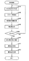
次に、血圧計1において測定者の最高血圧と最低血圧が測定される際に、CPU40が実行する処理(血圧測定処理)の内容について説明する。図5は、CPU40が実行する血圧測定処理のフローチャートである。
Next, the contents of the process (blood pressure measurement process) executed by the
図5を参照して、血圧測定処理では、CPU40は、まずステップSA10で、血圧測定用のカフ(空気袋13)の加圧を開始して、ステップSA20へ処理を進める。
Referring to FIG. 5, in the blood pressure measurement process, first, in step SA10,
ステップSA20では、CPU40は、マイク52から入力される信号に基づいてコロトコフ音の音量を検出して、ステップSA30へ処理を進める。
In step SA20,
ステップSA30では、CPU40は、ステップSA20で検出した音量に基づいて、スピーカ51から出力させる報知音の音量を決定して、ステップSA40へ処理を進める。なお、ステップSA30では、直前に実行されたステップSA20においてコロトコフ音が検出されなかった(音量が0であった)場合には、報知音の音量も0と決定される。
In step SA30,
また、ステップSA30では、ステップSA20で検出されたコロトコフ音の音量の値に対して、絶対的に、報知音の音量が決定される。つまり、ステップSA20で検出されるコロトコフ音の音量とステップSA30で決定される報知音の音量とは、それぞれ1対1で対応する関係を有している。CPU40は、たとえば、ステップSA20で検出されるコロトコフ音の音量の一次関数として、報知音の音量を決定する。もちろん、この音量の絶対値は、測定者によって調整可能とされても良い。
In step SA30, the volume of the notification sound is determined absolutely with respect to the value of the volume of the Korotkoff sound detected in step SA20. That is, the volume of the Korotkoff sound detected in step SA20 and the volume of the notification sound determined in step SA30 have a one-to-one correspondence relationship. For example, the
ステップSA40では、CPU40は、ステップSA30で決定した音量で、スピーカ51から報知音を出力させて、ステップSA50へ処理を進める。
In step SA40,
ステップSA50では、CPU40は、空気袋13の内圧Pが、上記した加圧目標である圧PMに到達したか否かを判断し、まだ到達していないと判断するとステップSA10へ処理を戻し、到達したと判断するとステップSA60へ処理を進める。
In step SA50, the
ステップSA60では、CPU40は、弁駆動回路27を適宜制御することにより、血圧測定用カフ(空気袋13)を一定の速度で減圧する処理を行ない、ステップSA70へ処理を進める。
In Step SA60, the
なお、ステップSA60における処理は、少なくとも、後述するステップSA80の処理が実行されるまで継続される。 Note that the process in step SA60 is continued until at least a process in step SA80 described later is executed.
次に、CPU40は、ステップSA70で、測定者の最高血圧を決定し、ステップSA80へ処理を進める。
Next, in step SA70,
ステップSA80では、CPU40は、測定者の最低血圧を決定する。
そして、最低血圧の決定が終了すると、CPU40は、血圧測定処理を終了させる。なお、ステップSA70における最高血圧の決定、および、ステップSA80における最低血圧の決定については、周知の技術を採用することができるため、ここでは詳細な説明は繰返さない。
In step SA80, the
When the determination of the minimum blood pressure is completed, the
以上図5を参照して説明した血圧測定処理では、空気袋13の内圧(カフ圧)が圧PMまで上昇された後、当該カフ圧が一定の速度で減少される状況下で、測定者の最高血圧および最低血圧が決定される。そして、カフ圧が圧PMまで上昇される期間、コロトコフ音の音量に対応する音量で、スピーカ51から報知音が出力される。
In the blood pressure measurement process described above with reference to FIG. 5, after the internal pressure (cuff pressure) of the
図4(B)を参照して説明したように、コロトコフ音の音量は、カフ圧が測定者の最低血圧から最高血圧まで変化する期間において、まず増加し、その後、極大値を示した後減少する。また、ステップSA40で出力される報知音の音量は、上記したように、コロトコフ音の音量に対して絶対的に(1対1で対応するように)決定される。したがって、本実施の形態の血圧測定処理によれば、測定者は、予備的な加圧工程において、当該測定者のコロトコフ音の音量の変化を、報知音の音量に基づいて認識することができる。このことにより、測定者は、カフ圧が最低血圧値を超えたこと、あるいは、カフ圧が最高血圧を超えたことに基づいて、加圧がもうすぐ終わることを知ることができる。 As described with reference to FIG. 4B, the volume of the Korotkoff sound first increases during the period in which the cuff pressure changes from the lowest blood pressure of the measurer to the highest blood pressure, and then decreases after showing the maximum value. To do. Further, as described above, the volume of the notification sound output in step SA40 is determined absolutely (in a one-to-one correspondence) with respect to the volume of the Korotkoff sound. Therefore, according to the blood pressure measurement process of the present embodiment, the measurer can recognize the change in the volume of the Korotkoff sound of the measurer based on the volume of the notification sound in the preliminary pressurizing step. . Thus, the measurer can know that pressurization is almost over based on the cuff pressure exceeding the minimum blood pressure value or the cuff pressure exceeding the maximum blood pressure.
なお、以上説明した本実施の形態では、カフ圧が上昇する工程におけるコロトコフ音の音量に応じて、出力される報知音の音量が、決定されていた。ここで、コロトコフ音の音量に応じて変化するものが、報知音の音程(ピッチ数)とされてもよい。また、コロトコフ音の音量の変化に応じて、出力する報知音のリズム(たとえば、連続して出力される報知音の出力される時間間隔)とされてもよい。また、コロトコフ音の音量についての範囲を設定し、当該範囲ごとに異なる楽曲を出力するようにされても良い。 In the present embodiment described above, the volume of the notification sound to be output is determined according to the volume of the Korotkoff sound in the process of increasing the cuff pressure. Here, what changes according to the volume of the Korotkoff sound may be the pitch (number of pitches) of the notification sound. Further, the rhythm of the notification sound to be output (for example, the time interval at which the continuously output notification sound is output) may be set according to the change in the volume of the Korotkoff sound. Further, a range for the volume of the Korotkoff sound may be set, and a different piece of music may be output for each range.
[第2の実施の形態]
上記した第1の実施の形態では、血圧計1において、マイク52によって検出されるコロトコフ音の大きさの変化に対応して変化する報知音が出力された。これにより、測定者は、カフによる圧迫の度合が上昇する期間において、カフ圧が当該測定者の最高血圧に近づき、また、最高血圧を超えたことを、報知音の音量の減少、報知音の出力の停止によって、それぞれ認識することができる。これは、図4(A)および図4(B)を参照して説明したように、測定者のコロトコフ音の音量が、最高血圧である圧P2の近傍ではカフ圧の上昇とともに減少し、また、圧P2を超えるとコロトコフ音が消失することに対応している。
[Second Embodiment]
In the first embodiment described above, the
一方、図4(C)を参照して説明したように、測定者の脈波振幅も、同様の態様で変化する。つまり、図4(C)において点線で示された脈波振幅の稜線からも明らかなように、血圧計1においてカフ圧が上昇した場合、測定者の最低血圧である圧P1にカフ圧が到達するまでは、脈波振幅は緩やかに上昇し、そして、カフ圧が最低血圧の圧P1を過ぎると、脈波振幅は上昇する度合を上げ、極大値を経た後、比較的早く減少し、そして、最高血圧である圧P2を超えた後は、その減少の度合が緩やかなものとなる。
On the other hand, as described with reference to FIG. 4C, the pulse wave amplitude of the measurer also changes in the same manner. That is, as apparent from the ridge line of the pulse wave amplitude indicated by the dotted line in FIG. 4C, when the cuff pressure increases in the
図6に、図5を参照して説明した血圧測定処理においてコロトコフ音の音量に応じて報知音の音量を決定していたところを、脈波振幅に応じて報知音の音量を決定するようにした変形例のフローチャートを示す。 In FIG. 6, the volume of the notification sound is determined according to the volume of the Korotkoff sound in the blood pressure measurement process described with reference to FIG. 5, but the volume of the notification sound is determined according to the pulse wave amplitude. The flowchart of the modified example shown is shown.
図6を参照して、この変形例では、ステップSB10では、CPU40は、ステップSA10(図5参照)と同様に空気袋13(血圧測定用カフ)の加圧を開始する。
Referring to FIG. 6, in this modification, in step SB10,
そして、ステップSB20で、圧力センサ23において検出される脈波(図4(A)において点線で示されたもの)に基づいて脈波振幅を算出し、ステップSB30で、直前のステップSB20で算出した脈波振幅の値に基づいてスピーカ51から出力する報知音の音量を決定する。
In step SB20, the pulse wave amplitude is calculated based on the pulse wave detected by the pressure sensor 23 (indicated by the dotted line in FIG. 4A), and in step SB30, the pulse wave amplitude is calculated in the immediately preceding step SB20. The volume of the notification sound output from the
そして、ステップSB40で、CPU40は、ステップSB30で決定した音量の報知音を、スピーカ51から出力させ、ステップSB50で、カフ圧Pが加圧目標である圧PMに到達したか否かを判断する。
Then, in step SB40, the
そして、到達していないと判断するとステップSB10へ処理を戻す。つまり、カフ圧が圧PMに到達するまで、カフ圧が一定の速度で上昇されるとともに、脈波振幅の値に対応した音量の報知音がスピーカ51から出力される。
If it is determined that it has not been reached, the process returns to step SB10. That is, until the cuff pressure reaches the pressure PM, the cuff pressure is increased at a constant speed, and a notification sound having a volume corresponding to the value of the pulse wave amplitude is output from the
一方、カフ圧Pが圧PMに到達した後は、ステップSA60〜ステップSA80と同様に、ステップSB60で空気袋13の減圧が開始され、ステップSB70で最高血圧が決定され、ステップSB80で最低血圧が決定されて、血圧測定処理が終了する。
On the other hand, after the cuff pressure P reaches the pressure PM, the decompression of the
[第3の実施の形態]
以上説明した第1および第2の本実施の形態のように、カフ圧を上昇させる工程において測定者のコロトコフ音の音量や脈波振幅の値の大きさに絶対的に対応した音量で報知音を出力する場合、制御を容易なものとすることができる一方で、コロトコフ音や脈波振幅の変化の度合の小さい測定者や、コロトコフ音の音量や脈波振幅の絶対値が全体的に小さい測定者については、報知音の音量の変化によっては、カフ圧が最高血圧に近づいたり、最高血圧を超えることにより、加圧工程が終了に近づいていることを認識しにくい場合も考えられる。
[Third Embodiment]
As in the first and second embodiments described above, in the step of increasing the cuff pressure, the notification sound has a volume that absolutely corresponds to the volume of the Korotkoff sound and the value of the pulse wave amplitude of the measurer. Can be controlled easily, while measuring person with small degree of change of Korotkoff sound and pulse wave amplitude, and absolute value of Korotkoff sound volume and pulse wave amplitude are generally small For the measurer, depending on the change in the volume of the notification sound, it may be difficult to recognize that the pressurization process is nearing the end because the cuff pressure approaches the maximum blood pressure or exceeds the maximum blood pressure.
このことを、図7(A)〜図7(C)を参照してより具体的に説明する。
図7(A)は、カフ圧が時間の経過に従って変化する状態が示されている。具体的には、ある測定者の最低血圧である圧P1よりも低い値から、加圧目標である圧PMまでカフ圧が上昇し、その後カフ圧が減少する状態が示されている。
This will be described more specifically with reference to FIGS. 7A to 7C.
FIG. 7A shows a state in which the cuff pressure changes as time passes. Specifically, a state is shown in which the cuff pressure increases from a value lower than the pressure P1 that is the minimum blood pressure of a certain measurer to the pressure PM that is the pressurization target, and then the cuff pressure decreases.
図7(B)と図7(C)は、最低血圧が圧P1であり最高血圧が圧P2である測定者の、図7(A)に示されたカフ圧の変化に対応する脈波振幅の変化をそれぞれ示している。 FIGS. 7B and 7C show the pulse wave amplitude corresponding to the change in the cuff pressure shown in FIG. 7A of the measurer whose minimum blood pressure is pressure P1 and maximum blood pressure is pressure P2. Each change is shown.
なお、図7(C)に示されたグラフの方が、図7(B)に示されたグラフよりも、全体的に脈波振幅の値が大きくなっている。つまり、図7(C)の最大の脈波振幅が振幅W1となっているのに対し、図7(B)に示されたグラフでは、同じカフ圧に対応する脈波振幅であって当該グラフでの脈波振幅の極大値は、図7(C)に示された振幅W1には到達していない。 In addition, the value of the pulse wave amplitude is generally larger in the graph shown in FIG. 7C than in the graph shown in FIG. That is, while the maximum pulse wave amplitude in FIG. 7C is the amplitude W1, in the graph shown in FIG. 7B, the pulse wave amplitude corresponding to the same cuff pressure is The maximum value of the pulse wave amplitude at 1 does not reach the amplitude W1 shown in FIG.
図7(B)に示された脈波振幅の変化の態様と、図7(C)に示された脈波振幅の変化の態様は、似てはいるが、全体的に、図7(B)に示された方が脈波振幅の値が全体的に小さい。このため、図6を参照して説明した処理に従って報知音が制御された場合、図7(C)に示された場合よりも、出力される音量の変化は小さいものとなると考えられる。したがって、このような場合、測定者は、音量の変化を認識しにくく、このことから、脈波振幅の変化に応じ、音量が一度大きくなった後小さくなることによって加圧工程が終わりに近づいていることを認識しにくいと考えられる。 Although the aspect of the change of the pulse wave amplitude shown in FIG. 7B and the aspect of the change of the pulse wave amplitude shown in FIG. 7C are similar, overall, FIG. ) Shows a smaller pulse wave amplitude overall. For this reason, when the notification sound is controlled according to the process described with reference to FIG. 6, it is considered that the change in the output volume is smaller than that in the case illustrated in FIG. Therefore, in such a case, it is difficult for the measurer to recognize the change in the volume. From this, according to the change in the pulse wave amplitude, the pressurization process approaches the end by decreasing the volume once and then decreasing. It is considered difficult to recognize.
このような事態に対応するために、報知音の音量を、第2の実施の形態で説明したような脈波振幅、または、第1の実施の形態において説明したようなコロトコフ音の音量の、極大値に対する比に対応して決定することが考えられる。 In order to cope with such a situation, the volume of the notification sound is the pulse wave amplitude as described in the second embodiment, or the volume of the Korotkoff sound as described in the first embodiment. It may be determined corresponding to the ratio to the maximum value.
つまり、本実施の形態の血圧計は、たとえば、カフ圧を上昇させたときに、コロトコフ音の音量または脈波振幅が極大値を呈するまで、一定の音量で報知音を出力する。そして、コロトコフ音の音量または脈波振幅の極大値が検出された後は、カフ圧の加圧工程が終了するまで、コロトコフ音の音量の極大値または脈波振幅の極大値に対するそれぞれの測定値の比に応じて報知音の音量を決定し、当該決定された音量で報知音を出力する。 That is, for example, when the cuff pressure is increased, the sphygmomanometer according to the present embodiment outputs the notification sound at a constant volume until the volume of the Korotkoff sound or the pulse wave amplitude exhibits a maximum value. After the maximum value of the Korotkoff sound volume or pulse wave amplitude is detected, the respective measured values for the maximum value of the Korotkoff sound volume or the maximum value of the pulse wave amplitude until the cuff pressure pressurization process is completed. The sound volume of the notification sound is determined in accordance with the ratio, and the notification sound is output at the determined sound volume.
また、本実施の形態の血圧計では、脈波振幅が極大値(最大値)をとった後の報知音の出力態様は、脈波振幅が極大値(最大値)をとった時点で、脈波振幅の値と報知音の音量との対応関係を修正することによって決定されても良い。 Further, in the sphygmomanometer of the present embodiment, the notification sound output mode after the pulse wave amplitude has reached the maximum value (maximum value) is the time when the pulse wave amplitude has reached the maximum value (maximum value). It may be determined by correcting the correspondence between the value of the wave amplitude and the volume of the notification sound.
具体的には、脈波振幅の最大値が検出された時点で、カフへの加圧開始時の脈波振幅とその最大の振幅との間で、報知音の最低音量と最高音量とが割り振られるように、脈波振幅の測定値と出力される報知音の音量との関係の正規化がなされる。そして、上記の最大値検出以降は、上記のように正規化された後の関係に基づいて、脈波振幅の測定値に対する報知音の音量が決定される。 Specifically, when the maximum value of the pulse wave amplitude is detected, the minimum volume and maximum volume of the notification sound are allocated between the pulse wave amplitude at the start of pressurization to the cuff and the maximum amplitude. As described above, the relationship between the measured value of the pulse wave amplitude and the volume of the notification sound to be output is normalized. After detecting the maximum value, the volume of the notification sound with respect to the measured value of the pulse wave amplitude is determined based on the relationship after normalization as described above.
このような正規化によって脈波振幅の値と報知音の音量との対応関係が修正されることにより、たとえば、図7(B)に示したような検出結果に対して脈波振幅がW3からW4まで変化する際に脈波振幅の値に応じて変化する報知音の音量の変化量と、図7(C)に示したような検出結果に対して脈波振幅がW1からW2まで変化する際に脈波振幅の値に応じて変化する報知音の音量の変化量とが同じ量とされる。より具体的には、脈波振幅が最大値をとった後、図7(C)の例では、脈波振幅がW1からW2まで変化する際にも報知音の音量が40dBから30dB変化するのに対し、図7(B)の例では、脈波振幅の変化はW1からW2よりも小さいW3からW4までの変化であっても、報知音の音量の変化は40dBから30dBへと、つまり、図7(C)の例と同じ量だけ変化する。 By correcting the correspondence between the value of the pulse wave amplitude and the volume of the notification sound by such normalization, for example, the pulse wave amplitude is changed from W3 to the detection result as shown in FIG. The pulse wave amplitude changes from W1 to W2 with respect to the change amount of the volume of the notification sound that changes according to the value of the pulse wave amplitude when changing to W4 and the detection result as shown in FIG. In this case, the amount of change in the volume of the notification sound that changes according to the value of the pulse wave amplitude is the same amount. More specifically, after the pulse wave amplitude takes the maximum value, in the example of FIG. 7C, the volume of the notification sound changes from 40 dB to 30 dB even when the pulse wave amplitude changes from W1 to W2. On the other hand, in the example of FIG. 7B, even if the change of the pulse wave amplitude is a change from W3 to W4 smaller than W1 to W2, the change in the volume of the notification sound is from 40 dB to 30 dB, that is, It changes by the same amount as in the example of FIG.
[第4の実施の形態]
本実施の形態の血圧測定用装置は、その構成を、上記した第1の実施の形態の血圧計1と同様のものとすることができる。なお、本実施の形態の血圧計1は、上記した第1の実施の形態に対して、血圧測定処理における処理内容が異なる。したがって、以下、本実施の形態において実行される血圧測定処理の内容を説明する。
[Fourth Embodiment]
The blood pressure measurement device according to the present embodiment can have the same configuration as the blood pressure monitor 1 according to the first embodiment described above. The
図8は、本実施の形態のCPU40が実行する血圧測定処理のフローチャートである。
図8を参照して、血圧測定処理では、CPU40は、まずステップSA1で、測定者からのユーザIDの入力を受付けるために待機する。
FIG. 8 is a flowchart of blood pressure measurement processing executed by the
Referring to FIG. 8, in the blood pressure measurement process, first, in step SA1,
そして、操作部3に対してユーザIDが入力されると、ステップSA2で、当該ユーザIDに対応してメモリ部41において記憶している最大音量の読出を行なう。
When a user ID is input to the
なお表1に、本実施の形態の血圧計1のメモリ部41に記憶されているユーザ情報の一例を示す。
Table 1 shows an example of user information stored in the memory unit 41 of the

本実施の形態のメモリ部41では、表1に示されるように、各測定者を同定するユーザIDと、各測定者の前回の血圧測定時のコロトコフ音の音量の最大値に対応する数値である最大音量とが互いに関連付けられている。 In the memory unit 41 of the present embodiment, as shown in Table 1, a user ID for identifying each measurer and a numerical value corresponding to the maximum value of the volume of the Korotkoff sound at the time of the last blood pressure measurement of each measurer. A certain maximum volume is associated with each other.
ステップSA2では、CPU40は、ユーザ情報において、操作部3に入力されたユーザIDと関連付けられて記憶された最大音量を読出す。
In step SA2,
ステップSA10では、CPU40は、図5を参照して説明した血圧測定処理におけるステップSA10と同様に、空気袋13の加圧を開始し、ステップSA20へ処理を進める。
In step SA10, the
ステップSA20では、CPU40は、マイク52から入力される音声に基づいてコロトコフ音を検出し、ステップSA31へ処理を進める。
In step SA20, the
ステップSA31では、CPU40は、ステップSA2で読出した最大音量に対する、直前で実行したステップSA20で検出したコロトコフ音の音量に基づいて、報知音の音量を決定して、ステップSA40へ処理を進める。
In step SA31, the
ステップSA40では、直前で実行したステップSA31で決定した音量で、スピーカ51から報知音を出力して、ステップSA50へ処理を進める。
In step SA40, a notification sound is output from the
ステップSA50では、CPU40は、カフ圧Pが圧PMに到達したか否かを判断し、到達していないと判断するとステップSA10へ処理を戻す。一方、到達したと判断すると、CPU40は、ステップSA60へ処理を進める。
In step SA50, the
ステップSA60〜ステップSA80の処理内容は、図5を参照して説明した各処理と同様であるため、ここでは説明を繰返さない。 Since the processing contents of steps SA60 to SA80 are the same as those described with reference to FIG. 5, description thereof will not be repeated here.
以上説明した本実施の形態では、測定者ごとに、過去の当該測定者の平均血圧に対応するコロトコフ音の音量と考えられる、最大音量が、予め記憶されている。そして、空気袋13の加圧工程では、図4(B)を参照して説明したようにコロトコフ音の音量が変化した場合、測定されたコロトコフ音の音量の、各測定者についての差大音量(表1参照)に対する比が算出され、そして、当該比に応じて決定される音量の報知音が、スピーカ51から出力される。
In the present embodiment described above, for each measurer, a maximum volume that is considered to be the volume of the Korotkoff sound corresponding to the past average blood pressure of the measurer is stored in advance. And in the pressurization process of the
[第5の実施の形態]
本実施の形態の血圧測定用装置は、第1の実施の形態において図6を参照して説明した、カフ圧の上昇工程においてスピーカ51から出力される報知音の音量を、測定者の脈波振幅に応じて変化させる場合において、図8を参照して説明したようにユーザ情報を用いて報知音の音量を変化させる場合について説明する。なお、本実施の形態の血圧計1は、上記した第1の実施の形態に対して、血圧測定処理における処理内容が異なる。したがって、以下、本実施の形態において実行される血圧測定処理の内容を説明する。
[Fifth Embodiment]
The blood pressure measurement device according to the present embodiment uses the volume of the notification sound output from the
本実施の形態の血圧計1では、メモリ部41には、ユーザ情報として表2に示すような情報が記憶されている。
In the
表2に示されたユーザ情報では、表1において、各測定者のコロトコフ音の最大音量がユーザIDと関連付けられて記憶されていたのに対し、各測定者の前回測定時の脈波振幅の最大値(最大脈波振幅)が、ユーザIDに関連付けられて記憶されている。 In the user information shown in Table 2, while the maximum volume of the Korotkoff sound of each measurer is stored in association with the user ID in Table 1, the pulse wave amplitude of each measurer at the time of the previous measurement is stored. The maximum value (maximum pulse wave amplitude) is stored in association with the user ID.
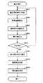
また、このようにカフ圧の上昇工程において報知音の音量の制御が行なわれる場合の血圧測定処理のフローチャートを図9に示す。 FIG. 9 shows a flowchart of the blood pressure measurement process when the volume of the notification sound is controlled in the cuff pressure increasing process.
図9を参照して、血圧測定処理では、まずステップSB1において、図8を参照して説明したステップSA1と同様に、CPU40は、操作部3に対するユーザIDの入力がなされるまで待機する。
With reference to FIG. 9, in the blood pressure measurement process, first, in step SB <b> 1, similarly to step SA <b> 1 described with reference to FIG. 8,
そして、ユーザIDが入力されると、CPU40は、ステップSB2において、表2に示されたようなユーザ情報から、ステップSB1において入力を受付けたユーザIDに関連付けられて記憶されている最大脈波振幅を読出して、ステップSB10に処理を進める。
Then, when the user ID is input, the
ステップSB10では、図6を参照して説明したステップSB10と同様に、空気袋13の内圧を一定の速度で上昇させる処理を開始し、ステップSB20へ処理を進める。
In step SB10, similarly to step SB10 described with reference to FIG. 6, a process for increasing the internal pressure of the
ステップSB20では、CPU40は、脈波振幅を算出し、ステップSB31へ処理を進める。
In step SB20,
ステップSB31では、直前のステップSB20で算出した脈波振幅の、ステップSB2で読出した最大脈波振幅に対する比を算出し、当該比に基づいて、スピーカ51から出力させる報知音の音量を決定し、ステップSB40へ処理を進める。
In step SB31, the ratio of the pulse wave amplitude calculated in the immediately preceding step SB20 to the maximum pulse wave amplitude read in step SB2 is calculated, and the volume of the notification sound to be output from the
ステップSB40では、CPU40は、直前のステップSB31で決定した音量でスピーカ51から報知音を出力し、ステップSB50へ処理を進める。
In step SB40,
ステップSB50では、CPU40は、空気袋13の内圧(カフ圧P)が、上昇目標である圧PMに到達したか否かを判断し、到達していないと判断するとステップSB10へ処理を戻し、到達したと判断するとステップSB60へ処理を進める。
In step SB50, the
ステップSB60〜ステップSB80については、CPU40は、図6を参照して説明した各ステップにおける処理と同様の処理を実行する。
For step SB60 to step SB80, the
そして、ステップSB80の処理を実行した後、CPU40は、ステップSB90で、表2に示されるようなユーザ情報の、ステップSB1で入力を受付けたユーザIDについての最大脈波振幅を、今回実行した血圧測定処理における脈波振幅の最大値で更新して、血圧測定処理を終了させる。
After executing the process of step SB80, in step SB90, the
[その他の変形例等]
以上説明した各実施の形態では、カフ圧を最高血圧よりも高い圧まで上昇させた後、カフ圧を減少させる工程において、最高血圧および最低血圧を測定(決定)する血圧測定用装置が例示されていた。そして、当該血圧測定用装置において、カフ圧を上昇させる工程において、測定者の脈波情報から求められる数値(たとえば、コロトコフ音の音量、脈波振幅、等)の変化に応じて変化する音声が、スピーカから出力されていた。なお、本発明が適用されるのは、カフ圧の減少工程において血圧測定が行なわれるタイプの血圧測定用装置に限定されない。つまり、たとえば、カフ圧を上昇させる工程において、最高血圧および最低血圧の測定を行なうような血圧測定用装置においても、当該カフ圧を上昇させる工程で、測定者の脈波情報から求められる数値の変化に応じて変化する音声を出力させることによって本発明を適用することができる。
[Other variations]
Each of the embodiments described above exemplifies a blood pressure measurement device that measures (determines) the maximum blood pressure and the minimum blood pressure in the step of decreasing the cuff pressure after increasing the cuff pressure to a pressure higher than the maximum blood pressure. It was. In the blood pressure measurement device, in the step of increasing the cuff pressure, a sound that changes in accordance with changes in numerical values (for example, the volume of the Korotkoff sound, the pulse wave amplitude, etc.) obtained from the pulse wave information of the measurer. , Was output from the speaker. It should be noted that the present invention is not limited to a blood pressure measuring device of a type in which blood pressure is measured in the cuff pressure reducing process. That is, for example, even in a blood pressure measurement device that measures the maximum blood pressure and the minimum blood pressure in the step of increasing the cuff pressure, the numerical value obtained from the pulse wave information of the measurer in the step of increasing the cuff pressure The present invention can be applied by outputting a sound that changes in accordance with a change.
また、本発明は、報知音を出力できる機能を有する装置に対して、カフに圧迫されて生じる動脈の容積変化に基づいて抽出される、コロトコフ音や脈波などの脈波情報、または、これらから得られるコロトコフ音の音量値や脈波振幅などの値が入力し、この値に対応した音量が出力するように制御されることによっても、同様の作用効果を奏することが考えられる。つまり、本発明は、以上説明した各実施の形態における血圧計自体に音声を出力する機能が備えられていない場合であって、当該血圧計が他の音声を出力できる機器に対して、各実施の形態において当該血圧計が出力していた態様と同様の態様で音量等を変化させながら報知音を出力するための情報を出力することも、その技術的範囲に含むことが意図される。このように構成された場合、各実施の形態の血圧計は、音声出力用装置として機能することになる。なお、血圧計は、音声を出力する機能を備えていても、他の機器に音声を出力するための情報を送信できるよう構成されても構わないことは言うまでもない。 In addition, the present invention provides pulse wave information such as Korotkoff sounds and pulse waves, which are extracted based on a change in the volume of an artery caused by being compressed by a cuff for a device having a function capable of outputting a notification sound, or these It is conceivable that the same effect can be obtained by inputting a value such as a volume value or pulse wave amplitude of Korotkoff sound obtained from the above and controlling the sound volume corresponding to this value to be output. That is, the present invention is a case where the sphygmomanometer itself in each of the embodiments described above is not provided with a function of outputting a sound, and the sphygmomanometer is provided for each device that can output other sound. It is intended that the technical scope also includes outputting the information for outputting the notification sound while changing the volume or the like in a manner similar to the manner that the blood pressure monitor has outputted in the form. When configured in this manner, the sphygmomanometer of each embodiment functions as a sound output device. Needless to say, the sphygmomanometer may have a function of outputting sound, or may be configured to transmit information for outputting sound to other devices.
また、以上説明した各実施の形態では、測定者の上腕部に空気袋を含むカフを装着して血圧を測定する血圧計が例示されたが、本発明が適用される血圧測定用装置はこのようなタイプのものに限定されない。たとえば、手首にカフが装着されることにより撓骨動脈を介して脈波を検出し、検出された脈波信号に基づいて血圧が測定されるタイプ等、他のタイプの血圧測定用装置に適用されても良い。 Further, in each of the embodiments described above, a sphygmomanometer that measures blood pressure by wearing a cuff including an air bag on the upper arm of the measurer is exemplified, but the blood pressure measurement device to which the present invention is applied is this It is not limited to such a type. For example, applied to other types of blood pressure measurement devices, such as a type that detects a pulse wave via the radial artery by attaching a cuff to the wrist and measures the blood pressure based on the detected pulse wave signal May be.
今回開示された各実施の形態はすべての点で例示であって制限的なものではないと考えられるべきである。本発明の範囲は上記した説明ではなくて特許請求の範囲によって示され、特許請求の範囲と均等の意味および範囲内でのすべての変更が含まれることが意図される。また、本願明細書の各実施の形態において例示された技術は、可能な限り組み合わされて実現されることが意図される。 Each embodiment disclosed this time must be considered as illustrative in all points and not restrictive. The scope of the present invention is defined by the terms of the claims, rather than the description above, and is intended to include any modifications within the scope and meaning equivalent to the terms of the claims. In addition, it is intended that the techniques exemplified in the embodiments of the present specification are combined and realized as much as possible.
1 血圧計、2 本体、3 操作部、4 表示部、5 測定部、6 ハウジング、7 カバー、13 空気袋、20 測定用エアー系統、21 ポンプ、22 弁、23 圧力センサ、26 ポンプ駆動回路、27 弁駆動回路、28 増幅器、29 A/D、40 CPU、41 メモリ部、51 スピーカ、52 マイク。
DESCRIPTION OF
Claims (10)
前記カフに圧迫されて生じる前記動脈の容積変化より脈波情報を抽出するための脈波情報抽出手段と、
前記カフ圧制御手段が前記カフ圧を上昇させている期間に音声を出力する出力手段と、
前記出力手段が出力する音声を、前記脈波情報抽出手段によって抽出された前記脈波情報から求められる数値の変化に応じて変化させる出力制御手段とをさらに備える、血圧測定用装置。 A cuff pressure for controlling a cuff pressure, which is a fluid bag included in a cuff to be attached to a predetermined part of a living body and compresses an artery, and which is inflated when a fluid is supplied. Control means;
Pulse wave information extracting means for extracting pulse wave information from a volume change of the artery caused by being compressed by the cuff;
Output means for outputting sound during a period when the cuff pressure control means increases the cuff pressure;
An apparatus for blood pressure measurement, further comprising: output control means for changing the sound output from the output means in accordance with a change in a numerical value obtained from the pulse wave information extracted by the pulse wave information extraction means.
前記出力制御手段は、前記脈波情報から求められる数値であるコロトコフ音の音量の変化に応じて前記出力手段が出力する音声の音量を制御する、請求項1に記載の血圧測定用装置。 The pulse wave information extracted by the pulse wave information extraction means is a Korotkoff sound,
The blood pressure measurement device according to claim 1, wherein the output control unit controls the volume of the sound output from the output unit in accordance with a change in the volume of the Korotkoff sound, which is a numerical value obtained from the pulse wave information.
前記出力制御手段は、前記記憶手段に記憶された数値に対する、前記脈波情報から求められる数値の比の変化に応じて、前記出力手段が出力する音声を変化させる、請求項1〜請求項5のいずれかに記載の血圧測定用装置。 Storage means for storing a numerical value obtained from the pulse wave information at the time when the average blood pressure of the living body is measured;
The output control means changes sound output by the output means in accordance with a change in a ratio of a numerical value obtained from the pulse wave information to a numerical value stored in the storage means. The blood pressure measurement device according to any one of the above.
前記カフの内圧であるカフ圧が上昇する期間に音声を出力する出力手段と、
前記出力手段が出力する音声を、前記受信手段が受信した前記脈波情報から求められる数値の変化に応じて変化させる出力制御手段とをさらに備える、音声出力用装置。 Receiving means for receiving pulse wave information for extracting pulse wave information from a volume change of the artery generated by being compressed by a cuff for being attached to a predetermined part of a living body and compressing an artery;
Output means for outputting sound during a period when the cuff pressure, which is the internal pressure of the cuff, rises;
An audio output device further comprising: output control means for changing the sound output from the output means in accordance with a change in a numerical value obtained from the pulse wave information received by the receiving means.
Priority Applications (1)
| Application Number | Priority Date | Filing Date | Title |
|---|---|---|---|
| JP2008081328A JP2009233012A (en) | 2008-03-26 | 2008-03-26 | Blood measuring device and sound output device |
Applications Claiming Priority (1)
| Application Number | Priority Date | Filing Date | Title |
|---|---|---|---|
| JP2008081328A JP2009233012A (en) | 2008-03-26 | 2008-03-26 | Blood measuring device and sound output device |
Publications (1)
| Publication Number | Publication Date |
|---|---|
| JP2009233012A true JP2009233012A (en) | 2009-10-15 |
Family
ID=41247722
Family Applications (1)
| Application Number | Title | Priority Date | Filing Date |
|---|---|---|---|
| JP2008081328A Withdrawn JP2009233012A (en) | 2008-03-26 | 2008-03-26 | Blood measuring device and sound output device |
Country Status (1)
| Country | Link |
|---|---|
| JP (1) | JP2009233012A (en) |
Cited By (2)
| Publication number | Priority date | Publication date | Assignee | Title |
|---|---|---|---|---|
| WO2011122293A1 (en) * | 2010-03-30 | 2011-10-06 | オムロンヘルスケア株式会社 | Blood-pressure measuring device, and recording medium |
| CN108882876A (en) * | 2016-05-16 | 2018-11-23 | 卫保数码有限公司 | Method for obtaining blood pressure of person and device thereof |
-
2008
- 2008-03-26 JP JP2008081328A patent/JP2009233012A/en not_active Withdrawn
Cited By (3)
| Publication number | Priority date | Publication date | Assignee | Title |
|---|---|---|---|---|
| WO2011122293A1 (en) * | 2010-03-30 | 2011-10-06 | オムロンヘルスケア株式会社 | Blood-pressure measuring device, and recording medium |
| JP2011206322A (en) * | 2010-03-30 | 2011-10-20 | Omron Healthcare Co Ltd | Blood pressure measuring device, and program for blood pressure measurement |
| CN108882876A (en) * | 2016-05-16 | 2018-11-23 | 卫保数码有限公司 | Method for obtaining blood pressure of person and device thereof |
Similar Documents
| Publication | Publication Date | Title |
|---|---|---|
| US20110257540A1 (en) | Electronic sphygmomanometer and blood pressure measuring method | |
| JP5565164B2 (en) | Electronic blood pressure monitor | |
| JP2004041244A (en) | Instrument for evaluating vascular endothelium function | |
| WO2000049943A1 (en) | Blood pressure measuring device and pulse wave detecting device | |
| JP2009284966A (en) | Blood pressure information measuring instrument and indicator acquisition method | |
| JP4220980B2 (en) | Blood pressure measurement device | |
| JP2003250770A (en) | Electronic sphygmomanometer | |
| JP3898980B2 (en) | Blood pressure measuring device and method using linearly variable air pressure | |
| KR101081659B1 (en) | Auto-diagnostic blood manometer | |
| JP2009082175A (en) | Respiration training instrument and computer program | |
| JP5412740B2 (en) | Blood pressure measurement device | |
| JP2009284965A (en) | Blood pressure information measuring instrument | |
| JP2009233012A (en) | Blood measuring device and sound output device | |
| JP2004057362A (en) | Blood pressure monitoring device | |
| JP3726650B2 (en) | Sphygmomanometer | |
| KR101094163B1 (en) | Apparatus and method for measuring blood pressure using proximity sensor | |
| JP6375123B2 (en) | Blood pressure measurement technology acquisition support device and blood pressure measurement technology acquisition method | |
| JP2938238B2 (en) | Atherosclerosis measuring device | |
| TW471956B (en) | Digital blood pressure measuring method and device thereof | |
| JP2011200610A (en) | Electronic sphygmomanometer | |
| WO2021074954A1 (en) | Electronic device, display method of electronic device, and display program of electronic device | |
| JP2004195070A (en) | Automatic sphygmomanometer | |
| JP2010167181A (en) | Electronic manometer, information processor, measuring management system, measuring management program, and measuring management method | |
| JP2012115413A (en) | Electronic sphygmomanometer | |
| EP1340455A1 (en) | Standard pulse-wave-propagation-velocity-related-value determining apparatus and pulse wave-propagation-velocity-related-value obtaining apparatus |
Legal Events
| Date | Code | Title | Description |
|---|---|---|---|
| A300 | Withdrawal of application because of no request for examination |
Free format text: JAPANESE INTERMEDIATE CODE: A300 Effective date: 20110607 |