JP2009232103A - Radio apparatus - Google Patents
Radio apparatus Download PDFInfo
- Publication number
- JP2009232103A JP2009232103A JP2008074271A JP2008074271A JP2009232103A JP 2009232103 A JP2009232103 A JP 2009232103A JP 2008074271 A JP2008074271 A JP 2008074271A JP 2008074271 A JP2008074271 A JP 2008074271A JP 2009232103 A JP2009232103 A JP 2009232103A
- Authority
- JP
- Japan
- Prior art keywords
- circuit
- communication control
- control circuit
- signal
- received signal
- Prior art date
- Legal status (The legal status is an assumption and is not a legal conclusion. Google has not performed a legal analysis and makes no representation as to the accuracy of the status listed.)
- Granted
Links
Images
Classifications
-
- Y—GENERAL TAGGING OF NEW TECHNOLOGICAL DEVELOPMENTS; GENERAL TAGGING OF CROSS-SECTIONAL TECHNOLOGIES SPANNING OVER SEVERAL SECTIONS OF THE IPC; TECHNICAL SUBJECTS COVERED BY FORMER USPC CROSS-REFERENCE ART COLLECTIONS [XRACs] AND DIGESTS
- Y02—TECHNOLOGIES OR APPLICATIONS FOR MITIGATION OR ADAPTATION AGAINST CLIMATE CHANGE
- Y02D—CLIMATE CHANGE MITIGATION TECHNOLOGIES IN INFORMATION AND COMMUNICATION TECHNOLOGIES [ICT], I.E. INFORMATION AND COMMUNICATION TECHNOLOGIES AIMING AT THE REDUCTION OF THEIR OWN ENERGY USE
- Y02D30/00—Reducing energy consumption in communication networks
- Y02D30/70—Reducing energy consumption in communication networks in wireless communication networks
Landscapes
- Mobile Radio Communication Systems (AREA)
Abstract
【課題】消費電力を低減することができる無線装置を得る。
【解決手段】無線装置は、受信信号を受信する受信回路10と、受信信号を処理する通信制御回路12とを備える。受信回路10は、復調回路14、検出回路16及びデータ保存回路18を有する。復調回路14は、受信信号を復調データに復調する。検出回路16は、復調データを解析して、受信信号に自分宛て信号が有るか無いかを検出する。データ保存回路18は、復調データを保存する。
【選択図】図1A wireless device capable of reducing power consumption is obtained.
A wireless device includes a receiving circuit that receives a received signal and a communication control circuit that processes the received signal. The reception circuit 10 includes a demodulation circuit 14, a detection circuit 16, and a data storage circuit 18. The demodulation circuit 14 demodulates the received signal into demodulated data. The detection circuit 16 analyzes the demodulated data and detects whether there is a signal addressed to the received signal. The data storage circuit 18 stores demodulated data.
[Selection] Figure 1
Description
本発明は、受信信号を受信する受信回路と、受信信号を処理する通信制御回路とを備えた無線装置に関し、特に消費電力を低減することができる無線装置に関するものである。 The present invention relates to a radio apparatus including a reception circuit that receives a reception signal and a communication control circuit that processes the reception signal, and particularly relates to a radio apparatus that can reduce power consumption.
受信信号を受信する受信回路と、受信信号を処理する通信制御回路とを備えた無線装置が用いられている。このような無線装置において、受信信号に自分宛て信号が無い場合に、主制御部(受信回路)の電源をオフにして消費電力を低減する技術が提案されている(例えば、特許文献1参照)。 A wireless device including a reception circuit that receives a reception signal and a communication control circuit that processes the reception signal is used. In such a wireless device, there is proposed a technique for reducing power consumption by turning off the main control unit (reception circuit) when there is no signal addressed to the received signal (see, for example, Patent Document 1). .
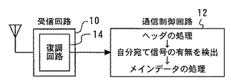
図9は、無線装置の参考例を示す図である。この無線装置は、受信信号を受信する受信回路10と、受信信号を処理する通信制御回路12とを備える。なお、通信制御回路12はソフトウェアを実行するマイコンにより構成され、受信回路10はマイコンとは別のハードウェアにより構成される。
FIG. 9 is a diagram illustrating a reference example of a wireless device. The wireless device includes a
受信回路10は、受信信号を復調データに復調する復調回路14を有する。なお、受信信号は、受信側で同期を取るためのプリアンブル信号PR、受信側で通信路を確立するためのヘッダA,B、及びメインデータで構成される。特に、間欠受信時の受信信号のヘッダは、メインデータに自分宛て信号が有るか無いかの情報を含んでいる。
The
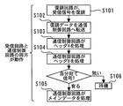
上記の無線装置の動作について、図10のフローチャートを参照しながら説明する。
まず、復調回路14は、受信信号を復調データに復調する(ステップS101)。
次に、復調回路14は、復調データを通信制御回路12へ転送する(ステップS102)。そして、通信制御回路12は、ヘッダA,Bを処理する(ステップS103,S104)。
The operation of the above wireless device will be described with reference to the flowchart of FIG.
First, the
Next, the
次に、通信制御回路12は、ヘッダA,Bの復調データを解析して、受信信号に自分宛て信号が有るか無いかを検出する。そして、自分宛て信号が有る場合、通信制御回路12は、メインデータを処理する(ステップS105)。一方、自分宛て信号が無い場合、受信回路10の電源をOFFし、通信制御回路12は、自分自身にストップ命令を出しスタンバイ状態とし、一定期間待機状態に入る(ステップS106)。待機時間は、タイマー回路によって計られ、タイムアップすると通信制御回路12に割り込み信号が供給され、通信制御回路がスタンバイ状態から起動する。
Next, the
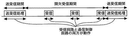
図11は、図9の無線装置の受信回路と通信制御回路の動作を説明するための図である。送受信期間では、受信回路10と通信制御回路12の両方が動作し、メインデータの受信処理や送信を行う。一方、間欠受信期間では、受信回路10と通信制御回路12の両方が動作し、受信信号に自分宛て信号が有るか無いかを検出する。自分宛て信号が有る場合は、送受信期間に移行して送受信処理を行う。自分宛て信号が無い場合は、一定時間後に再び自分宛て信号が有るか無いかを検出する。
FIG. 11 is a diagram for explaining operations of the reception circuit and the communication control circuit of the wireless device of FIG. In the transmission / reception period, both the
自分宛て信号の有無を検出する処理は複雑であるため、マイコンである通信制御回路12がソフトウェアを実行することで当該処理が行われる。そして、一般に、間欠受信期間中において、受信信号に自分宛て信号が存在しない場合の方が多い。しかし、受信動作のたびに通信制御回路12を起動させていたため、消費電力が大きかった。
Since the process of detecting the presence / absence of a signal addressed to itself is complicated, the process is performed when the
また、特許文献1の無線装置は、受信信号に自分宛て信号が無い場合に、主制御部(受信回路)の電源をオフにするが、主通信制御回路(通信制御回路)は動作を続ける。マイコンである通信制御回路は受信回路に比べて消費電流が大きいため、特許文献1の無線装置ではあまり消費電力を低減できなかった。 The wireless device disclosed in Patent Literature 1 turns off the main control unit (reception circuit) when there is no signal addressed to itself, but the main communication control circuit (communication control circuit) continues to operate. Since the communication control circuit, which is a microcomputer, consumes a larger amount of current than the receiving circuit, the wireless device of Patent Document 1 cannot reduce power consumption much.
本発明は、上述のような課題を解決するためになされたもので、その目的は消費電力を低減することができる無線装置を得るものである。 The present invention has been made to solve the above-described problems, and an object of the present invention is to obtain a wireless device capable of reducing power consumption.
本発明に係る無線装置は、受信信号を受信する受信回路と、受信信号を処理する通信制御回路とを備え、受信回路は、受信信号を復調データに復調する復調回路と、復調データを解析して、受信信号に自分宛て信号が有るか無いかを検出する検出回路と、復調データを保存するデータ保存回路とを有し、自分宛て信号が有る場合、検出回路は、通信制御回路を起動させ、保存回路に保存された復調データを通信制御回路へ転送させ、自分宛て信号が無い場合、検出回路は、通信制御回路を起動させない。本発明のその他の特徴は以下に明らかにする。 A radio apparatus according to the present invention includes a receiving circuit that receives a received signal, and a communication control circuit that processes the received signal. The receiving circuit analyzes a demodulated data by demodulating the received signal into demodulated data. And a detection circuit for detecting whether the received signal has a signal addressed to itself and a data storage circuit for storing demodulated data, and when the signal addressed to itself exists, the detection circuit activates the communication control circuit. When the demodulated data stored in the storage circuit is transferred to the communication control circuit and there is no signal addressed to itself, the detection circuit does not activate the communication control circuit. Other features of the present invention will become apparent below.
本発明により、消費電力を低減することができる。 According to the present invention, power consumption can be reduced.
実施の形態1.
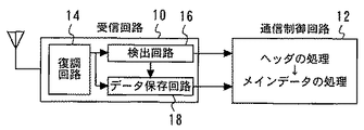
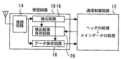
図1は、実施の形態1に係る無線装置を示す図である。この無線装置は、受信信号を受信する受信回路10と、受信信号を処理する通信制御回路12とを備える。なお、通信制御回路12はソフトウェアを実行するマイコンにより構成され、受信回路10はマイコンとは別のハードウェアにより構成される。
Embodiment 1 FIG.
1 is a diagram illustrating a radio apparatus according to Embodiment 1. FIG. The wireless device includes a
受信回路10は、復調回路14、検出回路16及びデータ保存回路18を有する。復調回路14は、受信信号を復調データに復調する。検出回路16は、復調データを解析して、受信信号に自分宛て信号が有るか無いかを検出する。データ保存回路18は、復調データを保存する。
The
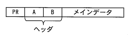
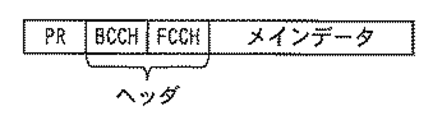
図2は、実施の形態1に係る受信信号を示す概念図である。受信信号は、受信側で同期を取るためのプリアンブル信号PR、受信側で通信路を確立するためのヘッダA,B、及びメインデータで構成される。特に、間欠受信時の受信信号のヘッダには、メインデータに自分宛て信号が有るか無いかの情報が含まれている。 FIG. 2 is a conceptual diagram showing a received signal according to the first embodiment. The reception signal includes a preamble signal PR for synchronization on the reception side, headers A and B for establishing a communication path on the reception side, and main data. In particular, the header of the reception signal at the time of intermittent reception includes information on whether or not there is a signal addressed to the main data.
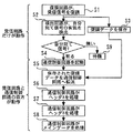
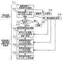
上記の無線装置の動作について、図3のフローチャートを参照しながら説明する。
まず、復調回路14は、受信信号を復調データに復調する(ステップS1)。
次に、検出回路16は、ヘッダA,Bの復調データを解析して、受信信号に自分宛て信号が有るか無いかを検出する(ステップS2)。データ保存回路18は、検出回路16が復調データを解析している間、復調データを保存する(ステップS3)。
The operation of the wireless device will be described with reference to the flowchart of FIG.
First, the
Next, the
自分宛て信号が有る場合、検出回路16は、通信制御回路12をスタンバイ状態から起動させ(ステップS4)、データ保存回路18に保存された復調データを通信制御回路12へ転送させる(ステップS5)。そして、通信制御回路12は、ヘッダA,B及びメインデータを処理する(ステップS6〜S8)。
When there is a signal addressed to itself, the
一方、自分宛て信号が無い場合、検出回路16は通信制御回路12をスタンバイ状態のままで起動させず、一定期間待機状態に入る(ステップS9)。データ保存回路18に保存した復調データは廃棄されるか、次回上書きされる。
On the other hand, when there is no signal addressed to itself, the
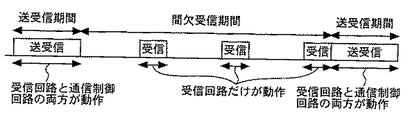
図4は、実施の形態1に係る無線装置の受信回路と通信制御回路の動作を説明するための図である。送受信期間では、受信回路10と通信制御回路12の両方が動作し、メインデータの受信処理や送信を行う。一方、間欠受信期間では、所定のタイミングで受信回路10のみ動作し、受信信号に自分宛て信号が有るか無いかを検出する。自分宛て信号が有る場合は、送受信期間に移行して送受信処理を行う。自分宛て信号が無い場合は、一定時間後に再び受信信号に自分宛て信号が有るか無いかを検出する。
FIG. 4 is a diagram for explaining operations of the reception circuit and the communication control circuit of the wireless device according to the first embodiment. In the transmission / reception period, both the
なお、通信制御回路12をスタンバイ状態から起動させる場合、一般的には割り込み信号を通信制御回路12に供給する。また、送受信期間から間欠受信期間に移行する場合、通信制御回路12は自分自身に対してストップ命令を出してスタンバイ状態となり、受信回路10の電源をOFFにする。
When the
以上説明したように、自分宛て信号の有無を検出する機能を受信回路10に持たせ、自分宛て信号が有る場合にのみ通信制御回路12を起動させるため、消費電力を低減することができる。また、本実施の形態を採用しても、通信制御回路12の処理内容は、通常の仕様から大きく変更する必要がない。
As described above, since the
実施の形態2.
図5は、実施の形態2に係る無線装置を示す図である。受信回路10は、検出回路16の検出結果を保存する検出結果保存回路20を更に有する。その他の構成は実施の形態1の構成と同様である。
FIG. 5 is a diagram illustrating a radio apparatus according to the second embodiment. The receiving
本実施の形態に係る無線装置の動作について、図6のフローチャートを参照しながら説明する。
まず、復調回路14は、受信信号を復調データに復調する(ステップS11)。
次に、検出回路16は、ヘッダA,Bの復調データを解析して、受信信号に自分宛て信号が有るか無いかを検出する(ステップS12)。データ保存回路18は、検出回路16が復調データを解析している間、復調データを保存する(ステップS13)。検出結果保存回路20は、検出回路16の検出結果を保存する(ステップS14)。
The operation of the radio apparatus according to this embodiment will be described with reference to the flowchart of FIG.
First, the
Next, the
自分宛て信号が有る場合、検出回路16は、通信制御回路12をスタンバイ状態から起動させ(ステップS15)、データ保存回路18に保存された復調データを通信制御回路12へ転送させる(ステップS16)。そして、通信制御回路12は、ヘッダA,Bを処理する(ステップS17,S18)。この際に、通信制御回路12は、必要に応じて検出結果保存回路20に保存された検出結果を参照する。さらに、通信制御回路12は、メインデータを処理する(ステップS19)。
If there is a signal addressed to itself, the
一方、自分宛て信号が無い場合、検出回路16は通信制御回路12をスタンバイ状態のままで起動させず、一定期間待機状態に入る(ステップS20)。データ保存回路18に保存した復調データは廃棄されるか、次回上書きされる。
On the other hand, when there is no signal addressed to itself, the
本実施の形態により、実施の形態1と同様の効果を得ることができる。また、一部のデータについて、従来は自分宛て信号が無い場合でも通信制御回路12が処理していた。これに対し、本実施の形態では、検出回路16の検出結果を検出結果保存回路20で保存し、通信制御回路12が起動した際に検出結果保存回路20を参照して処理を行うことで、自分宛て信号が無い場合に通信制御回路12を起動させたのと等価な処理を行うことができる。
According to the present embodiment, the same effect as in the first embodiment can be obtained. Further, conventionally, the
実施の形態3.
図7は、実施の形態3に係る受信信号を示す概念図である。受信信号は、受信側で同期を取るためのプリアンブル信号PR、受信側で通信路を確立するためのヘッダであるBCCH,FCCH、及びメインデータで構成される。BCCHは、基地局からの報知用情報信号である。一般的に、無線装置は、まずBCCHを受信して本システムの信号であることを認識する。また、FCCHは、周波数チャネルに関する情報信号であり、メインデータに自分宛て信号が有るか無いかや、メインデータのどこに自分宛て信号が存在するかといった情報を含んでいる。
Embodiment 3 FIG.
FIG. 7 is a conceptual diagram showing a received signal according to the third embodiment. The received signal includes a preamble signal PR for synchronization on the receiving side, BCCH and FCCH which are headers for establishing a communication path on the receiving side, and main data. BCCH is a broadcast information signal from the base station. In general, a wireless device first receives a BCCH and recognizes that it is a signal of this system. The FCCH is an information signal related to the frequency channel, and includes information such as whether or not the main data has a signal addressed to itself and where in the main data the signal addressed to itself exists.
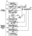
本実施の形態に係る無線装置の動作について、図8のフローチャートを参照しながら説明する。なお、無線装置の構造は実施の形態2の構造と同様である。
まず、復調回路14は、受信信号を復調データに復調する(ステップS21)。
次に、検出回路16は、ヘッダであるBCCHの復調データを解析して、BCCHのCRCチェックやIDチェックを行い、受信信号が当システムの信号であることを確認する(ステップS22)。データ保存回路18は、検出回路16が復調データを解析している間、復調データを保存する(ステップS23)。検出結果保存回路20は、CRCチェックやIDチェックの結果を保存する(ステップS24)。
The operation of the radio apparatus according to this embodiment will be described with reference to the flowchart of FIG. The structure of the wireless device is the same as that of the second embodiment.
First, the
Next, the
次に、検出回路16は、ヘッダであるFCCHの復調データを解析して、受信信号に自分宛て信号が有るか無いかを検出する(ステップS25)。検出結果保存回路20は、検出回路16の検出結果を保存する(ステップS24)。なお、BCCHのCRCチェックでNGになった場合も自分宛て信号が無いと判断される。
Next, the
自分宛て信号が有る場合、検出回路16は、通信制御回路12をスタンバイ状態から起動させ(ステップS26)、データ保存回路18に保存された復調データを通信制御回路12へ転送させる(ステップS27)。そして、通信制御回路12は、BCCH,FCCHを処理する(ステップS28,S29)。この際に、通信制御回路12は、必要に応じて検出結果保存回路20に保存された検出結果を参照する。さらに、通信制御回路12は、メインデータを処理する(ステップS30)。
If there is a signal addressed to itself, the
一方、自分宛て信号が無い場合、検出回路16は通信制御回路12をスタンバイ状態のままで起動させず、一定期間待機状態に入る(ステップS31)。データ保存回路18に保存した復調データは廃棄されるか、次回上書きされる。
On the other hand, when there is no signal addressed to itself, the
本実施の形態により、実施の形態1と同様の効果を得ることができる。また、「CRCチェックがNG」などの一部のデータについて、従来は自分宛て信号が無い場合でも通信制御回路12が処理していた。これに対し、本実施の形態では、検出回路16の検出結果を検出結果保存回路20で保存し、通信制御回路12が起動した際に検出結果保存回路20を参照することで、自分宛て信号が無い場合に通信制御回路12を起動させたのと等価な処理を行うことができる。
According to the present embodiment, the same effect as in the first embodiment can be obtained. Further, the
10 受信回路
12 通信制御回路
14 復調回路
16 検出回路
18 データ保存回路
20 検出結果保存回路
DESCRIPTION OF
Claims (2)
前記受信信号を処理する通信制御回路とを備え、
前記受信回路は、
前記受信信号を復調データに復調する復調回路と、
前記復調データを解析して、前記受信信号に自分宛て信号が有るか無いかを検出する検出回路と、
前記復調データを保存するデータ保存回路とを有し、
前記自分宛て信号が有る場合、前記検出回路は、前記通信制御回路を起動させ、前記保存回路に保存された前記復調データを前記通信制御回路へ転送させ、
前記自分宛て信号が無い場合、前記検出回路は、前記通信制御回路を起動させないことを特徴とする無線装置。 A receiving circuit for receiving a received signal;
A communication control circuit for processing the received signal,
The receiving circuit is
A demodulation circuit for demodulating the received signal into demodulated data;
A detection circuit that analyzes the demodulated data and detects whether the received signal has a signal addressed to itself;
A data storage circuit for storing the demodulated data,
When there is a signal addressed to itself, the detection circuit activates the communication control circuit, causes the demodulation data stored in the storage circuit to be transferred to the communication control circuit,
The wireless device according to claim 1, wherein when there is no signal addressed to itself, the detection circuit does not activate the communication control circuit.
前記自分宛て信号が有る場合、前記通信制御回路は、前記検出結果保存回路に保存された前記検出結果を参照することを特徴とする請求項1に記載の無線装置。 The receiving circuit further includes a detection result storage circuit that stores the detection result of the detection circuit,
The radio apparatus according to claim 1, wherein when there is a signal addressed to itself, the communication control circuit refers to the detection result stored in the detection result storage circuit.
Priority Applications (1)
| Application Number | Priority Date | Filing Date | Title |
|---|---|---|---|
| JP2008074271A JP4673902B2 (en) | 2008-03-21 | 2008-03-21 | Wireless device |
Applications Claiming Priority (1)
| Application Number | Priority Date | Filing Date | Title |
|---|---|---|---|
| JP2008074271A JP4673902B2 (en) | 2008-03-21 | 2008-03-21 | Wireless device |
Publications (2)
| Publication Number | Publication Date |
|---|---|
| JP2009232103A true JP2009232103A (en) | 2009-10-08 |
| JP4673902B2 JP4673902B2 (en) | 2011-04-20 |
Family
ID=41247021
Family Applications (1)
| Application Number | Title | Priority Date | Filing Date |
|---|---|---|---|
| JP2008074271A Active JP4673902B2 (en) | 2008-03-21 | 2008-03-21 | Wireless device |
Country Status (1)
| Country | Link |
|---|---|
| JP (1) | JP4673902B2 (en) |
Cited By (3)
| Publication number | Priority date | Publication date | Assignee | Title |
|---|---|---|---|---|
| WO2012114968A1 (en) * | 2011-02-23 | 2012-08-30 | 株式会社国際電気通信基礎技術研究所 | Wireless base station and wireless communication system using same |
| WO2012114969A1 (en) * | 2011-02-23 | 2012-08-30 | 株式会社国際電気通信基礎技術研究所 | Terminal device, wireless base station wirelessly communicating with same, and wireless communication system using terminal device and wireless base station |
| JP2013009430A (en) * | 2012-09-27 | 2013-01-10 | Advanced Telecommunication Research Institute International | TERMINAL DEVICE, WIRELESS BASE STATION FOR WIRELESS COMMUNICATION WITH THE SAME AND WIRELESS COMMUNICATION SYSTEM USING THE SAME |
Citations (3)
| Publication number | Priority date | Publication date | Assignee | Title |
|---|---|---|---|---|
| JPH07264118A (en) * | 1994-03-23 | 1995-10-13 | Mitsubishi Electric Corp | Device and method for intermittent reception of received data |
| JP2001069072A (en) * | 1999-07-20 | 2001-03-16 | Motorola Inc | Method and system for reducing power consumption of communication device |
| JP2003209616A (en) * | 2002-01-15 | 2003-07-25 | Fujitsu Ltd | Semiconductor device and portable terminal device |
-
2008
- 2008-03-21 JP JP2008074271A patent/JP4673902B2/en active Active
Patent Citations (3)
| Publication number | Priority date | Publication date | Assignee | Title |
|---|---|---|---|---|
| JPH07264118A (en) * | 1994-03-23 | 1995-10-13 | Mitsubishi Electric Corp | Device and method for intermittent reception of received data |
| JP2001069072A (en) * | 1999-07-20 | 2001-03-16 | Motorola Inc | Method and system for reducing power consumption of communication device |
| JP2003209616A (en) * | 2002-01-15 | 2003-07-25 | Fujitsu Ltd | Semiconductor device and portable terminal device |
Cited By (8)
| Publication number | Priority date | Publication date | Assignee | Title |
|---|---|---|---|---|
| WO2012114968A1 (en) * | 2011-02-23 | 2012-08-30 | 株式会社国際電気通信基礎技術研究所 | Wireless base station and wireless communication system using same |
| WO2012114969A1 (en) * | 2011-02-23 | 2012-08-30 | 株式会社国際電気通信基礎技術研究所 | Terminal device, wireless base station wirelessly communicating with same, and wireless communication system using terminal device and wireless base station |
| JP2012175516A (en) * | 2011-02-23 | 2012-09-10 | Advanced Telecommunication Research Institute International | Radio base station and radio communication system using the same |
| JP2012175544A (en) * | 2011-02-23 | 2012-09-10 | Advanced Telecommunication Research Institute International | Terminal device, radio base station communicating with it, and radio communication system using them |
| US9374784B2 (en) | 2011-02-23 | 2016-06-21 | Advanced Telecommunications Research Institute International | Terminal device, wireless base station wirelessly communicating with the same, and wireless communication system using terminal device and wireless base station |
| US9521613B2 (en) | 2011-02-23 | 2016-12-13 | Advanced Telecommunications Research Institute International | Wireless base station and wireless communication system using the same |
| US9867126B2 (en) | 2011-02-23 | 2018-01-09 | Advanced Telecommunications Research Institute International | Wireless base station and wireless communication systems using the same |
| JP2013009430A (en) * | 2012-09-27 | 2013-01-10 | Advanced Telecommunication Research Institute International | TERMINAL DEVICE, WIRELESS BASE STATION FOR WIRELESS COMMUNICATION WITH THE SAME AND WIRELESS COMMUNICATION SYSTEM USING THE SAME |
Also Published As
| Publication number | Publication date |
|---|---|
| JP4673902B2 (en) | 2011-04-20 |
Similar Documents
| Publication | Publication Date | Title |
|---|---|---|
| US7236213B2 (en) | Receiving apparatus and receiving method of reduced power consumption for receiving a broadcast transmission | |
| JP2012142877A (en) | Radio communication apparatus | |
| AU2003240630A1 (en) | Method and apparatus for minimizing time of reception during paging | |
| US6088576A (en) | Receiver providing signal reception in power-off state | |
| JP4673902B2 (en) | Wireless device | |
| JP2009152999A (en) | TMCC signal receiver | |
| CN101019426B (en) | Device and method for controlling battery power in digital multimedia broadcasting terminal | |
| US9025506B2 (en) | Wireless communication device, wireless communication system and wireless communication method | |
| JP4620414B2 (en) | Wireless communication terminal device and program | |
| EP1677424B1 (en) | Apparatus and method for reducing electric power consumption in mobile communication terminal | |
| JP4690248B2 (en) | Digital broadcast receiving apparatus and receiving method | |
| JP2006050396A5 (en) | ||
| JP4998206B2 (en) | Wireless communication apparatus and wireless communication method | |
| JP2006086760A (en) | Time division multiplex synchronization apparatus and synchronization method in time division multiplex communication | |
| JP2004336330A (en) | Mobile terminal device | |
| JP4279708B2 (en) | PHS terminal apparatus and PHS data receiving method | |
| JP2826522B2 (en) | Wireless mobile station | |
| JP2003158691A (en) | Portable digital broadcast receiver | |
| JP5028229B2 (en) | TMCC signal receiver | |
| JP4997071B2 (en) | TMCC signal receiver | |
| JP2005109911A (en) | Digital broadcast receiver | |
| CN115866755B (en) | Paging detection method, device, equipment and medium | |
| JP4646938B2 (en) | Method for controlling wireless communication terminal device | |
| JP4660023B2 (en) | Wireless communication device | |
| JP2005333351A (en) | Receiver |
Legal Events
| Date | Code | Title | Description |
|---|---|---|---|
| A977 | Report on retrieval |
Free format text: JAPANESE INTERMEDIATE CODE: A971007 Effective date: 20100903 |
|
| A131 | Notification of reasons for refusal |
Free format text: JAPANESE INTERMEDIATE CODE: A131 Effective date: 20100921 |
|
| A521 | Request for written amendment filed |
Free format text: JAPANESE INTERMEDIATE CODE: A523 Effective date: 20101116 |
|
| TRDD | Decision of grant or rejection written | ||
| A01 | Written decision to grant a patent or to grant a registration (utility model) |
Free format text: JAPANESE INTERMEDIATE CODE: A01 Effective date: 20110118 |
|
| A01 | Written decision to grant a patent or to grant a registration (utility model) |
Free format text: JAPANESE INTERMEDIATE CODE: A01 |
|
| A61 | First payment of annual fees (during grant procedure) |
Free format text: JAPANESE INTERMEDIATE CODE: A61 Effective date: 20110121 |
|
| R150 | Certificate of patent or registration of utility model |
Ref document number: 4673902 Country of ref document: JP Free format text: JAPANESE INTERMEDIATE CODE: R150 |
|
| FPAY | Renewal fee payment (event date is renewal date of database) |
Free format text: PAYMENT UNTIL: 20140128 Year of fee payment: 3 |
|
| R250 | Receipt of annual fees |
Free format text: JAPANESE INTERMEDIATE CODE: R250 |
|
| S531 | Written request for registration of change of domicile |
Free format text: JAPANESE INTERMEDIATE CODE: R313531 |
|
| R350 | Written notification of registration of transfer |
Free format text: JAPANESE INTERMEDIATE CODE: R350 |
|
| R250 | Receipt of annual fees |
Free format text: JAPANESE INTERMEDIATE CODE: R250 |
|
| R250 | Receipt of annual fees |
Free format text: JAPANESE INTERMEDIATE CODE: R250 |
|
| R250 | Receipt of annual fees |
Free format text: JAPANESE INTERMEDIATE CODE: R250 |
|
| S111 | Request for change of ownership or part of ownership |
Free format text: JAPANESE INTERMEDIATE CODE: R313117 |
|
| R350 | Written notification of registration of transfer |
Free format text: JAPANESE INTERMEDIATE CODE: R350 |
|
| S533 | Written request for registration of change of name |
Free format text: JAPANESE INTERMEDIATE CODE: R313533 |
|
| R360 | Written notification for declining of transfer of rights |
Free format text: JAPANESE INTERMEDIATE CODE: R360 |
|
| R360 | Written notification for declining of transfer of rights |
Free format text: JAPANESE INTERMEDIATE CODE: R360 |
|
| R371 | Transfer withdrawn |
Free format text: JAPANESE INTERMEDIATE CODE: R371 |
|
| S533 | Written request for registration of change of name |
Free format text: JAPANESE INTERMEDIATE CODE: R313533 |
|
| R350 | Written notification of registration of transfer |
Free format text: JAPANESE INTERMEDIATE CODE: R350 |