JP2009220439A - Uneven-thickness resin sheet and manufacturing method of uneven-thickness resin sheet - Google Patents
Uneven-thickness resin sheet and manufacturing method of uneven-thickness resin sheet Download PDFInfo
- Publication number
- JP2009220439A JP2009220439A JP2008068206A JP2008068206A JP2009220439A JP 2009220439 A JP2009220439 A JP 2009220439A JP 2008068206 A JP2008068206 A JP 2008068206A JP 2008068206 A JP2008068206 A JP 2008068206A JP 2009220439 A JP2009220439 A JP 2009220439A
- Authority
- JP
- Japan
- Prior art keywords
- resin sheet
- uneven thickness
- roller
- uneven
- thickness
- Prior art date
- Legal status (The legal status is an assumption and is not a legal conclusion. Google has not performed a legal analysis and makes no representation as to the accuracy of the status listed.)
- Pending
Links
Images

Landscapes
- Extrusion Moulding Of Plastics Or The Like (AREA)
Abstract
【課題】膜厚に偏りがある偏肉樹脂シートにおいて、経時的な反りを防ぎ、良好な品質の偏肉樹脂シートを製造する偏肉樹脂シートの製造方法を提供することを目的とする。
【解決手段】押出成形法により成形され、膜厚に偏りがあるポリメチルメタクリレート樹脂の偏肉樹脂シートにおいて、幅方向に関し、膜厚が最も大きい最膜厚部52と膜厚が最も小さい最膜薄部54との膜厚差は、0.5mm以上であって5mm以下であり、幅方向に関する複屈折量の差は、20nm以上であって110nm以下である。このような特性を有する偏肉樹脂シートSは、経時的な反りを効果的に低減することができる。
【選択図】図7An object of the present invention is to provide a method of manufacturing an uneven thickness resin sheet that prevents warping over time in an uneven thickness resin sheet having an uneven thickness, and manufactures an uneven thickness resin sheet of good quality.
In an uneven thickness resin sheet of polymethylmethacrylate resin formed by an extrusion molding method and having an uneven film thickness, the largest film thickness portion 52 having the largest film thickness and the smallest film having the smallest film thickness in the width direction. The difference in film thickness from the thin part 54 is 0.5 mm or more and 5 mm or less, and the difference in birefringence amount in the width direction is 20 nm or more and 110 nm or less. The uneven thickness resin sheet S having such characteristics can effectively reduce warping over time.
[Selection] Figure 7
Description
本発明は膜厚に偏りがある偏肉樹脂シートおよび偏肉樹脂シートの製造方法に係り、例えば液晶表示装置のバックライトの導光板や、装飾・表示・照明用ディスプレイの導光板などの光学シートとして使用される偏肉樹脂シートに関する。 BACKGROUND OF THE INVENTION 1. Field of the Invention The present invention relates to an uneven thickness resin sheet having an uneven film thickness and a manufacturing method of the uneven thickness resin sheet, for example, an optical sheet such as a light guide plate for a backlight of a liquid crystal display device and a light guide plate for a display for decoration, display, and illumination. It is related with the uneven thickness resin sheet used as.
液晶表示装置のバックライトや装飾・表示・照明用のディスプレイ装置には、光源からの光を導いて面発光する導光板が使用されており、例えば液晶表示装置には、液晶パネルの裏面側から導光板を介して光を照射するバックライトが設けられている。 A light guide plate that guides light from a light source and emits a surface light is used in a backlight of a liquid crystal display device and a display device for decoration, display, and illumination. For example, a liquid crystal display device has a light guide plate from the back side of a liquid crystal panel. A backlight for irradiating light through a light guide plate is provided.
このような導光板のうち大画面液晶テレビなどの大型装置に用いられる導光板は、現行の設備や技術を背景に、押出成形法により製造されることが一般的である。この押出成形法では、通常、均一な膜厚を有する溶融状態の樹脂シートがダイ(Tダイ等)から押し出されて冷却ローラー(ポリシングローラー)により冷却される。当該樹脂シートは、その後、引取ローラーによる引っ張り搬送中に空冷され、所定形状に切断された後に、積み重ねられて保管される。 Among such light guide plates, a light guide plate used for a large apparatus such as a large-screen liquid crystal television is generally manufactured by an extrusion molding method against the background of current equipment and technology. In this extrusion molding method, a molten resin sheet having a uniform film thickness is usually extruded from a die (T-die or the like) and cooled by a cooling roller (polishing roller). Thereafter, the resin sheet is air-cooled during pulling conveyance by the take-up roller, cut into a predetermined shape, and then stacked and stored.
この押出成形法によって作られる樹脂シートのうち、均一な膜厚を有する平らな樹脂シートでは、二次加工の際に問題となりうる反り等の寸法変化を抑制するために、押出成形時にもたらされる内部歪み(内部応力)を低減することが好ましく、そのような内部歪みを低減する方法がいくつか提案されている。 Among the resin sheets produced by this extrusion method, the flat resin sheet having a uniform film thickness has an internal effect brought about during extrusion molding in order to suppress dimensional changes such as warpage that can cause problems during secondary processing. It is preferable to reduce strain (internal stress), and several methods for reducing such internal strain have been proposed.
たとえば特許文献1には、ポリシングロールまたはその近傍において、樹脂シートの両端部を加熱したり或いは樹脂シートの中央部を冷却する方法を開示する。この方法によれば、引取ロールの周速度がポリシングロールの周速度と等速に調整されて樹脂シートを無張力状態に保持した場合に発生する樹脂シート端部の波打ち(エッジウェーブ)を改善することができる。 For example, Patent Document 1 discloses a method of heating both ends of a resin sheet or cooling a central portion of a resin sheet at or near a polishing roll. According to this method, the peripheral speed of the take-up roll is adjusted to be equal to the peripheral speed of the polishing roll to improve the undulation (edge wave) at the end of the resin sheet that occurs when the resin sheet is held in a tensionless state. be able to.
また特許文献2には、ポリシングロールの後段の搬送部において、樹脂シートを上下からヒータで加熱してシート上面と下面の温度を均一にすることで、温度差に起因する内部歪み及び反りを低減する方法を開示する。 Further, in Patent Document 2, internal distortion and warpage due to a temperature difference are reduced by heating the resin sheet from above and below with a heater in the conveyance unit at the subsequent stage of the polishing roll to make the temperature of the upper and lower surfaces of the sheet uniform. A method is disclosed.
また特許文献3および特許文献4には、樹脂が最初に密着する冷却ローラーと最後に密着する冷却ローラーとの間で負の周速差をもたせることにより、内部歪みを抑制する方法が開示されている。また、特許文献5も、樹脂が最後に密着する冷却ローラーと最後から2番目に密着する冷却ローラーとの間、および引取ローラーと第2ローラーとの間で、負の周速差をもたせる方法が開示されている。 Patent Document 3 and Patent Document 4 disclose a method of suppressing internal distortion by providing a negative peripheral speed difference between the cooling roller to which the resin first adheres and the cooling roller to which the resin first adheres. Yes. Patent Document 5 also discloses a method in which a negative peripheral speed difference is provided between the cooling roller with which the resin comes into close contact with the cooling roller with which the resin comes into contact with the last, and between the take-up roller and the second roller. It is disclosed.
また特許文献6には、冷却ローラーの温度を調節し且つ押し出されたシートを加熱することにより、樹脂シートの温度を高くした後に緩やかに徐冷して、内部応力を緩和する方法が開示されている。 Patent Document 6 discloses a method of relaxing internal stress by slowly cooling after increasing the temperature of the resin sheet by adjusting the temperature of the cooling roller and heating the extruded sheet. Yes.
また、特許文献7には最後の冷却ローラーと最初のガイドローラーとの間でシートに撓みをもたせることにより、内部応力を緩和する方法が開示されている。 Patent Document 7 discloses a method of relaxing internal stress by causing a sheet to bend between the last cooling roller and the first guide roller.
なお、特許文献8では、型ローラとニップローラとの共通接線に対してダイの吐出口が型ローラ側に配置される樹脂シートの製造装置が教示されている。
しかしながら、上記の特許文献1〜7で提案されている方法は、いずれも均一な膜厚を有する樹脂シートを対象としており、均一な膜厚を持たない偏肉樹脂シートに対しては、必ずしも好適な技術とは言えない。 However, the methods proposed in the above Patent Documents 1 to 7 are all intended for resin sheets having a uniform film thickness, and are not necessarily suitable for uneven thickness resin sheets having no uniform film thickness. It's not a good technology.
また、幅方向の厚みの分布が大きい偏肉樹脂シートを押出成形法で成形する場合に、幅方向に関する内部歪みを一様に小さくすると、偏肉樹脂シートの切断後に経時で大きな反りが発生してしまい、所望のシート形状を長時間にわたって維持することが困難である。このような反りは、変形を招いて複数の偏肉樹脂シートを積み重ねる等して保管することが難しくなり、多数の偏肉樹脂シートを連続的に生産するのに支障をきたす等、ハンドリングの面でも不都合がある。 In addition, when an uneven thickness resin sheet having a large thickness distribution in the width direction is formed by an extrusion molding method, if the internal strain in the width direction is uniformly reduced, a large warp will occur over time after cutting the uneven thickness resin sheet. Therefore, it is difficult to maintain a desired sheet shape for a long time. Such warping causes deformation and makes it difficult to store a plurality of uneven thickness resin sheets by stacking them, and hinders continuous production of a large number of uneven thickness resin sheets. But there are inconveniences.
本発明は、上述の事情に鑑みてなされたものであり、膜厚が一様ではない偏肉樹脂シートの経時的な反りを低減して、形状安定性に優れた偏肉樹脂シートおよび偏肉樹脂シートの製造方法を提供することを目的とする。 The present invention has been made in view of the above-described circumstances, and reduces the warpage with time of an uneven thickness resin sheet having a non-uniform film thickness. It aims at providing the manufacturing method of a resin sheet.
本発明の一態様は、幅方向に関して膜厚に偏りがあるポリメチルメタクリレート樹脂の偏肉樹脂シートであって、前記幅方向に関して、膜厚が最も大きい最膜厚部と膜厚が最も小さい最膜薄部との膜厚差は、0.5mm以上であって5mm以下であり、前記幅方向に関して、複屈折量の差が20nm以上であって110nm以下であることを特徴とする偏肉樹脂シートに関する。 One aspect of the present invention is a polymethylmethacrylate resin uneven thickness resin sheet having a biased film thickness with respect to the width direction, wherein the largest film thickness portion with the largest film thickness and the smallest film thickness with respect to the width direction. The thickness difference between the thin film portion is 0.5 mm or more and 5 mm or less, and the birefringence difference is 20 nm or more and 110 nm or less with respect to the width direction. Regarding the sheet.
本態様の偏肉樹脂シートは、幅方向に関する複屈折量の差(分布)が20nm以上であって110nm以下に調整されており、経時的な反りを防ぐ観点からは適度な歪みが偏肉樹脂シートに付与されている。なお、偏肉樹脂シートの複屈折量は、用途に応じて適宜調整され、許容可能な複屈折量(歪み度)および経時的な反り量のバランスによって調整されることが望ましい。 The uneven thickness resin sheet of this embodiment has a birefringence difference (distribution) in the width direction of 20 nm or more and is adjusted to 110 nm or less. It is given to the sheet. Note that the birefringence amount of the uneven thickness resin sheet is appropriately adjusted according to the application, and is preferably adjusted by the balance between the allowable birefringence amount (distortion degree) and the warpage amount with time.
なお、上記の複屈折量の差は、30nm以上であって110nm以下である場合により効果的に偏肉樹脂シートの反りを低減することができ、50nm以上であって110nm以下である場合に更に効果的に偏肉樹脂シートの反りを低減することができる。 In addition, when the difference in the amount of birefringence is 30 nm or more and 110 nm or less, warpage of the uneven thickness resin sheet can be reduced more effectively, and when the difference is 50 nm or more and 110 nm or less. Warpage of the uneven thickness resin sheet can be effectively reduced.
前記偏肉樹脂シートは、押出成形法により成形されてもよい。幅方向に関して膜厚に偏りがある偏肉樹脂シートは、押出成形法により製造されることが多いが、押出成形法で製造された偏肉樹脂シートは経時的な反りが生じやすい。しかしながら、本発明の上記態様によれば、押出成形法で製造した偏肉樹脂シートであっても、経時的な反りを効果的に抑制することができる。 The uneven thickness resin sheet may be formed by an extrusion method. An uneven thickness resin sheet having an uneven thickness in the width direction is often manufactured by an extrusion method, but an uneven thickness resin sheet manufactured by an extrusion method tends to warp with time. However, according to the said aspect of this invention, even if it is the uneven thickness resin sheet manufactured by the extrusion molding method, the time-dependent curvature can be suppressed effectively.
前記偏肉樹脂シートは、前記幅方向に関して、前記最膜薄部を複数含み、前記複数の最膜薄部は、200mm以上のピッチを有していてもよい。ピッチが200mmより短い断面形状の偏肉樹脂シートの場合は、押出成形法で製造する場合には、いわゆるバンク(図4の符号44参照)において溶融樹脂の流動により配向歪みが生じてしまい、複屈折量を制御することが困難となる。
The uneven thickness resin sheet may include a plurality of the thinnest film parts in the width direction, and the plurality of thinnest film parts may have a pitch of 200 mm or more. In the case of an uneven-thickness resin sheet having a cross-sectional shape with a pitch shorter than 200 mm, when it is manufactured by an extrusion molding method, orientation distortion occurs due to the flow of the molten resin in a so-called bank (see
このように最膜薄部のピッチが比較的長い場合に、偏肉樹脂シートに反りが生じやすいが、本発明の上記態様によれば、そのような偏肉樹脂シートであっても反りを効果的に抑制することができる。 Thus, when the pitch of the thinnest part is relatively long, the uneven thickness resin sheet is likely to warp. However, according to the above aspect of the present invention, the warpage is effective even with such an uneven thickness resin sheet. Can be suppressed.
前記最膜薄部の複屈折量と前記最膜厚部の複屈折量との差が20nm以上であって110nm以下であることが望ましい。 It is desirable that the difference between the birefringence amount of the thinnest film portion and the birefringence amount of the thickest film portion is 20 nm or more and 110 nm or less.
最膜薄部と最膜厚部との間で複屈折量の差が最大となるように偏肉樹脂シートを加工することにより、上記の特性を有する偏肉樹脂シートを容易に製造することができる。 By processing the thick resin sheet so that the difference in birefringence between the thinnest film part and the thickest film part is maximized, it is possible to easily manufacture the thick resin sheet having the above characteristics. it can.
本発明の他の態様は、上記の偏肉樹脂シートにアニール処理を施すことを特徴とする偏肉樹脂シートの製造方法に関する。 Another aspect of the present invention relates to a method for producing an uneven thickness resin sheet, wherein the uneven thickness resin sheet is annealed.
二次加工の際に生じる反り等が問題となる場合は、上記の偏肉樹脂シートをアニール処理することで、反りを低減することができる。アニール処理の際に変形や反りが生じる場合は、保持具などで形状を矯正してアニールをすることで、良好な形状の樹脂シートを得ることができる。 When warpage or the like generated during secondary processing becomes a problem, the warpage can be reduced by annealing the above-described uneven thickness resin sheet. When deformation or warpage occurs during the annealing treatment, a resin sheet having a good shape can be obtained by correcting the shape with a holder or the like and performing annealing.
本発明によれば、幅方向に関する複屈折量の差が20nm以上であって110nm以下に調整されているため、適度な歪みが偏肉樹脂シートに付与されており、経時的な反りを効果的に低減することができる。 According to the present invention, since the difference in the birefringence amount in the width direction is adjusted to 20 nm or more and 110 nm or less, moderate distortion is imparted to the uneven thickness resin sheet, and warping with time is effective. Can be reduced.
以下、図面を参照して本発明の実施形態について説明する。 Hereinafter, embodiments of the present invention will be described with reference to the drawings.
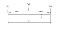
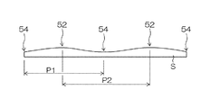
図1および図2は、本実施形態において製造される蒲鉾形状の偏肉樹脂シートSの幅方向に関する断面を例示する図である。本実施形態では、シート幅方向に関して膜厚に偏りのある偏肉樹脂シートを成形対象としており、例えば図1に示すように、最も膜厚の大きな最膜厚部52がシート幅方向の中央部に設けられ、最も膜厚の薄い最膜薄部54がシート幅方向の両端部に設けられる偏肉樹脂シートSを製造することができる。また、図2に示すように、図1に示す樹脂シートをシート幅方向に複数(2個)並べたような断面形状を有する樹脂シートSを製造することも可能である。図2に示す樹脂シートSは、最膜厚部52および最膜薄部54が周期的に配される断面構造を有し、シート幅方向に関して最膜薄部54および最膜厚部52が交互に出現する構造となっている。
1 and 2 are views illustrating a cross section in the width direction of a bowl-shaped uneven thickness resin sheet S manufactured in this embodiment. In the present embodiment, an uneven thickness resin sheet having an uneven thickness in the sheet width direction is a molding target. For example, as shown in FIG. 1, the thickest
このような断面形状を有する偏肉樹脂シートを製造する場合には、樹脂シートSのシート幅が大きくなるほど、バンクが乱れやすく、樹脂シートSを良好な面状に成形しながら反りを防ぐということが難しくなる。また、最膜薄部54のピッチP1および最膜厚部52のピッチP2が大きくなるほど、バンクが乱れやすく、樹脂シートSを良好な面状に成形しながら反りを防ぐということが難しくなる。また、樹脂シートSのシート幅方向に関する膜厚差、すなわち最膜厚部52と最膜薄部54との膜厚差が大きくなるほど、バンクが乱れやすく、樹脂シートSを良好な面状に成形しながら反りを防ぐということが難しくなる。しかしながら、以下に述べる本実施形態によれば、乾燥状態において、シート幅が200mm以上750mm以下(とりわけ450mm以上750mm以下)、最膜薄部54のピッチP1および最膜厚部52のピッチP2が200mm以上、そして最膜厚部52の膜厚Dmaxと最膜薄部54の膜厚Dminとの差(|Dmax−Dmin|)が0.5mm以上5mm以下(より好ましくは0.5mm以上3mm以下)である偏肉樹脂シートSを良好な状態で成形することが可能である。
When manufacturing an uneven thickness resin sheet having such a cross-sectional shape, the larger the sheet width of the resin sheet S, the more easily the bank is disturbed, which prevents warping while forming the resin sheet S into a good surface shape. Becomes difficult. Further, the larger the pitch P1 of the
なお、膜薄部(最膜薄部)54のピッチP1および膜厚部(最膜厚部)52のピッチP2は、1000mm以下であってもよく、このようなピッチを有する樹脂シートSであればディスプレイ等の幅広い用途に使用することが可能である。 The pitch P1 of the thin film portion (most thin film portion) 54 and the pitch P2 of the film thickness portion (maximum film thickness portion) 52 may be 1000 mm or less, and the resin sheet S having such a pitch may be used. It can be used for a wide range of applications such as displays.
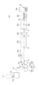
図3は、偏肉樹脂シートを製造する偏肉樹脂シート製造装置の一例を示す図である。図3に示す偏肉樹脂シート製造装置10では、原料調製装置11、押出機12、ダイ16、成形冷却ローラー部17、熱処理ゾーン24、冷却ゾーン26、面状検査機28、ラミネート機30、切断機32、及びスタッカー34が、上流側から下流側へ順次設けられている。
FIG. 3 is a diagram illustrating an example of an uneven thickness resin sheet manufacturing apparatus for manufacturing an uneven thickness resin sheet. In the uneven thickness resin
原料調製装置11は、偏肉樹脂シート製造装置10によって製造される偏肉樹脂シートSの原料の計量および混合を行って原料を調製し、当該原料を原料供給管13を介して押出機12に送る。例えば、この原料調製装置11では、原料タンク及び添加物タンクから混合器に送られる原料樹脂及び添加物が自動計量機によって自動計量され、所定比率の原料樹脂および添加物が混合器で混合される。原料樹脂に添加物として拡散粒子を添加する場合には、原料樹脂に拡散粒子を所定濃度よりも高濃度に添加したマスターペレットを造粒機で製造しておき、拡散粒子が添加されていないベースペレットと混合器で所定比率混合するマスターバッチ方式を好適に採用できる。なお、拡散粒子以外の添加物を添加する場合にも、同様にして混合を行うことができる。
The raw
上記の原料樹脂としては熱可塑性樹脂を使用可能であり、例えばポリメチルメタクリレート樹脂(PMMA)、ポリカーボネート樹脂(PC)、ポリスチレン樹脂(PS)、MS樹脂、AS樹脂、ポリプロピレン樹脂(PP)、ポリエチレン樹脂(PE)、ポリエチレンテレフタレート樹脂(PET)、ポリ塩化ビニル樹脂(PVC)、熱可塑性エラストマー、又はこれらの共重合体、シクロオレフィンポリマーなどを原料樹脂として使用することができる。 As the raw material resin, a thermoplastic resin can be used. For example, polymethyl methacrylate resin (PMMA), polycarbonate resin (PC), polystyrene resin (PS), MS resin, AS resin, polypropylene resin (PP), polyethylene resin. (PE), polyethylene terephthalate resin (PET), polyvinyl chloride resin (PVC), thermoplastic elastomer, or a copolymer thereof, cycloolefin polymer, or the like can be used as a raw material resin.
押出機12は、原料調製装置11から送られてくる原料を混練りしながら溶融し、溶融樹脂を作る。この押出機12は、単軸式押出機及び多軸式押出機の何れでもよく、押出機12の内部を真空にするベント機能を有するものが好ましい。押出機12により作られた溶融樹脂は、スクリュウーポンプやギアポンプ等の定量ポンプにより溶融樹脂供給管14を介してダイ16に送られる。
The
ダイ16では、押出機12から送られてくる溶融樹脂が成形冷却ローラー部17に向かってシート状に押し出される。本実施形態では、シート幅方向に関して膜厚が均一ではない偏肉樹脂シートが成形されるので、ダイ16から押し出されて吐出される溶融樹脂量は、シート幅方向に関して所定の分布を有する。ダイ16から吐出される溶融樹脂量に分布を持たせる手段として、例えばチョークバーを使用する方法や他の公知の方法を用いることができる。
In the
成形冷却ローラー部17は、ニップローラー18、型ローラー20、および剥離ローラー22を含み、ダイ16から供給される溶融樹脂に対して蒲鉾形の偏肉形状を付与するとともに、当該溶融樹脂の冷却を行う。
The molding
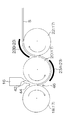
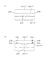
図4は、ダイ16および成形冷却ローラー部17を側方から見た図であり、図5(a)は、成形冷却ローラー部17を下方から見た図である。また、成形冷却ローラー部17の変形例を図5(b)に示す。
4 is a view of the
ニップローラー18および剥離ローラー22は太さが一様な円柱形状を有する一方で、型ローラー20は中央部が細く両端部が太い所謂コンケーブ形状を有する。この型ローラー20のコンケーブ形状は、樹脂シートSの蒲鉾形の偏肉形状の反転形状に対応しており、型ローラー20およびニップローラー18により高温の樹脂シートSが挟圧されて蒲鉾状に成形される。
While the
なお型ローラー20は、図5(b)に示すように、両端部において先細形状のテーパー凹部20Aを有する形状にすることもできる。この場合、樹脂シートSをニップローラー18及び型ローラー20で挟圧したときに、当該樹脂シートSのうちテーパー凹部20Aに対応する部分を容易にカットすることができる。これは、樹脂シートSの両端部(耳部)が所望の膜厚よりも厚くなる傾向があり、その膜厚部がその後の工程において樹脂シートSの反りを助長する可能性を考慮したものである。また、ニップローラー18のうち型ローラー20の膜薄形成部20Bと接触する部分18Aは磨耗し易いので、ニップローラー18の当該当接部18Aに対して、タングステンカーバイト等の超硬材料により超硬処理を施したり焼き入れすることが好ましい。また、型ローラー20及び剥離ローラー22についても同様に、膜薄形成部20B等の当接部に対して超硬処理を施したり焼き入れしたりすることが好ましい。
As shown in FIG. 5B, the
このような構成を有する図5(a)および図5(b)に示す型ローラー20の中央部には、樹脂シートSの膜厚部52に対応する膜厚形成部20Cが設けられている。
A film
そしてダイ16は、図4に示すように、ニップローラー18および型ローラー20の上方において、やや型ローラー20寄りに配置される。また、ニップローラー18、型ローラー20、および剥離ローラー22は、図示しない駆動装置により所定の周速度で図4に示す矢印方向へ回転駆動される。なお、ニップローラー18および剥離ローラー22に対して駆動手段を設けない構成も可能であるが、樹脂シートSの面状(特に裏面)を良好に成形する観点からは、駆動手段によってニップローラー18および剥離ローラー22も回転駆動する構成が好ましい。このような構成において、ダイ16のリップ口42から吐出される溶融樹脂は、ニップローラー18と型ローラー20との間でバンク44を形成するとともに、挟圧部46においてニップローラー18および型ローラー20により挟圧される。ニップローラー18および型ローラー20により偏肉形状が付与された溶融樹脂シートSは、型ローラー20に巻き掛けられた状態で送り出され、剥離ローラー22によって型ローラー20から剥がされる。
As shown in FIG. 4, the
なお、本実施形態では、挟圧部から送られてくる樹脂シートSを加熱する加熱装置23が樹脂シートSの搬送路に沿って複数設けられており、型ローラー20および剥離ローラー22の各々に対向する位置に加熱装置23(23A、23B)が設置されている。
In the present embodiment, a plurality of
図3に示すように、樹脂シートSは、剥離ローラー22から熱処理ゾーン24に送られる。熱処理ゾーン24は、偏肉構造を有する樹脂シートSに対して熱処理を施すゾーンであり、複数の加熱装置23が樹脂シートSの搬送路に沿って設けられている。型ローラー20〜熱処理ゾーン24に亘って設置されるこれらの加熱装置23は非接触式加熱手段であり、加熱効率等の観点から、例えば遠赤外線ヒーターを加熱装置23として好適に用いることができる。加熱装置23の加熱条件は、搬送される樹脂シートSの表面温度がほぼ均一に保たれるようにコントローラーされる。具体的には、樹脂シートSの表面温度がガラス転移温度Tg以下になった後に、樹脂シートSのうち加熱される側の表面の温度差が、幅方向に関して40℃以内となるように、好ましくは30℃以内となるように、より好ましくは20℃以内となるように、さらに好ましくは10℃以内となるように、加熱装置23の加熱条件がコントロールされる。このとき、放射温度計等の温度センサ(図示せず)により樹脂シートSの温度が測定され、この測定温度に基づいて加熱装置23の加熱条件を適宜変更することで、樹脂シートSの表面温度が調整される。
As shown in FIG. 3, the resin sheet S is sent from the peeling
なお、加熱装置23の加熱温度、加熱時間、およびその他の加熱条件は、樹脂シートSの搬送速度や加熱装置23の設置位置に基づいて適宜調整される。例えば、型ローラー20の近傍、剥離ローラー22の近傍、および剥離ローラー22〜熱処理ゾーン24にかけて、樹脂シートSのうち厚みtが「t≦Dmin+(Dmax−Dmin)/2」(ただし、Dminは樹脂シートSのうち膜厚が最も小さい最膜薄部54の膜厚を意味し、Dmaxは樹脂シートSのうち膜厚が最も大きい最膜厚部52の膜厚を意味する)を満たす部分、とりわけ「t≦Dmin+(Dmax−Dmin)/3」を満たす部分を加熱することが好ましい。これは、冷却されやすい膜薄部分を重点的に加熱することで、樹脂シートS全体の温度差を抑えるためである。そのため、図1の断面形状を有する樹脂シートSの場合には両端の最膜薄部54を加熱し、図2の断面形状を有する樹脂シートSの場合には両端の最膜薄部54だけではなく中央の最膜薄部54も加熱することが好ましい。なお、上記式で表される範囲以外の膜厚tを有する部分については、ライン速度等に応じて、加熱の有無や加熱の程度を調整することが好ましい。特に樹脂シートSの表面温度を昇温し過ぎると搬送中に反り等の不具合が発生してしまうことがあるので、加熱装置23の加熱温度や加熱時間を含む加熱条件は、ライン速度や加熱装置23の設置位置に基づいて最適化されることが好ましい。
In addition, the heating temperature, heating time, and other heating conditions of the
熱処理ゾーン24において熱処理を受けた樹脂シートSは、冷却ゾーン26に送られる。冷却ゾーン26は、熱処理ゾーン24から送られてくる樹脂シートSに対して徐冷処理を施すゾーンであり、樹脂シートSの急激な温度変化を防止する。樹脂シートSは、急激に冷却されると表面近傍と内部の収縮量の違いや温度差等に起因する表面形状の悪化や反りが生じ易い。特に膜厚に分布がある偏肉樹脂シートの場合には、急冷等により比較的大きな内部応力が生じやすいので、反りが生じ易い。そのため、冷却ゾーン26における徐冷方法の一例として、前半部では樹脂シートSの膜厚部と膜薄部との間で大きな温度差が生じないように非接触式加熱手段で膜薄部を重点的に加熱して樹脂シートS全体を徐々に自然冷却し、後半部では樹脂シートSに冷風を当てて常温程度まで強制冷却を行う方法がある。
The resin sheet S subjected to the heat treatment in the
なお、上述の熱処理ゾーン24および冷却ゾーン26では、熱処理や冷却に伴う反り等の変形を防いで所望の偏肉形状が保持されるように、樹脂シートSが搬送される。
In the
面状検査機28は、冷却ゾーン26から送られてくる樹脂シートSの表面形状や反りを評価する。面状検査機28による評価はセンサ類を用いた任意の手法で行われ、この評価結果は、前段に設けられたダイ16からの溶融樹脂シートSの吐出制御や、熱処理ゾーン24および冷却ゾーン26における熱処理・冷却制御にフィードバックされる。
The surface inspection machine 28 evaluates the surface shape and warpage of the resin sheet S sent from the cooling
ラミネート機30は、樹脂シートSの表裏面にポリエチレン等の保護フィルムを貼り付けるための一対の引取ローラー36を含んで構成される。
The laminating
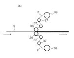
図6は、ラミネート機30において保護フィルムFを樹脂シートSに貼り付ける機構を示す図である。保護フィルムFは、繰り出しローラー38から順次繰り出された後に、複数の転送ローラー37を経て、引取ローラー36に送られる。この引取ローラー36は、樹脂シートSの搬送および保護フィルムFの貼付を同時に行う。すなわち引取ローラー36は、軸回転することによって、前段部(型ローラー20〜ラミネート機30)の樹脂シートSを引っ張って搬送するとともに、後段部(ラミネート機30〜切断機32)の樹脂シートSを押し出すようにして搬送する。また同時に、引取ローラー36は、軸回転することによって、転送ローラー37を介して送られてくる保護フィルムFを樹脂シートSの面に圧着する。引取ローラー36、転送ローラー37および繰り出しローラー38は、樹脂シートSの表面側および裏面側の両方に設けられており、保護フィルムFは樹脂シートSの表面および裏面の両方に圧着される。
FIG. 6 is a view showing a mechanism for attaching the protective film F to the resin sheet S in the laminating
ラミネート機30において保護フィルムFが貼り付けられた樹脂シートSは、図3に示すように、切断機32に送られる。切断機32は、樹脂シートSの幅方向両端部分(耳部)を切除すると共に樹脂シートSを所定長さに切り揃える。切断機32は任意の構成を有することができ、例えば、受け刃および押し当て刃からなるギロチンタイプの切断機32、レーザーカッターや電子ビームを使用した切断機32等を使用することができる。
The resin sheet S to which the protective film F is attached in the laminating
切断機32において所定長さに切り揃えられた樹脂シートSは、スタッカー34に順次積み上げられる。スタッカー34に保管される偏肉樹脂シートSは、別の処理工程に送られたり、商品として出荷される。
The resin sheets S trimmed to a predetermined length in the cutting
上述のような押出成形法を採用する偏肉樹脂シート製造装置10において、本件発明者は、後述する実験の結果、ポリメチルメタクリレート樹脂(PMMA)の樹脂シートSの薄肉部と厚肉部との間で内部歪み量に差をつけることによって、切断後の反りの発生を抑制して所望の形状を長時間にわたって保持することができ、切断された樹脂シートSをスタッカー34に整頓された状態で順次積み重ねることができるという知見を得た。具体的には、PMMAの偏肉樹脂シートSの複屈折量の差が、幅方向に関して、20nm以上であって110nm以下である場合、好ましくは30nm以上であって110nm以下である場合、より好ましくは50nm以上であって110nm以下である場合に、偏肉樹脂シートSにおいて経時的に生じる反りを効果的に低減することができる。上記の範囲の複屈折量を満たす偏肉樹脂シートSは、製造時に適度なテンションが付与されており、優れた形状安定性を示す。
In the uneven thickness resin
このような複屈折量の条件を満たすために、本実施形態では、型ローラー20、剥離ローラー22、および引取ローラー36の回転周速度を調整して、型ローラー20〜引取ローラー36を搬送される偏肉樹脂シートSに適度なテンションが付与される。すなわち、型ローラー20の回転周速度Va、剥離ローラー22の回転周速度Vb、および引取ローラー36の回転周速度Vcが、以下の関係のうち少なくともいずれかを満たすように調整される。
In order to satisfy the condition of such birefringence, in this embodiment, the rotational peripheral speeds of the
Va<Vb
Vb<Vc
Va<Vc
上記の式のうち少なくともいずれか一つを満たした状態で、上記の範囲の複屈折量差が生じるように、所定のテンションが偏肉樹脂シートSに付与され、偏肉樹脂シートSの経時的な反りの発生を防ぐことができる。
V a <V b
V b <V c
V a <V c
In a state where at least one of the above equations is satisfied, a predetermined tension is applied to the uneven thickness resin sheet S so that a birefringence amount difference in the above range is generated. Generation of warping can be prevented.
なお、上記範囲の複屈折量差を付与する際には、簡易性および信頼性の観点から、型ローラー20〜ラミネート機30(冷却ゾーン26)の間、すなわち偏肉形状が付与されてから冷却されて物性が安定するまでの間に、所定のテンションを偏肉樹脂シートSに付与することが望ましい。特に均一な品質を確保する観点からは、偏肉樹脂シートSの温度がガラス転移温度近傍もしくはガラス転移温度以上の状態で、
上記のテンションを偏肉樹脂シートSに付与することが好ましい。
In addition, when providing the birefringence amount difference in the above range, from the viewpoint of simplicity and reliability, cooling is performed between the
It is preferable to apply the above tension to the uneven thickness resin sheet S.
また、型ローラー20、剥離ローラー22、および引取ローラー36の回転周速度を調整する以外の方法で、偏肉樹脂シートSに上記範囲の複屈折量差を生じさせてもよく、例えば型ローラー20〜引取ローラー36の範囲において樹脂シートSに所定のテンションを付与するためのローラー等の器具を設置してもよい。
Further, the birefringence amount difference in the above range may be generated in the uneven thickness resin sheet S by a method other than adjusting the rotational peripheral speeds of the
なお、ニップローラー18、型ローラー20、及び剥離ローラー22の材質としては、各種鉄鋼部材、ステンレス鋼、銅、亜鉛、真鍮、これらの金属材料を芯金として表面にゴムライニングしたもの、これらの金属材料にHCrメッキ、Cuメッキ、Niメッキ等のメッキを施したもの、セラミックス、及び各種の複合材料が採用することができる。
In addition, as materials of the
また、型ローラー20の表面の逆蒲鉾形状は、公知の加工方法により形成することが可能であり、例えば、研削加工、超音波加工、放電加工、NC旋盤による切削加工、仕上げバフ加工、等を適宜組み合わせて形成することが可能である。型ローラー表面の表面粗さは、中心線平均粗さRaで0.5μm以下とすることが好ましく、0.2μm以下とすることがより好ましい。
In addition, the reverse shape of the surface of the
また、ニップローラー18、型ローラー20、及び剥離ローラー22には、偏肉樹脂シートSの蒲鉾形状に対応するような冷却温度分布を樹脂シートSに付与するための温度調整手段(図示せず)が設けられる。この温度調整手段として、例えば、温度調節された冷却液体を型ローラー20の内部の一端側から他端側に流す構成を採用することができる。
Further, the
ニップローラー18には、図示しない加圧手段が設けられており、型ローラー20との間の樹脂シートSを所定の圧力で挟圧することができるようになっている。この加圧手段は、ニップローラー18と型ローラー20との接触点における法線方向に圧力を付与する構成のものであり、モータ駆動手段、エアシリンダ、油圧シリンダ等の公知の各種手段を採用することができる。また、ニップローラー18には、挟圧力の反力による撓みが生じにくくなるような構成を採用することもできる。このような構成としては、ニップローラー18の背面側(型ローラー20とは反対側)に図示しないバックアップローラーを設ける構成、中高状のクラウン形状を採用する構成、ローラーの軸方向中央部の剛性が大きくなるような強度分布を付けたローラーの構成、或いはこれらを組み合わせた構成等を採用することができる。
The
なお、偏肉樹脂シートSの断面形状は、当該偏肉樹脂シートSを挟圧成形するニップローラーおよび型ローラーの形状に応じて適宜変更することができ、ニップローラーおよび型ローラーの形状を変えることで、様々な断面形状を有する偏肉樹脂シートを製造することができる。 In addition, the cross-sectional shape of the uneven thickness resin sheet S can be appropriately changed according to the shapes of the nip roller and the mold roller for sandwiching the uneven thickness resin sheet S, and the shapes of the nip roller and the mold roller can be changed. Thus, uneven thickness resin sheets having various cross-sectional shapes can be manufactured.
また、ニップローラー18および剥離ローラー22の表面は鏡面状に加工されていることが好ましい。このような表面にすることにより、成形後の樹脂シートSの裏面を良好な状態に仕上げることができる。そして、ニップローラー18および剥離ローラー22の表面粗さは、中心線平均粗さRaで0.5μm以下とするのが好ましく、0.2μm以下とするのがより好ましい。
Moreover, it is preferable that the surface of the
また、ニップローラー18、型ローラー20、及び剥離ローラー22には、ローラー表面の温度をローラー幅方向に関してモニターできるように、複数の表面温度測定手段(図示せず)を設けることが好ましい。このような表面温度測定手段としては、赤外線温度計、放射式温度計等の公知の各種測定手段が採用できる。
The
上記樹脂シートを、いわゆるアニール処理により歪みを除去することで、二次加の際に生じる反りを低減することもできる。アニール処理の方法としては温度設定された炉の中にシートを一定時間入れて加熱する方法や、遠赤外線を用いてシートを加熱する方法などがある。シートの加熱温度は、樹脂のガラス転移温度Tgを基準に、Tg−30℃以上であってTg以下であることが好ましい。加熱している際に保持具でシート形状を矯正して、アニールする際のシートの変形を抑制することもできる。 By removing the distortion of the resin sheet by a so-called annealing treatment, it is possible to reduce the warp that occurs during the secondary addition. As a method of annealing treatment, there are a method in which a sheet is placed in a temperature-set furnace for a certain period of time and a method in which the sheet is heated using far infrared rays. The heating temperature of the sheet is preferably Tg-30 ° C. or more and Tg or less based on the glass transition temperature Tg of the resin. It is also possible to correct the sheet shape with the holder during heating and suppress deformation of the sheet during annealing.
本発明は、上述の実施の形態およびその変形例に限定されるものではなく、当業者の知識に基づいて各種の設計変更等の変形が加えられることも可能であり、そのような変形が加えられた実施の形態も本発明の範囲に含まれうる。 The present invention is not limited to the above-described embodiments and modifications thereof, and various modifications such as design changes can be added based on the knowledge of those skilled in the art. The described embodiments can also be included in the scope of the present invention.
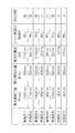
本件発明者は、上述の実施形態に基づいて、以下の実施例および比較例に記載する条件で偏肉樹脂シートを製造し、偏肉樹脂シートの反りを評価した(図7参照)。偏肉樹脂シートの反りの評価は、切断機32によって樹脂シートSを所望形状に切断してから約24時間にわたって行われた。また、偏肉樹脂シートSの複屈折量は、図8に示す測定装置により測定した。すなわち、試料の偏肉樹脂シートSの複屈折量を、歪検査器50(株式会社ルケオ製:LSM−401)により、いわゆるセナルモン法に基づいて測定した。なお、他の装置および他の方法によって樹脂シートSの複屈折量を測定してもよい。
(実施例1)
図3に示す偏肉樹脂シート製造装置10において、PMMA(旭化成株式会社製80NH、ガラス転移温度110℃)を原料樹脂として使用し、温度255℃に設定したダイ(Tダイ)16より100kg/hrで溶融樹脂をシート状に押し出した。そして成形ニップローラー18、型ローラー20、剥離ローラー22、熱処理ゾーン24、冷却ゾーン26、およびラミネート機30を介して、図1に示す蒲鉾形状の断面を有する偏肉樹脂シートSを製造した。そして切断機32により樹脂シートSの両端を切断した。このようにして製造された樹脂シートSは、乾燥状態において、シート幅方向に関する断面の幅が594mm、最膜薄部54の膜厚Dminが2mm、最膜厚部52の膜厚Dmaxが3.8mmであった。
Based on the above-described embodiment, the present inventors manufactured an uneven thickness resin sheet under the conditions described in the following examples and comparative examples, and evaluated the warpage of the uneven thickness resin sheet (see FIG. 7). The warpage of the uneven thickness resin sheet was evaluated for about 24 hours after the resin sheet S was cut into a desired shape by the cutting
Example 1
In the uneven thickness resin
上記偏肉樹脂シートSの製造時には、成形ニップローラー18、型ローラー20、および剥離ローラー22が、表面温度がそれぞれ70℃、90℃、95℃であった。成形ニップローラー18および剥離ローラー22のローラー径はΦ350mmであり、型ローラー20の膜薄形成部20Bのローラー径はΦ350mmであり、膜厚形成部20Cのローラー径はΦ345.6mmであり、引取ローラー36のローラー径はΦ195mmであった。また、成形ニップローラー18、型ローラー20、剥離ローラー22、搬送ニップローラー25の表面は硬質クロムメッキ処理されており、引取ローラー36の表面材質はEPTゴムであった。また、成形ニップローラー18、型ローラー20、および剥離ローラー22の各々間のクリアランス(線圧)、搬送ニップローラー25間のクリアランス(線圧)、および引取ローラー36間のクリアランス(線圧)は、上記の断面サイズを有する樹脂シートSが製造されるように適宜調整した。また、加熱装置23として遠赤外線ヒーターを使用し、ローラー接触時および搬送中の樹脂シート表面温度が均一になるように適宜加熱した。成形ニップローラー18、型ローラー20、剥離ローラー22および引取ローラー36の周速度は、それぞれ0.750m/min、0.750m/min、0.764m/min、0.775m/minだった。
この偏肉樹脂シートSの厚み方向の複屈折量は、最膜厚部52において最小値Bmin(Bmin=55nm)を示し、最膜薄部54において最大値Bmax(Bmax=165nm)を示し、シート幅方向に関する偏肉樹脂シートSの複屈折量の最大差ΔBは110nm(ΔB=Bmax−Bmin=165nm−55nm=110nm)であった。
At the time of manufacturing the uneven thickness resin sheet S, the surface temperatures of the molding nip
The birefringence amount in the thickness direction of the uneven thickness resin sheet S shows the minimum value B min (B min = 55 nm) in the
このような特性を有する偏肉樹脂シートSを、切断機32により切断してから約24時間にわたり観察したところ、偏肉樹脂シートSの最大反り量は1.1mmであり、経時的な反りの変化もほとんど見られなかった。したがって、本実施例のようにシート幅方向に関する偏肉樹脂シートSの複屈折量の差ΔBが110nmの場合には、偏肉樹脂シートSの経時的な反りを効果的に抑制して、所望のシート形状を長時間にわたって維持することができ、複数の偏肉樹脂シートSを整頓した状態で積み重ねることができることが確認された。
(実施例2)
実施例1と同様に偏肉樹脂シート製造装置10を用いて、図1に示す断面形状を有するPMMAの偏肉樹脂シートSを、押出成形法により製造した。ダイからの押出量は135kg/hrであり、成形ニップローラー18、型ローラー20、および剥離ローラー22の表面温度はそれぞれ70℃、80℃、70℃であり、ニップローラー18、型ローラー20、剥離ローラー22および引取ローラー36の回転速度をそれぞれ1.000、1.000、1.023、1.045m/minとした。その他の条件は実施例1と同じであった。
この偏肉樹脂シートSの厚み方向の複屈折量は、最膜厚部52において最小値Bmin(Bmin=50nm)を示し、最膜薄部54において最大値Bmax(Bmax=110nm)を示し、シート幅方向に関する偏肉樹脂シートSの複屈折量の最大差ΔBは60nm(ΔB=Bmax−Bmin=110nm−50nm=60nm)であった。他の特性は、実施例1で用いた偏肉樹脂シートSとほぼ同じであった。
When the uneven thickness resin sheet S having such characteristics is observed for about 24 hours after being cut by the cutting
(Example 2)
Using the uneven thickness resin
The birefringence amount in the thickness direction of the uneven thickness resin sheet S shows the minimum value B min (B min = 50 nm) in the maximum
このような特性を有する偏肉樹脂シートSを、切断機32により切断してから約24時間にわたり観察したところ、偏肉樹脂シートSの最大反り量は0.8mm であり、経時的な反りの変化もほとんど見られなかった。したがって、実施例1と同様に、本例の偏肉樹脂シートSも経時的な反りを効果的に抑制することができ、所望のシート形状を長時間にわたって維持することができ、複数の偏肉樹脂シートSを整頓した状態で積み重ねることができることが確認された。
(実施例3)
実施例1と同様に偏肉樹脂シート製造装置10を用いて、図2に示す断面形状を有するPMMAの偏肉樹脂シートSを、押出成形法により製造した。この偏肉樹脂シートSは、乾燥状態において、シート幅方向に関する断面の幅が1200mm、最膜薄部54の膜厚Dminが2mm、最膜厚部52の膜厚Dmaxが3.8mmであった。吐出量を200kg/hrとして、その他の条件は実施例2と同じであった。この偏肉樹脂シートSの厚み方向の複屈折量は、最膜厚部52において最小値Bmin(Bmin=55nm)を示し、最膜薄部54において最大値Bmax(Bmax=165nm)を示し、シート幅方向に関する偏肉樹脂シートSの複屈折量の最大差ΔBは110nm(ΔB=Bmax−Bmin=165nm−55nm=60nm)であった。
When the uneven thickness resin sheet S having such characteristics is observed for about 24 hours after being cut by the cutting
(Example 3)
Using the uneven thickness resin
このような特性を有する偏肉樹脂シートSを、切断機32により切断してから約24時間にわたり観察したところ、偏肉樹脂シートSの最大反り量は1.0mmであり、経時的な反りの変化もほとんど見られなかった。したがって、本実施例のようにシート幅方向に関して最膜厚部52および最膜薄部54が周期的に配される断面形状の偏肉樹脂シートSであっても、厚み方向に適切な複屈折量を付与することで、経時的な反りを効果的に抑制して所望のシート形状を長時間にわたって維持することができ、複数の偏肉樹脂シートSを整頓した状態で積み重ねることができることが確認された。
(実施例4)
実施例2と同様に偏肉樹脂シート製造装置10を用いて、図1に示す断面形状を有するPMMAの偏肉樹脂シートSを、押出成形法により製造した。剥離ローラー22の径をΦ500mmとし、引取ローラー36の回転速度を1.031m/minとして、その他の条件は実施例2と同じであった。この偏肉樹脂シートSの厚み方向の複屈折量は、最膜厚部52において最小値Bmin(Bmin=45nm)を示し、最膜薄部54において最大値Bmax(Bmax=65nm)を示し、シート幅方向に関する偏肉樹脂シートSの複屈折量の最大差ΔBは20nm(ΔB=Bmax−Bmin=65nm−45nm=20nm)であった。他の特性は、実施例1で用いた偏肉樹脂シートSとほぼ同じであった。
When the uneven thickness resin sheet S having such characteristics is observed for about 24 hours after being cut by the cutting
Example 4
Using the uneven thickness resin
このような特性を有する偏肉樹脂シートSを、切断機32により切断してから約24時間にわたり観察したところ、偏肉樹脂シートSの最大反り量は1.3mm であり、わずかな反りが経時的に生じたが、実用上支障のないレベルの反りであった。したがって、実施例1と同様に、本例の偏肉樹脂シートSも経時的な反りを効果的に抑制することができ、所望のシート形状を長時間にわたって維持することができ、複数の偏肉樹脂シートSを整頓した状態で積み重ねることができることが確認された。
(実施例5)
実施例4と同様に偏肉樹脂シート製造装置10を用いて、図1に示す断面形状を有するPMMAの偏肉樹脂シートSを、押出成形法により製造した。引取ローラー36の回転速度を1.040m/minとして、その他の条件は実施例4と同じであった。この偏肉樹脂シートSの厚み方向の複屈折量は、最膜厚部52において最小値Bmin(Bmin=50nm)を示し、最膜薄部54において最大値Bmax(Bmax=85nm)を示し、シート幅方向に関する偏肉樹脂シートSの複屈折量の最大差ΔBは30nm(ΔB=Bmax−Bmin=85nm−50nm=35nm)であった。他の特性は、実施例1で用いた偏肉樹脂シートSとほぼ同じであった。
When the uneven thickness resin sheet S having such characteristics was observed for about 24 hours after being cut by the cutting
(Example 5)
Using the uneven thickness resin
このような特性を有する偏肉樹脂シートSを、切断機32により切断してから約24時間にわたり観察したところ、偏肉樹脂シートSの最大反り量は1.1mmであり、実施例4の偏肉樹脂シートSよりも経時的な反りは低減し、実用上支障のないレベルの反りであった。したがって、実施例1と同様に、本例の偏肉樹脂シートSも経時的な反りを効果的に抑制することができ、所望のシート形状を長時間にわたって維持することができ、複数の偏肉樹脂シートSを整頓した状態で積み重ねることができることが確認された。
(実施例6)
実施例4と同様に偏肉樹脂シート製造装置10を用いて、図1に示す断面形状を有するPMMAの偏肉樹脂シートSを、押出成形法により製造した。引取ローラー36の回転速度を1.046m/minとして、その他の条件は実施例4と同じであった。この偏肉樹脂シートSの厚み方向の複屈折量は、最膜厚部52において最小値Bmin(Bmin=50nm)を示し、最膜薄部54において最大値Bmax(Bmax=100nm)を示し、シート幅方向に関する偏肉樹脂シートSの複屈折量の最大差ΔBは50nm(ΔB=Bmax−Bmin=100nm−50nm=50nm)であった。他の特性は、実施例1で用いた偏肉樹脂シートSとほぼ同じであった。
When the uneven thickness resin sheet S having such characteristics was observed for about 24 hours after being cut by the cutting
(Example 6)
Using the uneven thickness resin
このような特性を有する偏肉樹脂シートSを、切断機32により切断してから約24時間にわたり観察したところ、偏肉樹脂シートSの最大反り量は0.8mmであり、経時的な反りの変化もほとんど見られなかった。したがって、実施例1と同様に、本例の偏肉樹脂シートSも経時的な反りを効果的に抑制することができ、所望のシート形状を長時間にわたって維持することができ、複数の偏肉樹脂シートSを整頓した状態で積み重ねることができることが確認された。
(比較例1)
実施例1と同様に、偏肉樹脂シート製造装置10を用いて、図1に示す断面形状を有するPMMAの偏肉樹脂シートSを、押出成形法により製造した。引取ローラー36の回転速度を0.760m/minとして、その他の条件は実施例1と同じであった。この偏肉樹脂シートSの厚み方向の複屈折量は、略均一であり、最膜厚部52および最膜薄部54のいずれにおいても30nmを示し、シート幅方向に関する偏肉樹脂シートSの複屈折量の最大差ΔBも0nmであった。他の特性は、実施例1で用いた偏肉樹脂シートSとほぼ同じであった。
When the uneven thickness resin sheet S having such characteristics is observed for about 24 hours after being cut by the cutting
(Comparative Example 1)
In the same manner as in Example 1, an uneven thickness resin
このような特性を有する偏肉樹脂シートSを、切断機32により切断してから約24時間にわたり観察したところ、シート切断直後は反りがほとんどなかったが、時間が経つにつれて最大で10mm以上の非常に大きな反りが生じてしまった。このように本例では、所望のシート形状を長時間にわたって維持することができず、複数の偏肉樹脂シートSを整頓した状態で積み重ねることができなかった。
(比較例2)
実施例2と同様に、偏肉樹脂シート製造装置10を用いて、図1に示す断面形状を有するPMMAの偏肉樹脂シートSを、押出成形法により製造した。引取ローラー36の回転速度を1.020m/minとして、その他の条件は実施例1と同じであった。この偏肉樹脂シートSの厚み方向の複屈折量は、最膜厚部52において最小値Bmin(Bmin=30nm)を示し、最膜薄部54において最大値Bmax(Bmax=40nm)を示し、シート幅方向に関する偏肉樹脂シートSの複屈折量の最大差ΔBは10nm(ΔB=Bmax−Bmin=40nm−30nm=10nm)であった。他の特性は、実施例1で用いた偏肉樹脂シートSとほぼ同じであった。
When the uneven thickness resin sheet S having such characteristics was observed for about 24 hours after being cut by the cutting
(Comparative Example 2)
Similarly to Example 2, an uneven thickness resin
このような特性を有する偏肉樹脂シートSを、切断機32により切断してから約24時間にわたり観察したところ、偏肉樹脂シートSの最大反り量は10mm以上であり、非常に大きな反りが生じてしまった。このように本例では、所望のシート形状を長時間にわたって維持することができず、複数の偏肉樹脂シートSを整頓した状態で積み重ねることができなかった。
When the uneven thickness resin sheet S having such characteristics is observed for about 24 hours after being cut by the cutting
上記の実施例及び比較例の評価結果を図7に示す。図7からも明らかなように、PMMAの偏肉樹脂シートSでは、シート幅方向に関する複屈折量の差が20nm以上110nm以下である場合、より好ましくは30nm以上110nm以下である場合、さらに好ましくは50nm以上110nm以下である場合に、経時的な反りを効果的に低減することができることが確認された。また、実施例1及び実施例3の比較からも明らかなように、シート幅方向に関する上記の複屈折量の差の関係等は、樹脂シートSの幅方向の断面形状に周期性を持たせた場合であっても、有効であることが分かった。 The evaluation result of said Example and a comparative example is shown in FIG. As is clear from FIG. 7, in the case of the uneven thickness resin sheet S of PMMA, when the difference in birefringence in the sheet width direction is 20 nm or more and 110 nm or less, more preferably 30 nm or more and 110 nm or less, further preferably It was confirmed that warpage with time can be effectively reduced when the thickness is 50 nm or more and 110 nm or less. Further, as is clear from the comparison between Example 1 and Example 3, the relationship of the difference in the birefringence amount with respect to the sheet width direction gave periodicity to the cross-sectional shape of the resin sheet S in the width direction. Even in cases, it proved to be effective.
なお、上記の各種寸法は、基本的には偏肉樹脂シートの乾燥時を基準としている。 In addition, said various dimensions are fundamentally based on the time of drying of the uneven thickness resin sheet.
10…偏肉樹脂シート製造装置、11…原料調製装置、12…押出機、13…原料供給管、14…溶融樹脂供給管、16…ダイ、17…成形冷却ローラー部、18…ニップローラー、20…型ローラー、20A…テーパー凹部、20B…膜薄形成部、20C…膜厚形成部、22…剥離ローラー、23…加熱装置、24…熱処理ゾーン、26…冷却ゾーン、28…面状検査機、30…ラミネート機、32…切断機、34…スタッカー、36…引取ローラー、37…転送ローラー、38…繰り出しローラー、42…リップ口、44…バンク、46…挟圧部、50…歪検査器、52…膜厚部、54…膜薄部、S…樹脂シート、F…保護フィルム
DESCRIPTION OF
Claims (5)
前記幅方向に関して、膜厚が最も大きい最膜厚部と膜厚が最も小さい最膜薄部との膜厚差は、0.5mm以上であって5mm以下であり、
前記幅方向に関して、複屈折量の差が20nm以上であって110nm以下であることを特徴とする偏肉樹脂シート。 An uneven thickness resin sheet of polymethylmethacrylate resin that has an uneven thickness in the width direction,
Regarding the width direction, the film thickness difference between the largest film thickness portion with the largest film thickness and the smallest film thickness portion with the smallest film thickness is 0.5 mm or more and 5 mm or less,
The uneven thickness resin sheet, wherein the difference in birefringence is 20 nm or more and 110 nm or less with respect to the width direction.
前記複数の最膜薄部は、200mm以上のピッチを有することを特徴とする請求項1または2に記載の偏肉樹脂シート。 The uneven thickness resin sheet includes a plurality of the thinnest film portions in the width direction,
The uneven thickness resin sheet according to claim 1, wherein the plurality of thinnest film portions have a pitch of 200 mm or more.
Priority Applications (1)
| Application Number | Priority Date | Filing Date | Title |
|---|---|---|---|
| JP2008068206A JP2009220439A (en) | 2008-03-17 | 2008-03-17 | Uneven-thickness resin sheet and manufacturing method of uneven-thickness resin sheet |
Applications Claiming Priority (1)
| Application Number | Priority Date | Filing Date | Title |
|---|---|---|---|
| JP2008068206A JP2009220439A (en) | 2008-03-17 | 2008-03-17 | Uneven-thickness resin sheet and manufacturing method of uneven-thickness resin sheet |
Publications (1)
| Publication Number | Publication Date |
|---|---|
| JP2009220439A true JP2009220439A (en) | 2009-10-01 |
Family
ID=41237755
Family Applications (1)
| Application Number | Title | Priority Date | Filing Date |
|---|---|---|---|
| JP2008068206A Pending JP2009220439A (en) | 2008-03-17 | 2008-03-17 | Uneven-thickness resin sheet and manufacturing method of uneven-thickness resin sheet |
Country Status (1)
| Country | Link |
|---|---|
| JP (1) | JP2009220439A (en) |
-
2008
- 2008-03-17 JP JP2008068206A patent/JP2009220439A/en active Pending
Similar Documents
| Publication | Publication Date | Title |
|---|---|---|
| US20100109185A1 (en) | Method and apparatus for manufacturing uneven thickness resin sheet | |
| JP2009040009A (en) | Manufacturing method and apparatus for uneven thickness resin sheet | |
| JP2010058285A (en) | Method of manufacturing resin sheet | |
| JP2010058437A (en) | Method of manufacturing resin sheet | |
| WO2010029875A1 (en) | Process for producing resin sheet with thickness unevenness | |
| WO2012102178A1 (en) | Method and apparatus for producing resin film | |
| WO2010089944A1 (en) | Method of manufacturing resin sheet with uneven thickness and device for manufacturing resin sheet with uneven thickness | |
| JP2008246866A (en) | Method and apparatus for producing particle-containing resin sheet | |
| WO2009116423A1 (en) | Method for producing partially thick resin sheet | |
| JP2006056214A (en) | Manufacturing method of resin sheet | |
| CN101646546A (en) | Method and apparatus for producing uneven thickness resin sheet | |
| JP2008246867A (en) | Manufacturing method and apparatus for uneven thickness resin sheet | |
| JP2009274389A (en) | Method and apparatus for manufacturing of thickness-biased resin sheet | |
| JP2010188571A (en) | Method and apparatus for manufacturing thickness-biased resin sheet | |
| CN101980854A (en) | Manufacturing method of resin sheet with uneven thickness | |
| JP2011161729A (en) | Method of manufacturing uneven-thickness resin sheet | |
| US20080088052A1 (en) | Method Of Producing A Resin Sheet | |
| JP2009220439A (en) | Uneven-thickness resin sheet and manufacturing method of uneven-thickness resin sheet | |
| JP2009220440A (en) | Manufacturing method of uneven-thickness resin sheet | |
| JP4995163B2 (en) | Manufacturing method of uneven thickness resin sheet | |
| JP2009220442A (en) | Manufacturing method of uneven-thickness resin sheet | |
| JP2009220441A (en) | Manufacturing method of uneven-thickness resin sheet | |
| JP2010201712A (en) | Method and device for manufacturing resin sheet | |
| JP2009226773A (en) | Method for manufacturing uneven thickness resin sheet, stacking method and stacked article | |
| JP2009274387A (en) | Resin sheet with protective film, and method for manufacturing the same |