JP2009209935A - Method and device for regulating fluid flow in gas turbine engine - Google Patents
Method and device for regulating fluid flow in gas turbine engine Download PDFInfo
- Publication number
- JP2009209935A JP2009209935A JP2009043297A JP2009043297A JP2009209935A JP 2009209935 A JP2009209935 A JP 2009209935A JP 2009043297 A JP2009043297 A JP 2009043297A JP 2009043297 A JP2009043297 A JP 2009043297A JP 2009209935 A JP2009209935 A JP 2009209935A
- Authority
- JP
- Japan
- Prior art keywords
- piston
- valve
- fluid flow
- fluid
- gas turbine
- Prior art date
- Legal status (The legal status is an assumption and is not a legal conclusion. Google has not performed a legal analysis and makes no representation as to the accuracy of the status listed.)
- Pending
Links
Images


Classifications
-
- F—MECHANICAL ENGINEERING; LIGHTING; HEATING; WEAPONS; BLASTING
- F01—MACHINES OR ENGINES IN GENERAL; ENGINE PLANTS IN GENERAL; STEAM ENGINES
- F01D—NON-POSITIVE DISPLACEMENT MACHINES OR ENGINES, e.g. STEAM TURBINES
- F01D17/00—Regulating or controlling by varying flow
- F01D17/20—Devices dealing with sensing elements or final actuators or transmitting means between them, e.g. power-assisted
- F01D17/22—Devices dealing with sensing elements or final actuators or transmitting means between them, e.g. power-assisted the operation or power assistance being predominantly non-mechanical
- F01D17/26—Devices dealing with sensing elements or final actuators or transmitting means between them, e.g. power-assisted the operation or power assistance being predominantly non-mechanical fluid, e.g. hydraulic
-
- F—MECHANICAL ENGINEERING; LIGHTING; HEATING; WEAPONS; BLASTING
- F01—MACHINES OR ENGINES IN GENERAL; ENGINE PLANTS IN GENERAL; STEAM ENGINES
- F01D—NON-POSITIVE DISPLACEMENT MACHINES OR ENGINES, e.g. STEAM TURBINES
- F01D17/00—Regulating or controlling by varying flow
- F01D17/10—Final actuators
- F01D17/12—Final actuators arranged in stator parts
- F01D17/14—Final actuators arranged in stator parts varying effective cross-sectional area of nozzles or guide conduits
- F01D17/148—Final actuators arranged in stator parts varying effective cross-sectional area of nozzles or guide conduits by means of rotatable members, e.g. butterfly valves
-
- F—MECHANICAL ENGINEERING; LIGHTING; HEATING; WEAPONS; BLASTING
- F04—POSITIVE - DISPLACEMENT MACHINES FOR LIQUIDS; PUMPS FOR LIQUIDS OR ELASTIC FLUIDS
- F04D—NON-POSITIVE-DISPLACEMENT PUMPS
- F04D27/00—Control, e.g. regulation, of pumps, pumping installations or pumping systems specially adapted for elastic fluids
- F04D27/02—Surge control
- F04D27/0253—Surge control by throttling
-
- F—MECHANICAL ENGINEERING; LIGHTING; HEATING; WEAPONS; BLASTING
- F05—INDEXING SCHEMES RELATING TO ENGINES OR PUMPS IN VARIOUS SUBCLASSES OF CLASSES F01-F04
- F05D—INDEXING SCHEME FOR ASPECTS RELATING TO NON-POSITIVE-DISPLACEMENT MACHINES OR ENGINES, GAS-TURBINES OR JET-PROPULSION PLANTS
- F05D2220/00—Application
- F05D2220/30—Application in turbines
- F05D2220/32—Application in turbines in gas turbines
-
- Y—GENERAL TAGGING OF NEW TECHNOLOGICAL DEVELOPMENTS; GENERAL TAGGING OF CROSS-SECTIONAL TECHNOLOGIES SPANNING OVER SEVERAL SECTIONS OF THE IPC; TECHNICAL SUBJECTS COVERED BY FORMER USPC CROSS-REFERENCE ART COLLECTIONS [XRACs] AND DIGESTS
- Y10—TECHNICAL SUBJECTS COVERED BY FORMER USPC
- Y10T—TECHNICAL SUBJECTS COVERED BY FORMER US CLASSIFICATION
- Y10T137/00—Fluid handling
- Y10T137/7722—Line condition change responsive valves
- Y10T137/7758—Pilot or servo controlled
- Y10T137/7762—Fluid pressure type
Abstract
Description
本発明は概してガスタービンエンジンに関し、より詳細には、ガスタービンエンジンの流体流を調整するのに使用されるバルブアセンブリに関する。 The present invention relates generally to gas turbine engines, and more particularly to valve assemblies used to regulate fluid flow in gas turbine engines.
通常、ガスタービンエンジンは、圧縮機と、燃焼器と、少なくとも1つのタービンとを含む。圧縮機によって空気が圧縮され、燃料と混合されて燃焼器に運ばれる。混合気がそこで点火されて高温燃焼ガスが発生し、燃焼ガスはタービンに運ばれる。タービンは燃焼ガスからエネルギーを抽出して、圧縮機に動力を供給するだけでなく、飛行中の航空機を推進したり、発電機等の負荷に動力を供給したりするための有効な仕事を発生させることができる。 A gas turbine engine typically includes a compressor, a combustor, and at least one turbine. Air is compressed by the compressor, mixed with fuel, and carried to the combustor. The air-fuel mixture is ignited there to produce hot combustion gases that are carried to the turbine. The turbine not only extracts energy from the combustion gas and supplies power to the compressor, but also generates useful work to propel the aircraft in flight and to supply power to generators and other loads. Can be made.
ガスタービンエンジンは、通常、圧縮機およびタービンの周りに円周方向に延在するエンジンケーシングを含む。少なくとも一部の既知のエンジンの内部では、ケーシングの外面に連結された複数のダクトおよびバルブを用いてエンジンの1つの領域から流体流を運んで、エンジンの別の領域で使用したり、機外へ排出したりする。例えば、そのようなダクトおよびバルブは、環境管理システム(ECS)の一部を形成することがある。 Gas turbine engines typically include an engine casing that extends circumferentially around the compressor and turbine. Inside at least some known engines, a plurality of ducts and valves connected to the outer surface of the casing are used to carry fluid flow from one area of the engine for use in other areas of the engine, Or to discharge. For example, such ducts and valves may form part of an environmental management system (ECS).
少なくとも一部の既知のバルブアセンブリは、高温および/または高圧状態にある流体流を制御するのに使用される。そのようなバルブアセンブリは、配管の隣接する部分の間に連結される略円筒バルブ本体を含む。バルブ本体は、バルブを通る流体流を制御するように選択的に位置決めすることができるバルブ密封機構を含む。より詳細には、少なくとも一部の既知のバルブは、バルブ本体の外部に配置され、バルブ密封機構を選択的に位置決めするのに必要な原動力を供給するようにバルブ密封機構に連結されるピストン/シリンダ装置を含む。 At least some known valve assemblies are used to control fluid flow at high temperature and / or high pressure conditions. Such a valve assembly includes a generally cylindrical valve body coupled between adjacent portions of tubing. The valve body includes a valve sealing mechanism that can be selectively positioned to control fluid flow through the valve. More particularly, at least some known valves are located on the exterior of the valve body and are connected to the valve sealing mechanism to provide the motive force necessary to selectively position the valve sealing mechanism. Includes cylinder devices.
ピストン/シリンダ装置は主バルブ本体からオフセットしているので、バルブアセンブリの重心は、一般的にバルブ本体の中心軸線からある距離だけずれている。そのような重心偏心は、エンジン作動時に、バルブアセンブリ、隣接する配管および支持ブラケットに曲げ応力を誘発する場合がある。用途によっては、ピストン/シリンダ装置の物理的寸法および重量もまた、エンジン設計のダクト経路指定段階での問題点を示すことがある。 Since the piston / cylinder device is offset from the main valve body, the center of gravity of the valve assembly is generally offset by a distance from the central axis of the valve body. Such center of gravity eccentricity may induce bending stresses on the valve assembly, adjacent piping and support brackets during engine operation. In some applications, the physical dimensions and weight of the piston / cylinder device may also present problems during the duct routing phase of engine design.
一部の既知のバルブアセンブリは、バルブ密封機構に通じる配管に屈曲部を設けることによって、これらの問題を克服しようと努力してきた。この変更の目的は、バルブ密封機構をピストンと垂直に配向し、さらに力伝達ピンをピストン移動方向と垂直に配向することであった。しかしながら、この設計は、ピストンとバルブ密封機構の中間でウィッシュボーン構成を使う必要がある。ウィッシュボーンによって振動姿態が生じ、結果的に好ましくない摩耗問題または部品応力につながることがある。ウィッシュボーンはまた接続ピン用のスロットも含んでおり、埃や水分が作動キャビティに入り込むことが可能になってしまう。 Some known valve assemblies have attempted to overcome these problems by providing bends in the piping leading to the valve sealing mechanism. The purpose of this change was to orient the valve sealing mechanism perpendicular to the piston and to orient the force transmission pin perpendicular to the direction of piston movement. However, this design requires the use of a wishbone configuration between the piston and valve sealing mechanism. Wishbones can cause vibrational appearances that can result in undesirable wear problems or component stress. The wishbone also includes slots for connecting pins, allowing dust and moisture to enter the working cavity.
一例示的実施形態において、ガスタービンエンジンの流体流調整方法は、開放バルブと、第1屈曲部と、第2屈曲部とを有する流管を設けるステップと、該流管に流体を流すステップと、軸方向に動くようにピストンを作動させるステップと、該ピストンの軸方向運動によって該バルブを閉鎖するステップとを含む。 In an exemplary embodiment, a gas turbine engine fluid flow regulation method includes providing a flow tube having an open valve, a first bend, and a second bend, and flowing a fluid through the flow tube. , Actuating a piston for axial movement and closing the valve by axial movement of the piston.
別の例示的実施形態において、ガスタービンエンジンの流体流調整方法は、軸線と、該軸線と平行な回転軸であって、該回転軸と平行で該軸線を通過する平面からオフセットされる該回転軸を有するバルブとを有する流管を設けるステップと、該流管に流体を流すステップと、軸方向に動くようにピストンを作動させるステップと、該ピストンの軸方向運動によって該回転軸を回転させるステップと、該回転軸の回転によって該バルブの位置を変えるステップとを含む。 In another exemplary embodiment, a gas turbine engine fluid flow conditioning method includes: rotating an axis and a rotation axis parallel to the axis that is offset from a plane parallel to the axis of rotation and passing through the axis. Providing a flow tube having a valve having a shaft, flowing a fluid through the flow tube, actuating a piston to move axially, and rotating the rotating shaft by axial movement of the piston And a step of changing the position of the valve by rotation of the rotating shaft.
図1は、1つ以上のバルブアセンブリ104を含む複数のダクト102を有するガスタービンエンジン100の底面図である。エンジン100は、圧縮機106と、燃焼器108と、タービン110とを含む。エンジン100はまた、破線で示すさらなるタービン112およびファンアセンブリ114も含む。一例示的実施形態において、ダクト102およびバルブアセンブリ104は、過渡抽気システム116の一部を形成することができる。より詳細には、ダクト102およびバルブアセンブリ104は、それぞれ高温および/または高圧状態の流体流をエンジン100の1つの領域から別の領域で用いるために円滑に運んで制御する。例えば、一例示的実施形態において、ダクト102およびバルブアセンブリ104を流れる流体は、華氏800度を超える作動温度および/または300PSIを超える作動圧力を有する。
FIG. 1 is a bottom view of a
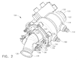
次に、図2〜図6を参照すると、バルブアセンブリ104は、第2本体120を部分的または完全に取り囲むことができる第1本体118を含む。第1本体118および第2本体120は、バルブアセンブリ104の構成要素を収容および支持するための環状構造とされる。流管122は、支持体124によって第2本体120の内部に支持される。第1本体118、第2本体120および流管122は当該技術で周知の任意の直径にすることができ、全体を通して同じ直径にしても、あるいは長さに沿って一箇所または複数箇所で変更してもよい。支持体124は、流管122が流管122を流れる流体の温度および圧力の変化によって膨張および収縮し、さらに振動の誘導負荷を支持することができるような、当該技術で周知の任意の構造にすることができる。一例示的実施形態では、支持体124は金属薄板の成形部分品であって、第1端部126が第2本体120に、第2端部127が流管122に取り付けられる。一例示的実施形態では、支持体124は2つ以上の部分品として形成してもよく、1つが第2本体120の入口側に取り付けられ、1つが第2本体120の出口側に取り付けられる。
2-6, the
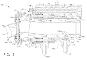
流管122は、流管122を流れる流体を受け入れるための入口130を有する入口部分128と、流管122の下流に流体を受け渡すための出口133を有する出口部分132とを含む。バルブ134は、流管122の内部に配置される。バルブ134は、当該技術で周知の任意の形式のバルブにすることができる。一例示的実施形態では、バルブ134はバタフライバルブである。バルブ134は、開放位置、閉鎖位置、およびその間のどこかに選択的に位置決めすることができる。回転軸136は、バルブ134を流管122に接続して、バルブ134を選択的に位置決めすることができる。回転軸136はバルブ134を貫通して、軸受アセンブリ138を介して流管122に接続している。回転軸136は、第1本体118および第2本体120の軸線に略垂直である。回転軸136はまた、回転軸136と平行で、第1本体118および第2本体120の中心を通過する平面からオフセットされる。
The
ピストンアセンブリ140は、回転軸136およびバルブ134を作動させるのに使用される。ピストン142は、第1本体118と第2本体120の間に配置される。作動流体をピストン142に供給するために、ポート144が第1本体118に接続される。ポート144は、流体の圧力降下が最小限に抑えられるように配置される。作動キャビティ148を密封するために、ピストン142に近接して複数のシール146が配置される。作動キャビティ148は、バルブ134を作動させるための作動流体で満たされている。ピストン142は、ピストンロッド150に接続される。このピストンロッド150の周囲に、ブッシング151が配置される。ブッシング151は、ピストンロッド150を案内および密封する。ピストン142と反対側のピストンロッド150の端部に、ピストンロッドクレビス152が配置される。ピストン142、ピストンロッド150、ブッシング151およびピストンロッドクレビス152は、第1本体118および第2本体120の軸線と平行になるように配列される。リンクアーム154は、一端がピン156によってピストンロッドクレビス152に、他端がピン157によって回転軸クランクアーム158に接続される。回転軸クランクアーム158は、回転軸136の一端に接続される。回転軸クランクアーム158は、この回転軸クランクアーム158が回転する時に回転軸136が回転するように接続される。ピストンアセンブリ140は、ピストン142の周囲のピストン力のバランスを取るように、ピストンロッド150から180度の位置に配置された第2のピストンロッド164を有する。ピストンロッド164は、上述したのと同様の構成でピストン142に接続される。ピストンロッド164には、ブッシング165、ピストンロッドクレビス166、リンクアーム168および回転軸クランクアーム170が付随する。ピストンロッド150、164は各々が、ピストン142の直線的な推進力を回転軸136の回転力に変換して、回転軸136を回転させることによって、ピストン142の運動に応じてバルブ134を開閉させることができる。
Piston
流管122は、第1屈曲部172および第2屈曲部174を含む。第1屈曲部172によって、回転軸136がピストンロッド150および164を通過する平面からオフセットされるように、回転軸136を位置決めすることができる。第2屈曲部174によって、バルブ134をピストンロッド150および164の中央に置くことができる。これにより、回転軸クランクアーム158および170をピストンロッド150および164と実質的に一直線に並べることができる。そのような構成によって、ウィッシュボーンアセンブリを必要とすることなく、回転軸136とピストンロッド150および164を直接接続することができる。
The
ピストンアセンブリ140に隣接して、センサ176が配置される。センサ176は、バルブ134の位置に関するフィードバックをエンジンに提供するために、ピストン142の位置を検出するように配置される。当該技術で周知の任意の位置センサを使用することができる。一例示的実施形態では、線形可変差動変圧器(LVDT)が使用される。センサ176は、L型ブラケット178によってピストンロッド150、162に取り付けられる。なお、センサがピストン142の位置を検出することができるのであれば、任意の取付器具を用いてもよい。
Adjacent to the
図7に示すように、使用中、流体は流管122の入口130を通って流れる(ステップ200)。流体は、第1屈曲部172において流管122の内部で方向を変える(ステップ202)。流体は、第2屈曲部174において流管122の内部で二度目に方向を変える(ステップ204)。作動流体は、ポート144から作動キャビティ148へ流れる(ステップ206)。当該技術で周知の任意の作動流体を用いることができる。作動流体によって、ピストン142はバルブ134に向かって軸方向に動かされる(ステップ208)。ピストンロッド150、164およびピストンロッドクレビス152、166もまた、ピストン142の運動に伴ってバルブ134に向かって軸方向に動くことになる(ステップ210)。直線的な推進力はさらに、リンクアーム154、168を介して回転軸クランクアーム158、170に伝達される(ステップ212)。回転軸クランクアーム158、170の直線的な推進力が回転力として回転軸136に伝達されることによって、回転軸136および付属のバルブ134が回転させられる(ステップ214)。バルブ134は、開放から閉鎖へ、閉鎖から開放へ、または中間のどこかへ切り替わるように作動する。第2のポート180が作動流体を作動キャビティ148に供給することによって、ポート144が出口として機能し、バルブ134を閉鎖する。バルブ134は、失速状態、エンジンの後方部への高圧流の再分配、燃焼器に対する入口圧力の低下、エンジンの凍結防止、翼の凍結防止、羽根先端隙間の制御、航空機の環境管理システムおよび/または補助動力装置への空気の供給、またはそれらの任意の組み合わせを含むがこれらに限定されない、さまざまな理由で作動する。初期位置は、開閉どちらでもよい。ピストン142、ピストンロッド150、ピストンロッドクレビス152、リンクアーム154および回転軸クランクアーム158が軸方向に一直線に並ぶので、回転軸およびバルブに伝達される力がより直接的でバランスの取れたものとなり、それにしたがってバルブに付加される過渡力が低下する。
As shown in FIG. 7, in use, fluid flows through the
本明細書において、本発明の例示的実施形態を、当業者による実現および活用のための最良の態様を含めて開示した。本発明の特許可能な範囲は、添付の特許請求の範囲によって定義されるとともに、当業者に想起可能なその他の実施例も包含する。かかるその他の実施例は、添付の特許請求の範囲の文言と相違ない構成要素を有する場合、または添付の特許請求の範囲の文言と実質的に相違なく同等な構成要素を含む場合、本発明の範疇にあるとみなされる。 In the present specification, exemplary embodiments of the present invention have been disclosed, including the best mode for realization and utilization by those skilled in the art. The patentable scope of the invention is defined by the appended claims, and may include other examples that occur to those skilled in the art. Such other embodiments have components that do not differ from the language of the appended claims, or include components that are substantially equivalent to the language of the appended claims. Considered to be in category.
100 ガスタービンエンジン
102 ダクト
104 バルブアセンブリ
106 圧縮機
108 燃焼器
110 タービン
112 タービン
114 ファンアセンブリ
116 過渡抽気システム
118 第1本体
120 第2本体
122 流管
124 支持体
126 第1端部
127 第2端部
128 入口部分
130 入口
132 出口部分
133 出口
134 バルブ
136 回転軸
138 軸受アセンブリ
140 ピストンアセンブリ
142 ピストン
144 ポート
146 シール
148 作動キャビティ
150 ピストンロッド
151 ブッシング
152 ピストンロッドクレビス
154 リンクアーム
156 ピン
157 ピン
158 回転軸クランクアーム
164 ピストンロッド
165 ブッシング
166 ピストンロッドクレビス
168 リンクアーム
170 回転軸クランクアーム
172 第1屈曲部
174 第2屈曲部
176 センサ
178 L型ブラケット
200 ステップ
202 ステップ
204 ステップ
206 ステップ
208 ステップ
210 ステップ
212 ステップ
214 ステップ
DESCRIPTION OF
Claims (10)
開放バルブ(134)と、第1屈曲部(172)と、第2屈曲部(174)とを有する流管(122)を設けるステップと、
前記流管(122)に流体を流すステップと、
ピストン(142)を軸方向に動くように作動させるステップと、
前記ピストン(142)の軸方向運動によって前記バルブ(134)を閉鎖するステップとを含む、流体流調整方法。 A method for regulating a fluid flow of a gas turbine engine, comprising:
Providing a flow tube (122) having an open valve (134), a first bend (172), and a second bend (174);
Flowing a fluid through the flow tube (122);
Actuating the piston (142) to move axially;
Closing the valve (134) by axial movement of the piston (142).
Applications Claiming Priority (1)
| Application Number | Priority Date | Filing Date | Title |
|---|---|---|---|
| US12/040,469 US8157241B2 (en) | 2008-02-29 | 2008-02-29 | Methods and apparatus for regulating gas turbine engine fluid flow |
Publications (1)
| Publication Number | Publication Date |
|---|---|
| JP2009209935A true JP2009209935A (en) | 2009-09-17 |
Family
ID=40637974
Family Applications (1)
| Application Number | Title | Priority Date | Filing Date |
|---|---|---|---|
| JP2009043297A Pending JP2009209935A (en) | 2008-02-29 | 2009-02-26 | Method and device for regulating fluid flow in gas turbine engine |
Country Status (4)
| Country | Link |
|---|---|
| US (1) | US8157241B2 (en) |
| EP (1) | EP2096267A3 (en) |
| JP (1) | JP2009209935A (en) |
| CN (1) | CN101520002A (en) |
Families Citing this family (9)
| Publication number | Priority date | Publication date | Assignee | Title |
|---|---|---|---|---|
| CA2712687A1 (en) * | 2009-08-12 | 2011-02-12 | R700 Holdings Ltd. | Supercharger system for two-stroke engines |
| US8613198B2 (en) * | 2009-12-23 | 2013-12-24 | Unison Industries, Llc | Method and apparatus for controlling compressor bleed airflow of a gas turbine engine using a butterfly valve assembly |
| US8464740B2 (en) * | 2011-06-13 | 2013-06-18 | Honeywell International Inc. | Combustor fuel control systems with flow divider assemblies |
| US20130104516A1 (en) * | 2011-10-31 | 2013-05-02 | General Electric Company | Method of monitoring an operation of a compressor bleed valve |
| USD753726S1 (en) * | 2014-11-05 | 2016-04-12 | Chandler Fitzgerald | Throttle body coupler |
| US10408218B2 (en) | 2016-11-21 | 2019-09-10 | Ge Aviation Systems Llc | Fan with shut-off valve and method of operating |
| US9958071B1 (en) | 2017-02-15 | 2018-05-01 | Hamilton Sundstrand Corporation | High temperature shaft seal for bleed valve with roller bearings |
| CN109882600A (en) * | 2019-04-08 | 2019-06-14 | 河南天利热工装备股份有限公司 | A kind of flat-pushing air valve of multistation |
| CN113738453B (en) * | 2021-11-08 | 2022-02-01 | 中国航发四川燃气涡轮研究院 | Turbine guide vane cooling air flow adjusting device |
Citations (4)
| Publication number | Priority date | Publication date | Assignee | Title |
|---|---|---|---|---|
| US4576358A (en) * | 1983-04-20 | 1986-03-18 | Hydril Company | Remotely operable safety valve |
| US5445248A (en) * | 1994-03-07 | 1995-08-29 | Jenara Enterprises Ltd. | Exhaust brake |
| JPH10205643A (en) * | 1997-01-20 | 1998-08-04 | Kobe Steel Ltd | Opening control device for pipe passage opening/closing mechanism |
| US20040074237A1 (en) * | 2002-10-17 | 2004-04-22 | Swinford Mark Douglas | Methods and apparatus for regulating gas turbine engine fluid flow |
Family Cites Families (23)
| Publication number | Priority date | Publication date | Assignee | Title |
|---|---|---|---|---|
| US2934084A (en) * | 1954-04-12 | 1960-04-26 | Boeing Co | Butterfly check valves |
| US3108767A (en) * | 1960-03-14 | 1963-10-29 | Rolls Royce | By-pass gas turbine engine with air bleed means |
| US3107892A (en) * | 1960-12-01 | 1963-10-22 | Gen Motors Corp | Compressor air bleed valve |
| US3539147A (en) * | 1969-01-21 | 1970-11-10 | Herman L Paul Jr | Power actuated ball valve |
| US3545486A (en) * | 1969-01-31 | 1970-12-08 | Holley Carburetor Co | In-line valving assembly |
| US3690615A (en) * | 1970-07-24 | 1972-09-12 | Stile Craft Mfg Inc | Automatic valve |
| DE2102441C3 (en) * | 1971-01-20 | 1975-06-12 | H. Kuhnke Elektrotechnische Fabrik Gmbh, 2427 Malente | Timing element for binary pneumatic signals |
| AT324061B (en) * | 1972-04-27 | 1975-08-11 | Ecpp & Reuter Gmbh | BUTTERFLY VALVE |
| GB1463697A (en) * | 1973-06-15 | 1977-02-02 | Pont A Mousson | Flow regulating valve |
| US3892381A (en) * | 1973-10-23 | 1975-07-01 | Atwood & Morrill Co Inc | Fail-safe valve |
| CA1034107A (en) * | 1975-02-11 | 1978-07-04 | Edward B. Myers | Rotary valve |
| FR2308792A2 (en) * | 1975-04-24 | 1976-11-19 | France Etat | IMPROVEMENTS TO INSTALLATIONS WITH SUPERCHARGED INTERNAL COMBUSTION ENGINE, ESPECIALLY WITH SUPERCHARGED DIESEL ENGINE |
| US4111166A (en) * | 1977-02-07 | 1978-09-05 | Caterpillar Tractor Co. | Engine mounted exhaust brake |
| US4353390A (en) * | 1979-12-06 | 1982-10-12 | Anchor/Darling Valve Company | Swing check valve with internally balanced disc |
| US4299373A (en) * | 1980-01-28 | 1981-11-10 | Ranco Incorporated | Fluid flow control valve |
| GB9024644D0 (en) * | 1990-11-13 | 1991-01-02 | Dewandre Co Ltd C | An exhaust brake |
| US5355673A (en) * | 1992-11-18 | 1994-10-18 | Sterling Robert E | Exhaust valve |
| US5392812A (en) * | 1992-12-04 | 1995-02-28 | General Electric Company | Offset hinge flapper valve |
| JP2606154Y2 (en) * | 1993-01-27 | 2000-09-25 | ボッシュ ブレーキ システム株式会社 | Butterfly valve |
| US5676110A (en) * | 1996-03-14 | 1997-10-14 | Meneely; Vincent Allan | Exhaust brake with offset butterfly and method of reducing back pressure therein |
| US6283448B1 (en) * | 2000-04-19 | 2001-09-04 | Daniel Webster Denton | Offset butterfly valve |
| US6722137B2 (en) * | 2001-08-17 | 2004-04-20 | General Electric Co. | Methods and apparatus for regulating turbine clearance control system airflow |
| US7484710B2 (en) * | 2002-03-19 | 2009-02-03 | Fisher Controls International Llc | Fluid flow control valve with high temperature bi-directional shutoff |
-
2008
- 2008-02-29 US US12/040,469 patent/US8157241B2/en active Active
-
2009
- 2009-02-17 EP EP20090153053 patent/EP2096267A3/en not_active Withdrawn
- 2009-02-26 JP JP2009043297A patent/JP2009209935A/en active Pending
- 2009-02-27 CN CN200910118440A patent/CN101520002A/en active Pending
Patent Citations (5)
| Publication number | Priority date | Publication date | Assignee | Title |
|---|---|---|---|---|
| US4576358A (en) * | 1983-04-20 | 1986-03-18 | Hydril Company | Remotely operable safety valve |
| US5445248A (en) * | 1994-03-07 | 1995-08-29 | Jenara Enterprises Ltd. | Exhaust brake |
| JPH10205643A (en) * | 1997-01-20 | 1998-08-04 | Kobe Steel Ltd | Opening control device for pipe passage opening/closing mechanism |
| US20040074237A1 (en) * | 2002-10-17 | 2004-04-22 | Swinford Mark Douglas | Methods and apparatus for regulating gas turbine engine fluid flow |
| JP2004138065A (en) * | 2002-10-17 | 2004-05-13 | General Electric Co <Ge> | Method and device for adjusting fluid flow of gas turbine engine |
Also Published As
| Publication number | Publication date |
|---|---|
| EP2096267A2 (en) | 2009-09-02 |
| CN101520002A (en) | 2009-09-02 |
| US8157241B2 (en) | 2012-04-17 |
| US20090217987A1 (en) | 2009-09-03 |
| EP2096267A3 (en) | 2013-06-12 |
Similar Documents
| Publication | Publication Date | Title |
|---|---|---|
| JP2009209934A (en) | Method and device for regulating fluid flow in gas turbine engine | |
| JP2009209935A (en) | Method and device for regulating fluid flow in gas turbine engine | |
| JP2011132960A (en) | Method and apparatus for controlling fluid flow | |
| JP5522949B2 (en) | Multi-flow turbojet engine installation on aircraft | |
| US20140314549A1 (en) | Flow manipulating arrangement for a turbine exhaust diffuser | |
| US8579579B2 (en) | Sealed shaft assembly for exhaust turbines | |
| US11105338B2 (en) | Impeller shroud with slidable coupling for clearance control in a centrifugal compressor | |
| US7393179B1 (en) | Variable position turbine nozzle | |
| US11002284B2 (en) | Impeller shroud with thermal actuator for clearance control in a centrifugal compressor | |
| JP4355915B2 (en) | Method and apparatus for regulating fluid flow in a gas turbine engine | |
| JP2011208637A (en) | System and method for exhaust diffuser | |
| GB2276423A (en) | Guide vane adjustment in radial-flow exhaust turbocharger turbine | |
| GB2470586A (en) | Eccentric joint for actuator connection rod. | |
| US8347601B2 (en) | Device for pivoting at least one pivotable element in a gas turbine engine | |
| US7866228B2 (en) | Device for moving at least one moveable element in a gas turbine | |
| US10648359B2 (en) | System for controlling variable-setting blades for a turbine engine | |
| US10920671B2 (en) | Thrust balance control with differential power extraction | |
| JPS6375398A (en) | Fixing angle varying device for stationary blade |
Legal Events
| Date | Code | Title | Description |
|---|---|---|---|
| A621 | Written request for application examination |
Free format text: JAPANESE INTERMEDIATE CODE: A621 Effective date: 20120221 |
|
| A977 | Report on retrieval |
Free format text: JAPANESE INTERMEDIATE CODE: A971007 Effective date: 20121225 |
|
| A131 | Notification of reasons for refusal |
Free format text: JAPANESE INTERMEDIATE CODE: A131 Effective date: 20130108 |
|
| A601 | Written request for extension of time |
Free format text: JAPANESE INTERMEDIATE CODE: A601 Effective date: 20130405 |
|
| RD04 | Notification of resignation of power of attorney |
Free format text: JAPANESE INTERMEDIATE CODE: A7424 Effective date: 20130405 |
|
| A602 | Written permission of extension of time |
Free format text: JAPANESE INTERMEDIATE CODE: A602 Effective date: 20130417 |
|
| A521 | Request for written amendment filed |
Free format text: JAPANESE INTERMEDIATE CODE: A523 Effective date: 20130708 |
|
| A02 | Decision of refusal |
Free format text: JAPANESE INTERMEDIATE CODE: A02 Effective date: 20131203 |