JP2009204302A - Combustor fuel nozzle structure - Google Patents
Combustor fuel nozzle structure Download PDFInfo
- Publication number
- JP2009204302A JP2009204302A JP2009030819A JP2009030819A JP2009204302A JP 2009204302 A JP2009204302 A JP 2009204302A JP 2009030819 A JP2009030819 A JP 2009030819A JP 2009030819 A JP2009030819 A JP 2009030819A JP 2009204302 A JP2009204302 A JP 2009204302A
- Authority
- JP
- Japan
- Prior art keywords
- tube
- feed pipe
- section
- fuel nozzle
- tip
- Prior art date
- Legal status (The legal status is an assumption and is not a legal conclusion. Google has not performed a legal analysis and makes no representation as to the accuracy of the status listed.)
- Pending
Links
Images


Classifications
-
- F—MECHANICAL ENGINEERING; LIGHTING; HEATING; WEAPONS; BLASTING
- F23—COMBUSTION APPARATUS; COMBUSTION PROCESSES
- F23R—GENERATING COMBUSTION PRODUCTS OF HIGH PRESSURE OR HIGH VELOCITY, e.g. GAS-TURBINE COMBUSTION CHAMBERS
- F23R3/00—Continuous combustion chambers using liquid or gaseous fuel
- F23R3/28—Continuous combustion chambers using liquid or gaseous fuel characterised by the fuel supply
-
- F—MECHANICAL ENGINEERING; LIGHTING; HEATING; WEAPONS; BLASTING
- F23—COMBUSTION APPARATUS; COMBUSTION PROCESSES
- F23D—BURNERS
- F23D11/00—Burners using a direct spraying action of liquid droplets or vaporised liquid into the combustion space
- F23D11/36—Details, e.g. burner cooling means, noise reduction means
- F23D11/38—Nozzles; Cleaning devices therefor
-
- F—MECHANICAL ENGINEERING; LIGHTING; HEATING; WEAPONS; BLASTING
- F23—COMBUSTION APPARATUS; COMBUSTION PROCESSES
- F23D—BURNERS
- F23D2211/00—Thermal dilatation prevention or compensation
-
- F—MECHANICAL ENGINEERING; LIGHTING; HEATING; WEAPONS; BLASTING
- F23—COMBUSTION APPARATUS; COMBUSTION PROCESSES
- F23R—GENERATING COMBUSTION PRODUCTS OF HIGH PRESSURE OR HIGH VELOCITY, e.g. GAS-TURBINE COMBUSTION CHAMBERS
- F23R2900/00—Special features of, or arrangements for continuous combustion chambers; Combustion processes therefor
- F23R2900/00001—Arrangements using bellows, e.g. to adjust volumes or reduce thermal stresses
Landscapes
- Engineering & Computer Science (AREA)
- Chemical & Material Sciences (AREA)
- Combustion & Propulsion (AREA)
- Mechanical Engineering (AREA)
- General Engineering & Computer Science (AREA)
- Pressure-Spray And Ultrasonic-Wave- Spray Burners (AREA)
- Nozzles For Spraying Of Liquid Fuel (AREA)
Abstract
Description
本発明は、燃焼器に関する。より具体的には、本発明は、燃焼器燃料ノズルの送油管及び送水管に関する。 The present invention relates to a combustor. More specifically, the present invention relates to an oil feed pipe and a water feed pipe of a combustor fuel nozzle.
ガスタービンの燃焼器は一般的に、燃料が送給され燃焼器の燃焼領域に燃料を噴射する1以上の燃料ノズルを含む。水及び燃料は、それぞれ送水管及び送油管から燃焼ゾーンに噴射されることが多い。多くのノズルの構成において、送油管は、送水管の内部に設置され、送水管及び送油管は共に先端部に連結される。燃焼ダイナミックス及び送油管と送水管の間の熱負荷差のため、燃焼器作動時に送油管と送水管の間に偏心が生じる。さらに、送油管は、燃焼器作動時に振動周波数によって影響を受けて、送油管上に高い振動応力が生じ、そのため送油管の磨耗を増大させかつ送油管の有効寿命を低下させることが多い。 Gas turbine combustors typically include one or more fuel nozzles that are supplied with fuel and inject fuel into the combustion region of the combustor. Water and fuel are often injected into the combustion zone from water and oil pipes, respectively. In many nozzle configurations, the oil feed pipe is installed inside the water feed pipe, and the water feed pipe and the oil feed pipe are both connected to the tip. Due to the combustion dynamics and the difference in heat load between the oil feed pipe and the water feed pipe, eccentricity occurs between the oil feed pipe and the water feed pipe when the combustor is operated. In addition, oil pipes are affected by the vibration frequency during operation of the combustor, resulting in high vibration stress on the oil pipe, thereby increasing wear on the oil pipe and reducing the useful life of the oil pipe.
燃焼器用の燃料ノズルは、先端部セクションと管セクションとを含む。内部で第1の端部が先端部セクションと連結する管セクションは、管軸線を有しかつ先端部セクションに連結した外管と、外管の内部に少なくとも部分的に配置されかつ先端部セクションに連結した内管とを含む。内管は、本燃料ノズル内での応力を低減することができる1以上の可撓性部分を含む。 A fuel nozzle for a combustor includes a tip section and a tube section. A tube section having a first end connected to the tip section therein has an outer tube having a tube axis and connected to the tip section, and at least partially disposed within the outer tube and connected to the tip section. And connected inner pipes. The inner tube includes one or more flexible portions that can reduce stress within the fuel nozzle.
燃料ノズルの第2の実施形態は、先端部セクションと、基部セクションと、先端部セクションと基部セクションの間に配置されかつ第1の端部で先端部セクションに連結しているとともに第2の端部で基部セクションに連結した管セクションとを含む。管セクションは、管軸線を有する外管と、外管の内部に少なくとも部分的に配置されかつ先端部セクションに連結した内管とを含む。1以上のリブが、外管上に配置されかつ外管の外面から半径方向外向きに延びる。 A second embodiment of the fuel nozzle includes a tip section, a base section, a tip section disposed between the tip section and the base section and coupled to the tip section at a first end and a second end. And a tube section connected to the base section at the section. The tube section includes an outer tube having a tube axis, and an inner tube disposed at least partially within the outer tube and connected to the tip section. One or more ribs are disposed on the outer tube and extend radially outward from the outer surface of the outer tube.
これらの及びその他の利点及び特徴は、図面と関連させてなした以下の説明から一層明らかになるであろう。 These and other advantages and features will become more apparent from the following description taken in conjunction with the drawings.
本発明と見なされる主題は、本明細書と共に提出した特許請求の範囲において具体的に指摘しかつ明確に特許請求している。本発明の前述の及びその他の目的、特徴及び利点は、添付図面と関連させてなした以下の詳細な説明から明らかとなる。 The subject matter regarded as the invention is particularly pointed out and distinctly claimed in the claims appended hereto. The foregoing and other objects, features and advantages of the present invention will become apparent from the following detailed description, taken in conjunction with the accompanying drawings.
詳細な説明では、図面を参照して実施例によって、本発明の実施形態を利点及び特徴と共に説明する。 The detailed description explains embodiments of the invention, together with advantages and features, by way of example with reference to the drawings.
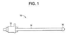
図1に示すのは、改良型の燃料ノズル10の実施形態である。この燃料ノズル10は、基部12と基部12から先端部16まで延びる管セクション14とを含む。図2に示すように、幾つかの実施形態では、基部12は、それを通して管セクション14が挿入されかつ燃料源(図示せず)に連結して管セクション14に燃料を供給するボア18を含む。管セクション14は、送水管22内に配置された送油管20を含む。図2に示す実施形態では、送油管20及び送水管22は各々、円形断面を有するが、燃焼器の作動要件に応じて利用することができる長円形を含むその他の断面も、本発明の技術的範囲内で考えられる。幾つかの実施形態では、送油管20は、管軸線24の周りで送水管22と同心である。管セクションはさらに、送水管22に対して同心の又は同心でない所望の半径方向位置に送油管20を保持する1以上のスペーサ26を含むことができる。スペーサ26は、図2の実施形態におけるようにその断面を完全な環状とすることができ、或いはそれに代えて、送油管20と送水管22との間に配置されたセグメントで製作しまた貫通孔(図示せず)又はその他の手段で構成して、送水管22内の水の流れがスペーサ26の第1の側面からスペーサ26の第2の側面に流れるのを可能にすることができる。スペーサ26は、例えばロウ付けによって送油管20及び送水管22のいずれか又は両方に連結することができる。
Illustrated in FIG. 1 is an embodiment of an improved
図3に示すように、送油管20は、1以上の可撓性部分、すなわちこの実施形態ではベローズ34によって連結された少なくとも第1の送油管部分30及び第2の送油管部分32を含む。ベローズ34は、外径38及び内径40を有する1以上の回旋部36を含みかつ第1の端部42で第1の送油管部分30に連結しているとともに第2の端部44で第2の送油管部分32に連結する。ベローズ34は、例えばロウ付けによって第1の送油管部分30及び第2の送油管部分32に連結することができ、或いは幾つかの実施形態では、第1の送油管部分30及び第2の送油管部分32のいずれか又は両方と一体形に形成することができる。図3に示す実施形態は、単一のベローズ34を有する送油管20を含むが、これ以外のベローズ34の数量、例えば2つ又は3つのベローズ34も、本発明の技術的範囲内で考えられる。
As shown in FIG. 3, the
図4に示すように、先端部16は、管セクション14の一方の端部に連結し、送油管20と同心でありかつ送油管20を液体燃料スワーラ48に連結する環状の管アダプタ46を含むことができる。送油管20と管アダプタ46との間の連結及び管アダプタ46と液体燃料スワーラ48との間の連結は、ロウ付けによって達成することができる。液体燃料スワーラ48と同心になっているのは、空気−燃料スワーラ50であり、この空気−燃料スワーラ50は、一方の端部で送水管22に連結しているとともにスワーラランド部52で液体燃料スワーラ48に連結している。最終的に、空気−燃料スワーラ48から半径方向外側寄りに配置されかつ例えばロウ付けによってノズルランド部56において空気−燃料スワーラ48に取付けられたシュラウド54を含むことができる。ベローズ34により、燃焼器の作動時に送油管20が送水管22及び先端部16に対して熱膨張及び熱収縮することが可能になり、それにより、送油管20及び送水管22と先端部16との間の応力を減少させまたノズル10の有効寿命を延ばすことが可能になる。
As shown in FIG. 4, the
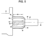
図5に示すように、幾つかの実施形態では、送水管22は、送水管22の外面60から外向きに延びる複数のリブ58を含む。リブ58は、幾つかの実施形態では約350Hzである、燃焼器の振動周波数から離れるように送水管22の固有振動数を偏移させるように構成されかつ設置される。図5に示すリブ58は、送水管22の基部端部62に設置される。この実施形態のリブ58は、ほぼ管軸線24に沿って整列しておりかつ送水管22の外面60からほぼ半径方向に延びる。さらに、図5に示すリブ58は、リブ58の軸方向長さ64がリブ先端部68における軸方向長さ64よりもリブ基部66においてより長くなるようにテーパしている。図5に示すリブ58の位置、配置及び構成は、単なる例示的なものに過ぎず、送水管22の固有振動数を偏移させるようなリブ58のその他の位置、配置及び構成も、本発明の技術的範囲内で考えられる。
As shown in FIG. 5, in some embodiments, the
限られた数の実施形態のみに関して本発明を詳細に説明してきたが、本発明が、そのような開示した実施形態に限定されるものではないことは容易に解る筈である。むしろ、本発明は、今まで説明していないが本発明の技術思想及び技術的範囲に相応するあらゆる数の変形形態、変更形態、置換形態、或いは均等な構成を組込むように修正することができる。さらに、本発明の様々な実施形態について説明してきたが、本発明の態様は説明した実施形態の幾つかだけを含むことができることを理解されたい。従って、本発明は、前記の説明によって限定されるものと見なすべきではなく、特許請求の範囲の技術的範囲によってのみ限定される。 Although the present invention has been described in detail with respect to only a limited number of embodiments, it should be readily understood that the invention is not limited to such disclosed embodiments. Rather, the invention can be modified to incorporate any number of variations, alterations, substitutions or equivalent arrangements not heretofore described, but which are commensurate with the spirit and scope of the invention. . Moreover, while various embodiments of the invention have been described, it is to be understood that aspects of the invention can include only some of the described embodiments. Accordingly, the invention is not to be seen as limited by the foregoing description, but is only limited by the scope of the claims.
10 燃料ノズル
12 基部
14 管セクション
16 先端部
18 ボア
20 送油管
22 送水管
24 管軸線
26 スペーサ
30 第1の送油管部分
32 第2の送油管部分
34 ベローズ
36 回旋部
38 外径
40 内径
42 第1の端部
44 第2の端部
46 管アダプタ
48 燃料スワーラ
50 空気−燃料スワーラ
52 スワーラランド部
54 シュラウド
56 ノズルランド部
58 リブ
60 外面
62 基部端部
64 軸方向長さ
66 リブ基部
68 リブ先端部
DESCRIPTION OF
Claims (10)
先端部(16)セクションと、
前記先端部(16)セクションに連結した第1の端部(42)を有する管セクション(14)と、
を含み、前記管セクション(14)が、
管軸線(24)を有しかつ前記先端部(16)セクションに連結した外管(22)と、
前記外管(22)の内部に少なくとも部分的に配置されかつ前記先端部(16)セクションに連結した内管(20)と、を含み、
前記内管(20)が、燃料ノズル(10)内の応力を減少させるようになった1以上の可撓性部分を有する、
燃料ノズル(10)。 A fuel nozzle (10) for a combustor,
A tip (16) section;
A tube section (14) having a first end (42) coupled to the tip (16) section;
Said tube section (14) comprising:
An outer tube (22) having a tube axis (24) and connected to the tip (16) section;
An inner tube (20) disposed at least partially within the outer tube (22) and connected to the tip (16) section;
The inner tube (20) has one or more flexible portions adapted to reduce stress in the fuel nozzle (10);
Fuel nozzle (10).
先端部(16)セクションと、
基部(12)セクションと、
前記先端部(16)セクションと基部(12)セクションの間に配置されかつ第1の端部(42)で先端部(16)セクションに連結しているとともに第2の端部(44)で基部(12)セクションに連結した管セクション(14)と、
を含み、前記管セクション(14)が、
管軸線(24)を有する外管(22)と、
前記外管(22)の内部に少なくとも部分的に配置されかつ前記先端部(16)セクションに連結した内管(20)と、
前記外管(22)と動作可能な連動状態で配置されかつ外管(22)の外面(60)から半径方向外向きに延びる1以上のリブ(58)と、を含む、
燃料ノズル(10)。 A fuel nozzle (10) for a combustor,
A tip (16) section;
A base (12) section;
Located between the tip (16) section and the base (12) section and connected to the tip (16) section at the first end (42) and at the second end (44) (12) a tube section (14) connected to the section;
Said tube section (14) comprising:
An outer tube (22) having a tube axis (24);
An inner tube (20) disposed at least partially within the outer tube (22) and connected to the tip (16) section;
One or more ribs (58) disposed in operable linkage with the outer tube (22) and extending radially outward from an outer surface (60) of the outer tube (22);
Fuel nozzle (10).
Applications Claiming Priority (1)
| Application Number | Priority Date | Filing Date | Title |
|---|---|---|---|
| US12/038,869 US20090218421A1 (en) | 2008-02-28 | 2008-02-28 | Combustor fuel nozzle construction |
Publications (1)
| Publication Number | Publication Date |
|---|---|
| JP2009204302A true JP2009204302A (en) | 2009-09-10 |
Family
ID=40936469
Family Applications (1)
| Application Number | Title | Priority Date | Filing Date |
|---|---|---|---|
| JP2009030819A Pending JP2009204302A (en) | 2008-02-28 | 2009-02-13 | Combustor fuel nozzle structure |
Country Status (5)
| Country | Link |
|---|---|
| US (1) | US20090218421A1 (en) |
| JP (1) | JP2009204302A (en) |
| CN (1) | CN101526214B (en) |
| CH (1) | CH698570B1 (en) |
| DE (1) | DE102009003525A1 (en) |
Families Citing this family (9)
| Publication number | Priority date | Publication date | Assignee | Title |
|---|---|---|---|---|
| CN101737804B (en) * | 2009-12-08 | 2012-02-22 | 沈阳黎明航空发动机(集团)有限责任公司 | Oil-water gas nozzle for heavy type combustion engine |
| WO2015076692A1 (en) * | 2013-11-22 | 2015-05-28 | General Electric Company | Fuel nozzle cartridge and method for assembly |
| US9803555B2 (en) * | 2014-04-23 | 2017-10-31 | General Electric Company | Fuel delivery system with moveably attached fuel tube |
| US10203114B2 (en) | 2016-03-04 | 2019-02-12 | General Electric Company | Sleeve assemblies and methods of fabricating same |
| US10228141B2 (en) * | 2016-03-04 | 2019-03-12 | General Electric Company | Fuel supply conduit assemblies |
| US10612784B2 (en) | 2017-06-19 | 2020-04-07 | General Electric Company | Nozzle assembly for a dual-fuel fuel nozzle |
| US10955141B2 (en) | 2017-06-19 | 2021-03-23 | General Electric Company | Dual-fuel fuel nozzle with gas and liquid fuel capability |
| US10612775B2 (en) | 2017-06-19 | 2020-04-07 | General Electric Company | Dual-fuel fuel nozzle with air shield |
| US10663171B2 (en) | 2017-06-19 | 2020-05-26 | General Electric Company | Dual-fuel fuel nozzle with gas and liquid fuel capability |
Citations (7)
| Publication number | Priority date | Publication date | Assignee | Title |
|---|---|---|---|---|
| US4258544A (en) * | 1978-09-15 | 1981-03-31 | Caterpillar Tractor Co. | Dual fluid fuel nozzle |
| JP2587576B2 (en) * | 1992-08-21 | 1997-03-05 | ウエスチングハウス・エレクトリック・コーポレイション | Method of manufacturing fuel nozzle assembly for gas turbine and method of replacing nozzle cap in fuel nozzle assembly |
| JPH1019258A (en) * | 1996-03-29 | 1998-01-23 | General Electric Co <Ge> | Diffusion/premixing nozzle for gas turbine combustor |
| JP2000039147A (en) * | 1998-07-21 | 2000-02-08 | Mitsubishi Heavy Ind Ltd | Pilot nozzle for combustor equipped with flexible joint |
| US6276141B1 (en) * | 1996-03-13 | 2001-08-21 | Parker-Hannifin Corporation | Internally heatshielded nozzle |
| JP2007183090A (en) * | 2006-01-04 | 2007-07-19 | General Electric Co <Ge> | Combustion turbine engine and fuel nozzle assembly for the same |
| JP2007309641A (en) * | 2006-05-19 | 2007-11-29 | Delavan Inc | Device and method for compensating differential thermal expansion of injector component |
Family Cites Families (9)
| Publication number | Priority date | Publication date | Assignee | Title |
|---|---|---|---|---|
| US1296709A (en) * | 1917-09-06 | 1919-03-11 | Marcus C Steese | Hydrocarbon-burner. |
| US1835723A (en) * | 1930-08-15 | 1931-12-08 | Lawrence C Salzer | Blowtorch |
| US2165357A (en) * | 1938-10-14 | 1939-07-11 | George W Emmert | Vent tube for fuel tanks |
| US3615053A (en) * | 1970-06-16 | 1971-10-26 | Bethlehem Steel Corp | Gas pressure regulated atomizer tip for gas/oil burner |
| US3915382A (en) * | 1974-04-29 | 1975-10-28 | J C Davis | Extension spray gun |
| IT206208Z2 (en) * | 1985-11-15 | 1987-07-13 | Italiana Serrature Torino | FUEL SUPPLEMENT BODY FOR VEHICLES |
| US5156191A (en) * | 1986-09-29 | 1992-10-20 | Dayco Products, Inc. | Hose assembly having a spider-like member holding the ends of inner and outer hoses thereof concentric and method of making the same |
| US4854349A (en) * | 1987-04-28 | 1989-08-08 | Dennis Foreman | Sewage draining device for recreational vehicles or the like |
| US6076356A (en) * | 1996-03-13 | 2000-06-20 | Parker-Hannifin Corporation | Internally heatshielded nozzle |
-
2008
- 2008-02-28 US US12/038,869 patent/US20090218421A1/en not_active Abandoned
-
2009
- 2009-02-13 JP JP2009030819A patent/JP2009204302A/en active Pending
- 2009-02-20 CN CN2009100080630A patent/CN101526214B/en not_active Expired - Fee Related
- 2009-02-23 CH CH00269/09A patent/CH698570B1/en not_active IP Right Cessation
- 2009-02-23 DE DE102009003525A patent/DE102009003525A1/en not_active Withdrawn
Patent Citations (7)
| Publication number | Priority date | Publication date | Assignee | Title |
|---|---|---|---|---|
| US4258544A (en) * | 1978-09-15 | 1981-03-31 | Caterpillar Tractor Co. | Dual fluid fuel nozzle |
| JP2587576B2 (en) * | 1992-08-21 | 1997-03-05 | ウエスチングハウス・エレクトリック・コーポレイション | Method of manufacturing fuel nozzle assembly for gas turbine and method of replacing nozzle cap in fuel nozzle assembly |
| US6276141B1 (en) * | 1996-03-13 | 2001-08-21 | Parker-Hannifin Corporation | Internally heatshielded nozzle |
| JPH1019258A (en) * | 1996-03-29 | 1998-01-23 | General Electric Co <Ge> | Diffusion/premixing nozzle for gas turbine combustor |
| JP2000039147A (en) * | 1998-07-21 | 2000-02-08 | Mitsubishi Heavy Ind Ltd | Pilot nozzle for combustor equipped with flexible joint |
| JP2007183090A (en) * | 2006-01-04 | 2007-07-19 | General Electric Co <Ge> | Combustion turbine engine and fuel nozzle assembly for the same |
| JP2007309641A (en) * | 2006-05-19 | 2007-11-29 | Delavan Inc | Device and method for compensating differential thermal expansion of injector component |
Also Published As
| Publication number | Publication date |
|---|---|
| DE102009003525A1 (en) | 2009-09-10 |
| CN101526214B (en) | 2012-06-27 |
| CH698570B1 (en) | 2013-11-29 |
| CH698570A2 (en) | 2009-08-31 |
| US20090218421A1 (en) | 2009-09-03 |
| CN101526214A (en) | 2009-09-09 |
Similar Documents
| Publication | Publication Date | Title |
|---|---|---|
| JP2009204302A (en) | Combustor fuel nozzle structure | |
| JP4764391B2 (en) | Gas turbine combustor | |
| JP4818895B2 (en) | Fuel mixture injection device, combustion chamber and turbine engine equipped with such device | |
| JP5911672B2 (en) | Combustor liner for turbine engines | |
| US7448215B2 (en) | Combustion chamber for a gas turbine engine | |
| EP2851619B1 (en) | Dual-fuel burning gas turbine combustor | |
| JP5639516B2 (en) | Segmented annular ring manifold quaternary fuel distributor | |
| JP5960968B2 (en) | Premix nozzle | |
| US20100071663A1 (en) | External rigid fuel manifold | |
| JP2009156542A (en) | Burner for gas turbine | |
| JP2009250242A (en) | Combustor seal having multiple cooling fluid pathways | |
| JP2007010305A (en) | Turbine engine augmentor, use of electro-graphitic carbon material, and method of modifying turbine engine augmentor or configuration of augmentor | |
| JP2012098022A5 (en) | ||
| JP4948752B2 (en) | Full port type external gimbal fitting | |
| US20120036859A1 (en) | Combustor transition piece with dilution sleeves and related method | |
| US20140245746A1 (en) | Combustion arrangement and method of reducing pressure fluctuations of a combustion arrangement | |
| JP2008122068A (en) | Combustor dome mixer retaining means | |
| JP2011038766A (en) | Integral liner and venturi for eliminating air leakage | |
| JP2010112701A (en) | Fuel nozzle assembly used in gas turbine engine and method of assembling the same | |
| JP2015535050A (en) | Holder for exhaust pipe in turbomachine | |
| JP2011085383A (en) | High strength crossover manifold and joining method | |
| JP5558168B2 (en) | Combustor and gas turbine | |
| JP5603718B2 (en) | Circumferential self-expanding support for turbine engines | |
| KR101898402B1 (en) | Combustor and gas turbine comprising same | |
| JP2013151934A (en) | Turbine exhaust diffuser system |
Legal Events
| Date | Code | Title | Description |
|---|---|---|---|
| RD04 | Notification of resignation of power of attorney |
Free format text: JAPANESE INTERMEDIATE CODE: A7424 Effective date: 20110218 |
|
| A621 | Written request for application examination |
Free format text: JAPANESE INTERMEDIATE CODE: A621 Effective date: 20120202 |
|
| A521 | Written amendment |
Free format text: JAPANESE INTERMEDIATE CODE: A523 Effective date: 20130122 |
|
| A131 | Notification of reasons for refusal |
Free format text: JAPANESE INTERMEDIATE CODE: A131 Effective date: 20130326 |
|
| A601 | Written request for extension of time |
Free format text: JAPANESE INTERMEDIATE CODE: A601 Effective date: 20130626 |
|
| A602 | Written permission of extension of time |
Free format text: JAPANESE INTERMEDIATE CODE: A602 Effective date: 20130701 |
|
| A02 | Decision of refusal |
Free format text: JAPANESE INTERMEDIATE CODE: A02 Effective date: 20131008 |