JP2009203033A - Container conveying system - Google Patents
Container conveying system Download PDFInfo
- Publication number
- JP2009203033A JP2009203033A JP2008048218A JP2008048218A JP2009203033A JP 2009203033 A JP2009203033 A JP 2009203033A JP 2008048218 A JP2008048218 A JP 2008048218A JP 2008048218 A JP2008048218 A JP 2008048218A JP 2009203033 A JP2009203033 A JP 2009203033A
- Authority
- JP
- Japan
- Prior art keywords
- container
- rotating belts
- belts
- rotating
- predetermined
- Prior art date
- Legal status (The legal status is an assumption and is not a legal conclusion. Google has not performed a legal analysis and makes no representation as to the accuracy of the status listed.)
- Granted
Links
Images


Abstract
Description
本発明は、容器搬送システムに係り、特に容器搬送路に沿って容器を搬送中に一時的に容器の搬送を停止することができる容器搬送システムに関する。 The present invention relates to a container transport system, and more particularly to a container transport system capable of temporarily stopping transport of a container while transporting a container along a container transport path.
胴部から上向きに首部を形成したボトルに筒状ラベルあるいはキャップを被せるために、ボトルをコンベヤ装置で搬送し、一時停止させてそこで筒状ラベル等を被せることが行われている。この場合に、ボトルの位置がふらつくことを防止するため、コンベア装置等の搬送装置に工夫がされる。例えば、搬送方向に沿って旋回の向きを相互に反対とした一対のタイミングスクリューを配置し、相互に反対向きに駆動回転することで向かい合った螺旋溝の間にボトルを挟んで搬送する方式においては、螺旋溝のリード角がない部分を設け、そこを停留部として、ボトルの搬送の進行を一時的に停留させることが行われる。 In order to put a cylindrical label or a cap on a bottle having a neck formed upward from the trunk, the bottle is transported by a conveyor device, temporarily stopped, and covered with a cylindrical label or the like. In this case, in order to prevent the bottle position from fluctuating, a device such as a conveyor device is devised. For example, in a system in which a pair of timing screws whose directions of turning are opposite to each other along the conveying direction are arranged and a bottle is sandwiched between spiral grooves facing each other by driving and rotating in opposite directions to each other, A portion having no lead angle of the spiral groove is provided, and this is used as a stopping part to temporarily stop the progress of the bottle conveyance.
このタイミングスクリュー搬送方式における停留部で筒状ラベル等を被せる場合、ボトルは向かい合う螺旋溝の間で挟持されているので、筒状ラベル等を被せる首部の位置がふらつくことがある。 When a cylindrical label or the like is put on the stationary part in this timing screw conveyance system, the bottle is sandwiched between the spiral grooves facing each other, so that the position of the neck that puts the cylindrical label or the like may fluctuate.
そのために、特許文献1には、ボトルの胴部が停留部に進入してきたとき、ボトルの首部を挟持すると共に、ボトルの胴部が停留部を脱するときボトルの首部を開放する保持手段を設けることが開示されている。 For this purpose, Patent Document 1 includes a holding means for holding the neck of the bottle when the body of the bottle enters the stop, and opening the neck of the bottle when the body of the bottle is removed from the stop. Providing is disclosed.
上記特許文献1の方法によれば、搬送する対象である容器であるボトルの寸法等が変更になると、タイミングスクリューの取替えとともに、保持手段の取替えが必要になることがある。 According to the method disclosed in Patent Document 1, when the size of a bottle that is a container to be transported is changed, it may be necessary to replace the holding means as well as the timing screw.
本発明の目的は、搬送する対象の容器をしっかりと保持できる停留装置を備える容器搬送システムを提供することである。また、他の目的は、搬送する対象である容器の変更に柔軟に対応可能な停留装置を備える容器搬送システムを提供することである。以下の手段は、上記目的の少なくとも1つに貢献する。 An object of the present invention is to provide a container transport system including a stopping device that can firmly hold a container to be transported. Another object is to provide a container transport system including a stopping device that can flexibly cope with a change of a container to be transported. The following means contribute to at least one of the above objects.
本発明に係る容器搬送システムは、容器搬送路に沿って容器を予め定めた搬送ピッチで案内して送る容器案内機構と、容器案内機構の下流側において、容器搬送路の両側に搬送方向に沿って予め定められた所定の幅間隔で平行に向かい合って配置される2組の回転ベルトであって、一方の組の回転ベルトは容器の下方胴部の幅間隔で向かい合い、他方の組の回転ベルトは容器にラベルが装着される上方ラベル装着部の下端部の幅間隔で向かい合い、それぞれの組の回転ベルトは、搬送方向に沿って間隔を置いて配置された少なくとも2つの軸の間を循環して移動可能で、向かい合うベルト表面で容器を挟んで保持する2組の回転ベルトと、容器案内機構の下流側において、予め定めた所定の検出位置に容器が搬送されたか否かを検出する容器検出手段と、容器検出手段が容器を検出したことに基いて2組の回転ベルトの移動を停止して2組の回転ベルトで容器を保持して停留させ、停留させた位置において容器にラベルを装着させ、予め定めた所定の解除条件の下で2組の回転ベルトの停止を解除して移動を再開させる制御装置と、を備えることを特徴とする。 A container transport system according to the present invention includes a container guide mechanism that guides and feeds a container along a container transport path at a predetermined transport pitch, and a transport direction on both sides of the container transport path on the downstream side of the container guide mechanism. Two sets of rotating belts arranged in parallel and facing each other at a predetermined predetermined width interval, one set of rotating belts facing each other at the width interval of the lower body of the container, and the other set of rotating belts Face each other at the width of the lower end of the upper label mounting portion where the label is mounted on the container, and each set of rotating belts circulates between at least two shafts spaced apart along the transport direction. A pair of rotating belts that hold the container between the opposite belt surfaces, and a container that detects whether or not the container has been transported to a predetermined detection position on the downstream side of the container guide mechanism Based on the detection of the container by the ejecting means and the container detecting means, the movement of the two sets of rotating belts is stopped, the containers are held by the two sets of rotating belts and stopped, and the label is attached to the container at the stopped position. And a control device that is mounted and releases the stop of the two sets of rotating belts under a predetermined release condition set in advance to resume movement.
また、本発明に係る容器搬送システムにおいて、少なくとも1組の回転ベルトは、容器の外周を保持する保持爪部を有することが好ましい。 In the container transport system according to the present invention, it is preferable that at least one pair of rotating belts has a holding claw portion that holds the outer periphery of the container.
また、本発明に係る容器搬送システムにおいて、各組の回転ベルトについて、平行に配置される所定の幅間隔を可変する幅調整部を備えることが好ましい。 In the container transport system according to the present invention, it is preferable that each set of rotating belts includes a width adjusting unit that varies a predetermined width interval arranged in parallel.
上記構成により、容器搬送システムは、容器案内機構の下流側において、容器搬送路の両側に搬送方向に沿って平行に向かい合って配置される2組の回転ベルトを備える。そして、一方の組の回転ベルトは容器の下方胴部の幅間隔で向かい合い、他方の組の回転ベルトは容器にラベルが装着される上方ラベル装着部の下端部の幅間隔で向かい合い、それぞれの組の回転ベルトは、向かい合うベルト表面で容器を挟んで保持する。これにより、容器を胴部とラベル装着部の下端部とにおいてしっかりと保持することができる。 With the above configuration, the container transport system includes two sets of rotating belts disposed on both sides of the container transport path so as to face each other in parallel along the transport direction on the downstream side of the container guide mechanism. One set of rotating belts faces each other at the width interval of the lower body portion of the container, and the other set of rotating belts faces each other at the width interval of the lower end portion of the upper label mounting portion where the label is mounted on the container. The rotating belt holds the container between the belt surfaces facing each other. Thereby, a container can be hold | maintained firmly in a trunk | drum and the lower end part of a label mounting part.
また、容器搬送システムは、容器検出手段が容器を検出したことに基いて2組の回転ベルトの移動を停止して2組の回転ベルトで容器を保持して停留させ、停留させた位置において容器にラベルを装着させ、予め定めた所定の解除条件の下で2組の回転ベルトの停止を解除して移動を再開させる制御装置を備える。これにより、所定の停留位置で容器をしっかりと保持するので、ラベルを安定して装着することができる。 Further, the container transport system stops the movement of the two sets of rotating belts based on the detection of the containers by the container detecting means, holds the containers with the two sets of rotating belts, and stops the containers at the stopped positions. And a control device for releasing the stop of the two sets of rotating belts and resuming the movement under a predetermined release condition. Thereby, since a container is hold | maintained firmly in a predetermined stop position, a label can be mounted | worn stably.
また、容器搬送システムにおいて、少なくとも1組の回転ベルトは、容器の外周を保持する保持爪部を有するので、停留位置の精度を向上させることができる。 Further, in the container transport system, at least one set of the rotating belts has a holding claw portion that holds the outer periphery of the container, so that the accuracy of the stopping position can be improved.
また、容器搬送システムにおいて、一組の回転ベルトについて、平行に配置される幅間隔を可変する幅調整部を備えるので、容器の寸法等が変更になっても、各組の回転ベルトの間隔の変更で済むので、搬送対象である容器の変更に対し柔軟な対応が可能となる。 In addition, since the container transport system includes a width adjusting unit that varies the width interval arranged in parallel for each set of rotating belts, the interval between each set of rotating belts can be changed even if the dimensions of the container are changed. Since only the change is necessary, it is possible to flexibly cope with the change of the container to be conveyed.
以下に図面を用いて本発明に係る実施の形態につき詳細に説明する。以下では、搬送対象として、胴部が丸型のプラスチックボトルを説明するが、外形はこれに限られない。また、プラスチック以外の材質の容器、例えば、ガラス製容器、金属製容器等であってもよい。また、容器に被せるラベルとして、筒状の熱収縮性フィルムを用いて説明するが、それ以外の接着剤付筒状ラベル、筒状包装袋、シートラベル等であってもよい。また、容器の搬送のためにベルトコンベヤを用いるものとしたが、それ以外の搬送手段、例えば移動キャリヤ等であってもよい。また、一組の回転ベルトは、容器を挟むように搬送方向に沿って配置される2組の回転ベルトは、それぞれの回転軸が異なる位置に配置されるものとして説明するが、容器の形状によっては、2組の回転ベルトの回転軸を共通としてもよい。例えば、容器の下方胴部と上方ラベル装着部とが同じ外形のときは、同じ回転軸に2段のベルト掛けとすることもできる。また容器の形状によっては、3組以上の回転ベルトを用いるものとしてもよく、2組の回転ベルトに加え、他の容器保持手段を用いるものとしてもよい。 Hereinafter, embodiments of the present invention will be described in detail with reference to the drawings. In the following, a plastic bottle having a round body as a conveyance target will be described, but the outer shape is not limited to this. Moreover, a container made of a material other than plastic, for example, a glass container or a metal container may be used. Moreover, although it demonstrates using a cylindrical heat-shrinkable film as a label which covers a container, other cylindrical labels with an adhesive agent, a cylindrical packaging bag, a sheet label, etc. may be sufficient. Further, although a belt conveyor is used for transporting the containers, other transport means such as a moving carrier may be used. In addition, one set of rotating belts is described as two sets of rotating belts arranged along the conveyance direction so as to sandwich the container, but the respective rotating shafts are arranged at different positions. The rotation shafts of the two sets of rotating belts may be shared. For example, when the lower body portion of the container and the upper label mounting portion have the same outer shape, a two-stage belt can be hung on the same rotating shaft. Further, depending on the shape of the container, three or more sets of rotating belts may be used, and other container holding means may be used in addition to the two sets of rotating belts.
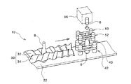
図1は、容器搬送システム10の搬送機構の概要を説明する図である。図2は、容器搬送システム10の全体構成図である。容器搬送システム10は、搬送機構部20と、搬送機構部20を構成する各要素の作動を全体として制御する制御装置70を含んで構成される。ここでは、容器搬送システム10の構成要素ではないが、搬送対象物である容器8としてプラスチックボトルが示され、また、この容器8に被せるものとして、筒状の熱収縮性フィルム6が示されている。なお、図1では、概要を説明するため、いくつかの構成要素の図示を省略し、搬送中の容器8についても、代表的な位置にある2つの容器8のみが図示されている。
FIG. 1 is a diagram for explaining the outline of the transport mechanism of the
容器搬送システム10は、矢印で示す搬送方向に複数の容器8を順次搬送し、熱収縮性フィルム6を被せる位置で一旦搬送を停留させ、その停留位置で熱収縮性フィルム6を容器8に被せた後、容器8の搬送を再び開始する機能を有する。
The
搬送機構部20は、搬送用ベルトコンベヤ22と、容器搬送路の両側に搬送方向に沿って平行に配置される一対のタイミングスクリュー30と、一対のタイミングスクリューの下流側において、容器搬送路の両側に搬送方向に沿って平行に配置される2組の回転ベルト40,42,50,52と、容器の位置を検出する位置検出センサ24と、容器8にラベルとしての筒状の熱収縮性フィルム6を装着するための装着装置36とを含んで構成される。
The
搬送用ベルトコンベヤ22は、矢印の方向に移動する連続体であり、その上に容器8を起立させた状態で搬送する機能を有する。搬送用ベルトコンベヤ22は、図示されていないモータ等で移動駆動される。
The
一対のタイミングスクリュー30は、容器搬送路を挟む2つのタイミングスクリュー軸32,34で構成され、容器搬送路に沿って容器を予め定めた搬送ピッチで案内して送る容器案内機構である。タイミングスクリュー軸32,34は、それぞれの旋回の向きを相互に反対とし、相互に反対向きに駆動回転されることで、向かい合った螺旋溝の間に容器8を挟んで搬送することができる。タイミングスクリュー軸32,34は、一定のピッチの螺旋溝を有し、軸方向に等速回転することで、螺旋溝が軸方向に等速で進行する。したがって、一対のタイミングスクリュー30を用いて容器8を搬送することで、搬送用ベルトコンベヤ22による搬送に比べ、時間的にも距離的にも正確な等間隔で容器8を搬送することができる。これにより、搬送速度を高速にしても、内容物の注入、ラベルの添付、計数その他の処理を正確に実行することが可能となる。
The pair of
2組の回転ベルト40,42,50,52は、容器8を搬送中に一時停止、すなわち搬送用ベルトコンベヤ22、一対のタイミングスクリュー30の動作を止めることなく、停留位置で容器8を一時停止させる機能を有するものである。容器8を停留位置で一時停止させることで、容器8が移動していると困難な処理を行うことができる。図1の例では、ラベルの装着装置36を用いて、ラベルである筒状の熱収縮性フィルム6を容器8に被せる場合が示されている。容器8が移動していると、うまく筒状のラベルが容器8に被せられないので、容器8の停留位置が熱収縮性フィルム6の供給位置の真下に設定されている。
The two sets of
そのために、2組の回転ベルト40,42,50,52が、一対のタイミングスクリュー30の下流側に設けられる。そして、一対のタイミングスクリュー30によって高速に等ピッチで搬送されてきた容器8を、2組の回転ベルト40,42,50,52の回転によって形成される搬送方向の移動隙間に受け取る。受け取りは、容器8の下部の胴部と上部の首部のそれぞれの外周側面を向かい合うベルトで挟み込むことで行われる。首部においてベルトによって挟みこまれる位置は、筒状ラベルが装着される容器の上部領域のすぐ下、すなわち容器の上方ラベル装着部の下端部であることが好ましい。そして、容器8を搬送方向に移動させ、所定の停留位置に来たときに2組の回転ベルト40,42,50,52の回転を停止し、そこで容器8の胴部と首部の外周側面を保持した状態で、容器8の移動が停止され、容器搬送が停留することになる。この停留位置で、ラベルの装着装置36から筒状の熱収縮性フィルム6が供給され、ラベルとして容器8の上方から被せられる。
For this purpose, two sets of
このような機能を有する2組の回転ベルト40,42,50,52は、容器8の胴部を保持するための1組の回転ベルト40,42と、容器8の首部を保持するための1組の回転ベルト50,52とで構成される。各回転ベルト40,42,50,52のそれぞれは、搬送方向に沿って間隔を置いて配置された2つの軸の間を循環して移動可能で、向かい合うベルトで容器8の外周を面接触で保持することができる。
The two sets of
図2では、容器の胴部を保持するための一方側の1組の回転ベルト40,42のうち、回転ベルト40について、環状のベルト44と、環状のベルト44の両側に設けられる2つの軸46,48が示されている。ここで、2つの軸46,48は、搬送方向に垂直な軸方向を有し、環状のベルト44のベルト面は、搬送用ベルトコンベヤ22の搬送面に対し垂直である。この2つの軸46,48はベルト44の駆動軸であり、少なくとも一方が図示されていないモータによって駆動され、制御装置70の制御の下で、正確なタイミングで回転、停止を行うことができる。もう1つの回転ベルト42も同様に、環状ベルトと2つの軸を含んで構成される。なお、各回転ベルト40,42,50,52には、それぞれの環状ベルトの張力を調整するための手段として、例えば、適当なテンション軸を設けることができる。
In FIG. 2, among the pair of
同様に、図2では、容器の首部を保持するための他方側の1組の回転ベルト50,52のうち、回転ベルト52について、環状のベルト55と、環状のベルト55の両側に設けられる2つの軸57,59が示されている。ここで、2つの軸57,59は、搬送方向に垂直な軸方向を有し、環状のベルト55のベルト面は、搬送用ベルトコンベヤ22の搬送面に対し垂直であることは、上記の回転ベルト40の場合と同様である。また、この2つの軸57,59はベルト55の駆動軸であり、少なくとも一方が図示されていないモータによって駆動され、制御装置70の制御の下で正確なタイミングで回転、停止を行うことができることも、回転ベルト40の場合と同様である。もう1つの回転ベルト50も同様に、環状ベルトと2つの軸を含んで構成される。
Similarly, in FIG. 2, among the pair of
これらの各回転ベルト40,42,50,52は、図示されていない適当な支持部によって、搬送用ベルトコンベヤ22の搬送移動を妨げないように搬送面から分離されて容器搬送路に対し所定の配置関係で配置される。なお、後述するように、回転ベルト40,42の間の幅間隔、回転ベルト50,52の間の幅間隔は、容器8の形状に合わせて調整が可能である。また、各回転ベルト40,42,50,52は、上記のように、図示されていない駆動装置であるモータによって、制御装置70の制御の下で同期して回転駆動される。
Each of the
これにより、回転ベルト40,42の向かい合うベルトの間隔を容器8の胴部の外形に合わせ、回転ベルト50,52の向かい合うベルトの間隔を容器8の首部の外形に合わせて、容器8の外周の側面にベルトを面接触させ、4つのベルトを同期移動させることで、容器8を4箇所の面接触で挟んだ状態で搬送を行うことができる。また、4つのベルトを同期して停止させることで、搬送用ベルトコンベヤ22が移動していてもその移動と切り離して、ベルトで挟まれた容器8を停止させることができる。
As a result, the distance between the belts facing the
図2には、6個の容器8が矢印の方向に順次搬送されている様子が示されている。6個の容器8は、図2の左側から右側に向かう搬送方向に沿って、搬送用ベルトコンベヤ22の上で起立して搬送されている状態の1個、タイミングスクリュー軸32,34に挟持されて搬送されている状態の2個、タイミングスクリュー軸32,34によって正確な搬送ピッチ状態にされた後、再び搬送用ベルトコンベヤ22によって起立搬送されている状態の1個、回転ベルト40,42,50,52によって停留位置に保持されている状態の1個、停留位置で筒状の熱収縮性フィルム6が被せられ、再び搬送用ベルトコンベヤ22によって起立搬送されている1個がそれぞれ示されている。
FIG. 2 shows a state in which six
位置検出センサ24は、タイミングスクリュー軸32,34の下流側において、容器8の位置を検出する機能を有する容器検出手段である。位置検出センサ24が容器8を検出する位置は、2組の回転ベルト40,42,50,52によって容器8が保持されて停止される位置である停留位置と関連付けて設定される。例えば、停留位置から上流側に所定の搬送距離を遡った位置において、容器8の有無が検出される。図2では、タイミングスクリュー軸32,34によって正確な搬送ピッチ状態にされた後、再び搬送用ベルトコンベヤ22によって起立搬送されている状態の容器8について、所定の位置に来たか否かが位置検出センサ24によって検出されている。かかる位置検出センサとしては、赤外センサ等の光学的センサ、超音波の反射を利用する超音波センサ等を用いることができる。
The
容器8が所定の検出位置に来たことを位置検出センサ24が検出すると、検出信号が制御装置70に伝送される。後述するように、制御装置70では、位置検出センサ24から検出位置に容器8が来たことを示す信号を受け取ったときは、回転ベルト40,42,50,52を駆動する駆動装置に作動指令を出す。この作動指令は、回転ベルト40,42,50,52を回転させて、搬送されて来た容器8を向かい合うベルトによって挟持させて搬送させ、ちょうど停留位置に来たときに、回転ベルト40,42,50,52を停止させ、ここで容器8を停留させるように制御が行われる。このタイミングは、容器8の検出位置と停留位置との配置関係に基いて設定される。
When the
装着装置36は、停止している回転ベルト40,42,50,52によって停留位置に保持されている容器8にラベルである筒状の熱収縮性フィルム6を供給する装置である。装着装置36は、回転ベルト40,42,50,52の上方に設けられ、筒状の熱収縮性フィルム6を下方に供給することで、停留位置にある容器8の首部の装着位置にこれを被せる。装着装置36が熱収縮性フィルム6を供給するタイミングは、制御装置70の制御の下で管理される。
The mounting
装着装置36によって容器8に熱収縮性フィルムが装着されたことは、図示されていない装着検出手段によって検出される。装着が完了したことを示す信号は制御装置70に伝送され、これによって回転ベルト40,42,50,52の停止指令が解除され、容器8は回転ベルト40,42,50,52に挟持されて、再び搬送が行われる。なお、装着検出手段を設けずに、回転ベルト40,42,50,52が停止してから予め定めた所定の時間経過をもって回転ベルト40,42,50,52の停止指令を解除するものとしてもよい。
That the heat shrinkable film is attached to the
制御装置70は、搬送機構部20を構成する各要素の動作を全体として制御し、容器8を定められた搬送速度で搬送させる機能を有する。ここでは特に、容器検出手段である位置検出センサ24が容器を検出したことに基いて、2組の回転ベルト40,42,50,52の移動を停止して2組の回転ベルト40,42,50,52で容器8を保持して停留させ、停留させた位置において容器8にラベルを装着させ、予め定めた所定の解除条件の下で2組の回転ベルト40,42,50,52の停止を解除して移動を再開させる機能を有する。
The
制御装置70は、一般的な搬送処理を行う搬送処理部80の他に、容器8が所定の検出位置に来たことを検出する容器検出部72、容器8が検出されたことに基いて容器8の搬送を一時停止させ、停留位置に停留させる停留処理部74、停留位置でラベルを容器8に装着させる装着処理部76、装着が完了した後に搬送の停止処理を解除して容器8を再び搬送する解除処理部78を含んで構成される。
In addition to the
かかる制御装置70は、コンピュータあるいは専用制御装置で構成することができる。また、上記各機能は、ソフトウェアで実現でき、具体的には、容器搬送制御プログラムを実行することで実現できる。上記機能の一部をハードウェアで実現するものとすることもできる。
The
上記構成の作用、特に制御装置70の各機能について、図3のフローチャートを用いて詳細に説明する。図3は、容器搬送の手順、特に容器搬送一時停留処理の手順を示すフローチャートで、その各手順は、容器搬送制御プログラムの各処理手順に対応する。
The operation of the above configuration, particularly each function of the
容器搬送を行うには、その容器に合わせた前準備が行われる。すなわち、搬送する容器8の寸法等に合わせて、一対のタイミングスクリュー30の選択とその交換配置設定が行われる(S10)。そして、回転ベルト40,42,50,52において向かい合うベルトの間の間隔が調整される(S12)。
In order to carry a container, preparations for the container are performed. In other words, the pair of timing screws 30 and the replacement arrangement are selected according to the dimensions of the
図4は、回転ベルト40,42,50,52の向かい合う間隔が、容器の形状によって変わることを説明する図である。左側の(a)には、小型の容器8が示されており、この場合には、胴部において向かい合うベルト44,45の間の間隔はW1であり、首部において向かい合うベルト54,55の間の間隔はB1であり、首部のベルト54,55の高さ位置はH1である。ここで高さ位置H1は、ラベル装着部の下端部の位置である。一方右側の(b)には大型の容器9が示されており、この場合の胴部において向かい合うベルト44,45の間の間隔はW2であり、首部において向かい合うベルト54,55の間の間隔はB2であり、首部のベルト54,55の高さ位置はH2である。
FIG. 4 is a diagram for explaining that the distance between the
したがって、回転ベルト40,42,50,52を用いて容器8,9の停留制御を行う場合には、容器8,9の形状、寸法が変更になったとき、各回転ベルト40,42,50,52の配置関係を変更するだけで済む。特に、W1=B1,W2=B2となるような場合には、単に回転ベルト40,42,50,52の幅間隔の調整のみで済む。各回転ベルト40,42,50,52の配置関係の変更は、勿論、手作業で行うことができるが、配置関係調整部としてのアクチュエータを用いて変更することもできる。例えば、切換スイッチあるいは切換ボタンを用いて、その操作のみで各回転ベルト40,42,50,52の配置関係を変更することができる。さらに、容器8,9の形状、寸法等を検出し、その結果に応じて自動的に各回転ベルト40,42,50,52の配置関係を変更するものとしてもよい。単に回転ベルト40,42,50,52の幅間隔の調整のみで済む場合には、配置関係調整部は、幅間隔を調整する幅調整部に相当することになる。
Therefore, when stopping control of the
再び図3に戻り、S10,S12において、例えば、容器8に対する一対のタイミングスクリュー30の交換、各回転ベルト40,42,50,52の配置関係の調整等の準備が完了すると、容器搬送システム10の始動とともに容器搬送制御プログラムが立ち上げる。そして、容器8が搬送路の上流側から搬入される(S20)。まず、搬送用ベルトコンベヤ22の上に容器8が起立した状態で搬送される(S22)。そして、一対のタイミングスクリュー30による搬送が行われ、各容器8の搬送ピッチが正確に揃えられる(S24)。その後一旦搬送用ベルトコンベヤ22の搬送が行われる(S26)。ここまでの工程は、制御装置70の搬送処理部78の機能によって実行される。
Returning to FIG. 3 again, in S10 and S12, for example, when preparations such as replacement of the pair of timing screws 30 with respect to the
そして、位置検出センサ24を用いて、容器8の搬送位置が予め定められた検出位置に来たか否かによって容器検出の有無が判断される(S28)。この判断は、制御装置70の容器検出部72の機能によって実行される。
Then, using the
容器8が検出されたと判断されると、回転ベルト40,42,50,52による搬送が行われる(S30)。そして、容器検出位置と停留位置との間の位置関係に基づく所定距離を移動した位置で、回転ベルト40,42,50,52は、その作動が停止される(S32)。これによって、搬送用ベルトコンベヤ22が移動していても、それにかかわらず、容器8は、向かい合うベルトに挟まれて保持され、正確に停留位置で一時停止の姿勢を取る。このように、停留位置において、熱収縮性フィルム6を被せるための位置決めが正確に行われるので、熱収縮性フィルム6を被せるための処理時間を効果的に短縮することができる。この工程は制御装置70の停留処理部74の機能によって実行される。
If it is determined that the
容器8が停留位置に停止すると、次にラベル装着が行われる(S34)。この工程は、制御装置70の装着処理部76の機能によって実行される。容器8が停留位置に停止することの確認は、上記のように容器検出からの所定距離移動によって行われるが、さらに、容器停止の検出を行う検出手段を設けるものとしてもよい。例えば、装着装置36において、停留位置に容器8が停止しているか否かを検出する手段を設けるものとしてもよい。ラベル装着は、装着装置36から筒状の熱収縮性フィルム6を下方の容器8の首部に向かって供給することで行うことができる。
When the
つぎに、装着完了か否かが判断される(S36)。この判断は、上記のように、装着検出手段を用い、容器8に熱収縮性フィルム6が被せられたか否かを検出することで行われる。また、装着検出手段を設けずに、回転ベルト40,42,50,52が停止してから予め定めた所定の時間経過をもって装着完了と判断するものとしてもよい。そして、装着完了と判断されると、回転ベルト40,42,50,52の停止指令が解除される(S38)。停止解除によって、回転ベルト40,42,50,52は再び作動を開始し、容器8は停留状態から解放され、回転ベルト40,42,50,52によって搬送される。この工程は、制御装置70の解除処理部78の機能によって実行される。そして、回転ベルト40,42,50,52の搬送範囲を過ぎると、容器8は再び搬送用ベルトコンベヤ22によって搬送され(S40)、次工程に搬出される(S42)。
Next, it is determined whether or not the mounting is completed (S36). As described above, this determination is made by detecting whether or not the heat-
このようにして、回転ベルト40,42,50,52を用いて、容器8の搬送を停留位置において、正確な位置決めの状態で、一時停止させ、その状態でラベルを装着することができる。
In this way, using the
上記では、容器8が回転ベルト40,42,50,52の向かい合うベルトの面接触によって保持され、搬送および停留位置における位置の固定が行われるものとして説明した。さらに保持を確実にするものとして、容器8の外周を保持するための保持爪部をベルトに設けることができる。
In the above description, it has been described that the
図5は、容器8の胴部を挟む一方側の回転ベルト41,43に保持爪部93,94,95,96を設けた例を示す図である。保持爪部は、各回転ベルト41,43にそれぞれ2つずつ設けられる。すなわち、回転ベルト41に2つの保持爪部93,94が設けられ、回転ベルト43に2つの保持爪部95,96が設けられる。回転ベルト41における2つの保持爪部93,94の間の間隔、および回転ベルト43における2つの保持爪部95,96の間の間隔は、容器8の胴部の外形をしっかりと保持できる寸法に設定される。回転ベルト41,43は制御装置70によって同期駆動されるので、最初に回転ベルト41,43における保持爪部93,94,95,96の相対的位置関係を正しく設定することで、保持爪部93,94,95,96によって、容器8を正確に起立姿勢に保持することができる。
FIG. 5 is a view showing an example in which holding
同様に、容器8の首部を保持するための他方側の回転ベルトにもそれぞれ保持爪部を設けることができる。図5と同様に他方側の回転ベルトのそれぞれに各2つずつの保持爪部を設けるものとすると、容器8は、胴部において4点で支持され、首部において4点で支持されることになる。この8つの保持爪部によって、容器8は、起立姿勢が再現性よく正しく確保され、熱収縮性フィルム6を被せる際の位置が正確に確保できる。
Similarly, a holding claw portion can be provided on each of the other rotating belts for holding the neck portion of the
上記において、容器搬送路に沿って容器8を予め定めた搬送ピッチで案内して送るために、容器搬送路の両側に搬送方向に沿って平行に配置される一対のタイミングスクリュー30を用いるものとして説明した。これ以外の容器案内機構として、図6に示す1つのタイミングスクリュー軸34とこれに向かい合う送りベルト90の組合せ機構を用いてもよい。あるいは、図7に示すスターホイール92とこれに向かい合う送りベルト90の組合せ機構を用いるものとすることができる。
In the above, in order to guide and send the
6 熱収縮性フィルム、8,9 容器、10 容器搬送システム、20 搬送機構部、22 搬送用ベルトコンベヤ、24 位置検出センサ、30 タイミングスクリュー、32,34 タイミングスクリュー軸、36 装着装置、40,41,42,43,50,52 回転ベルト、44,45,54,55 ベルト、46,48,57,59 軸、70 制御装置、72 容器検出部、74 停留処理部、76 装着処理部、78 解除処理部、80 搬送処理部、90 送りベルト、92 スターホイール、93,94,95,96 保持爪部。 6 heat-shrinkable film, 8, 9 container, 10 container transport system, 20 transport mechanism, 22 transport belt conveyor, 24 position detection sensor, 30 timing screw, 32, 34 timing screw shaft, 36 mounting device, 40, 41 , 42, 43, 50, 52 Rotating belt, 44, 45, 54, 55 Belt, 46, 48, 57, 59 Axis, 70 Control device, 72 Container detection unit, 74 Stopping processing unit, 76 Mounting processing unit, 78 Release Processing unit, 80 conveyance processing unit, 90 feeding belt, 92 star wheel, 93, 94, 95, 96 holding claw unit.
Claims (3)
容器案内機構の下流側において、容器搬送路の両側に搬送方向に沿って予め定められた所定の幅間隔で平行に向かい合って配置される2組の回転ベルトであって、一方の組の回転ベルトは容器の下方胴部の幅間隔で向かい合い、他方の組の回転ベルトは容器にラベルが装着される上方ラベル装着部の下端部の幅間隔で向かい合い、それぞれの組の回転ベルトは、搬送方向に沿って間隔を置いて配置された少なくとも2つの軸の間を循環して移動可能で、向かい合うベルト表面で容器を挟んで保持する2組の回転ベルトと、
容器案内機構の下流側において、予め定めた所定の検出位置に容器が搬送されたか否かを検出する容器検出手段と、
容器検出手段が容器を検出したことに基いて2組の回転ベルトの移動を停止して2組の回転ベルトで容器を保持して停留させ、停留させた位置において容器にラベルを装着させ、予め定めた所定の解除条件の下で2組の回転ベルトの停止を解除して移動を再開させる制御装置と、
を備えることを特徴とする容器搬送システム。 A container guide mechanism that guides and sends the container at a predetermined transport pitch along the container transport path;
Two sets of rotating belts disposed on both sides of the container conveying path on the downstream side of the container guiding mechanism so as to face each other in parallel with a predetermined width interval along the conveying direction. Face each other at the width interval of the lower body of the container, and the other set of rotating belts face each other at the width interval of the lower end of the upper label mounting portion on which the label is mounted on the container. Two sets of rotating belts that can circulate and move between at least two axes spaced apart alongside and hold the container between opposing belt surfaces;
Container detecting means for detecting whether or not the container has been transported to a predetermined detection position on the downstream side of the container guiding mechanism;
Based on the detection of the container by the container detection means, the movement of the two sets of rotating belts is stopped, the containers are held and stopped by the two sets of rotating belts, and a label is attached to the container at the stopped position. A control device for releasing the stop of the two sets of rotating belts and resuming the movement under predetermined predetermined release conditions;
A container transport system comprising:
少なくとも1組の回転ベルトは、容器の外周を保持する保持爪部を有することを特徴とする容器搬送システム。 In the container transport system according to claim 1,
At least one set of rotating belts has a holding claw for holding the outer periphery of the container.
各組の回転ベルトについて、平行に配置される所定の幅間隔を可変する幅調整部を備えることを特徴とする容器搬送システム。 In the container conveyance system according to claim 1,
A container transport system comprising: a width adjusting unit that varies a predetermined width interval arranged in parallel for each set of rotating belts.
Priority Applications (1)
| Application Number | Priority Date | Filing Date | Title |
|---|---|---|---|
| JP2008048218A JP5164606B2 (en) | 2008-02-28 | 2008-02-28 | Container transfer system |
Applications Claiming Priority (1)
| Application Number | Priority Date | Filing Date | Title |
|---|---|---|---|
| JP2008048218A JP5164606B2 (en) | 2008-02-28 | 2008-02-28 | Container transfer system |
Publications (2)
| Publication Number | Publication Date |
|---|---|
| JP2009203033A true JP2009203033A (en) | 2009-09-10 |
| JP5164606B2 JP5164606B2 (en) | 2013-03-21 |
Family
ID=41145678
Family Applications (1)
| Application Number | Title | Priority Date | Filing Date |
|---|---|---|---|
| JP2008048218A Expired - Fee Related JP5164606B2 (en) | 2008-02-28 | 2008-02-28 | Container transfer system |
Country Status (1)
| Country | Link |
|---|---|
| JP (1) | JP5164606B2 (en) |
Cited By (4)
| Publication number | Priority date | Publication date | Assignee | Title |
|---|---|---|---|---|
| CN103587933A (en) * | 2013-12-03 | 2014-02-19 | 莱州市同力机械有限公司 | Double helix bottle separating device |
| CN104029991A (en) * | 2014-05-21 | 2014-09-10 | 成都中牧生物药业有限公司 | Ampoule fixed-distance conveying device |
| CN106564750A (en) * | 2016-10-21 | 2017-04-19 | 张家港市万金机械有限公司 | Full-automatic bottle feeding screw sorting device |
| CN111617988A (en) * | 2020-05-06 | 2020-09-04 | 浙江虎哥环境有限公司 | Automatic sorting workstation of old and useless glass |
Families Citing this family (1)
| Publication number | Priority date | Publication date | Assignee | Title |
|---|---|---|---|---|
| CN103274199B (en) * | 2013-05-10 | 2015-11-18 | 广州达意隆包装机械股份有限公司 | Bottle separating device |
Citations (7)
| Publication number | Priority date | Publication date | Assignee | Title |
|---|---|---|---|---|
| JPH10203618A (en) * | 1997-01-24 | 1998-08-04 | Mitsubishi Materials Corp | Can conveyer |
| JP2979313B1 (en) * | 1998-07-30 | 1999-11-15 | 株式会社フジヤマ技研 | Stopping device in bottle transfer device |
| JP2000117640A (en) * | 1998-10-09 | 2000-04-25 | Fuji Seisakusho:Kk | Method and device for carrying article to be machined in blast machining |
| JP2000168945A (en) * | 1998-12-07 | 2000-06-20 | Kirin Techno System:Kk | Conveyer for preform inspection |
| JP2003252301A (en) * | 2002-02-27 | 2003-09-10 | Gunze Ltd | Cap seal fitting apparatus |
| JP2004026434A (en) * | 2002-06-26 | 2004-01-29 | Asahi Breweries Ltd | Container control device and manufacture related facility |
| JP2007269423A (en) * | 2006-03-30 | 2007-10-18 | Toyo Seikan Kaisha Ltd | Plastic bottle conveying device |
-
2008
- 2008-02-28 JP JP2008048218A patent/JP5164606B2/en not_active Expired - Fee Related
Patent Citations (7)
| Publication number | Priority date | Publication date | Assignee | Title |
|---|---|---|---|---|
| JPH10203618A (en) * | 1997-01-24 | 1998-08-04 | Mitsubishi Materials Corp | Can conveyer |
| JP2979313B1 (en) * | 1998-07-30 | 1999-11-15 | 株式会社フジヤマ技研 | Stopping device in bottle transfer device |
| JP2000117640A (en) * | 1998-10-09 | 2000-04-25 | Fuji Seisakusho:Kk | Method and device for carrying article to be machined in blast machining |
| JP2000168945A (en) * | 1998-12-07 | 2000-06-20 | Kirin Techno System:Kk | Conveyer for preform inspection |
| JP2003252301A (en) * | 2002-02-27 | 2003-09-10 | Gunze Ltd | Cap seal fitting apparatus |
| JP2004026434A (en) * | 2002-06-26 | 2004-01-29 | Asahi Breweries Ltd | Container control device and manufacture related facility |
| JP2007269423A (en) * | 2006-03-30 | 2007-10-18 | Toyo Seikan Kaisha Ltd | Plastic bottle conveying device |
Cited By (6)
| Publication number | Priority date | Publication date | Assignee | Title |
|---|---|---|---|---|
| CN103587933A (en) * | 2013-12-03 | 2014-02-19 | 莱州市同力机械有限公司 | Double helix bottle separating device |
| CN103587933B (en) * | 2013-12-03 | 2015-07-22 | 莱州市同力机械有限公司 | Double helix bottle separating device |
| CN104029991A (en) * | 2014-05-21 | 2014-09-10 | 成都中牧生物药业有限公司 | Ampoule fixed-distance conveying device |
| CN104029991B (en) * | 2014-05-21 | 2016-02-17 | 成都中牧生物药业有限公司 | Ampulla spacing conveyer |
| CN106564750A (en) * | 2016-10-21 | 2017-04-19 | 张家港市万金机械有限公司 | Full-automatic bottle feeding screw sorting device |
| CN111617988A (en) * | 2020-05-06 | 2020-09-04 | 浙江虎哥环境有限公司 | Automatic sorting workstation of old and useless glass |
Also Published As
| Publication number | Publication date |
|---|---|
| JP5164606B2 (en) | 2013-03-21 |
Similar Documents
| Publication | Publication Date | Title |
|---|---|---|
| JP5164606B2 (en) | Container transfer system | |
| WO2012137416A1 (en) | Loading device for tire testing machine | |
| JP6027105B2 (en) | Cylindrical film body fitting apparatus and method | |
| US10029862B2 (en) | Conveying system | |
| KR101724841B1 (en) | Protection film attaching apparatus | |
| JP2006213475A (en) | Container carrying device | |
| JP3955335B2 (en) | Container inspection machine | |
| US8733416B2 (en) | Label applicator | |
| JPH04367432A (en) | Direction regulating device for container | |
| CN110304474B (en) | Medium conveying device, recording device, and method for determining skew state of conveyor belt | |
| CN106794703A (en) | Digital printer | |
| JP5138626B2 (en) | Film feeder | |
| JPH11105839A (en) | Apparatus and method for sticking label | |
| JP2008161977A (en) | Assembly line system | |
| JP4729192B2 (en) | Film feeder | |
| JPH1111447A (en) | Label peeler | |
| JP4828187B2 (en) | Label supply system and label mounting system | |
| JPH07132905A (en) | Method of shutting case cover in transfer line and apparatus thereof | |
| WO2022009736A1 (en) | Transported article discharge device | |
| JP7429165B2 (en) | Transport device for transported objects | |
| JP5917101B2 (en) | Film fitting device | |
| JP4768594B2 (en) | Assembly line system | |
| JP2007022732A (en) | Article delivering device | |
| JPH03256833A (en) | Labeling device | |
| JP2021031140A (en) | Head mechanism of label pasting device, label pasting device and label pasting method |
Legal Events
| Date | Code | Title | Description |
|---|---|---|---|
| A621 | Written request for application examination |
Free format text: JAPANESE INTERMEDIATE CODE: A621 Effective date: 20110105 |
|
| A977 | Report on retrieval |
Free format text: JAPANESE INTERMEDIATE CODE: A971007 Effective date: 20120501 |
|
| A131 | Notification of reasons for refusal |
Free format text: JAPANESE INTERMEDIATE CODE: A131 Effective date: 20121002 |
|
| A521 | Request for written amendment filed |
Free format text: JAPANESE INTERMEDIATE CODE: A523 Effective date: 20121127 |
|
| TRDD | Decision of grant or rejection written | ||
| A01 | Written decision to grant a patent or to grant a registration (utility model) |
Free format text: JAPANESE INTERMEDIATE CODE: A01 Effective date: 20121211 |
|
| A61 | First payment of annual fees (during grant procedure) |
Free format text: JAPANESE INTERMEDIATE CODE: A61 Effective date: 20121218 |
|
| FPAY | Renewal fee payment (event date is renewal date of database) |
Free format text: PAYMENT UNTIL: 20151228 Year of fee payment: 3 |
|
| R150 | Certificate of patent or registration of utility model |
Ref document number: 5164606 Country of ref document: JP Free format text: JAPANESE INTERMEDIATE CODE: R150 Free format text: JAPANESE INTERMEDIATE CODE: R150 |
|
| FPAY | Renewal fee payment (event date is renewal date of database) |
Free format text: PAYMENT UNTIL: 20151228 Year of fee payment: 3 |
|
| R250 | Receipt of annual fees |
Free format text: JAPANESE INTERMEDIATE CODE: R250 |
|
| R250 | Receipt of annual fees |
Free format text: JAPANESE INTERMEDIATE CODE: R250 |
|
| R250 | Receipt of annual fees |
Free format text: JAPANESE INTERMEDIATE CODE: R250 |
|
| R250 | Receipt of annual fees |
Free format text: JAPANESE INTERMEDIATE CODE: R250 |
|
| R250 | Receipt of annual fees |
Free format text: JAPANESE INTERMEDIATE CODE: R250 |
|
| R250 | Receipt of annual fees |
Free format text: JAPANESE INTERMEDIATE CODE: R250 |
|
| R250 | Receipt of annual fees |
Free format text: JAPANESE INTERMEDIATE CODE: R250 |
|
| LAPS | Cancellation because of no payment of annual fees |