JP2009201880A - Standing-up training instrument, and standing-up/back muscle training instrument - Google Patents
Standing-up training instrument, and standing-up/back muscle training instrument Download PDFInfo
- Publication number
- JP2009201880A JP2009201880A JP2008049338A JP2008049338A JP2009201880A JP 2009201880 A JP2009201880 A JP 2009201880A JP 2008049338 A JP2008049338 A JP 2008049338A JP 2008049338 A JP2008049338 A JP 2008049338A JP 2009201880 A JP2009201880 A JP 2009201880A
- Authority
- JP
- Japan
- Prior art keywords
- swing arm
- load
- pair
- main body
- swing
- Prior art date
- Legal status (The legal status is an assumption and is not a legal conclusion. Google has not performed a legal analysis and makes no representation as to the accuracy of the status listed.)
- Withdrawn
Links
Images


Landscapes
- Rehabilitation Tools (AREA)
Abstract
Description
本発明は、高齢者などの立上り訓練に用いる立上り訓練具、また立上り及び背筋の訓練に用いる立上り・背筋訓練具に関する。 The present invention relates to a standing-up training tool used for standing-up training for an elderly person and the like, and a standing-up / back muscle training tool used for standing-up and back muscle training.
高齢者の中には、足腰が弱り、立上りが難しくなるケースが見られる。この立上りが難しくなると、自分で立って歩行することが難しくなり、歩行するためには介護者などが必要となり、だんだん歩行することが少なくなって足腰がいっそう弱くなり、足腰が弱って歩行困難となる悪循環に陥る。 Some elderly people have weak legs, making it difficult to get up. When this rise becomes difficult, it becomes difficult to stand and walk on its own, and a caregiver is required to walk, and gradually walking becomes less and the legs and hips become weaker, and the legs and legs become weak and difficult to walk. Falls into a vicious circle.
一方、トレーニング器具(トレーニングマシン)としては、腕などを鍛えるものが種々提案されている(例えば、特許文献1参照)。このトレーニング器具は、床面に設置される基台と、基台に設けられた移動部材と、移動部材に負荷を付与するための負荷付与手段と、負荷付与手段の負荷を移動部材に伝達するための負荷伝達手段とを備え、訓練者は負荷付与手段の負荷に抗して移動部材を移動させ、このように移動部材を移動させて腕など筋力アップを図っている。 On the other hand, various training instruments (training machines) for training arms and the like have been proposed (see, for example, Patent Document 1). The training device includes a base installed on the floor, a moving member provided on the base, a load applying unit for applying a load to the moving member, and a load applied to the load applying unit to the moving member. The trainee moves the moving member against the load of the load applying means, and moves the moving member in this way to increase the strength of the arm and the like.
しかしながら、上述したトレーニング器具は、腕などの筋力アップを図るためのもので、高齢者などの立上り訓練に用いることができず、近年の高齢化により問題になっている高齢者の立上り訓練を行うことができる訓練具の実現が強く望まれている。 However, the above-described training device is intended to increase the strength of the arm and the like, and cannot be used for the rising training of the elderly and the like, and performs the rising training of the elderly that has become a problem due to the recent aging Realization of a training tool that can be used is strongly desired.
本発明の目的は、高齢者などの立上りの訓練に用いることができる立上り訓練具を提供することである。
また、本発明の他の目的は、高齢者などの立上りの訓練に用いることができるとともに、背筋の訓練にも用いることができる立上り・背筋訓練具を提供することである。
An object of the present invention is to provide a start-up training tool that can be used for start-up training of an elderly person or the like.
Another object of the present invention is to provide a rising / back muscle training tool that can be used for training for standing up of an elderly person and the like, and can also be used for training of the back muscles.
本発明の請求項1に記載の立上り訓練具は、床面に設置される装置本体と、前記装置本体に所定方向に延びる揺動軸線を中心として揺動自在に装着された揺動アームと、前記揺動アームに取り付けられたクッションと、前記揺動アームに負荷を付与するための負荷付与手段と、前記負荷付与手段からの負荷を前記揺動アームに伝達するための負荷伝達手段と、前記装置本体に取り付けられた一対の把持手段と、前記一対の把持手段に対向して前記装置本体に取り付けられた座部材とを具備し、
前記一対の把持手段を把持し且つ前記座部材に座った状態にて前記揺動アームの前記クッションを両太股の上側に作用させ、かかる状態にて前記座部材から立ち上がるようにして前記揺動アームを前記揺動軸線を中心として揺動させて立上り運動を行うことを特徴とする。
A rising training tool according to claim 1 of the present invention includes a device main body installed on a floor surface, a swing arm mounted on the device main body so as to be swingable about a swing axis extending in a predetermined direction, A cushion attached to the swing arm; load applying means for applying a load to the swing arm; load transmitting means for transmitting a load from the load applying means to the swing arm; A pair of gripping means attached to the apparatus main body, and a seat member attached to the apparatus main body facing the pair of gripping means,
The swing arm is configured to act on the upper side of both thighs while holding the pair of gripping means and sitting on the seat member, and to stand up from the seat member in such a state. Is caused to swing around the swing axis to perform a rising motion.
また、本発明の請求項2に記載の立上り訓練具では、前記装置本体は横方向に間隔をおいて配設された一対の支持フレームを備え、前記揺動アームは前記一対の支持アーム間に支持軸を介して揺動自在に装着され、前記揺動アームの両側に前記クッションが装着され、両太股の間に前記揺動アームを位置付け、前記揺動アームの片方の前記クッションを片方の脚の太股の上側に作用させるとともに、前記揺動アームの他方の前記クッションを他方の脚の太股の上側に作用させ、かかる状態にて前記座部材から立ち上がるようにして前記揺動アームを前記支持軸を中心として揺動させて立上り運動を行うことを特徴とする。
Further, in the rising training tool according to
また、本発明の請求項3に記載の立上り訓練具は、床面に設置される装置本体と、前記装置本体に所定方向に延びる揺動軸線を中心として揺動自在に装着された揺動アームと、前記揺動アームに設けられた一対の把持手段と、前記揺動アームに負荷を付与するための負荷付与手段と、前記負荷付与手段からの負荷を前記揺動アームに伝達するための負荷伝達手段と、前記負荷伝達手段に関連して設けられた案内手段と、前記装置本体に取り付けられた座部材とを具備し、
前記負荷伝達手段は前記案内手段を通して前記揺動アームに連結され、前記座部材に座って前記一対の把持手段を把持し、かかる状態にて前記揺動アームを手前側に引っ張って前記揺動アームを所定方向に揺動させて前記案内手段の上部に案内させるようにして背筋運動を行い、また前記揺動アームを背面側に押して前記揺動アームを所定方向と反対方向に揺動させて前記案内手段の下部に案内させるようにして立上り運動を行うことを特徴とする。
According to a third aspect of the present invention, there is provided a stand-up training device comprising: a device main body installed on a floor surface; and a swing arm that is swingably mounted on the device main body about a swing axis extending in a predetermined direction. A pair of gripping means provided on the swing arm, a load applying means for applying a load to the swing arm, and a load for transmitting the load from the load applying means to the swing arm Transmission means, guide means provided in association with the load transmission means, and a seat member attached to the apparatus main body,
The load transmitting means is connected to the swing arm through the guide means, sits on the seat member and grips the pair of grip means, and in this state, pulls the swing arm toward the front side to swing the swing arm. Is swung in a predetermined direction so as to be guided to the upper part of the guide means, and the swing arm is pushed to the back side to swing the swing arm in a direction opposite to the predetermined direction. A rising motion is performed by guiding the lower part of the guide means.
更に、本発明の請求項4に記載の立上り・背筋訓練具では、前記案内手段は、上下方向に隣接して配設された上案内プーリ及び下案内プーリから構成され、前記揺動アームは略L字状に形成され、前記負荷伝達手段は前記家案内プーリと前記下案内プーリとの間を通して前記揺動アームの一端部に連結され、前記揺動アームの他端部に前記一対の把持手段が設けられており、前記座部材に座って前記一対の把持手段を把持し、かかる状態にて前記揺動アームを手前側に引っ張って前記揺動アームを所定方向に揺動させて前記負荷伝達手段を前記上案内プーリに案内させるようにして背筋運動を行い、また前記揺動アームを背面側に押して前記揺動アームを所定方向と反対方向に揺動させて前記下案内プーリに案内させるようにして立上り運動を行うことを特徴とする。 Furthermore, in the rising / back muscle training tool according to claim 4 of the present invention, the guide means is composed of an upper guide pulley and a lower guide pulley arranged adjacent to each other in the vertical direction, and the swing arm is substantially the same. The load transmitting means is connected to one end of the swing arm through the house guide pulley and the lower guide pulley, and the pair of gripping means is connected to the other end of the swing arm. Sitting on the seat member, gripping the pair of gripping means, and pulling the swing arm toward this side in this state to swing the swing arm in a predetermined direction to transmit the load. The spine exercise is performed by guiding the means to the upper guide pulley, and the swing arm is pushed to the back side to swing the swing arm in a direction opposite to a predetermined direction and guided to the lower guide pulley. Stand up exercise And performing.
本発明の請求項1に記載の立上り訓練具によれば、装置本体に揺動軸線を中心として揺動自在に装着された揺動アームが装着され、この揺動アームにクッションが取り付けられているとともに、装置本体に一対の把持手段が取り付けられ、揺動アームと負荷付与手段とが負荷伝達手段を介して連結されている。そして、訓練するときには、一対の把持手段を把持し且つ座部材に座った状態にて揺動アームのクッションを両太股の上側に作用させるで、座部材に座った状態から立上り動作を行うと、この動作の際に負荷付与手段からの負荷が負荷伝達手段、揺動アーム及びクッションを介して訓練者の両太股に作用し、この立上り、座りの動作を繰り返して立上り運動を行うことによって、立上りに寄与する臀筋群を働かせ、この臀筋群の筋力アップを図ることができる。 According to the rising training tool of the first aspect of the present invention, the swinging arm that is swingably mounted about the swinging axis is mounted on the apparatus main body, and the cushion is mounted on the swinging arm. In addition, a pair of gripping means is attached to the apparatus main body, and the swing arm and the load applying means are coupled via the load transmitting means. And when training, by holding the pair of gripping means and sitting on the seat member, the cushion of the oscillating arm is applied to the upper side of both thighs, so that when standing up from the state sitting on the seat member, During this operation, the load from the load applying means acts on both the thighs of the trainee through the load transmitting means, the swing arm and the cushion, and the rising motion is performed by repeating the rising and sitting motions to perform the rising motion. By working the gluteal muscle group that contributes to this, the muscular strength of this gluteal muscle group can be increased.
また、本発明の請求項2に記載の立上り訓練具によれば、揺動アームが一対の支持アーム間に支持軸を介して揺動自在に装着され、前記揺動アームの両側にクッションが装着されている。そして、訓練をするときには、揺動アームを両太股の間に位置付け、片方のクッションを片方の脚の太股の上側に作用させるとともに、他方のクッションを他方の脚の太股の上側に作用させるので、かかる状態にて座部材からの自然な立上り動作を行うことができ、立上り、座りの動作を繰り返して臀筋群の筋力アップを図ることができる。 According to the rising training tool of the second aspect of the present invention, the swing arm is swingably mounted between the pair of support arms via the support shaft, and cushions are mounted on both sides of the swing arm. Has been. And when training, the swing arm is positioned between both thighs, and one cushion acts on the upper leg of one leg and the other cushion acts on the upper leg of the other leg, In this state, it is possible to perform a natural rising operation from the seat member, and it is possible to increase the strength of the gluteal muscle group by repeating the rising and sitting operations.
また、本発明の請求項3に記載の立上り訓練具によれば、装置本体に揺動軸線を中心として揺動自在に揺動アームが装着され、この揺動アームに一対の把持手段が設けられ、この揺動アームと負荷付与手段とが負荷伝達手段を介して連結され、この負荷伝達手段に関連して案内手段が設けられている。そして、訓練をするときには、座部材に座って一対の把持手段を把持し、かかる状態にて揺動アームを手前側に引っ張ると、揺動アームが所定方向に揺動されて負荷伝達手段が案内手段の上部に案内され、このような引っ張り動作を繰り返して背筋運動を行うことにより、背筋運動に寄与する広背筋を働かせ、この広背筋の筋力アップを図ることができる。また、上述した状態にて揺動アームを背面側に押すと、揺動アームが所定方向と反対方向に揺動されて負荷伝達手段が案内手段の下部に案内され、このような押し動作を繰り返すことにより、立上りに寄与する腸腰筋を働かせ、この腸腰筋の筋力アップを図ることができる。 According to the rising training tool of the third aspect of the present invention, the swinging arm is swingably mounted on the apparatus main body about the swinging axis, and the swinging arm is provided with a pair of gripping means. The swing arm and the load applying means are connected via a load transmission means, and a guide means is provided in association with the load transmission means. When training, the user sits on the seat member and grips the pair of gripping means. When the swinging arm is pulled to the near side in this state, the swinging arm swings in a predetermined direction and the load transmitting means guides. By guiding the upper part of the means and repeating such a pulling motion to perform the back muscle movement, the latissimus dorsi muscle that contributes to the back muscle movement can be used, and the muscle strength of the wide back muscle can be increased. Further, when the swing arm is pushed to the back side in the above-described state, the swing arm is swung in the direction opposite to the predetermined direction, and the load transmitting means is guided to the lower portion of the guide means, and such pushing operation is repeated. As a result, the iliopsoas muscle that contributes to the rise can be worked and the muscular strength of the iliopsoas muscle can be increased.
更に、本発明の請求項4に記載の立上り・背筋訓練具によれば、案内手段が案内プーリ及び下案内プーリから構成され、負荷伝達手段は上案内プーリと下案内プーリとの間を通して揺動アームの一端部に連結され、この揺動アームの他端部に一対の把持手段が設けられているので、座部材に座って一対の把持手段を把持し、かかる状態にて揺動アームを手前側に引っ張って揺動アームを所定方向に揺動させることにより、負荷伝達手段が上案内プーリに案内されるようになり、これにより自然な引っ張り動作を行い、この揺動アームの引っ張り動作を繰り返して広背筋の筋力アップを図ることができ、また揺動アームを背面側に押して揺動アームを所定方向と反対方向に揺動させることにより、負荷伝達手段が下案内プーリに案内されるようになり、これにより自然な押し動作を行い、この揺動アームの押し動作を繰り返して腸腰筋の筋力アップを図ることができる。 Furthermore, according to the rising / back muscle training tool of claim 4 of the present invention, the guide means comprises the guide pulley and the lower guide pulley, and the load transmission means swings between the upper guide pulley and the lower guide pulley. Since it is connected to one end of the arm and a pair of gripping means is provided at the other end of the swing arm, the pair of gripping means is seated on the seat member and the swing arm is moved forward in this state. By pulling to the side, the swing arm is swung in a predetermined direction, so that the load transmission means is guided by the upper guide pulley, thereby performing a natural pulling operation and repeating the pulling operation of the swing arm. The strength of the latissimus dorsi muscles can be increased, and the load transmitting means can be guided by the lower guide pulley by pushing the swing arm to the back side and swinging the swing arm in the direction opposite to the predetermined direction. Now, As a result, the system indicates the natural push operation, it is possible to improve the muscle-up of the psoas muscle by repeating the press operation of the swing arm.
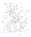
以下、添付図面を参照して、更に説明する。まず、図1〜図4を参照して、本発明に従う立上り練器具の一実施形態について説明する。図1は、立上り訓練具の一実施形態を示す側面図であり、図2は、図1の立上り訓練具の正面図であり、図3は、図1の立上り訓練具の背面を示す背面図であり、図4は、図1の立上り訓練具を用いた立上り訓練時における立上り姿勢を説明するための図である。 Hereinafter, further description will be given with reference to the accompanying drawings. First, with reference to FIGS. 1-4, one Embodiment of the rising training apparatus according to this invention is described. 1 is a side view showing an embodiment of the rising training tool, FIG. 2 is a front view of the rising training tool of FIG. 1, and FIG. 3 is a rear view showing the back of the rising training tool of FIG. FIG. 4 is a diagram for explaining a rising posture at the time of rising training using the rising training tool of FIG.
図1及び図2において、図示の立上り訓練具2は、床面4に設置される装置本体6を備え、この装置本体6の前部側(図1において右側、図2において紙面に対して手前側)が訓練部8となり、その後部側(図1において左側、図2において紙面に対して裏側)が負荷部10となっている。訓練部8はフレーム構造となり、負荷部10は後面が開放されたハウジング構造となっている。
1 and 2, the illustrated
この実施形態では、装置本体6は基台フレーム12を備え、この基台フレーム12の後端部に、断面形状コ字状の垂直フレーム本体14が設けられ、この垂直フレーム本体14の前面側が立上り訓練部8となり、その後面側が負荷部10となっている。この基台フレーム12の前端部には座部材16が設けられている(図2において、座部材16を省略して示している)。座部材16は、基台フレーム12から上方に延びる脚部18と、この脚部18の上端部に設けられた座部20とを備え、訓練者(トレーニング者)22は、後述するように、この座部20に座った状態から立ち上がる立上り運動を行う。
In this embodiment, the apparatus body 6 includes a
この実施形態では、基台フレーム12の前後方向(図1において左右方向、図2において紙面に垂直な方向)の中間部(負荷部10と座部材16との間の部位)に、幅方向(図1において紙面に垂直な方向、図2において左右方向)に間隔をおいて一対の支持フレーム24,26が設けられ、これら支持フレーム24,26は、基台フレーム12から実質上垂直上方に延びている。一対の支持フレーム24,26の上端部には支持軸28が回転自在に支持され、この支持軸28を介して揺動アーム30が揺動自在に支持され、この支持軸28が揺動軸線を構成する。
In this embodiment, the width direction (the portion between the
揺動アーム30は直線状に延びるアーム本体32を備え、このアーム本体32の軸方向略中央部に支持軸28が設けられ、この支持軸28が一対の支持フレーム24,26に回転自在に支持されている。この揺動アーム30の一端部には、両側に突出する軸部34が設けられ、かかる軸部34を覆うようにローラ状のクッション36が取り付けられている。また、アーム本体32の他端部とその中間部に設けられた支持棒40との間に、弧状の案内部38が設けられている。
The
また、この装置本体2の前面には、立上り運動時に訓練者が把持するための一対の把持手段42,44が座部材16に対向して設けられている。一対の把持手段42,44は実質上同一の構成であり、以下それらの一方の把持手段42(44)について説明する。把持手段42(44)は、支持部材46と、この支持部材の先端部に設けられた把持部45と、この支持部材46をロック保持するためのロック手段47(第1ロック手段を構成する)とを備えている。垂直フレーム本体14の上部両側部には一対の案内支持部材48,50が設けられ、これら案内支持部材48,50は訓練部8に向けて前方に延び、かかる案内支持部材48,50に把持手段42,44の支持部材46が前後方向に移動自在に装着されている。
In addition, a pair of gripping
この実施形態では、把持手段42,44の支持部材46及び案内支持部材48.50は例えば断面矩形状のパイプ状部材から構成され、これら支持部材46の外形が案内支持部材48.50の外形よりも幾分小さく、これら支持部材46の後端側が案内支持部材48.50内に移動自在に収容されている。また、案内支持部材48,50にはロック孔(図示せず)が設けられ、把持手段42,44の支持部材46には長手方向に間隔をおいて複数の位置調整用孔(図示せず)が設けられている。また、ロック手段47はロックピン52から構成され、このロックピン52がロック孔及び複数の位置調整孔のいずれかを通して挿入される。例えば、支持部材46を案内支持部材48(50)に収容して(又は引き出して)その先端側(又は基部側)の位置調整孔にロックピン52を挿入することによって、把持部45が訓練部8から離れる(又は近づく)ように調整することができ、この把持部45は、例えば、図1に実線で示す位置と図1に一点鎖線で示す位置との間を位置調整自在に構成される。
In this embodiment, the
把持手段42,44の上述した位置調整機構は、旋回アーム30のアーム本体32及び座部材16の脚部18にも適用されており、アーム本体32においては、この位置調整機構により、アーム本体32の一端側の長さを調整してクッション36の作用する位置を変えることができ、また座部材16の脚部18においては、この位置調整機構により、脚部18の長さを調整して座部20の高さを変えることができる。
The above-described position adjusting mechanism of the gripping
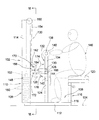
次に、負荷部10及びそれに関連する構成について説明する。図3をも参照して、垂直フレーム本体14は断面形状はコ字状であり、その内部に揺動アーム30に負荷を付与するための負荷付与手段54が配設されている。負荷付与手段54は、複数のウエイト56と、これらウエイト56を支持するための支持ロッド58と、これらウエイト56を支持ロッド58に解除自在にロックするための連結ピン60から構成されている。各ウエイト56は重量が例えば5kg程度のブロック状に形成され、その中央部には上下方向に貫通して貫通孔が設けられ、これら貫通孔内に支持ロッド58が挿入される。また、各ウエイト56の底部には、水平方向に延びる連結凹部が設けられているとともに、支持ロッド58には、上下方向に積層されたウエイト56の連結凹部に対応して連結孔(図示せず)が設けられ、ウエイト56を支持ロッド58に連結するために連結ピン60が特定のウエイト56の連結凹部及び支持ロッド58の対応する連結孔を通して挿通され、このように挿通することによって、この連結ピン60を介して連結された特定ウエイト56から上側のウエイト56を支持ロッド58に着脱自在に連結することができる。尚、ウエイトの連結構造については、例えば、国際公開第2005−44391号明細書を参照されたい。
Next, the
この負荷付与手段54により付与される負荷は、負荷伝達手段62を介して揺動アーム30に伝達される。図示の負荷伝達手段62は伝達ワイヤ64から構成され、この伝達ワイヤ64の一端部が支持ロッド58の上端部に連結されている。また、装置本体の垂直フレーム本体14の上端部には矩形状の切欠き66が設けられ、かかる切欠き66に軸68を介して案内プーリ70が回転自在に支持され、伝達ワイヤ64の他端側は、この案内プーリ70に上側から掛けるようにして装置本体6の後側から前側に導かれ、揺動アーム30の案内部38に案内されてアーム本体32の他端部に連結されている。
The load applied by the
立上り訓練具2における負荷付与手段54及びそれに関連する構成を図3に示すように構成するのが望ましい。図3において、基台フレーム12と垂直フレーム本体14の上端部に設けられた上フレーム74との間に一対のガイドポスト76,78が設けられ、かかるガイドポスト76,78に、負荷付与手段54としてのウエイト56がガイドポスト76,78に沿って上下方向に移動自在に装着され、このウエイト56に関連して反発抵抗付与手段80,82が設けられている。反発抵抗付与手段80,82は実質上同一の構成であり、以下、一方の反発抵抗付与手段80(82)について説明する。図示の反発抵抗付与手段80(82)は、ガイドポスト76,78に被嵌された第1及び第2コイルばね部材84,86から構成され、第1及び第2コイルばね部材84,86が直列的に配設されている。第1ばね部材84は、比較的ばね定数が大きいばねから構成され、弾性変形し難くて主として反発抵抗付与作用を発揮し、第2ばね部材86は、比較的ばね定数が小さいばねから構成され、弾性変形し易くて主として衝撃緩衝作用を発揮する。
It is desirable to configure the
この形態では、最上位のウエイト56の両端部に凸部88が設けられ、ガイドポスト76,78はかかる凸部88を貫通して上方に延びており、かかる凸部88の上面に当接するように第1コイルばね84が載置され、この第1コイルばね84に当接するように第2コイルばね86が載置され、ウエイト56の凸部88と第1コイルばね部材84との間に第1ばね受け90が介在され、第1コイルばね部材84と第2コイルばね部材86との間に第2ばね受け92が介在され、また第2コイルばね部材86の上側に第3ばね受け94が装着されている。
In this embodiment, convex portions 88 are provided at both ends of the
一対のガイドポスト76,78には、反発抵抗付与手段80,82の上方に移動拘束部材96,98が取り付けられている。この移動拘束部材96,98は、例えば固定用ねじ(図示せず)によってガイドポスト76,78に取り付けられ、固定用ねじを緩めることによって高さ位置を調整することができ、これによって、反発抵抗付与手段80,82に対する相対的位置を調整することができる。
上述した立上り訓練具2を用いて立上り訓練を行うには、次の通りにすればよい。主として図1及び図4を参照して、訓練者22は、垂直フレーム本体14に対向するようにして基台フレーム12上に立ち、その訓練部8に両足を揃えて位置する。その後、図1に示すように、座部材16の座部20に座り、両手で一対の把持手段42,44を把持し、このような状態で揺動アーム30のクッション36を対応する太股の上側に作用させる(即ち、一方のクッション36を片方の脚の太股の上側に作用させ、他方のクッション36を他方の脚の上側に作用させる)。そして、この状態から図4に示すように立上り動作を行って立上り運動を行う。このとき、両手で把持手段42,44を把持して立ち上がるので、自然に容易に立ち上がることができる。
In order to perform the start-up training using the above-described start-up
このように立ち上がると、両脚の太股がクッション36を押し上げ揺動アーム30が矢印100(図1参照)で示す方向(図1及び図4において反時計方向)に揺動され、かかる揺動によって伝達ワイヤ64の他端部が下方に引っ張られ、この伝達ワイヤ64を介してウエイト56(連結ピン60を介して連結された特定ウエイト56から上側のウエイト56)が持ち上げられる。従って、かかるウエイト56が負荷として立上りに寄与する臀筋群に作用し、このような立上り運動を繰り返すことによって、臀筋群の筋力アップを図ることができる。
When standing up in this way, the thighs of both legs push up the
特に、この立上り訓練具2においては、ウエイト56が上移動から下移動に切り替わる際、即ち立上り訓練中に図4に示すように立ち上がってクッション36を持ち上げた際に、移動拘束部材76,78により上移動が阻止されて反発抵抗付与手段80,82の第1コイルばね部材84が持ち上げられたウエイト56に作用するので、この反発抵抗力が伝達ワイヤ64を介して揺動アーム30伝達されて戻り方向に反発力として作用する。従って、この戻り方向の力によってウエイト56の慣性による浮き上がりが防止され、訓練者22はウエイト56の上移動から下移動への切り替えの際にも負荷を感じるようになり、またこの立上り状態を維持することによって、両太股に反発抵抗付与手段80,82による負荷(戻し力)が作用し、この負荷作用状態を維持して臀筋群を緊張した状態に保つことができ、これによって、臀筋群に対してより効果的な筋力アップを図ることができる。
In particular, when the
このとき、反発抵抗付与手段80,82の第2コイルばね部材86は大きく弾性変形して第1コイルばね部材84によって付与される反発抵抗力を緩衝するので、ウエイト56の上下移動を安定的にスムースにすることができる。
At this time, the second
立ち上がった後に座部材16の座部20に座ると、ウエイト56の作用によって(当初は反発抵抗付与手段80,82の作用も加わって)、伝達ワイヤ64の他端部が上方に持ち上げられ、クッション36が太股に作用した状態にて揺動アーム30が図1及び図4において時計方向に揺動され、図1に示す元の状態に戻る。そして、上述した立上り動作及び座り動作を繰り返し行うことによって立上り訓練を行い、かかる訓練によって臀筋群の筋力アップを図ることができる。
When the user sits on the
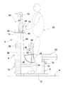
次に、図5〜図8を参照して、本発明に従う立上り・背筋練器具の一実施形態について説明する。図5は、立上り・背筋訓練具の一実施形態を示す側面図であり、図6は、図5におけるVI−VI線による断面図であり、図7は、図5の立上り・背筋訓練具による立上り訓練の状態を示す側面図であり、図8は、図5の立上り・背筋訓練具による背筋訓練の状態を示す側面図である。 Next, with reference to FIG. 5 to FIG. 8, an embodiment of a rising / spinning device according to the present invention will be described. FIG. 5 is a side view showing an embodiment of the standing up / back muscle training tool, FIG. 6 is a cross-sectional view taken along line VI-VI in FIG. 5, and FIG. FIG. 8 is a side view showing a state of standing up training, and FIG. 8 is a side view showing a state of back muscle training using the standing up / back muscle training tool of FIG.
図5及び図6において、図示の立上り訓練具102は、床面104に設置される装置本体106を備え、この装置本体106の前部側(図5において右側、図6において紙面に対して手前側)が訓練部108となり、その後部側(図1において左側、図2において紙面に対して裏側)が負荷部110となっている。訓練部108はフレーム構造となり、負荷部110は後面が開放されたハウジング構造となっている。
5 and 6, the illustrated
この実施形態では、装置本体106は基台フレーム112を備え、この基台フレーム112の後端部に、断面形状コ字状の垂直フレーム本体114が設けられ、この垂直フレーム本体114の前面側が立上り・背筋用の訓練部108となり、その後面側が負荷部110となっている。この基台フレーム112の前端部には座部材116が設けられている。この座部材116は、上述した実施形態と同様のものでよく、基台フレーム112から上方に延びる脚部118と、この脚部118の上端部に設けられた座部120とを備えている。
In this embodiment, the apparatus
この実施形態では、基台フレーム112の前後方向(図5において左右方向、図6において紙面に垂直な方向)の中間部(負荷部110と座部材116との間の部位)に支持フレーム124が設けられ、この支持フレーム124は、基台フレーム112から実質上垂直上方に延びている。支持フレーム124の上端部は一対の接続フレーム126を介して垂直フレーム本体114に接続されている。この支持フレーム124の上端には、幅方向(図5において紙面に垂直な方向、図6において左右方向)に間隔をおいて一対の支持ブラケット128(図5において一方のみ示す)が設けられ、かかる一対の支持ブラケット128に支持軸130が回転自在に支持され、この支持軸130を介して揺動アーム132が揺動自在に支持されている。
In this embodiment, a
揺動アーム132は略L字状のアーム本体134を備え、このアーム本体134の略中央部が支持軸130を介して一対の支持ブラケット128に回転自在に支持され、この支持軸130が揺動アーム132の揺動軸線を構成する。この揺動アーム132の一端部には、後述するように、負荷伝達手段136が連結され、その他端部に、立上り運動及び背筋運動する時に訓練者が把持するための一対の把持手段138(図5において一方のみ示す)が設けられている。これら把持手段138は略棒状の把持部140から構成され、これら把持部140がアーム本体134の両側面から両側に延びている。
The
この実施形態では、上述した実施形態における位置調整機構が座部材116の脚部118に適用されており、この位置調整機構により、脚部118の長さを調整して座部120の高さを変えることができる。また、支持フレーム124の上端部には両側に延びる取付フレーム142(図5において一方のみ示す)が設けられ、これら支持フレーム124及び取付フレーム142の前面に矩形状のクッション144が取り付けられ、図5、図7及び図8から理解されるように、訓練者146の両膝が支持フレーム124に触れる場合、このクッション144に触れるように構成されている。
In this embodiment, the position adjustment mechanism in the above-described embodiment is applied to the
次に、負荷部110及びそれに関連する構成について説明する。この負荷部110は、上述した実施形態の負荷部10と実質上同一の構成であり、断面形状がコ字状である垂直フレーム本体114の内部に、揺動アーム132に負荷を付与するための負荷付与手段148が配設されている。負荷付与手段148は、複数のウエイト150と、これらウエイト150を支持するための支持ロッド152と、これらウエイト150を支持ロッド152に解除自在にロックするための連結ピン(図示せず)から構成されている。各ウエイト150の中央部には上下方向に貫通して貫通孔が設けられ、これら貫通孔内に支持ロッド152が挿入され、また各ウエイト150の底部には、水平方向に延びる連結凹部が設けられているとともに、支持ロッド152には、上下方向に積層されたウエイト150の連結凹部に対応して連結孔(図示せず)が設けられ、連結ピンが特定のウエイト150の連結凹部及び支持ロッド152の対応する連結孔を通して挿通され、このように挿通することによって、この連結ピンを介して連結された特定ウエイト150から上側のウエイト150を支持ロッド152に着脱自在に連結することができる。
Next, the
この負荷付与手段148により付与される負荷は、上述した負荷伝達手段130を介して揺動アーム132に伝達される。図示の負荷伝達手段130は伝達ワイヤ154から構成され、この伝達ワイヤ154の一端部が支持ロッド152の上端部に連結されている。また、装置本体106の垂直フレーム本体114の上端部には矩形状の切欠き156が設けられ、かかる切欠き156に軸158を介して案内プーリ160が回転自在に支持され、伝達ワイヤ154の他端側は、この案内プーリ160に上側から掛けるようにして装置本体106の後側から前側に導かれ、装置本体106の前面に設けられた案内手段162を通してアーム本体134の一端部に連結されている。
The load applied by the
この実施形態における案内手段162は、上下方向に隣接して配設された一対の上案内プーリ164及び下案内プーリ166から構成されている。装置本体106の前面には幅方向に間隔をおいて一対の支持プレート168が設けられ、かかる支持プレート168の上部間に上軸170を介して上案内プーリ164が回転自在に支持され、また支持プレート168の下部間に下軸172を介して下案内プーリ166が回転自在に支持され、案内160から下方に延びる伝達ワイヤ154の他端側は上案内プーリ164及び下案内プーリ166の間を通して前面側に導かれて揺動アーム132の一端部に連結されている。従って、図5に示す状態から揺動アーム132を矢印174で示す時計方向に揺動すると、その一端部が上方に持ち上げられ、伝達ワイヤ154の他端部は上案内プーリ164に巻かれるようになり(図7参照)、また図5に示す状態から揺動アーム132を矢印176で示す反時計方向に揺動すると、その一端部が下方に押し下げられ、伝達ワイヤ154の他端部は下案内プーリ166に巻かれるようになる(図8参照)。
The guide means 162 in this embodiment is composed of a pair of
立上り訓練具102における負荷付与手段148及びそれに関連する構成は、明確に図示していないが、上述した実施形態と同様に構成され、負荷付与手段148としてのウエイト150が一対のガイドポスト(図示せず)に沿って上下方向に移動自在に装着され、このウエイト150に関連して、上述したと同様の反発抵抗付与手段が設けられ、かかる反発抵抗付与手段は直列的に配設された第1及び第2コイルばね部材から構成され、第1ばね部材は、比較的ばね定数が大きいばねから構成されて主として反発抵抗付与作用を発揮し、第2ばね部材86は、比較的ばね定数が小さいばねから構成されて主として衝撃緩衝作用を発揮する。
Although the
上述した立上り・背筋訓練具102を用いて背筋訓練を行うには、次の通りにすればよい。主として図5及び図7を参照して、訓練者146は、垂直フレーム本体114に対向するようにして基台フレーム112上に立ち、その訓練部108に両足を揃えて位置し、図5に示すように、座部材116の座部120に座り、両手で一対の把持手段138を把持する。そして、この状態から図7に示すように、両手で把持手段138を手前側に引っ張って揺動アーム132を矢印174(図5、図7参照)で示す時計方向に揺動させて背筋運動を行う。
In order to perform back muscle training using the above-described rising / back
このよう手前に引っ張って背筋運動をすると、図7に示すように、揺動アーム132の一端部が上方に持ち上げられ、これによって、伝達ワイヤ154の他端部が上方に引っ張られて上案内プーリ164に巻かれ、揺動アーム132の上述した揺動が安定して行われる。伝達ワイヤ154がこのように引っ張られると、この伝達ワイヤ154を介してウエイト150(連結ピンを介して連結された特定ウエイト150から上側のウエイト150)が持ち上げられ、かかるウエイト150が負荷として背筋運動に寄与する広背筋に作用し、このような背筋運動を繰り返すことによって、広背筋の筋力アップを図ることができる。
When the spine exercise is performed by pulling forward in this way, as shown in FIG. 7, one end of the
特に、負荷付与手段148に関連して反発抵抗付与手段(図示せず)が設けられた立上り・背筋訓練具102においては、ウエイト150が上移動から下移動に切り替わる際、即ち背筋訓練中に図7に示すように把持手段138を最も引っ張った際に、上述したと同様に、反発抵抗付与手段の第1コイルばね部材が持ち上げられたウエイト150に作用するので、この反発抵抗力が伝達ワイヤ154を介して揺動アーム132に伝達されて戻り方向に反発力として作用する。従って、この戻り方向の力によってウエイト150の慣性による浮き上がりが防止され、訓練者146はウエイト150の上移動から下移動への切り替えの際にも負荷を感じるようになり、またこの引っ張り状態を維持することによって、背筋に反発抵抗付与手段による負荷(戻し力)が作用し、この負荷作用状態を維持して広背筋を緊張した状態に保つことができ、これによって、広背筋に対してより効果的な筋力アップを図ることができる。
In particular, in the standing up / back
尚、上述した引っ張りを解除すると、ウエイト150の作用によって(当初は反発抵抗付与手段の作用も加わって)、伝達ワイヤ154の他端部が上案内プーリ164に案内されながら下がり、把持手段138を把持した状態にて揺動アーム132が図7において反時計方向に揺動され、図5に示す元の状態に戻る。そして、上述した背筋運動を繰り返し行うことによって背筋訓練を行い、かかる訓練によって広背筋の筋力アップを図ることができる。
When the above-described tension is released, the other end of the
また、この立上り・背筋訓練具102を用いて立上り訓練を行うには、図5に示す状態から図8に示すように、両手で把持手段138を背面側に押し下げて揺動アーム132を矢印176(図5、図8参照)で示す反時計方向に揺動させて立上り運動を行う。
Further, in order to perform standing-up training using the standing-up / back
このように背面側に押し下げて立上り運動をすると、図8に示すように、揺動アーム132の一端部が下方に押し下げられ、これによって、伝達ワイヤ154の他端部が下方に下げられて下案内プーリ166に巻かれ、揺動アーム132の上述した揺動が安定して行われる。伝達ワイヤ154がこのように押し下げられると、上述したと同様に、この伝達ワイヤ154を介してウエイト150(連結ピンを介して連結された特定ウエイト150から上側のウエイト150)が持ち上げられ、かかるウエイト150が負荷として立上り運動に寄与する腸腰筋に作用し、このような立上り運動を繰り返すことによって、腸腰筋の筋力アップを図ることができる。
As shown in FIG. 8, one end of the
特に、このウエイト150が上移動から下移動に切り替わる際、即ち立上り訓練中に図8に示すように把持手段138を最も押し下げた際に、上述したと同様に、反発抵抗付与手段の第1コイルばね部材が持ち上げられたウエイト150に作用するので、この反発抵抗力が伝達ワイヤ154を介して揺動アーム132に伝達されて戻り方向に反発力として作用する。従って、この戻り方向の力によってウエイト150の慣性による浮き上がりが防止され、訓練者146はウエイト150の上移動から下移動への切り替えの際にも負荷を感じるようになり、またこの押し下げた状態を維持することによって、腸腰筋に反発抵抗付与手段による負荷(戻し力)が作用し、この負荷作用状態を維持して腸腰筋を緊張した状態に保つことができ、これによって、腸腰筋に対してより効果的な筋力アップを図ることができる。
In particular, when the
尚、上述した押し下げを解除すると、ウエイト150の作用によって(当初は反発抵抗付与手段の作用も加わって)、伝達ワイヤ154の他端部が下案内プーリ166に案内されながら上がり、把持手段138を把持した状態にて揺動アーム132が図8において時計方向に揺動され、図5に示す元の状態に戻る。そして、上述した立上り運動を繰り返し行うことによって立上り訓練を行い、かかる訓練によって腸腰筋の筋力アップを図ることができる。
When the above-described push-down is released, the other end of the
以上、本発明に従う立上り訓練具、また立上り・背筋訓練具の実施形態について説明したが、本発明はこれら実施形態に限定されるものではなく、本発明の範囲を逸脱することなく種々の変形乃至修正が可能である。 As mentioned above, although the embodiment of the standing-up training tool and the standing-up / back muscle training tool according to the present invention has been described, the present invention is not limited to these embodiments, and various modifications or changes can be made without departing from the scope of the present invention. Correction is possible.
2 立上り訓練具
6,106 装置本体
8,108 訓練部
10,110 負荷部
12,112 基台フレーム
14,114 垂直フレーム本体
16,116 座部材
22,146 訓練者
30,132 揺動アーム
36,144 クッション
42,44,138 把持手段
54,148 負荷付与手段
56,150 ウエイト
62,130 負荷伝達手段
64,154 伝達ワイヤ
80,82 反発抵抗付与手段
84 第1コイルばね
86 第2コイルばね
162 案内手段
164 上案内プーリ
166 下案内プーリ
2 Start-up training tool 6,106 Device main body 8,108 Training unit 10,110 Load unit 12,112 Base frame 14,114 Vertical frame main body 16,116 Seat member 22,146 Trainer 30,132 Swing arm 36,144
Claims (4)
前記一対の把持手段を把持し且つ前記座部材に座った状態にて前記揺動アームの前記クッションを両太股の上側に作用させ、かかる状態にて前記座部材から立ち上がるようにして前記揺動アームを前記揺動軸線を中心として揺動させて立上り運動を行うことを特徴とする立上り訓練具。 A device main body installed on the floor, a swing arm mounted on the device main body so as to be swingable about a swing axis extending in a predetermined direction, a cushion attached to the swing arm, and the swing A load applying means for applying a load to the arm, a load transmitting means for transmitting a load from the load applying means to the swing arm, a pair of gripping means attached to the apparatus main body, and the pair A seat member attached to the apparatus main body facing the gripping means of
The swing arm is configured to act on the upper side of both thighs while holding the pair of gripping means and sitting on the seat member, and to stand up from the seat member in such a state. The rising training tool is characterized in that the rising exercise is performed by swinging the frame around the swing axis.
前記負荷伝達手段は前記案内手段を通して前記揺動アームに連結され、前記座部材に座って前記一対の把持手段を把持し、かかる状態にて前記揺動アームを手前側に引っ張って前記揺動アームを所定方向に揺動させて前記案内手段の上部に案内させるようにして背筋運動を行い、また前記揺動アームを背面側に押して前記揺動アームを所定方向と反対方向に揺動させて前記案内手段の下部に案内させるようにして立上り運動を行うことを特徴とする立上り・背筋訓練具。 An apparatus main body installed on the floor, a swing arm mounted on the apparatus main body so as to be swingable about a swing axis extending in a predetermined direction, and a pair of gripping means provided on the swing arm; A load applying means for applying a load to the swing arm, a load transmitting means for transmitting a load from the load applying means to the swing arm, and a guide provided in association with the load transmitting means Means and a seat member attached to the apparatus body,
The load transmitting means is connected to the swing arm through the guide means, sits on the seat member and grips the pair of grip means, and in this state, pulls the swing arm toward the front side to swing the swing arm. Is swung in a predetermined direction so as to be guided to the upper part of the guide means, and the swing arm is pushed to the back side to swing the swing arm in a direction opposite to the predetermined direction. A standing-up / back-straining exerciser characterized by performing a standing-up exercise so as to be guided to the lower part of the guiding means.
Priority Applications (1)
| Application Number | Priority Date | Filing Date | Title |
|---|---|---|---|
| JP2008049338A JP2009201880A (en) | 2008-02-29 | 2008-02-29 | Standing-up training instrument, and standing-up/back muscle training instrument |
Applications Claiming Priority (1)
| Application Number | Priority Date | Filing Date | Title |
|---|---|---|---|
| JP2008049338A JP2009201880A (en) | 2008-02-29 | 2008-02-29 | Standing-up training instrument, and standing-up/back muscle training instrument |
Publications (1)
| Publication Number | Publication Date |
|---|---|
| JP2009201880A true JP2009201880A (en) | 2009-09-10 |
Family
ID=41144725
Family Applications (1)
| Application Number | Title | Priority Date | Filing Date |
|---|---|---|---|
| JP2008049338A Withdrawn JP2009201880A (en) | 2008-02-29 | 2008-02-29 | Standing-up training instrument, and standing-up/back muscle training instrument |
Country Status (1)
| Country | Link |
|---|---|
| JP (1) | JP2009201880A (en) |
Cited By (3)
| Publication number | Priority date | Publication date | Assignee | Title |
|---|---|---|---|---|
| CN105641859A (en) * | 2014-11-11 | 2016-06-08 | 青岛瑞箭机电工程技术有限公司 | Leg lift exercise rack |
| CN113440794A (en) * | 2021-06-24 | 2021-09-28 | 宋现彬 | Rehabilitation training device for orthopedics department |
| KR20220127997A (en) * | 2021-03-12 | 2022-09-20 | 임교순 | Exercise apparatus for muscle strengthening of perineum and acupuncture point stimulation |
-
2008
- 2008-02-29 JP JP2008049338A patent/JP2009201880A/en not_active Withdrawn
Cited By (5)
| Publication number | Priority date | Publication date | Assignee | Title |
|---|---|---|---|---|
| CN105641859A (en) * | 2014-11-11 | 2016-06-08 | 青岛瑞箭机电工程技术有限公司 | Leg lift exercise rack |
| KR20220127997A (en) * | 2021-03-12 | 2022-09-20 | 임교순 | Exercise apparatus for muscle strengthening of perineum and acupuncture point stimulation |
| KR102566226B1 (en) * | 2021-03-12 | 2023-08-11 | 임교순 | Exercise apparatus for muscle strengthening of perineum and acupuncture point stimulation |
| CN113440794A (en) * | 2021-06-24 | 2021-09-28 | 宋现彬 | Rehabilitation training device for orthopedics department |
| CN113440794B (en) * | 2021-06-24 | 2022-06-24 | 姜涛 | Rehabilitation training device for orthopedics department |
Similar Documents
| Publication | Publication Date | Title |
|---|---|---|
| JP4413192B2 (en) | Training machine | |
| US8951174B2 (en) | Core muscle group training equipment and its method of use | |
| KR101028787B1 (en) | Exercising Apparatus | |
| KR102296498B1 (en) | Lateral Raise Machine | |
| KR200486552Y1 (en) | Barbell Exercise Equipment | |
| JP2012521264A (en) | Isolate curl machine and training method thereof | |
| US7134989B2 (en) | Multifunction exercise machine | |
| JP2009201880A (en) | Standing-up training instrument, and standing-up/back muscle training instrument | |
| EP2907548B1 (en) | Exercise device for strengthening of abdominal muscles | |
| WO2013157158A1 (en) | Bench press/full squat/chin-up apparatus | |
| JP3202923U (en) | Squat training machine | |
| JP2012236009A (en) | Apparatus for bench press, full squat, and pull-up | |
| JP4993945B2 (en) | Training machine | |
| JP2008079722A (en) | Walking training device | |
| JP2007089601A (en) | Training machine | |
| WO2008063048A1 (en) | Training device, training assembly and training method | |
| KR200415322Y1 (en) | The sit-up sporting goods | |
| JP2007089609A (en) | Training machine | |
| KR100668416B1 (en) | The sit-up sporting goods | |
| JP2006239395A (en) | Muscular strength training machine | |
| KR200483889Y1 (en) | Complex Health Machine | |
| JP4004242B2 (en) | Health promotion equipment | |
| JP2015012988A (en) | Exercise equipment | |
| JP3198413U (en) | Health appliances | |
| CN2414782Y (en) | Multifunctional exercising equipment |
Legal Events
| Date | Code | Title | Description |
|---|---|---|---|
| A621 | Written request for application examination |
Free format text: JAPANESE INTERMEDIATE CODE: A621 Effective date: 20110221 |
|
| A072 | Dismissal of procedure |
Free format text: JAPANESE INTERMEDIATE CODE: A073 Effective date: 20120620 |
|
| A300 | Withdrawal of application because of no request for examination |
Free format text: JAPANESE INTERMEDIATE CODE: A300 Effective date: 20120703 |